WO2011027663A1 - 太陽電池用セレン化水素混合ガスの供給方法及び供給装置 - Google Patents
太陽電池用セレン化水素混合ガスの供給方法及び供給装置 Download PDFInfo
- Publication number
- WO2011027663A1 WO2011027663A1 PCT/JP2010/063766 JP2010063766W WO2011027663A1 WO 2011027663 A1 WO2011027663 A1 WO 2011027663A1 JP 2010063766 W JP2010063766 W JP 2010063766W WO 2011027663 A1 WO2011027663 A1 WO 2011027663A1
- Authority
- WO
- WIPO (PCT)
- Prior art keywords
- hydrogen selenide
- gas
- control means
- flow rate
- mixed gas
- Prior art date
- Legal status (The legal status is an assumption and is not a legal conclusion. Google has not performed a legal analysis and makes no representation as to the accuracy of the status listed.)
- Ceased
Links
Images


Classifications
-
- C—CHEMISTRY; METALLURGY
- C01—INORGANIC CHEMISTRY
- C01B—NON-METALLIC ELEMENTS; COMPOUNDS THEREOF; METALLOIDS OR COMPOUNDS THEREOF NOT COVERED BY SUBCLASS C01C
- C01B19/00—Selenium; Tellurium; Compounds thereof
- C01B19/04—Binary compounds including binary selenium-tellurium compounds
-
- Y—GENERAL TAGGING OF NEW TECHNOLOGICAL DEVELOPMENTS; GENERAL TAGGING OF CROSS-SECTIONAL TECHNOLOGIES SPANNING OVER SEVERAL SECTIONS OF THE IPC; TECHNICAL SUBJECTS COVERED BY FORMER USPC CROSS-REFERENCE ART COLLECTIONS [XRACs] AND DIGESTS
- Y02—TECHNOLOGIES OR APPLICATIONS FOR MITIGATION OR ADAPTATION AGAINST CLIMATE CHANGE
- Y02E—REDUCTION OF GREENHOUSE GAS [GHG] EMISSIONS, RELATED TO ENERGY GENERATION, TRANSMISSION OR DISTRIBUTION
- Y02E10/00—Energy generation through renewable energy sources
- Y02E10/50—Photovoltaic [PV] energy
- Y02E10/541—CuInSe2 material PV cells
-
- Y—GENERAL TAGGING OF NEW TECHNOLOGICAL DEVELOPMENTS; GENERAL TAGGING OF CROSS-SECTIONAL TECHNOLOGIES SPANNING OVER SEVERAL SECTIONS OF THE IPC; TECHNICAL SUBJECTS COVERED BY FORMER USPC CROSS-REFERENCE ART COLLECTIONS [XRACs] AND DIGESTS
- Y02—TECHNOLOGIES OR APPLICATIONS FOR MITIGATION OR ADAPTATION AGAINST CLIMATE CHANGE
- Y02E—REDUCTION OF GREENHOUSE GAS [GHG] EMISSIONS, RELATED TO ENERGY GENERATION, TRANSMISSION OR DISTRIBUTION
- Y02E60/00—Enabling technologies; Technologies with a potential or indirect contribution to GHG emissions mitigation
- Y02E60/30—Hydrogen technology
- Y02E60/32—Hydrogen storage
-
- Y—GENERAL TAGGING OF NEW TECHNOLOGICAL DEVELOPMENTS; GENERAL TAGGING OF CROSS-SECTIONAL TECHNOLOGIES SPANNING OVER SEVERAL SECTIONS OF THE IPC; TECHNICAL SUBJECTS COVERED BY FORMER USPC CROSS-REFERENCE ART COLLECTIONS [XRACs] AND DIGESTS
- Y02—TECHNOLOGIES OR APPLICATIONS FOR MITIGATION OR ADAPTATION AGAINST CLIMATE CHANGE
- Y02P—CLIMATE CHANGE MITIGATION TECHNOLOGIES IN THE PRODUCTION OR PROCESSING OF GOODS
- Y02P70/00—Climate change mitigation technologies in the production process for final industrial or consumer products
- Y02P70/50—Manufacturing or production processes characterised by the final manufactured product
Definitions
- the present invention relates to an improvement in a method and apparatus for supplying a hydrogen selenide mixed gas for solar cells.
- the present application claims priority based on Japanese Patent Application No. 2009-205230 filed in Japan on September 4, 2009, the contents of which are incorporated herein by reference.
- Patent Document 1 discloses a chalcopyrite type light absorption layer containing copper, indium, gallium, and selenium and a method for manufacturing the same. Specifically, the chalcopyrite type light absorption layer thin film is formed by depositing copper (Cu), indium (In) and gallium (Ga) on a substrate by sputtering or the like, and then hydrogen selenide (H 2 Se) gas. It is formed by annealing in the atmosphere.
- Cu copper
- In indium
- Ga gallium
- H 2 Se hydrogen selenide
- a hydrogen selenide mixed gas supply apparatus 101 capable of continuously supplying a hydrogen selenide mixed gas is used.
- the supply device 101 is provided with a base gas supply flow path L101 connected to a base gas supply source (not shown) and a source gas supply flow path L102 connected to a source gas supply source (not shown).
- a base gas supply channel L101 and the source gas supply channel L102 are respectively provided with mass flow controllers (MFC) 105 and 112 capable of controlling the flow rate.
- MFC mass flow controllers
- a buffer tank 102 for storing a hydrogen selenide mixed gas adjusted to a predetermined concentration is provided downstream of the base gas supply channel L101 and the source gas supply channel L102.
- the flow rates of the mass flow controllers 105 and 112 provided in the base gas supply flow path L101 and the source gas supply flow path L102 are set to a predetermined value. Set the flow rate ratio.
- 100% hydrogen selenide gas and base gas are mixed with a mixer to adjust to a predetermined concentration, and the resulting selenization for solar cells is performed.
- the hydrogen mixed gas is stored in the buffer tank 102. And this hydrogen selenide mixed gas for solar cells was supplied from the buffer tank 102 to the solar cell manufacturing apparatus.
- the mass flow controller 112 for controlling the flow rate of 100% hydrogen selenide gas provided in the source gas supply flow path L102 detects the thermal diffusion due to the inflow gas by a flow rate sensor and adjusts the flow rate.
- the present invention has been made in view of the above circumstances, and a method for supplying a hydrogen selenide mixed gas for solar cells capable of continuously supplying a hydrogen selenide mixed gas having a stable hydrogen selenide concentration. And it aims at providing a supply apparatus.
- the first aspect of the present invention is adjusted to a predetermined concentration by mixing an inert gas supplied from a base gas supply channel and 100% hydrogen selenide gas supplied from a source gas supply channel.
- a method for supplying a hydrogen selenide mixed gas for solar cells comprising the step of supplying a hydrogen selenide mixed gas, In the supply step, the flow rate control means provided in the source gas supply flow path controls the flow rate of the 100% hydrogen selenide gas to a predetermined flow rate, and pressure control provided on the downstream side of the flow rate control means.
- the flow rate control means is an orifice or a needle valve
- the pressure control means is preferably an automatic pressure control device (APR).
- APR automatic pressure control device
- the said orifice or needle valve is metal.
- the hydrogen selenide mixed gas adjusted to a predetermined concentration is preferably stored in a buffer tank, and a hydrogen selenide mixed gas having a desired concentration is supplied from the buffer tank. .
- the pressure in the channel is reduced at least once, and the flow rate of the 100% hydrogen selenide gas is adjusted after the pressure is finally reduced. Is preferred.
- a hydrogen selenide mixed gas supply device for a solar cell comprising a base gas supply channel and a source gas supply channel, Supplying a hydrogen selenide mixed gas adjusted to a predetermined concentration by mixing an inert gas supplied from the base gas supply channel and a 100% hydrogen selenide gas supplied from the source gas supply channel ,
- the source gas supply flow path has a flow rate control means for controlling the flow rate of the 100% hydrogen selenide gas to a predetermined flow rate, and a pressure control means for controlling the pressure of the 100% hydrogen selenide gas to be constant.
- the pressure control means is a supply device for a hydrogen selenide mixed gas for solar cells provided on the downstream side of the flow rate control means.
- the flow rate control means is an orifice or a needle valve
- the pressure control means is preferably an automatic pressure control device (APR).
- APR automatic pressure control device
- the said orifice or needle valve is metal.
- the second aspect of the present invention preferably further comprises a buffer tank for storing the hydrogen selenide mixed gas adjusted to a predetermined concentration, The buffer tank is preferably provided with a supply port for supplying the hydrogen selenide mixed gas.
- the source gas supply flow path is provided with one or more pressure regulators, It is preferable that the flow rate control means is provided between the pressure regulator on the most downstream side and the pressure control means.
- the method for supplying a hydrogen selenide mixed gas for solar cell controls the flow rate of 100% hydrogen selenide gas to a predetermined flow rate by means of flow rate control means provided in the raw material gas supply flow path.
- the 100% hydrogen selenide gas between the flow rate control means and the pressure control means is supplied while being kept at a predetermined pressure by the pressure control means provided on the downstream side.
- the flow rate control means and the pressure control means by continuous ventilation of 100% hydrogen selenide gas, the flow rate control means and the pressure control means Since the pressure in between can be kept constant, the flow rate of 100% hydrogen selenide gas can be controlled stably.
- the hydrogen selenide mixed gas having a stable concentration can be continuously supplied to the manufacturing process of the solar cell, and thus the solar cell can be mass-produced.
- the hydrogen selenide mixed gas supply device for solar cell of the present invention is provided with a flow rate control means and a pressure control means in the source gas supply flow path, and the pressure control means is provided downstream of the flow rate control means. It has the structure which was made. As a result, the flow rate of the 100% hydrogen selenide gas can be controlled to a predetermined flow rate, and the pressure between the flow rate control means and the pressure control means can be kept constant. It is possible to control the flow rate. Therefore, a hydrogen selenide mixed gas having a stable hydrogen selenide concentration can be continuously supplied.
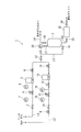
- FIG. 1 It is a schematic diagram which shows the supply apparatus of the hydrogen selenide mixed gas for solar cells which is one Embodiment of this invention. It is a schematic diagram which shows the supply apparatus of the conventional hydrogen selenide mixed gas for solar cells. It is a figure which shows the relationship between the setting value of the hydrogen selenide gas density
- the supply apparatus 1 of this embodiment is an apparatus which supplies the hydrogen selenide mixed gas adjusted to the predetermined density
- the supply device 1 includes a base gas supply channel L1 for supplying a base gas, a source gas supply channel L2 for supplying a source gas, and hydrogen selenide adjusted to a predetermined concentration. And a buffer tank 2 for storing the mixed gas.
- the base gas is not particularly limited as long as it is an inert gas for dilution use.
- the gas include nitrogen (N 2 ) gas, argon (Ar) gas, and the like.
- the base gas supply flow path L1 is provided with an opening / closing valve 3, a pressure regulator 4, a mass flow controller 5, and an automatic valve 6 sequentially from the upstream side to the downstream side.
- Pressure gauges 7 and 8 are provided on the upstream side and the downstream side of the pressure regulator 4, respectively, so that the pressure before and after the pressure regulator 4 can be visually recognized.
- the pressure regulator 4 is provided to reduce the pressure of the base gas supplied from the base gas supply source to a desired pressure.
- the supply apparatus 1 of the present embodiment only one pressure regulator 4 is shown in the base gas supply flow path L1, but the present invention is not limited to this, and two or more pressure regulators 4 are provided. May be.
- the pressure immediately before the mass flow controller 5 can be appropriately selected according to the supply pressure to the solar cell manufacturing apparatus.
- the pressure immediately before the mass flow controller 5 can be in the range of 0.6 to 0.7 MPa.
- the mass flow controller 5 is a flow control device that measures the flow rate of the base gas by measuring the mass flow rate of the base gas, and can perform highly accurate flow rate measurement and control.
- the mass flow sensor mounted on the mass flow controller 5 is not particularly limited, and a general one such as a thermal mass flow sensor or a differential pressure mass flow sensor can be used.
- the source gas supply channel L2 has one end connected to a source gas supply source (not shown) and the other end connected to a mixer (not shown).
- the source gas is hydrogen selenide (H 2 Se) gas having a concentration of 100%. In the present specification, it is simply referred to as 100% hydrogen selenide gas.
- an automatic valve 9 In the source gas supply flow path L2, an automatic valve 9, an on-off valve 10, a pressure regulator 11, a flow rate control means 12, a pressure control means 13, and an automatic valve 14 are sequentially provided from the upstream side to the downstream side. .
- Pressure gauges 15 and 16 are provided on the upstream side and the downstream side of the pressure regulator 11, respectively, so that the pressure before and after the pressure regulator 11 can be visually recognized.
- the pressure regulator 11 is provided to reduce the pressure of 100% hydrogen selenide gas supplied from the source gas supply source to a desired pressure.
- the pressure regulator 11 may not be provided.
- the case where there is no need for pressure reduction is, for example, the case where the source gas flows at a predetermined pressure through the source gas supply flow path L2 without reducing the source gas supply pressure.
- the flow rate control means 12 is provided between the pressure regulator 11 on the most downstream side provided in the source gas supply flow path L2 and the pressure control means 13.
- the flow rate control means 12 is not particularly limited as long as it is a member that can control the flow rate of 100% hydrogen selenide gas, which is a raw material gas, to a predetermined flow rate.
- the member include a needle valve and an orifice.
- the selenium (Se) crystal crystallization produced by the self-decomposition of hydrogen selenide tends to precipitate on a resinous member, it is preferable to use the said needle valve or orifice using a metal.
- FUDDFM-71M-6.35 can be exemplified.
- An example of the orifice is UJR-6.35RE-RG-O-0.5.
- the flow rate on the downstream side of the flow rate control means 12 can be appropriately selected according to the required supply amount of the hydrogen selenide mixed gas. Specifically, for example, the range can be set to 0 to 20 L / min.
- the pressure control means 13 is provided on the downstream side of the flow rate control means 12.
- the pressure control means 13 is not particularly limited as long as it is a member capable of keeping the pressure between the flow rate control means 12 and the pressure control means 13 constant. Examples of the member include an automatic pressure control device (APR).
- APR automatic pressure control device
- the pressure between the flow rate control means 12 and the pressure control means 13 can be appropriately selected according to the supply pressure to the solar cell manufacturing apparatus.
- the pressure managed by the pressure control means 13 can be in the range of 0.5 to 0.6 MPa.
- the mixer (not shown) to which the base gas supply channel L1 and the source gas supply channel L2 are connected and the buffer tank 2 are connected by a channel L3.
- Open / close valves 17 and 18 are provided on the upstream side and the downstream side of the flow path L3, respectively.
- the buffer tank 2 is a storage tank for storing a hydrogen selenide mixed gas adjusted to a predetermined concentration by a mixer.
- capacitance of a buffer tank is not specifically limited, According to the supply amount of the hydrogen selenide mixed gas to a solar cell manufacturing apparatus, it can select suitably.
- the buffer tank 2 is provided with a supply port (not shown). One end of the flow path L4 is connected to the supply port, and the other end of the flow path L4 is connected to the solar cell manufacturing apparatus. . Thereby, the hydrogen selenide mixed gas can be supplied from the buffer tank 2 to the solar cell manufacturing apparatus.
- An opening / closing valve 19 is provided on the supply port side of the flow path L4.
- one end of the flow path L5 is connected to the buffer tank 2, and the other end of the flow path L5 is connected to the pressure gauge 20. With the pressure gauge 20, the pressure in the buffer tank can be confirmed.
- An opening / closing valve 21 is provided in the flow path L5.
- the buffer tank 2 communicates with a flow path L6 branched from the flow path L3.
- the flow path L6 has one end connected to the flow path L3 and the other end connected to an exhaust duct (not shown).
- a gas concentration analyzer 22 is provided in the flow path L6. With this gas concentration analyzer 22, the hydrogen selenide gas concentration in the hydrogen selenide mixed gas in the buffer tank 2 can be measured.
- open / close valves 23 and 24 are provided, respectively.
- the supply method of the present embodiment has a predetermined concentration by mixing the inert gas supplied from the base gas supply flow path L1 and the 100% hydrogen selenide gas supplied from the source gas supply flow path L2.
- a method for supplying a hydrogen selenide mixed gas for solar cells comprising a step of supplying an adjusted hydrogen selenide mixed gas. In the supply step, 100% selenium is produced by a flow rate control means 12 provided in a source gas supply flow path L2.
- the flow rate of the hydrogen selenide gas between the flow rate control means 12 and the pressure control means 13 is controlled by the pressure control means 13 provided downstream of the flow rate control means 12 by controlling the flow rate of the hydrogen fluoride gas.
- the pressure is controlled to a predetermined pressure.
- the opening and closing valves 3, 10, 17, 18, 19, 21, 21, 24 are opened and closed, and the flow path is purged. After the purge is completed, all the open / close valves are opened as shown in FIG.
- an inert gas is supplied from the base gas supply flow path L1, and a 100% hydrogen selenide gas is supplied from the raw material gas supply source L2 to the mixer.
- the inert gas is supplied from the base gas supply source to the base gas supply channel L1.
- the pressure is reduced to a predetermined pressure by the pressure regulator 4 and then introduced into the mass flow controller 5.
- an inert gas having a set flow rate is discharged.
- an inert gas with a predetermined flow rate is supplied to the mixer.
- 100% hydrogen selenide gas is supplied from the source gas supply source to the source gas supply flow path L2.
- the source gas supply flow path L2 after the pressure is reduced to a predetermined pressure by the pressure regulator 11, it is controlled to a predetermined flow rate by an orifice or a needle valve which is the flow rate control means 12.
- the pressure control means 13 controls the pressure between the flow control means 12 and the pressure control means 13 to a predetermined pressure, and the 100% hydrogen selenide gas with a predetermined flow rate when the automatic valve 14 is open. Is fed to the mixer.
- an inert gas and a 100% hydrogen selenide gas supplied at a predetermined flow rate are mixed by a mixer to prepare a hydrogen selenide mixed gas having a predetermined concentration.
- the concentration of the hydrogen selenide mixed gas is not particularly limited, and can be appropriately selected according to the requirements of the solar electric manufacturing apparatus. Specifically, for example, the concentration of hydrogen selenide in the hydrogen selenide mixed gas can be 5 to 20 vol%.
- the hydrogen selenide mixed gas adjusted to a predetermined concentration is supplied to the buffer tank 2 via the flow path L3.
- hydrogen selenide mixed gas is supplied to a solar cell manufacturing apparatus from the flow path L4 connected to the supply port of this buffer tank 2 according to a production condition.
- the pressure in the buffer tank 2 can be measured by the pressure gauge 20.
- the concentration of the hydrogen selenide mixed gas in the buffer tank 2 can be measured by the gas concentration analyzer 22. In this way, a hydrogen selenide mixed gas having a stable hydrogen selenide concentration is continuously supplied to the solar cell manufacturing apparatus.
- the supply of the hydrogen selenide mixed gas to the buffer tank 2 may select a badge method in addition to the continuous method as described above.
- the badge system is a method in which the pressure in the buffer tank 2 is managed within the set upper and lower limits, and the hydrogen selenide mixed gas is supplied so that the pressure in the buffer tank 2 maintains the above management range. is there.
- the automatic valve 6 provided in the base gas supply flow path L1 and the automatic valves 9 and 14 provided in the source gas supply flow path L2 are signaled. Is sent and these automatic valves 2, 9, and 14 are opened.
- these automatic valves 2, 9, 14 are opened, the inert gas and 100% hydrogen selenide gas set to the respective flow rates pass through the mixer and the hydrogen selenide mixed gas adjusted to a predetermined concentration Is supplied into the buffer tank 2.
- a signal is sent to the automatic valves 6 provided in the base gas supply flow path L1 and the automatic valves 9 and 14 provided in the source gas supply flow path L2.
- the supply device 1 of the present embodiment includes the flow rate control means 12 and the pressure control means 13 in the source gas supply flow path L2, and the pressure control means 13 is downstream of the flow rate control means 12. It has the structure provided in. Thereby, the flow rate of the 100% hydrogen selenide gas on the raw material gas side can be controlled to a predetermined flow rate, and the pressure between the flow rate control means 12 and the pressure control means 13 can be kept constant. For this reason, 100% hydrogen selenide gas whose flow rate is controlled to be constant can be stably supplied to the mixer. Therefore, a hydrogen selenide mixed gas having a stable hydrogen selenide concentration can be continuously supplied to the solar cell manufacturing apparatus according to the production status.
- the flow rate of 100% hydrogen selenide gas can be reliably controlled. And precipitation of the crystal
- APR automatic pressure control device
- the supply device 1 of the present embodiment includes the buffer tank 2, the hydrogen selenide mixed gas adjusted to a predetermined concentration can be stored. Thereby, hydrogen selenide mixed gas can be suitably supplied to a solar cell manufacturing apparatus according to the situation of production.
- the flow rate control means 12 provided in the source gas supply flow path L2 controls the flow rate of 100% hydrogen selenide gas to a predetermined flow rate, and the downstream side of the flow rate control means 12 100% hydrogen selenide gas, which is a raw material gas, is supplied by the pressure control means 13 provided at the pressure control means 13 while maintaining the 100% hydrogen selenide gas between the flow rate control means 12 and the pressure control means 13 at a predetermined pressure.
- the flow rate control means 12, and the pressure control means 13 the flow rate control means 12 And the pressure control means 13 can be kept constant.
- the flow rate of 100% hydrogen selenide gas can be controlled stably. That is, even when the hydrogen selenide mixed gas is continuously supplied, the concentration of the target hydrogen selenide mixed gas (set value) and the concentration of the actually prepared hydrogen selenide mixed gas (measured value) ) Will not increase in error.
- the present invention eliminates the influence of precipitation of selenium (Se) crystals generated by continuously venting 100% hydrogen selenide gas, and the hydrogen selenide mixed gas in which the concentration of hydrogen selenide is stable. Can be continuously supplied. Therefore, the hydrogen selenide mixed gas having a stable concentration can be continuously supplied to the production process of the solar cell according to the production amount, and mass production of the solar cell becomes possible.
- Se selenium
- Example 1 The hydrogen selenide mixed gas was continuously supplied to the solar cell manufacturing apparatus using the supply apparatus 1 shown in FIG. A batch system using the buffer tank 2 was used for continuous supply of the hydrogen selenide mixed gas to the solar cell manufacturing apparatus. Moreover, the conditions of Table 1 were used as the conditions of the supply device 1 when supplying the hydrogen selenide mixed gas. After 50 batch processes under the conditions shown in Table 1, the concentration change of the mixed gas was recorded using the gas concentration analyzer 22 connected to the buffer tank 2. The results are shown in Table 2.
- Example 2 The hydrogen selenide mixed gas was continuously supplied to the solar cell manufacturing apparatus using the supply apparatus 101 shown in FIG.
- the batch method using the buffer tank 102 was used for continuous supply of the hydrogen selenide mixed gas to the solar cell manufacturing apparatus, and the conditions shown in Table 1 were used as supply conditions for the hydrogen selenide mixed gas of the supply apparatus 101. .
- the concentration change of the mixed gas was recorded using the gas concentration analyzer 122 connected to the buffer tank 102. The results are shown in Table 2.
- Example 1 to which the present invention is applied exhibits a change in the concentration of the hydrogen selenide mixed gas before and after the continuous supply by about 1 as compared with Example 2 which is the prior art. / 13 was confirmed to be able to be suppressed.
- Supply device (supply device for hydrogen selenide mixed gas for solar cells) 2 ... Buffer tank 3, 10, 14, 17, 18, 19, 21, 23, 24 ... Open / close valve 4, 11 ... Pressure regulator 5 ... Mass flow controller (MFC) 6, 9, 14 ... Automatic valve 7, 8, 15, 16, 20 ... Pressure gauge 12 ... Flow rate control means 13 ... Pressure control means 22 ... Gas concentration analyzer L1 ... Base gas supply flow path L2 ... Raw material gas supply flow path L3 to L6 ... Flow path
Landscapes
- Chemical & Material Sciences (AREA)
- Organic Chemistry (AREA)
- Inorganic Chemistry (AREA)
- Photovoltaic Devices (AREA)
- Chemical Vapour Deposition (AREA)
Abstract
Description
本願は、2009年9月4日に、日本に出願された特願2009-205230号に基づき優先権を主張し、その内容をここに援用する。
本発明の第1の態様は、ベースガス供給流路から供給される不活性ガスと、原料ガス供給流路から供給される100%セレン化水素ガスと、を混合することにより所定の濃度に調整したセレン化水素混合ガスを供給する工程を有する太陽電池用セレン化水素混合ガスの供給方法であって、
前記供給工程において、当該原料ガス供給流路に設けられた流量制御手段により、前記100%セレン化水素ガスの流量を所定の流量に制御し、前記流量制御手段の下流側に設けられた圧力制御手段により、前記流量制御手段と当該圧力制御手段との間の前記100%セレン化水素ガスの圧力を所定の圧力に制御する太陽電池用セレン化水素混合ガスの供給方法である。
前記圧力制御手段が、自動圧力制御装置(APR)であることが好ましい。
また、本発明の第1の態様においては、前記オリフィス又はニードル弁が、金属製であることが好ましい。
また、本発明の第1の態様においては、所定の濃度に調整した前記セレン化水素混合ガスをバッファータンクに貯留し、前記バッファータンクから所望の濃度のセレン化水素混合ガスを供給することが好ましい。
また、本発明の第1の態様においては、前記原料ガス供給流路において、流路内の圧力を1回以上減圧し、最後に減圧した後に前記100%セレン化水素ガスの流量を調整することが好ましい。
ベースガス供給流路から供給される不活性ガスと、原料ガス供給流路から供給される100%セレン化水素ガスと、を混合することにより所定の濃度に調整したセレン化水素混合ガスを供給し、
前記原料ガス供給流路が、前記100%セレン化水素ガスの流量を所定の流量に制御するための流量制御手段と、前記100%セレン化水素ガスの圧力を一定に制御するための圧力制御手段と、を備え、
前記圧力制御手段が、前記流量制御手段の下流側に設けられている太陽電池用セレン化水素混合ガスの供給装置である。
前記圧力制御手段が、自動圧力制御装置(APR)であることが好ましい。
また、本発明の第2の態様においては、前記オリフィス又はニードル弁が、金属製であることが好ましい。
また、本発明の第2の態様は、所定の濃度に調整した前記セレン化水素混合ガスを貯留するバッファータンクをさらに備えることが好ましく、
前記バッファータンクには、前記セレン化水素混合ガスを供給するための供給口が設けられていることが好ましい。
また、本発明の第2の態様は、前記原料ガス供給流路には、1以上の圧力調整器が設けられており、
最下流側の前記圧力調整器と前記圧力制御手段との間に前記流量制御手段が設けられていることが好ましい。
これにより、100%セレン化水素ガスの連続的な通気により、原料ガス供給流路、流量制御手段及び圧力制御手段にセレン(Se)結晶が析出しても、流量制御手段と圧力制御手段との間の圧力を一定に保つことができるため、安定して100%セレン化水素ガスの流量を制御することができる。すなわち、100%セレン化水素ガスの連続的な通気により生じるセレン(Se)結晶の析出による影響を排除して、セレン化水素の濃度が安定したセレン化水素混合ガスを連続的に供給することができる。
このように本発明によれば、太陽電池の製造プロセスに濃度が安定したセレン化水素混合ガスを連続的に供給することができるため、太陽電池の大量生産が可能となる。
なお、以下の説明で用いる図面は、特徴をわかりやすくするために、便宜上特徴となる部分を拡大して示している場合があり、各構成要素の寸法比率などが実際と同じであるとは限らない。
また、本明細書中で用いる単位については、濃度は体積濃度、圧力はゲージ圧力、流量は体積流量を表している。さらに、本明細書中に示す体積は、基準状態(0℃、1atm(大気圧))での体積である。
図1に示すように、本実施形態の供給装置1は、太陽電池の製造装置における生産状況に応じて、所定の濃度に調整したセレン化水素混合ガスを供給する装置である。具体的には、供給装置1は、ベースガスを供給するためのベースガス供給流路L1と、原料ガスを供給するための原料ガス供給流路L2と、所定の濃度に調整されたセレン化水素混合ガスを貯留するためのバッファータンク2と、を備えて概略構成されている。
ベースガスは、希釈用途の不活性ガスであれば特に限定されるものではない。上記ガスとしては、例えば、窒素(N2)ガス、アルゴン(Ar)ガス等が挙げられる。
なお、マスフローコントローラ5の直前の圧力は、太陽電池製造装置への供給圧力に応じて適宜選択することができる。例えば、マスフローコントローラ5の直前の圧力としては、0.6~0.7MPaの範囲とすることができる。
原料ガスは、濃度100%のセレン化水素(H2Se)ガスである。なお、本明細書中では、単に100%セレン化水素ガスと記載する。
また、原料ガス供給にあたり、原料ガスの減圧の必要性がない場合には、圧力調整器11は設けなくてもよい。減圧の必要性がない場合とは、例えば、原料ガス供給圧力を減圧せずとも原料ガスが原料ガス供給流路L2を所定の圧力で流れる場合である。
流量制御手段12の下流側の流量は、必要とされるセレン化水素混合ガスの供給量に応じて適宜選択することができる。具体的には、例えば、0~20L/minの範囲とすることができる。
本実施形態の供給方法は、ベースガス供給流路L1から供給される不活性ガスと、原料ガス供給流路L2から供給される100%セレン化水素ガスと、を混合することにより所定の濃度に調整したセレン化水素混合ガスを供給する工程を有する太陽電池用セレン化水素混合ガスの供給方法であり、供給工程において、原料ガス供給流路L2に設けられた流量制御手段12により、100%セレン化水素ガスの流量を所定の流量に制御し、流量制御手段12の下流側に設けられた圧力制御手段13により、流量制御手段12と圧力制御手段13との間の100%セレン化水素ガスの圧力を所定の圧力に制御するものである。
セレン化水素混合ガスの濃度は、特に限定されるものではなく、太陽電気製造装置の要求に応じて適宜選択することができる。具体的には、例えば、セレン化水素混合ガス中のセレン化水素の濃度を、5~20vol%とすることができる。
このようにして、セレン化水素の濃度が安定したセレン化水素混合ガスを太陽電池製造装置に連続的に供給する。
バッジ方式とは、バッファータンク2内の圧力を設定した上限値及び下限値の範囲で管理し、バッファータンク2内の圧力が上記管理範囲を維持するようにセレン化水素混合ガスを供給する方法である。
また、圧力制御手段13として自動圧力制御装置(APR)を用いているため、流量制御手段12と圧力制御手段13との間の圧力の制御を容易に行うことができる。
(例1)
図1に示す供給装置1を用いて、太陽電池製造装置にセレン化水素混合ガスを連続して供給した。太陽電池製造装置へのセレン化水素混合ガスの連続供給には、バッファータンク2を用いたバッチ方式を用いた。
また、セレン化水素混合ガスの供給時における供給装置1の条件としては、表1の条件を用いた。
表1の条件にて50回のバッチ処理を行った後、バッファータンク2に接続されたガス濃度分析計22を用いて混合ガスの濃度変化を記録した。結果を表2に示す。
図2に示す供給装置101を用いて、太陽電池製造装置にセレン化水素混合ガスを連続して供給した。太陽電池製造装置へのセレン化水素混合ガスの連続供給には、バッファータンク102を用いたバッチ方式を用い、供給装置101のセレン化水素混合ガスの供給条件としては、表1の条件を用いた。
表1の条件にて50回のバッチ処理を行った後、バッファータンク102に接続されたガス濃度分析計122を用いて混合ガスの濃度変化を記録した。結果を表2に示す。


以上より、セレン化水素混合ガスを連続供給した場合に、本発明を適用した例1は、従来技術である例2と比較して、連続供給前後のセレン化水素混合ガスの濃度変化を約1/13程度に抑えることができることを確認した。
2…バッファータンク
3,10,14,17,18,19,21,23,24…開閉バルブ
4,11…圧力調整器
5…マスフローコントローラ(MFC)
6,9,14…自動弁
7,8,15,16,20…圧力計
12…流量制御手段
13…圧力制御手段
22…ガス濃度分析計
L1…ベースガス供給流路
L2…原料ガス供給流路
L3~L6…流路
Claims (10)
- ベースガス供給流路から供給される不活性ガスと、原料ガス供給流路から供給される100%セレン化水素ガスと、を混合することにより所定の濃度に調整したセレン化水素混合ガスを供給する工程を有する太陽電池用セレン化水素混合ガスの供給方法であって、
前記供給工程において、前記原料ガス供給流路に設けられた流量制御手段により、前記100%セレン化水素ガスの流量を所定の流量に制御し、前記流量制御手段の下流側に設けられた圧力制御手段により、前記流量制御手段と当該圧力制御手段との間の前記100%セレン化水素ガスの圧力を所定の圧力に制御する太陽電池用セレン化水素混合ガスの供給方法。 - 前記流量制御手段が、オリフィス又はニードル弁であり、
前記圧力制御手段が、自動圧力制御装置(APR)である請求項1に記載の太陽電池用セレン化水素混合ガスの供給方法。 - 前記オリフィス又はニードル弁が、金属製である請求項2に記載の太陽電池用セレン化水素混合ガスの供給方法。
- 所定の濃度に調整した前記セレン化水素混合ガスをバッファータンクに貯留し、前記バッファータンクから所望の濃度のセレン化水素混合ガスを供給する請求項1に記載の太陽電池用セレン化水素混合ガスの供給方法。
- 前記原料ガス供給流路において、流路内の圧力を1回以上減圧し、最後に減圧した後に前記100%セレン化水素ガスの流量を調整する請求項1に記載の太陽電池用セレン化水素混合ガスの供給方法。
- ベースガス供給流路と、原料ガス供給流路と、を備える太陽電池用セレン化水素混合ガスの供給装置であって、
ベースガス供給流路から供給される不活性ガスと、原料ガス供給流路から供給される100%セレン化水素ガスと、を混合することにより所定の濃度に調整したセレン化水素混合ガスを供給し、
前記原料ガス供給流路が、前記100%セレン化水素ガスの流量を所定の流量に制御するための流量制御手段と、前記100%セレン化水素ガスの圧力を一定に制御するための圧力制御手段と、を備え、
前記圧力制御手段が、前記流量制御手段の下流側に設けられている太陽電池用セレン化水素混合ガスの供給装置。 - 前記流量制御手段が、オリフィス又はニードル弁であり、
前記圧力制御手段が、自動圧力制御装置(APR)である請求項6に記載の太陽電池用セレン化水素混合ガスの供給装置。 - 前記オリフィス又はニードル弁が、金属製である請求項7に記載の太陽電池用セレン化水素混合ガスの供給装置。
- 所定の濃度に調整した前記セレン化水素混合ガスを貯留するバッファータンクをさらに備え、
前記バッファータンクには、前記セレン化水素混合ガスを供給するための供給口が設けられている請求項6に記載の太陽電池用セレン化水素混合ガスの供給装置。 - 前記原料ガス供給流路には、1以上の圧力調整器が設けられており、
最下流側の前記圧力調整器と前記圧力制御手段との間に前記流量制御手段が設けられている請求項6に記載の太陽電池用セレン化水素混合ガスの供給装置。
Priority Applications (3)
| Application Number | Priority Date | Filing Date | Title |
|---|---|---|---|
| KR1020127001216A KR101635122B1 (ko) | 2009-09-04 | 2010-08-13 | 태양 전지용 셀렌화 수소 혼합 가스의 공급 방법 및 공급 장치 |
| CN201080033515.1A CN102471061B (zh) | 2009-09-04 | 2010-08-13 | 太阳能电池用硒化氢混合气体的供给方法以及供给装置 |
| JP2011529864A JP5548208B2 (ja) | 2009-09-04 | 2010-08-13 | 太陽電池用セレン化水素混合ガスの供給方法及び供給装置 |
Applications Claiming Priority (2)
| Application Number | Priority Date | Filing Date | Title |
|---|---|---|---|
| JP2009-205230 | 2009-09-04 | ||
| JP2009205230 | 2009-09-04 |
Publications (1)
| Publication Number | Publication Date |
|---|---|
| WO2011027663A1 true WO2011027663A1 (ja) | 2011-03-10 |
Family
ID=43649205
Family Applications (1)
| Application Number | Title | Priority Date | Filing Date |
|---|---|---|---|
| PCT/JP2010/063766 Ceased WO2011027663A1 (ja) | 2009-09-04 | 2010-08-13 | 太陽電池用セレン化水素混合ガスの供給方法及び供給装置 |
Country Status (5)
| Country | Link |
|---|---|
| JP (1) | JP5548208B2 (ja) |
| KR (1) | KR101635122B1 (ja) |
| CN (1) | CN102471061B (ja) |
| TW (1) | TWI498152B (ja) |
| WO (1) | WO2011027663A1 (ja) |
Cited By (4)
| Publication number | Priority date | Publication date | Assignee | Title |
|---|---|---|---|---|
| US20110044125A1 (en) * | 2006-03-01 | 2011-02-24 | Asahi Organic Chemicals Industry Co., Ltd. | Fluid mixing system |
| JP2014084241A (ja) * | 2012-10-22 | 2014-05-12 | Taiyo Nippon Sanso Corp | 太陽電池用セレン化水素混合ガスの供給方法 |
| JP2015013784A (ja) * | 2013-07-08 | 2015-01-22 | 大陽日酸株式会社 | セレン化水素混合ガス供給装置 |
| JP5663488B2 (ja) * | 2009-10-14 | 2015-02-04 | 大陽日酸株式会社 | 太陽電池用セレン化水素混合ガスの供給方法及び供給装置 |
Families Citing this family (4)
| Publication number | Priority date | Publication date | Assignee | Title |
|---|---|---|---|---|
| KR101661483B1 (ko) * | 2012-10-22 | 2016-09-30 | 다이요 닛산 가부시키가이샤 | 셀렌화수소 혼합 가스의 공급 방법 및 공급 장치 |
| CN106012025A (zh) * | 2016-07-22 | 2016-10-12 | 桂林电子科技大学 | 一种扩散炉气体浓度及扩散方式的自动控制装置 |
| CN110739370B (zh) * | 2019-11-29 | 2021-02-05 | 尚越光电科技股份有限公司 | 一种柔性cigs太阳能电池片硒源加氢增强硒反应活性的系统 |
| CN112066253A (zh) * | 2020-08-06 | 2020-12-11 | 中天合创能源有限责任公司化工分公司 | 一种气相反应器负荷调整气系统 |
Citations (2)
| Publication number | Priority date | Publication date | Assignee | Title |
|---|---|---|---|---|
| JP2007502247A (ja) * | 2003-08-14 | 2007-02-08 | ユニヴァーシティ オブ ヨハネスバーグ | 四元以上のi−iii−vi族アロイ半導体膜 |
| JP2008543563A (ja) * | 2005-06-22 | 2008-12-04 | アドバンスド テクノロジー マテリアルズ,インコーポレイテッド | 一体型のガス混合装置およびプロセス |
Family Cites Families (12)
| Publication number | Priority date | Publication date | Assignee | Title |
|---|---|---|---|---|
| JPS6163599A (ja) * | 1984-09-05 | 1986-04-01 | Matsushita Electric Ind Co Ltd | 気相成長装置 |
| JPS6469874A (en) * | 1987-09-09 | 1989-03-15 | Kyushu Nippon Electric | Mass flow controller |
| US5865206A (en) * | 1997-05-09 | 1999-02-02 | Praxair Technology, Inc. | Process and apparatus for backing-up or supplementing a gas supply system |
| US6363958B1 (en) * | 1999-05-10 | 2002-04-02 | Parker-Hannifin Corporation | Flow control of process gas in semiconductor manufacturing |
| JP3554509B2 (ja) * | 1999-08-10 | 2004-08-18 | 忠弘 大見 | 圧力式流量制御装置における流量異常検知方法 |
| WO2003076059A1 (fr) * | 2002-03-08 | 2003-09-18 | Shuzo Nomura | Melangeur de gaz, reacteur a gaz et dispositif modificateur de surface |
| JP2004302914A (ja) * | 2003-03-31 | 2004-10-28 | Advanced Energy Japan Kk | 一次側圧力のセンサを具えたマスフローコントローラ |
| JP4676771B2 (ja) * | 2004-05-20 | 2011-04-27 | 新光電気工業株式会社 | 化合物半導体太陽電池の製造方法 |
| KR101117749B1 (ko) * | 2006-03-07 | 2012-03-16 | 씨케이디 가부시키 가이샤 | 가스유량 검정유닛 |
| JP4925724B2 (ja) | 2006-05-25 | 2012-05-09 | 本田技研工業株式会社 | 太陽電池およびその製造方法 |
| CN101368265B (zh) * | 2008-06-17 | 2010-09-08 | 华南师范大学 | 一种制备氮化镓薄膜装置中的气路系统 |
| JP5518404B2 (ja) * | 2009-09-04 | 2014-06-11 | 大陽日酸株式会社 | 太陽電池用セレン化水素混合ガスの供給方法及び供給装置 |
-
2010
- 2010-08-13 CN CN201080033515.1A patent/CN102471061B/zh not_active Expired - Fee Related
- 2010-08-13 WO PCT/JP2010/063766 patent/WO2011027663A1/ja not_active Ceased
- 2010-08-13 JP JP2011529864A patent/JP5548208B2/ja not_active Expired - Fee Related
- 2010-08-13 KR KR1020127001216A patent/KR101635122B1/ko not_active Expired - Fee Related
- 2010-08-20 TW TW099127883A patent/TWI498152B/zh not_active IP Right Cessation
Patent Citations (2)
| Publication number | Priority date | Publication date | Assignee | Title |
|---|---|---|---|---|
| JP2007502247A (ja) * | 2003-08-14 | 2007-02-08 | ユニヴァーシティ オブ ヨハネスバーグ | 四元以上のi−iii−vi族アロイ半導体膜 |
| JP2008543563A (ja) * | 2005-06-22 | 2008-12-04 | アドバンスド テクノロジー マテリアルズ,インコーポレイテッド | 一体型のガス混合装置およびプロセス |
Cited By (4)
| Publication number | Priority date | Publication date | Assignee | Title |
|---|---|---|---|---|
| US20110044125A1 (en) * | 2006-03-01 | 2011-02-24 | Asahi Organic Chemicals Industry Co., Ltd. | Fluid mixing system |
| JP5663488B2 (ja) * | 2009-10-14 | 2015-02-04 | 大陽日酸株式会社 | 太陽電池用セレン化水素混合ガスの供給方法及び供給装置 |
| JP2014084241A (ja) * | 2012-10-22 | 2014-05-12 | Taiyo Nippon Sanso Corp | 太陽電池用セレン化水素混合ガスの供給方法 |
| JP2015013784A (ja) * | 2013-07-08 | 2015-01-22 | 大陽日酸株式会社 | セレン化水素混合ガス供給装置 |
Also Published As
| Publication number | Publication date |
|---|---|
| TW201136657A (en) | 2011-11-01 |
| JP5548208B2 (ja) | 2014-07-16 |
| KR20120057605A (ko) | 2012-06-05 |
| TWI498152B (zh) | 2015-09-01 |
| KR101635122B1 (ko) | 2016-06-30 |
| CN102471061B (zh) | 2014-09-24 |
| JPWO2011027663A1 (ja) | 2013-02-04 |
| CN102471061A (zh) | 2012-05-23 |
Similar Documents
| Publication | Publication Date | Title |
|---|---|---|
| JP5548208B2 (ja) | 太陽電池用セレン化水素混合ガスの供給方法及び供給装置 | |
| JP6065329B2 (ja) | セレン化水素混合ガスの供給方法及び供給装置 | |
| JP5518404B2 (ja) | 太陽電池用セレン化水素混合ガスの供給方法及び供給装置 | |
| JP5663488B2 (ja) | 太陽電池用セレン化水素混合ガスの供給方法及び供給装置 | |
| US5496408A (en) | Apparatus for producing compound semiconductor devices | |
| CN103493181B (zh) | 原料的汽化供给装置 | |
| US20150044814A1 (en) | Apparatus and method for forming chalcogenide semiconductor absorber materials with sodium impurities | |
| CN111408289A (zh) | 一种工业化连续高精度混合气体的方法及系统 | |
| JP5873231B2 (ja) | 太陽電池用セレン化水素混合ガスの供給装置及び供給方法 | |
| TWM462748U (zh) | 混生氣體生成設備 | |
| JP5378122B2 (ja) | 太陽電池用セレン化水素混合ガスの供給方法及び供給装置 | |
| CA2010441A1 (fr) | Procede d'elaboration d'une liaison verre-metal et appareil pour sa mise en oeuvre | |
| US20200027730A1 (en) | Film forming method and method of manufacturing semiconductor device | |
| KR20090118428A (ko) | 반도체 제조 공정용 희석가스 공급장치 및 그 방법 | |
| CN221444015U (zh) | 一种镁合金熔炼气体保护装置 | |
| JP6008688B2 (ja) | 太陽電池用セレン化水素混合ガスの供給方法 | |
| CN101514485A (zh) | 一种低氧含量硅晶体的制备方法及设备 | |
| JPH076964A (ja) | 半導体の製造方法 | |
| CN112538615A (zh) | 一种液态源存储系统 | |
| JP2013135133A (ja) | 太陽電池用成膜装置及び太陽電池用成膜方法 |
Legal Events
| Date | Code | Title | Description |
|---|---|---|---|
| WWE | Wipo information: entry into national phase |
Ref document number: 201080033515.1 Country of ref document: CN |
|
| 121 | Ep: the epo has been informed by wipo that ep was designated in this application |
Ref document number: 10813614 Country of ref document: EP Kind code of ref document: A1 |
|
| WWE | Wipo information: entry into national phase |
Ref document number: 2011529864 Country of ref document: JP |
|
| ENP | Entry into the national phase |
Ref document number: 20127001216 Country of ref document: KR Kind code of ref document: A |
|
| NENP | Non-entry into the national phase |
Ref country code: DE |
|
| 122 | Ep: pct application non-entry in european phase |
Ref document number: 10813614 Country of ref document: EP Kind code of ref document: A1 |