WO2011027435A1 - フレーム間ギャップ制御ユニット、トラヒック送信ユニット、伝送装置及びフレーム間ギャップ制御方法 - Google Patents
フレーム間ギャップ制御ユニット、トラヒック送信ユニット、伝送装置及びフレーム間ギャップ制御方法 Download PDFInfo
- Publication number
- WO2011027435A1 WO2011027435A1 PCT/JP2009/065347 JP2009065347W WO2011027435A1 WO 2011027435 A1 WO2011027435 A1 WO 2011027435A1 JP 2009065347 W JP2009065347 W JP 2009065347W WO 2011027435 A1 WO2011027435 A1 WO 2011027435A1
- Authority
- WO
- WIPO (PCT)
- Prior art keywords
- frame
- unit
- traffic
- traffic amount
- inter
- Prior art date
- Legal status (The legal status is an assumption and is not a legal conclusion. Google has not performed a legal analysis and makes no representation as to the accuracy of the status listed.)
- Ceased
Links
Images










Classifications
-
- H—ELECTRICITY
- H04—ELECTRIC COMMUNICATION TECHNIQUE
- H04J—MULTIPLEX COMMUNICATION
- H04J3/00—Time-division multiplex systems
- H04J3/16—Time-division multiplex systems in which the time allocation to individual channels within a transmission cycle is variable, e.g. to accommodate varying complexity of signals, to vary number of channels transmitted
- H04J3/1605—Fixed allocated frame structures
- H04J3/1611—Synchronous digital hierarchy [SDH] or SONET
- H04J3/1617—Synchronous digital hierarchy [SDH] or SONET carrying packets or ATM cells
-
- H—ELECTRICITY
- H04—ELECTRIC COMMUNICATION TECHNIQUE
- H04L—TRANSMISSION OF DIGITAL INFORMATION, e.g. TELEGRAPHIC COMMUNICATION
- H04L47/00—Traffic control in data switching networks
- H04L47/10—Flow control; Congestion control
- H04L47/22—Traffic shaping
-
- H—ELECTRICITY
- H04—ELECTRIC COMMUNICATION TECHNIQUE
- H04L—TRANSMISSION OF DIGITAL INFORMATION, e.g. TELEGRAPHIC COMMUNICATION
- H04L69/00—Network arrangements, protocols or services independent of the application payload and not provided for in the other groups of this subclass
- H04L69/30—Definitions, standards or architectural aspects of layered protocol stacks
- H04L69/32—Architecture of open systems interconnection [OSI] 7-layer type protocol stacks, e.g. the interfaces between the data link level and the physical level
- H04L69/322—Intralayer communication protocols among peer entities or protocol data unit [PDU] definitions
- H04L69/324—Intralayer communication protocols among peer entities or protocol data unit [PDU] definitions in the data link layer [OSI layer 2], e.g. HDLC
Definitions
- the embodiment considered here relates to a technique for controlling an inter-frame gap of an Ethernet (registered trademark) frame.
- Ethernet registered trademark
- WAN Wide Area Network
- the wide area Ethernet network configuration uses an L2 transmission device, an L2 switch, or an L3 switch to transmit an Ethernet frame directly on the WAN.
- the Ethernet frame is transmitted over a synchronous network such as a SONET / SDH network.
- a frame holding means for holding a request frame which is a data transmission request to another processing device, and a response frame including data transmitted from the other processing device in response to the data transmission request among the received frames
- a response measurement unit that calculates a predicted traffic amount that is a traffic amount of a response frame predicted to be received as a response to the request frame based on the measured size, and a response measurement unit
- a bandwidth control device has been proposed that includes a bandwidth control unit that adjusts the timing of transmitting a request frame held by the frame holding unit based on the predicted traffic volume and controls the flow rate of the request frame. According to this bandwidth control device, by calculating the predicted traffic volume, it is possible to indirectly control the flow rate of the response frame by controlling the flow rate of the request frame.
- this bandwidth controller can control larger traffic with smaller buffer consumption. It becomes.
- this bandwidth control device it is possible to handle a significantly larger number of users and traffic volume than the conventional bandwidth control device with a buffer size equivalent to that of the conventional bandwidth control device, and to prevent delay or discard due to congestion. It becomes possible.
- the L2 transmission apparatus, L2 switch, and L3 switch provided in the wide area Ethernet network configuration are equipped with a COS (Class Of Service) function and a QOS (Quality Of Service) function in order to improve communication quality. Therefore, according to the wide area Ethernet network configuration, the burst traffic of the traffic of the Ether frame is smoothed.
- the conventional configuration for transmitting an Ethernet frame through a synchronous network does not have a function for smoothing the burst traffic of the Ethernet frame. For this reason, when burst traffic passes through the synchronous network, packet loss may occur in the network device at the next stage.
- the apparatus and method according to the embodiment are intended to smooth burst traffic in an Ethernet frame transmission apparatus that transmits an Ethernet frame via a synchronous network.
- an inter-frame gap control unit includes an inter-frame gap length determination unit that determines the length of the inter-frame gap according to the traffic amount of the Ether frame that is converted into the synchronous frame and transmitted on the synchronous network, and the inter-frame gap length.
- a gap insertion unit that inserts an interframe gap having a length determined by the determination unit between frames of the Ether frame converted from the synchronization frame.
- the conventional configuration for transmitting an Ethernet frame through a synchronous network does not have a function for smoothing the burst traffic of the Ethernet frame.
- a traffic shaper is realized using the QOS function installed in the L2 transmission device, L2 switch, and L3 switch provided in the wide-area Ethernet network configuration It is possible to do.
- the QOS function involves queuing of Ethernet frames, there is a problem that the circuit configuration of the Ethernet frame transmission apparatus becomes complicated and complicated.
- FIG. 1 is a schematic configuration diagram of a network according to the embodiment.
- Reference numeral 1 indicates a network
- reference numeral 2 indicates a first local area network
- reference numeral 3 indicates a first ether frame transmission apparatus
- reference numeral 4 indicates a synchronous network
- reference numeral 5 indicates a second ether frame
- Reference numeral 6 denotes a transmission apparatus
- reference numeral 6 denotes a second local area network.
- “local area network” is referred to as “LAN”.
- the LAN is referred to as the LAN on the access system side or the lower side network
- the first LAN 2 or the second LAN 6 is given a reference numeral, but each is not limited to a LAN (local network).
- LAN local network
- it may be a network that handles an Ethernet frame, and may be a WAN.
- the network 1 includes a first LAN 2, a second LAN 6, a synchronous network 4 connecting the first LAN 2 and the second LAN 6, a first ether frame transmission device 3, and a second ether frame transmission device 5.
- the first LAN 2 and the second LAN 6 are Ethernet (registered trademark) networks that transmit Ethernet frames.
- the synchronous network 4 is a network that transmits signals on a plurality of time-division multiplexed channels.
- the synchronous network 4 may be a SONET / SDH synchronous network, for example.
- the first Ethernet frame transmission device 3 and the second Ethernet frame transmission device 5 map the Ethernet frame flowing through the Ethernet (registered trademark) network, which is the first LAN 2 or the second LAN 6, to a synchronization frame transmitted on the synchronization network 4, Transmit to the synchronous network 4.
- the first Ethernet frame transmission device 3 and the second Ethernet frame transmission device 5 demap the synchronization frame flowing on the synchronization network 4 to extract the Ethernet frame and transmit it to the first LAN 2 and the second LAN 6, respectively.
- the configuration for transmitting an Ethernet frame on the synchronous network 4 is, for example, POS (PPP over SONET / SDH), EOS (Ether over SONET / SDH), GFP over SONET. May be / SDH.
- the first Ethernet frame transmission device 3 and the second Ethernet frame transmission device 5 are point-to-point (PP) type Ethernet frame transmission devices.
- PP point-to-point
- the PP type Ethernet frame transmission apparatus mainly performs interface processing between the Ethernet (registered trademark) and the synchronous network 4, and does not perform queuing processing or route determination. Therefore, by omitting a network processor that performs relatively sophisticated processing such as queue management and policy management and an L2 switch, the PP type Ethernet frame transmission apparatus can be configured at low cost.
- the first ether frame transmission device 3 and the second ether frame transmission device 5 may have a configuration used when transferring an ether frame from the second ether frame transmission device 5 to the first ether frame transmission device 3. .
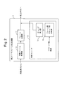
- FIG. 2 is a schematic configuration diagram of a first example of the Ethernet frame transmission apparatus according to the embodiment.
- FIG. 2 shows a configuration used when the second ether frame transmission apparatus 5 receives an ether frame.
- Reference numeral 10 indicates a synchronization frame receiving unit
- reference numeral 11 indicates a frame conversion unit
- reference numeral 12 indicates a control unit
- reference numeral 13 indicates an interframe gap length determination unit
- reference numeral 14 indicates a gap insertion unit. Indicates.
- the synchronization frame reception unit 10 indicates a frame conversion unit 11, and includes a control unit 12.
- the synchronization frame receiving unit 10 receives a synchronization frame transmitted on a time-division multiplexed channel on the synchronization network 4.
- the synchronization frame may be, for example, a SONET / SDH frame.
- the frame conversion unit 11 converts the synchronization frame received by the synchronization frame reception unit 10 into an Ether frame.
- the Ethernet frame converted from the synchronization frame by the frame conversion unit 11 is output to the second LAN 6.
- the control unit 12 adjusts the length of an interframe gap (IFG: Inter-Frame Gap) to be inserted between the frames of the Ether frame converted by the frame conversion unit 11, thereby to output the traffic of the Ether frame to be output to the second LAN 6. Adjust the amount. That is, the control unit 12 shapes the traffic amount of the Ethernet frame output to the second LAN 6 by adjusting the length of the IFG.
- the control unit 12 is an example of an inter-frame gap control unit described in the claims.
- the control unit 12 includes an inter-frame gap length determination unit 13 and a gap insertion unit 14. Part or all of the processing of the interframe gap length determination unit 13 and the gap insertion unit 14 may be executed by a programmable LSI such as an FPGA. Further, part or all of the inter-frame gap length determination unit 13 and the gap insertion unit 14 may be realized by a dedicated hardware circuit. Furthermore, the control unit 12 may include a storage element that stores the processor and its operation program. When the processor executes the operation program, part or all of the inter-frame gap length determination unit 13 and the gap insertion unit process 14 may be executed by the processor.
- the control unit 12 may be provided in the form of a circuit board on which a plurality of functional elements are mounted on an electric circuit board, or a unit including such a circuit board, or provided in the form of an integrated circuit. Also good. The same applies to the following embodiments.
- the interframe gap length determination unit 13 receives traffic amount information indicating the traffic amount of the Ethernet (registered trademark) with respect to the Ethernet frame received from the synchronous network 4 via the synchronous frame.
- the interframe gap length determination unit 13 determines the length of the IFG according to the received traffic volume information.
- the gap insertion unit 14 inserts the IFG having the length determined by the interframe gap length determination unit 13 between the frames of the Ether frame converted by the frame conversion unit 11.
- the present embodiment by adjusting the length of the IFG, it is possible to adjust the traffic amount of the Ethernet frame in the Ethernet frame transmission apparatus that transmits the Ethernet frame from the synchronous network 4 to the second LAN 6.
- This makes it possible to smooth the burst traffic of the Ethernet frame in the Ethernet frame transmission device that transmits the Ethernet frame from the synchronous network 4 to the second LAN 6.
- the packet loss in the second LAN 6 is reduced and the retry process of the upper layer session is reduced, so that the throughput of the entire network is improved.
- the burst traffic in the second LAN 6 it is possible to reduce the hardware, control logic circuit, and control processing used for absorbing the burst traffic arranged in the network device in the second LAN 6. As a result, the equipment cost of the entire network can be reduced.
- FIG. 3 and 4 are schematic configuration diagrams of the second example and the third example of the Ethernet frame transmission apparatus according to the embodiment.
- FIG. 3 shows a configuration used when the second Ethernet frame transmission device 5 receives an Ethernet frame.
- the second Ethernet frame transmission apparatus 5 shown in FIG. 3 has the same configuration as that shown in FIG. 2, and the same reference numerals used in FIG. The same reference numerals are assigned.
- Reference numeral 15 indicates a traffic amount receiving unit.
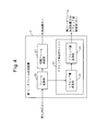
- FIG. 4 shows a configuration used when the first Ethernet frame transmission device 3 transmits an Ethernet frame.
- Reference numeral 20 indicates a frame conversion unit
- reference numeral 21 indicates a synchronization frame transmission unit
- reference numeral 22 indicates a traffic volume transmission unit
- reference numeral 23 indicates a traffic volume measurement unit
- reference numeral 24 indicates a traffic volume transmission. Indicates the part.
- the first Ethernet frame transmission device 3 includes a frame conversion unit 20, a synchronization frame transmission unit 21, and a traffic amount transmission unit 22.
- the frame conversion unit 20 converts the Ethernet frame received from the first LAN 2 into a synchronization frame transmitted on the synchronization network 4.
- the synchronization frame transmission unit 21 transmits the synchronization frame converted by the frame conversion unit 20 to the second Ethernet frame transmission device 5 via the synchronization network 4.
- the traffic amount transmission unit 22 transmits the value of the traffic amount of the ether frame to be transmitted to the second ether frame transmission device 5 via the synchronous network 4 to the traffic amount reception unit 15 of the second ether frame transmission device 5. Therefore, the traffic volume transmission unit 22 includes a traffic volume measurement unit 23 and a traffic volume transmission unit 24.
- the traffic amount transmission unit 22 may include a processor and a storage element that stores an operation program thereof. When the processor executes the operation program, a part or all of the processing of the traffic amount measuring unit 23 and the traffic amount transmitting unit 24 may be executed by the processor.
- the traffic amount transmission unit 22 may be provided in the form of a circuit board on which a plurality of functional elements are mounted on an electric circuit board, or a unit including such a circuit board, and is provided in the form of an integrated circuit. Also good.
- the first Ethernet frame transmission device 3 includes the control unit 12 for use when receiving an Ethernet frame, similarly to the second Ethernet frame transmission device 5, the traffic amount transmission unit 22 and the control unit 12 are used. May be integrated.
- the traffic amount measurement unit 23 measures the value of the traffic amount of the Ethernet frame transmitted to the second Ethernet frame transmission device 5 via the synchronous network 4.
- the measurement method by the traffic amount measurement unit 23 may be the same method as described later with reference to FIGS.
- the traffic amount transmitting unit 24 transmits the measurement value measured by the traffic amount measuring unit 23 to the traffic amount receiving unit 15 of the second Ethernet frame transmission device 5.
- the traffic amount transmitting unit 24 may transmit the measurement value to the traffic amount receiving unit 15 of the second ether frame transmission apparatus 5 via the synchronous network 4.
- the traffic amount transmission unit 24 may transmit the measurement value to the second Ethernet frame transmission device 5 by storing the measurement value in the overhead of the synchronization frame transmitted by the synchronization frame transmission unit 21, for example. Further, the traffic amount transmission unit 24 may transmit the measurement value to the second Ethernet frame transmission device 5 by storing the measurement value in the payload of the synchronization frame transmitted by the synchronization frame transmission unit 21, for example.
- the traffic amount transmission unit 24 may store the measurement value in a control frame used in a predetermined communication procedure performed on the synchronous network 4.
- a communication procedure includes, for example, a general framing procedure (GFP: “Generic” framing “procedure”) performed on the SONET / SDH network.
- GFP general framing procedure
- the measurement value may be transmitted in a state of being stored in a client management frame (CMF: “Client” Management ”Frame) transmitted in a GFP frame.
- the control unit 12 of the second Ethernet frame transmission device 5 includes a traffic amount receiving unit 15. Part or all of the processing of the traffic volume receiving unit 15 may be executed by a programmable LSI such as an FPGA. Further, a part or all of the traffic amount receiving unit 15 may be realized by a dedicated hardware circuit. Further, when the control unit 12 includes a processor and a storage element that stores an operation program thereof, a part or all of the processing of the traffic amount receiving unit 15 may be executed by the processor by the processor executing the operation program.
- the traffic amount receiving unit 15 receives the measurement value transmitted from the traffic amount transmitting unit 24 of the first Ethernet frame transmission device 3.
- the interframe gap length determination unit 13 determines the length of the IFG according to the measurement value received by the traffic amount reception unit 15.
- the second Ethernet frame transmission apparatus 5 measures the traffic volume of the Ethernet frame. It is easier to measure the traffic amount of an Ether frame that is not mapped to the synchronization frame than to measure the traffic amount of the Ether frame that is mapped to the synchronization frame. Therefore, when measuring the traffic amount of the Ethernet frame in the second Ethernet frame transmission device 5, it is preferable to measure in a state where it is not mapped to the synchronization frame.
- the cumulative amount of traffic over a certain measurement period is measured. Therefore, in order to adjust the IFG of the ether frame in this measurement period based on the measurement value measured in the measurement period, a buffer capable of holding the ether frame for a certain period is required. For this reason, in the second Ethernet frame transmission device 5, if an attempt is made to measure the traffic amount of the Ethernet frame in a state where it is not mapped, a buffer that can hold the Ethernet frame for the period required for the measurement after being extracted from the synchronization frame Is required.
- the second ether frame transmission device 5 in order to measure the traffic amount of the ether frame in the first ether frame transmission device 3, it is necessary to provide the second ether frame transmission device 5 with a buffer for holding the ether frame in order to measure the traffic amount. Disappears.
- FIG. 5 is a schematic configuration diagram of a fourth example of the Ethernet frame transmission device according to the embodiment.
- FIG. 5 shows a configuration used when the second Ethernet frame transmission device 5 receives an Ethernet frame.
- the second Ethernet frame transmission device 5 shown in FIG. 5 has the same configuration as the configuration shown in FIG. 2, and the same reference numerals used in FIG. The same reference numerals are assigned.
- Reference numeral 16 denotes a traffic amount measuring unit.
- the control unit 12 includes a traffic amount measurement unit 16. Part or all of the processing of the traffic amount measurement unit 16 may be executed by a programmable LSI such as an FPGA. Further, a part or all of the traffic amount measuring unit 16 may be realized by a dedicated hardware circuit. Further, when the control unit 12 includes a processor and a storage element that stores an operation program thereof, a part or all of the processing of the traffic amount measurement unit 16 may be executed by the processor by the processor executing the operation program.
- the traffic amount measurement unit 16 measures the value of the traffic amount of the Ether frame output from the frame exchange unit 11.
- the measurement method by the traffic amount measurement unit 16 may be the same method as described later with reference to FIGS.
- the interframe gap length determination unit 13 determines the length of the IFG according to the measurement value measured by the traffic amount measurement unit 16.
- the present embodiment it is possible to measure the traffic volume of the Ethernet frame in the second Ethernet frame transmission device 5 on the receiving side that receives the Ethernet frame from the synchronous network 4. For this reason, it is not necessary to measure the traffic amount of the ether frame by the first ether frame transmission device 3 on the transmission side. Further, it is not necessary to transmit the traffic amount measured by the first ether frame transmission device 3.
- FIG. 6 and 7 are schematic configuration diagrams of the fifth and sixth examples of the Ethernet frame transmission device according to the embodiment.
- FIG. 6 shows a configuration used when the first Ethernet frame transmission apparatus 3 transmits an Ethernet frame.
- Reference numeral 30 indicates a LAN interface
- reference numeral 31 indicates a PHY / MAC section
- reference numeral 32 indicates an ingress buffer
- reference numeral 40 indicates an EOS section
- reference numeral 41 indicates a mapping section
- reference numeral 42 Indicates a VCAT generator.
- Reference numeral 50 indicates a WAN interface
- reference numeral 51 indicates a SONET / SDH framer
- reference numeral 60 indicates a control unit
- reference numeral 61 indicates a device control unit
- reference numeral 62 indicates a traffic amount measurement unit
- Reference numeral 63 indicates a traffic amount transmission unit.
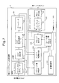
- FIG. 7 shows a configuration used when the second Ethernet frame transmission device 5 receives an Ethernet frame.
- Reference numeral 70 indicates a WAN interface
- reference numeral 71 indicates a SONET / SDH deframer
- reference numeral 80 indicates an EOS section
- reference numeral 81 indicates a VCAT assembly section
- reference numeral 82 indicates a VCAT assembly processing buffer.
- Reference numeral 83 indicates a demapping unit.
- Reference numeral 90 indicates a LAN interface
- reference numeral 91 indicates an egress buffer
- reference numeral 92 indicates a PHY / MAC unit
- Reference numeral 100 represents a control unit
- reference numeral 101 represents an apparatus control unit
- reference numeral 102 represents a traffic amount receiving unit
- reference numeral 103 represents a buffer remaining amount detecting unit
- reference numeral 104 represents an interframe gap length.
- a determination unit is shown
- reference numeral 105 denotes a gap insertion unit.
- a first ether frame transmission device 3 and a second ether frame transmission device 5 shown in FIGS. 6 and 7 are Ethernet frame transmission devices that transmit an ether frame via a SONET / SDH synchronization network as the synchronization network 4.
- the first Ethernet frame transmission device 3 and the second Ethernet frame transmission device 5 may be, for example, PP type Ethernet frame transmission devices.
- the first Ethernet frame transmission device 3 includes a LAN interface 30, an EOS unit 40, a WAN interface 50, and a control unit 60.
- the LAN interface 30 performs interface processing for receiving an Ethernet frame from the first LAN 2 in the first Ethernet frame transmission device 3.
- the LAN interface 30 includes a PHY / MAC unit 31 that performs processing in a physical layer and a MAC layer when receiving an Ethernet frame, and an ingress buffer 32 for temporarily storing an input frame.
- the EOS unit 40 maps the Ethernet frame received by the LAN interface 30 to a SONET / SDH frame.
- the EOS unit 40 is an example of a conversion unit that converts an Ether frame into a synchronization frame, as described in the claims.
- the EOS unit 40 includes a mapping unit 41 and a VCAT generation unit 42.
- the mapping unit 41 maps the Ethernet frame to a frame used in a predetermined procedure or a predetermined protocol executed in the SONET / SDH synchronous network 4.
- the predetermined procedure may be, for example, a generic framing procedure (GFP: “Generic” framing “procedure”).
- the predetermined protocol may be, for example, a point-to-point protocol (PPP: Point to Point Protocol).
- PPP Point to Point Protocol
- a frame used in a predetermined procedure or a predetermined protocol in which an Ethernet frame is mapped by the mapping unit 41 may be referred to as an “intermediate frame”.
- the VCAT generation unit 42 maps the intermediate frame to a virtual path on the SONET / SDH synchronous network 4.
- the WAN interface 50 forms a path and a section for transmitting a SONET / SDH frame via the SONET / SDH synchronous network 4.
- the WAN interface 50 includes a SONET / SDH framer 51 that converts an electrical signal into an optical signal after adding overhead to a frame that has been mapped by the VCAT generation unit 42.
- the control unit 60 receives traffic amount information indicating the value of the traffic amount of the ether frame to be transmitted to the second ether frame transmission device 5 via the SONET / SDH synchronous network 4, and receives the traffic amount of the second ether frame transmission device 5. To the unit 102.
- the control unit 60 includes an apparatus control unit 61, a traffic amount measurement unit 62, and a traffic amount transmission unit 63.
- the control unit 60 is an example of the traffic amount transmission unit described in the claims.
- the control unit 60 may include a storage element that stores a processor and its operation program. When the processor executes the operation program, part or all of the processing of the traffic amount measuring unit 62 and the traffic amount transmitting unit 63 may be executed by the processor.
- the control unit 60 may be provided in the form of a circuit board on which a plurality of functional elements are mounted on an electric circuit board, or a unit including such a circuit board, or may be provided in the form of an integrated circuit. .
- the traffic amount measuring unit 62 measures the value of the traffic amount of the ether frame transmitted to the second ether frame transmission device 5 via the synchronous network 4.
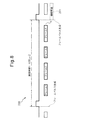
- FIG. 8 is an explanatory diagram of a first example of a traffic amount measurement method.
- the traffic amount measuring unit 62 indicates the number of ether frames to be transmitted to the second ether frame transmission device 5 received by the first ether frame transmission device 3 within a predetermined measurement period, and a value indicating the traffic amount of the ether frame. Measure as In FIG. 8 and FIG. 9 described later, reference numeral 200 indicates a predetermined measurement period.
- the length t of the measurement period is preferably the shortest value among the lengths that can count the number of frames sufficient to be used as an index of traffic volume.
- the value of the length t of the measurement period may be a multiple of a period of 125 ⁇ sec in which the frame pulse is generated in the SONET / SDH synchronous network 4.
- a frame is transmitted with reference to the generation timing of the frame pulse.
- reference numeral 201 indicates traffic amount information indicating a measured value of the traffic amount of the Ethernet frame transmitted in the SONET / SDH frame transmission cycle immediately after the measurement period 200.
- FIG. 9 is an explanatory diagram of a second example of the traffic volume measurement method.
- the traffic amount measuring unit 62 receives the total length of the ether frames to be transmitted to the second ether frame transmission device 5 received by the first ether frame transmission device 3 in the measurement period 200, and the IFG in the measurement period 200. Measure the total length.
- the traffic amount measuring unit 62 measures the ratio between the total length of the ether frames and the total length of the IFG as a value indicating the traffic amount of the ether frames.
- the other points are the same as the measurement method of FIG.
- FIG. 10 is an explanatory diagram of a third example of the method for measuring the traffic volume.
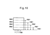
- the traffic amount measuring unit 62 measures the remaining buffer capacity of the ingress buffer 32 as a value indicating the traffic amount of the Ethernet frame. At this time, the traffic amount measuring unit 62 may express the remaining buffer capacity by any one of the predetermined numerical sequences v1, v2,.
- the traffic amount measuring unit 62 determines whether the predetermined numerical value sequence v1, v2,... Is in accordance with the magnitude relationship between the plurality of threshold values set corresponding to the numerical value sequences v1, v2,. One of the numerical values vx indicating the remaining buffer capacity is selected.
- the traffic amount measurement unit 62 determines that the value indicating the remaining buffer capacity is the remaining capacity “4”.
- the traffic amount measuring unit 62 determines that the value indicating the remaining buffer capacity is the remaining capacity “3”.
- the traffic amount measurement unit 62 determines that the value indicating the remaining buffer capacity is the remaining capacity “2”.
- the traffic amount measurement unit 62 determines that the value indicating the remaining buffer capacity is the remaining capacity “1”.
- the traffic amount measuring unit 62 determines that the value indicating the remaining buffer capacity is “0”.
- the remaining buffer capacity is expressed by a predetermined numerical string including a plurality of numerical values “4” to “0” having an order relationship.
- the traffic amount measuring unit 62 may be configured such that the threshold values 1 to 4 and the remaining amount 0 to 4 can be set from the device control unit 61.
- the value indicating the traffic amount of the Ethernet frame may be expressed by a predetermined numerical sequence having an order relationship.
- a plurality of threshold values set corresponding to each value included in the predetermined numerical sequence are compared with the measured value, and the measured value is determined from the predetermined numerical sequence according to the magnitude relationship between the measured value and the plurality of threshold values.
- a value indicating the traffic amount can be expressed by a predetermined numerical sequence.
- the traffic amount information indicating the traffic amount of the Ethernet frame expresses a value indicating the traffic amount by a predetermined numerical sequence having an order relationship.
- traffic amount information that expresses the traffic amount of the Ethernet frame in a format different from the present embodiment may be adopted.
- a value indicating the traffic amount expressed by a predetermined numerical sequence may be referred to as a “traffic amount ID”.
- the traffic amount transmitting unit 63 transmits traffic amount information indicating the traffic amount measured by the traffic amount measuring unit 62 to the traffic amount receiving unit 102 of the second Ethernet frame transmission device 5.
- the traffic amount transmission unit 63 may transmit the traffic amount information to the second Ethernet frame transmission device 5 by mapping the traffic amount information to the path overhead (POH) of the SONET / SDH frame, for example.
- FIG. 11A is an explanatory diagram of a virtual container transmitted by a SONET / SDH frame.
- the virtual container 202 has a POH and a payload portion, and the POH has overhead bytes (OHB) such as “J1”, “B3”, “C2”.
- the traffic volume transmission unit 63 may map the traffic volume information to “C2” bytes that are not used.
- the traffic amount transmission unit 63 may map the traffic amount information to other OHBs other than the “C2” byte.
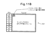
- the traffic volume transmission unit 63 may store the traffic volume information in the payload portion of the virtual container 202 and transmit it to the traffic volume reception unit 102 as shown in FIG. 11B.
- the ingress side equipment uses the specific bytes in the payload part to connect to the egress side.
- LAN line disconnection information may be transmitted to other devices. In such a case, by storing the traffic volume information together with the LAN line disconnection information in the payload portion, the function of transmitting the traffic volume information can be easily realized.
- the traffic amount transmission unit 63 stores the traffic amount information in the CMF transmitted in the GFP frame. Then, it may be transmitted to the traffic amount receiving unit 102.
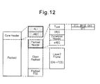
- FIG. 12 is an explanatory diagram of a GFP frame.
- the GFP frame includes a Core Header field and a Payload field, and the Core Header field includes PLI and cHEC.
- PLI indicates the length of the Payload field
- cHEC indicates the result of CRC16 calculation for PLI.
- the Payload field includes a Payload Header field, a Client Payload field, and a Payload FCS field.
- a Layer 2 frame to be transferred is stored in the Client / Payload field, and Payload / FCS indicates a result of performing FCS calculation on the Client / Payload field.
- the Payload header field includes a Type field, a tHEC field, an Extension header field, and an eHEC field.
- the Type field indicates the type of the GFP frame format and the protocol type of the upper layer of the data stored in the Payload field.
- the Type field includes PTI (Payload Type Indicator), PFI (Payload FCS Indicator), EXI (Extension Header Identifier) and UPI (User Payload Identifier).
- the value of the PTI field indicating CMF is “100”.
- the traffic volume transmission unit 63 may store the traffic volume information in the Client Payload field of the CMF and transmit it to the traffic volume reception unit 102.
- the traffic volume transmission unit 63 is configured to be able to set whether or not to transmit traffic volume information from the device control unit 61. Also good.
- the second Ethernet frame transmission device 5 includes a WAN interface 70, an EOS unit 80, a LAN interface 90, and a control unit 100.
- the WAN interface 70 forms a path and a section for transmitting a SONET / SDH frame via the SONET / SDH synchronous network 4.
- the WAN interface 70 includes a SONET / SDH deframer 71.
- the SONET / SDH deframer 71 converts the optical signal transmitted through the SONET / SDH synchronous network 4 into an electrical signal, and then deletes the overhead added to the SONET / SDH frame converted into the electrical signal.
- the EOS unit 80 demaps the SONET / SDH frame output from the WAN interface 70 to the Ethernet frame.
- the EOS unit 80 is an example of a conversion unit that converts a synchronization frame into an Ethernet frame, as described in the claims.
- the EOS unit 80 includes a VCAT assembly unit 81, a VCAT assembly processing buffer 82, and a demapping unit 83.
- the VCAT assembly unit 81 generates the original intermediate frame from the data mapped to the virtual path on the SONET / SDH synchronous network 4.
- the intermediate frame may be a frame used in GFP or PPP.
- the VCAT assembly processing buffer 82 is a buffer for temporarily holding frames during processing by the VCAT assembly unit 81.
- the demapping unit 83 demaps the ether frame from the intermediate frame.
- the LAN interface 90 performs an interface process for transmitting an Ethernet frame from the second Ethernet frame transmission device 5 to the second LAN 6.
- the LAN interface 90 includes an egress buffer 91 for temporarily storing an output frame, and a PHY / MAC unit 92 that performs processing in a physical layer and a MAC layer when transmitting an ether frame.
- the control unit 100 adjusts the length of the IFG inserted between the frames of the ether frame output from the second ether frame transmission device 5 based on the traffic amount information transmitted from the first ether frame transmission device 3.
- the control unit 100 includes a device control unit 101, a traffic amount receiving unit 102, a buffer remaining amount detecting unit 103, an interframe gap length determining unit 104, and a gap inserting unit 105.
- the control unit 100 is an example of an inter-frame gap control unit described in the claims.
- part or all of the processing of the traffic amount receiving unit 102, the remaining buffer amount detecting unit 103, the interframe gap length determining unit 104, and the gap inserting unit 105 may be executed by a programmable LSI such as an FPGA. Further, a part or all of the traffic amount receiving unit 102, the remaining buffer amount detecting unit 103, the interframe gap length determining unit 104, and the gap inserting unit 105 may be realized by a dedicated hardware circuit.
- the control unit 100 may include a storage element that stores a processor and its operation program. When the processor executes the operation program, some or all of the processes of the traffic amount receiving unit 102, the buffer remaining amount detecting unit 103, the interframe gap length determining unit 104, and the gap inserting unit 105 may be executed by the processor. Good.
- the control unit 100 may be provided in the form of a circuit board on which a plurality of functional elements are mounted on an electric circuit board, or a unit including such a circuit board, or may be provided in the form of an integrated circuit. .
- the control unit 60 and the control unit 100 are It may be integral. In this case, the device control unit 61 and the device control unit 101 may be integrated.
- the device control unit 101 determines and changes setting values for determining the operation content of each part of the second ether frame transmission device 5 and the second ether frame transmission device 5.
- the traffic amount receiving unit 102 receives the traffic amount information transmitted from the traffic amount transmitting unit 63 of the first ether frame transmission apparatus 3.
- the buffer remaining amount detection unit 103 detects the buffer remaining amount of the VCAT assembly processing buffer 82 and / or the egress buffer 91.
- the remaining buffer capacity of the VCAT assembly processing buffer 82 and / or the egress buffer 91 is a predetermined value including a plurality of numerical values having an order relationship, as in the method described with reference to FIG. Represented by a numeric string.
- a value indicating the remaining buffer capacity represented by a predetermined numerical string including a plurality of numerical values having an order relationship may be referred to as “buffer remaining capacity ID”.
- the interframe gap length determination unit 104 determines the length of the IFG to be inserted between the frames of the Ethernet frame output from the second Ethernet frame transmission device 5 to the second LAN 6 according to the traffic amount information.
- the interframe gap length determination unit 104 may determine the IFG length by adding not only the traffic amount information but also the remaining buffer capacity of the VCAT assembly processing buffer 82 and / or the egress buffer 91 to the condition. In the following embodiment, the interframe gap length determination unit 104 determines the length of the IFG based on the traffic amount information, the remaining buffer capacity of the VCAT assembly processing buffer 82 and / or the egress buffer 91.
- the gap insertion unit 105 inserts the IFG having the length determined by the inter-frame gap length determination unit 104 between the frames of the ether frame.
- FIG. 13 is an explanatory diagram of the operation of the control unit 100 described in FIG.
- the traffic amount receiving unit 102 receives the traffic amount information extracted by the VCAT assembling unit 81 or the demapping unit 83.
- the traffic amount receiving unit 102 outputs the traffic amount information to the interframe gap length determining unit 104.
- the buffer remaining amount detection unit 103 detects the buffer remaining amount of the VCAT assembly processing buffer 82 and / or the egress buffer 91.
- the buffer remaining amount detection unit 103 outputs the detected traffic remaining amount of the VCAT assembly processing buffer 82 and / or egress buffer 91 to the inter-frame gap length determination unit 104.
- the inter-frame gap length determination unit 104 may have a plurality of profiles that are relationships between the traffic amount information and the buffer remaining amount, and the length of the IFG to be output according to the information. That is, the interframe gap length determination unit 104 can change the length of the IFG to be output by changing the profile even if the conditions determined by the traffic amount information and the buffer remaining amount are the same. By having a plurality of profiles, the interframe gap length determination unit 104 can change the value of the IFG according to the buffer capacity in the second ether frame transmission apparatus 5 and the network configuration.
- the profile to be used is determined by the profile ID specified from the device control unit 101.
- the inter-frame gap length determination unit 104 determines the IFG length according to the traffic amount information, the buffer remaining amount of the VCAT assembly processing buffer 82 and / or the egress buffer 91, and the profile ID. For example, the interframe gap length determination unit 104 may determine the length of the IFG according to an IFG table generated by software or stored in advance.
- FIG. 14 is an explanatory diagram of an example of setting an IFG table.
- the IFG table 210 includes a profile ID field, a traffic amount ID field, a buffer remaining amount ID field, and an IFG insertion number field.
- a profile ID field a profile ID designated by the device control unit 101 is stored.
- the traffic volume ID field stores the traffic volume ID specified by the traffic volume information.
- the buffer remaining amount ID field stores a buffer remaining amount ID indicating the buffer remaining amount of the VCAT assembly processing buffer 82 and / or the egress buffer 91.
- the IFG insertion number field stores the IFG byte length determined according to the combination of IDs specified by the profile ID field, traffic amount ID field, and buffer remaining amount ID field.
- the line indicated by reference number 211 designates the length of the IFG to be inserted as 64 bytes when the profile ID is “1”, the traffic amount ID is “1”, and the remaining buffer ID is “3”.
- the line indicated by reference number 212 designates the length of the IFG to be inserted as 24 bytes when the profile ID is “1”, the traffic volume ID is “3”, and the buffer remaining capacity ID is “3”. To do.
- the order relationship of the traffic volume IDs “1” to “3” indicates that the traffic volume ID “1” indicates a lower traffic volume, the traffic volume ID “3” indicates a higher traffic volume, and the traffic volume. ID “2” indicates that these are intermediate. Further, the order relationship between the buffer remaining amount IDs “1” to “3” indicates that the buffer remaining amount ID “1” has a smaller buffer remaining amount, and the buffer remaining amount ID “3” has a larger buffer remaining amount. The buffer remaining amount ID “2” indicates the intermediate state.
- the inter-frame gap length determination unit 104 assigns an ID indicating the smaller remaining amount of the buffer amount IDs indicating the remaining amounts of the buffers of the VCAT assembly processing buffer 82 and the egress buffer 91 to these remaining buffer amounts. It may be used as a representative of the quantity ID.
- the gap length parameter indicating the length of the IFG determined by the interframe gap length determination unit 104 is input to the gap insertion unit 105.
- the gap insertion unit 105 detects the start (SOF: Start Of Frame) and end (EOF: End Of Frame) of the frame assembled by the VCAT assembly unit 81 and output from the VCAT assembly processing buffer 82.
- the gap insertion unit 105 controls the frame sending operation from the VCAT assembly processing buffer 82 to the demapping unit 83 by outputting and stopping outputting a pulse signal indicating whether or not to output the frame.
- the VCAT assembly processing buffer 82 outputs a frame to the demapping unit 83 when receiving a pulse output indicating whether output is possible or not from the gap insertion unit 105.
- the gap insertion unit 105 inserts the IFG specified by the gap length parameter between the frames of the Ether frame by controlling the interval of the frames output from the VCAT assembly processing buffer 82.
- the second Ethernet frame transmission device 5 is provided with a VCAT assembly processing buffer 82 having a relatively large capacity for the VCAT assembly processing.
- the gap insertion unit 105 may be configured to receive a forced OFF signal from the device control unit 101 according to the case where IFG control according to the present embodiment is not desired.
- the gap insertion unit 105 that has received the forced OFF signal stops the function of adjusting the length of the IFG described above.
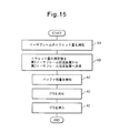
- FIG. 15 is an explanatory diagram of an IFG control method.
- the following operations AA to AE may be steps.
- the traffic amount measuring unit 62 of the first Ethernet frame transmission device 3 measures the value of the traffic amount of the Ethernet frame transmitted to the second Ethernet frame transmission device 5 via the synchronous network 4.
- the traffic volume transmitting unit 63 transmits traffic volume information indicating the value of the measured traffic volume to the traffic volume receiving unit 102 of the second Ethernet frame transmission device 5.
- the remaining buffer capacity detection unit 103 detects the remaining buffer capacity of the VCAT assembly processing buffer 82 and / or the egress buffer 91. Note that the processing of the operation AC is not essential, and the operation AC may be omitted when the IFG is determined without adding the remaining buffer capacity to the condition in the next operation AD. In addition, either of operations AA and AB and operation AC may be executed first.
- the interframe gap length determination unit 104 determines the length of the IFG according to the profile ID specified from the device control unit 101, the traffic amount information received in operation AB, and the remaining buffer capacity detected in operation AC. To decide. Note that the interframe gap length determination unit 104 may determine the length of the IFG according to the traffic amount information or the traffic amount information and the profile ID regardless of the remaining buffer capacity detected in the operation AC.
- the gap insertion unit 105 inserts the IFG having the length determined in operation AD between the Ethernet frames.
- the present embodiment it is possible to adjust the traffic amount of the Ethernet frame in the Ethernet frame transmission apparatus that transmits the Ethernet frame via the SONET / SDH synchronous network.
- burst traffic of the Ethernet frame can be smoothed and traffic can be shaped.
- FIG. 16 is a schematic configuration diagram of a seventh example of the Ethernet frame transmission device according to the embodiment.
- FIG. 16 shows a configuration used when the second Ethernet frame transmission device 5 receives an Ethernet frame.
- the second Ethernet frame transmission device 5 shown in FIG. 16 has the same configuration as the configuration shown in FIG. 7, and the same components as the components shown in FIG. The same reference numerals are assigned.
- part or all of the processing of the traffic amount measurement unit 106 may be executed by a programmable LSI such as an FPGA.
- a part or all of the traffic amount measuring unit 106 may be realized by a dedicated hardware circuit.
- the control unit 100 may include a processor and a storage element that stores an operation program thereof. When the processor executes the operation program, a part or all of the processing of the traffic amount measuring unit 106 may be executed by the processor.
- FIG. 17 is an explanatory diagram of the operation of the control unit 100 described in FIG.
- the traffic amount measuring unit 106 measures the traffic amount of the Ether frame output from the demapping unit 83.
- the method of measuring the traffic amount by the traffic amount measuring unit 106 may be the same as the method described with reference to FIGS.
- the buffer remaining amount detection unit 103 detects the buffer remaining amount of the egress buffer 91.
- the interframe gap length determination unit 104 determines the IFG according to the traffic amount measured by the traffic amount measurement unit 106, the buffer remaining amount detected by the buffer remaining amount detection unit 103, and the profile ID specified by the device control unit 101. Determine the length of the.
- the method for determining the IFG length by the inter-frame gap length determination unit 104 may be the same as the method described above with reference to FIGS.
- the gap insertion unit 105 detects the start (SOF: Start Of Frame) and end (EOF: End Of Frame) of the Ether frame output from the egress buffer 91.
- the gap insertion unit 105 controls the timing of outputting the Ethernet frame from the egress buffer 91 so that the IFG having the length determined by the interframe gap length determination unit 104 is inserted between the frames of the Ethernet frame.
- the present embodiment it is possible to measure the traffic amount of the Ethernet frame in the second Ethernet frame transmission device 5 on the receiving side that receives the Ethernet frame from the SONET / SDH synchronous network 4. For this reason, it is not necessary to measure the traffic amount of the ether frame by the first ether frame transmission device 3 on the transmission side. Further, it is not necessary to transmit the traffic amount measured by the first ether frame transmission device 3.
Landscapes
- Engineering & Computer Science (AREA)
- Computer Networks & Wireless Communication (AREA)
- Signal Processing (AREA)
- Computer Security & Cryptography (AREA)
- Data Exchanges In Wide-Area Networks (AREA)
- Small-Scale Networks (AREA)
- Synchronisation In Digital Transmission Systems (AREA)
Abstract
フレーム間ギャップ制御ユニット12は、同期フレームに変換されて同期網4上を伝送されるイーサフレームのトラヒック量に応じてフレーム間ギャップの長さを決定するフレーム間ギャップ長決定部13と、フレーム間ギャップ長決定部13により決定された長さのフレーム間ギャップを、同期フレームから変換されるイーサフレームのフレーム間に挿入するギャップ挿入部14と、を備える。
Description
ここで検討される実施形態は、イーサネット(登録商標)フレームのフレーム間ギャップを制御する技術に関する。
イーサネット(登録商標)フレームを伝送するイーサネット(登録商標)フレーム伝送装置を広域通信網(WAN: Wide Area Network)回線に接続する構成例としては、広域イーサネット(登録商標)網構成と、同期網で伝送する構成とが知られている。なお、簡単のため、以下の説明において、イーサネット(登録商標)を「イーサ」と略して記載することがある。
広域イーサ網構成は、L2伝送装置、L2スイッチやL3スイッチを用いて、イーサフレームを直接WAN上で伝送する。同期網で伝送する構成の場合には、イーサフレームはSONET/SDH網などの同期網上で伝送される。
なお、受信フレームのうち、他の処理装置に対するデータ送信要求であるリクエストフレームを保持するフレーム保持手段と、受信フレームのうちデータ送信要求を受けて他の処理装置から送信されたデータを含むレスポンスフレームのサイズを計測し、計測されたサイズに基づいて、リクエストフレームに対する応答として受信されると予測されるレスポンスフレームによるトラヒックの量である予測トラヒック量を算出するレスポンス計測手段と、レスポンス計測手段によって算出された予測トラヒック量に基づいて、フレーム保持手段によって保持されるリクエストフレームを送信するタイミングを調整し、リクエストフレームの流量制御を行う帯域制御手段と、を備える帯域制御装置が提案されている。この帯域制御装置によれば、予測トラヒック量を算出することで、リクエストフレームの流量制御によって間接的にレスポンスフレームの流量を制御することを可能としている。リクエストフレームに比べ、リクエストされたデータを含むレスポンスフレームの方がサイズが大きいことが通常であるため、この帯域制御装置によれば、より小さなバッファ消費量で、より大きなトラヒックを制御することが可能となる。またこの帯域制御装置によれば、従来の帯域制御装置と同等のバッファサイズで、従来の帯域制御装置よりも格段に多くのユーザ数およびトラヒック量を扱い、輻輳による遅延又は廃棄を防止することが可能となる。
広域イーサ網構成に設けられるL2伝送装置、L2スイッチやL3スイッチには、通信品質を向上させるために、COS(Class Of Service)機能やQOS(Quality Of Service)機能が搭載される。このため広域イーサ網構成によれば、イーサフレームのトラヒックのバーストトラヒックが平滑化される。一方で、イーサフレームを同期網で伝送する従来の構成には、イーサフレームのバーストトラヒックを平滑化する機能が用意されていない。このため、バーストトラヒックが同期網を通過すると、次段のネットワーク機器においてパケットロスが生じる恐れがある。
実施形態に係る装置及び方法は、同期網を経由してイーサフレームを伝送するイーサフレーム伝送装置において、バーストトラヒックを平滑化することを目的とする。
実施例の一形態によればフレーム間ギャップ制御ユニットが与えられる。本フレーム間ギャップ制御ユニットは、同期フレームに変換されて同期網上を伝送されるイーサフレームのトラヒック量に応じてフレーム間ギャップの長さを決定するフレーム間ギャップ長決定部と、フレーム間ギャップ長決定部により決定された長さのフレーム間ギャップを、同期フレームから変換されるイーサフレームのフレーム間に挿入するギャップ挿入部と、を備える。
上記実施例によれば、同期網を経由してイーサフレームを伝送するイーサフレーム伝送装置において、イーサフレームのバーストトラヒックを平滑化することが可能となる。
本発明の目的及び利点は、特に特許請求の範囲に示した要素及びその組合せを用いて具現化され達成される。前述の一般的な記述及び以下の詳細な記述の両方は、単なる例示及び説明であり、特許請求の範囲のように本発明を限定するものでないと解するべきである。
上述のように、イーサフレームを同期網で伝送する従来の構成には、イーサフレームのバーストトラヒックを平滑化する機能が用意されていない。イーサフレームを同期網で伝送する構成においてバーストトラヒックを平滑化する手法の一例として、広域イーサ網構成に設けられるL2伝送装置やL2スイッチ、L3スイッチに搭載されたQOS機能を用いてトラヒックシェーパを実現することが考えられる。しかし、QOS機能はイーサフレームのキューイングを伴うため、イーサフレーム伝送装置の回路構成が処理や複雑になるという問題がある。
以下、添付される図面を参照して、好ましい実施例について説明する。図1は、実施例に係るネットワークの概略構成図である。参照符号1はネットワークを示し、参照符号2は第1ローカルエリアネットワークを示し、参照符号3は第1イーサフレーム伝送装置を示し、参照符号4は同期網を示し、参照符号5は第2イーサフレーム伝送装置を示し、参照符号6は第2ローカルエリアネットワークを示す。なお、以下の説明及び図面において「ローカルエリアネットワーク」を「LAN」と記載する。ここで、説明の便宜上、WANのアクセス系側または下位側ネットワークの意味合いでLANと称し第1LAN2あるいは第2LAN6と参照符号を付与したが、各々LAN(ローカルネットワーク)に限定するものではない。例えば、イーサフレームを取り扱うネットワークであればよく、WANであってもよい。
ネットワーク1は、第1LAN2と、第2LAN6と、第1LAN2及び第2LAN6の間を接続する同期網4と、第1イーサフレーム伝送装置3と、第2イーサフレーム伝送装置5を含む。
第1LAN2及び第2LAN6は、イーサフレームを伝送するイーサネット(登録商標)網である。一方で、同期網4は、時分割多重された複数のチャネル上で信号を伝送するネットワークである。同期網4は、例えばSONET/SDH同期網であってよい。
第1イーサフレーム伝送装置3及び第2イーサフレーム伝送装置5は、第1LAN2や第2LAN6であるイーサネット(登録商標)網を流れるイーサフレームを、同期網4上で伝送される同期フレームへマッピングし、同期網4へ送信する。また第1イーサフレーム伝送装置3及び第2イーサフレーム伝送装置5は、同期網4上を流れる同期フレームをデマッピングしてイーサフレームを取り出し、それぞれ第1LAN2及び第2LAN6に送信する。
なお同期網4がSONET/SDH同期網であるとき、イーサフレームを同期網4上で伝送させる構成は、例えばPOS(PPP over SONET/SDH)や、EOS(Ether over SONET/SDH)、GFP over SONET/SDHであってよい。また、同期網4がSONET/SDH同期網であるとき、第1イーサフレーム伝送装置3及び第2イーサフレーム伝送装置5は、ポイントトゥポイント(P-P: Point to Point)型イーサフレーム伝送装置であってよい。P-P型イーサフレーム伝送装置は、イーサネット(登録商標)と同期網4との間のインタフェース処理を主に行うものであり、キューイング処理や方路決定を行わない。したがって、キュー管理及びポリシー管理等の比較的高度な処理を行うネットワークプロセッサや、L2スイッチを省くことにより、P-P型イーサフレーム伝送装置は安価に構成できる。
以下の説明では、第1イーサフレーム伝送装置3から第2イーサフレーム伝送装置5へイーサフレームを伝送する場合について説明する。このため以下の説明では、第2イーサフレーム伝送装置5から第1イーサフレーム伝送装置3へイーサフレームを転送する場合に使用される構成及び処理については説明を省略する。第1イーサフレーム伝送装置3及び第2イーサフレーム伝送装置5は、第2イーサフレーム伝送装置5から第1イーサフレーム伝送装置3へイーサフレームを転送する場合に使用される構成を備えていてもよい。
図2は、実施例に係るイーサフレーム伝送装置の第1例の概略構成図である。図2は、第2イーサフレーム伝送装置5においてイーサフレームを受信する場合に使用される構成を示す。参照符号10は同期フレーム受信部を示し、参照符号11はフレーム変換部を示し、参照符号12は制御ユニットを示し、参照符号13はフレーム間ギャップ長決定部を示し、参照符号14はギャップ挿入部を示す。
第2イーサフレーム伝送装置5は、同期フレーム受信部10は、フレーム変換部11を示し、制御ユニット12を備える。同期フレーム受信部10は、同期網4上において時分割多重化されたチャネル上で伝送される同期フレームを受信する。同期網4がSONET/SDH同期網であるとき、同期フレームは例えばSONET/SDHフレームであってよい。
フレーム変換部11は、同期フレーム受信部10が受信した同期フレームをイーサフレームへ変換する。フレーム変換部11によって同期フレームから変換されたイーサフレームは、第2LAN6へ出力される。制御ユニット12は、フレーム変換部11により変換されるイーサフレームのフレーム間に挿入するフレーム間ギャップ(IFG: Inter-Frame Gap)の長さを調整することにより、第2LAN6へ出力するイーサフレームのトラヒック量を調整する。すなわち、制御ユニット12は、IFGの長さを調整することによって、第2LAN6へ出力するイーサフレームのトラヒック量をシェーピングする。なお、制御ユニット12は、特許請求の範囲に記載されるフレーム間ギャップ制御ユニットの一例として挙げられる。
このため制御ユニット12は、フレーム間ギャップ長決定部13と、ギャップ挿入部14を備える。なお、フレーム間ギャップ長決定部13及びギャップ挿入部14の処理の一部又は全部は、FPGAなどのプログラム可能なLSIによって実行されてよい。また、フレーム間ギャップ長決定部13及びギャップ挿入部14の一部又は全部は、専用のハードウエア回路によって実現されてもよい。さらに制御ユニット12は、プロセッサとその動作プログラムを記憶する記憶素子を備えてもよい。プロセッサが動作プログラムを実行することにより、フレーム間ギャップ長決定部13及びギャップ挿入部の処理14の一部又は全部が、プロセッサにより実行されてよい。
また、制御ユニット12は、複数の機能要素を電気回路用基板の上に搭載する回路ボード、またはこのような回路ボードを含むユニットの形態で与えられてもよく、集積回路の形態で与えられてもよい。以下の実施例でも同様である。
フレーム間ギャップ長決定部13は、同期フレームを介して同期網4から受信されるイーサフレームに関して、これらイーサネット(登録商標)のトラヒック量を表すトラヒック量情報を受信する。フレーム間ギャップ長決定部13は、受信したトラヒック量情報に応じてIFGの長さを決定する。ギャップ挿入部14は、フレーム間ギャップ長決定部13により決定された長さのIFGを、フレーム変換部11により変換されるイーサフレームのフレーム間に挿入する。
本実施例によれば、IFGの長さを調整することによって、イーサフレームを同期網4から第2LAN6へ伝送するイーサフレーム伝送装置において、イーサフレームのトラヒック量を調整することが可能となる。これによって、イーサフレームを同期網4から第2LAN6へ伝送するイーサフレーム伝送装置において、イーサフレームのバーストトラヒックを平滑化することが可能となる。この結果、第2LAN6におけるパケットロスが低減して、上位レイヤのセッションのリトライ処理が減少するため、ネットワーク全体のスループットが向上する。
また、第2LAN6におけるバーストトラヒックを低減することにより、第2LAN6内のネットワーク機器に配置する、バーストトラヒックを吸収するために用いられるハードウエアや制御用論理回路、制御処理を削減できる。その結果、ネットワーク全体の設備費用を削減することができる。
図3及び図4は、実施例に係るイーサフレーム伝送装置の第2例及び第3例の概略構成図である。図3は、第2イーサフレーム伝送装置5においてイーサフレームを受信する場合に使用される構成を示す。図3に示される第2イーサフレーム伝送装置5は、図2に示す構成と同様の構成を有しており、図2に示す構成要素と同様の構成要素には図2で使用した参照符号と同じ参照符号を付する。参照符号15は、トラヒック量受信部を示す。
図4は、第1イーサフレーム伝送装置3においてイーサフレームを送信する場合に使用される構成を示す。参照符号20はフレーム変換部を示し、参照符号21は同期フレーム送信部を示し、参照符号22はトラヒック量送信ユニットを示し、参照符号23はトラヒック量測定部を示し、参照符号24はトラヒック量送信部を示す。
第1イーサフレーム伝送装置3は、フレーム変換部20と、同期フレーム送信部21と、トラヒック量送信ユニット22を備える。フレーム変換部20は、第1LAN2から受信されるイーサフレームを、同期網4上で伝送される同期フレームへ変換する。同期フレーム送信部21は、フレーム変換部20によって変換された同期フレームを、第2イーサフレーム伝送装置5へ同期網4を経由して送信する。
トラヒック量送信ユニット22は、同期網4を経由して第2イーサフレーム伝送装置5へ送信するイーサフレームのトラヒック量の値を、第2イーサフレーム伝送装置5のトラヒック量受信部15へ送信する。このためトラヒック量送信ユニット22は、トラヒック量測定部23と、トラヒック量送信部24を備える。
なお、トラヒック量測定部23及びトラヒック量送信部24の処理の一部又は全部は、FPGAなどのプログラム可能なLSIによって実行されてよい。また、トラヒック量測定部23及びトラヒック量送信部24の一部又は全部は、専用のハードウエア回路によって実現されてもよい。トラヒック量送信ユニット22は、プロセッサとその動作プログラムを記憶する記憶素子を備えてもよい。プロセッサが動作プログラムを実行することにより、トラヒック量測定部23及びトラヒック量送信部24の処理の一部又は全部が、プロセッサにより実行されてもよい。
トラヒック量送信ユニット22は、複数の機能要素を電気回路用基板の上に搭載する回路ボード、またはこのような回路ボードを含むユニットの形態で与えられてもよく、集積回路の形態で与えられてもよい。なお、第1イーサフレーム伝送装置3が、第2イーサフレーム伝送装置5と同様にイーサフレームを受信する際に使用するために制御ユニット12を有する場合には、トラヒック量送信ユニット22と制御ユニット12とは一体であってもよい。
トラヒック量測定部23は、同期網4を経由して第2イーサフレーム伝送装置5へ送信するイーサフレームのトラヒック量の値を測定する。トラヒック量測定部23による測定方法は、図8~図10を参照して後述する方法と同様の方法であってよい。
トラヒック量送信部24は、トラヒック量測定部23によって測定された測定値を、第2イーサフレーム伝送装置5のトラヒック量受信部15へ送信する。トラヒック量送信部24は、同期網4を経由して、第2イーサフレーム伝送装置5のトラヒック量受信部15へ測定値を送信してよい。トラヒック量送信部24は、例えば同期フレーム送信部21により送信される同期フレームのオーバヘッドに測定値を格納することにより、測定値を第2イーサフレーム伝送装置5へ送信してよい。また、トラヒック量送信部24は、例えば同期フレーム送信部21により送信される同期フレームのペイロードに測定値を格納することにより、第2イーサフレーム伝送装置5へ測定値を送信してよい。
また、トラヒック量送信部24は、同期網4上で実施される所定の通信手順にて使用される制御フレームに測定値を格納してよい。このような通信手順には、例えば、SONET/SDH網上で実施される汎用フレーミングプロシージャ(GFP: Generic framing procedure)がある。例えば、測定値は、GFPフレームにて送信されるクライアント管理フレーム(CMF: Client Management Frame)に格納された状態で送信されてよい。
図3を参照する。第2イーサフレーム伝送装置5の制御ユニット12は、トラヒック量受信部15を備える。トラヒック量受信部15の処理の一部又は全部は、FPGAなどのプログラム可能なLSIによって実行されてよい。また、トラヒック量受信部15の一部又は全部は、専用のハードウエア回路によって実現されてもよい。さらに制御ユニット12がプロセッサとその動作プログラムを記憶する記憶素子を備えるとき、プロセッサが動作プログラムを実行することにより、トラヒック量受信部15の処理の一部又は全部がプロセッサにより実行されてよい。
トラヒック量受信部15は、第1イーサフレーム伝送装置3のトラヒック量送信部24から送信された測定値を受信する。フレーム間ギャップ長決定部13は、トラヒック量受信部15が受信した測定値に応じて、IFGの長さを決定する。
本実施例によれば、イーサフレームを同期網4へ送信する送信側の第1イーサフレーム伝送装置3において、イーサフレームのトラヒック量を測定することが可能となる。このため、受信側の第2イーサフレーム伝送装置5においてイーサフレームのトラヒック量を測定せずにすむ。
受信側の第2イーサフレーム伝送装置5におけるトラヒック量の測定を不要にすることの利点を以下に説明する。いま、第2イーサフレーム伝送装置5においてイーサフレームのトラヒック量を測定することを考える。同期フレームにマッピングされた状態のイーサフレームのトラヒック量を測定するよりも、同期フレームにマッピングされていない状態のイーサフレームのトラヒック量を測定する方が容易である。したがって、第2イーサフレーム伝送装置5においてイーサフレームのトラヒック量を測定する場合には、同期フレームにマッピングされていない状態で測定する方が好ましい。
トラヒック量の測定では、ある測定期間に亘るトラヒック量の累積量が測定される。したがって、測定期間において測定された測定値に基づいてこの測定期間のイーサフレームのIFGを調整するために、イーサフレームをある程度の期間保持できるバッファが必要になる。このため、第2イーサフレーム伝送装置5において、マッピングされていない状態でイーサフレームのトラヒック量を測定しようとすると、同期フレームから取り出した後で、測定に必要な期間のあいだイーサフレームを保持できるバッファが必要になる。
本実施例によれば、第1イーサフレーム伝送装置3においてイーサフレームのトラヒック量を測定するため、トラヒック量の測定のためにイーサフレームを保持するバッファを、第2イーサフレーム伝送装置5に設ける必要がなくなる。
図5は、実施例に係るイーサフレーム伝送装置の第4例の概略構成図である。図5は、第2イーサフレーム伝送装置5においてイーサフレームを受信する場合に使用される構成を示す。図5に示される第2イーサフレーム伝送装置5は、図2に示す構成と同様の構成を有しており、図2に示す構成要素と同様の構成要素には図2で使用した参照符号と同じ参照符号を付する。参照符号16は、トラヒック量測定部を示す。
制御ユニット12は、トラヒック量測定部16を備える。トラヒック量測定部16の処理の一部又は全部は、FPGAなどのプログラム可能なLSIによって実行されてよい。また、トラヒック量測定部16の一部又は全部は、専用のハードウエア回路によって実現されてもよい。さらに制御ユニット12がプロセッサとその動作プログラムを記憶する記憶素子を備えるとき、プロセッサが動作プログラムを実行することにより、トラヒック量測定部16の処理の一部又は全部がプロセッサにより実行されてよい。
トラヒック量測定部16は、フレーム交換部11から出力されるイーサフレームのトラヒック量の値を測定する。トラヒック量測定部16による測定方法は、図8及び図9を参照して後述する方法と同様の方法であってよい。フレーム間ギャップ長決定部13は、トラヒック量測定部16により測定された測定値に応じて、IFGの長さを決定する。
本実施例によれば、同期網4からイーサフレームを受信する受信側の第2イーサフレーム伝送装置5において、イーサフレームのトラヒック量を測定することが可能となる。このため、送信側の第1イーサフレーム伝送装置3でイーサフレームのトラヒック量を測定せずにすむ。また、第1イーサフレーム伝送装置3で測定されたトラヒック量を伝送しなくてすむ。
図6及び図7は、実施例に係るイーサフレーム伝送装置の第5例及び第6例の概略構成図である。図6は、第1イーサフレーム伝送装置3においてイーサフレームを送信する場合に使用される構成を示す。参照符号30はLANインタフェースを示し、参照符号31はPHY/MAC部を示し、参照符号32はイングレスバッファを示し、参照符号40はEOS部を示し、参照符号41はマッピング部を示し、参照符号42はVCAT生成部を示す。
参照符号50はWANインタフェースを示し、参照符号51はSONET/SDHフレーマを示し、参照符号60は制御ユニットを示し、参照符号61は装置制御部を示し、参照符号62はトラヒック量測定部を示し、参照符号63はトラヒック量送信部を示す。
図7は、第2イーサフレーム伝送装置5においてイーサフレームを受信する場合に使用される構成を示す。参照符号70はWANインタフェースを示し、参照符号71はSONET/SDHデフレーマを示し、参照符号80はEOS部を示し、参照符号81はVCAT組立部を示し、参照符号82はVCAT組立処理用バッファを示し、参照符号83はデマッピング部を示す。
参照符号90はLANインタフェースを示し、参照符号91はイーグレスバッファを示し、参照符号92はPHY/MAC部を示す。参照符号100は制御ユニットを示し、参照符号101は装置制御部を示し、参照符号102はトラヒック量受信部を示し、参照符号103はバッファ残量検知部を示し、参照符号104はフレーム間ギャップ長決定部を示し、参照符号105はギャップ挿入部を示す。
図6及び図7にそれぞれ示す第1イーサフレーム伝送装置3及び第2イーサフレーム伝送装置5は、同期網4としてのSONET/SDH同期網を経由してイーサフレームを伝送するイーサフレーム伝送装置である。第1イーサフレーム伝送装置3及び第2イーサフレーム伝送装置5は、例えばP-P型イーサフレーム伝送装置であってよい。
図6を参照する。第1イーサフレーム伝送装置3は、LANインタフェース30と、EOS部40と、WANインタフェース50と、制御ユニット60を備える。LANインタフェース30は、第1イーサフレーム伝送装置3において第1LAN2からイーサフレームを受信するためのインタフェース処理を行う。LANインタフェース30は、イーサフレームを受信する際の物理層及びMAC層における処理を行うPHY/MAC部31と、入力フレームを一時的にストアするためのイングレスバッファ32とを備える。
EOS部40は、LANインタフェース30において受信されたイーサフレームを、SONET/SDHフレームへマッピングする。なお、EOS部40は、特許請求の範囲に記載される、イーサフレームを同期フレームへ変換する変換部の一例として挙げられる。EOS部40は、マッピング部41とVCAT生成部42を備える。
マッピング部41は、SONET/SDH同期網4で実行される所定のプロシージャや所定のプロトコルで使用されるフレームへ、イーサフレームをマッピングする。上記の所定のプロシージャは、例えば汎用フレーミングプロシージャ(GFP: Generic framing procedure)であってよい。上記の所定のプロトコルは、例えばポイントトゥポイントプロトコル(PPP: Point to Point Protocol)であってよい。なお、本明細書における以下の説明において、マッピング部41によってイーサフレームがマッピングされる所定のプロシージャや所定のプロトコルで使用されるフレームを「中間フレーム」と記載することがある。VCAT生成部42は、中間フレームを、SONET/SDH同期網4上の仮想パスにマッピングする。
WANインタフェース50は、SONET/SDH同期網4を経由してSONET/SDHフレームを伝送するパス及びセクションを形成する。WANインタフェース50は、VCAT生成部42によるマッピング処理が済んだフレームにオーバヘッドを付与した後、電気信号を光信号に変換するSONET/SDHフレーマ51を備える。
制御ユニット60は、SONET/SDH同期網4を経由して第2イーサフレーム伝送装置5へ送信するイーサフレームのトラヒック量の値を示すトラヒック量情報を、第2イーサフレーム伝送装置5のトラヒック量受信部102へ送信する。制御ユニット60は、装置制御部61と、トラヒック量測定部62と、トラヒック量送信部63を備える。なお、制御ユニット60は、特許請求の範囲に記載されるトラヒック量送信ユニットの一例として挙げられる。
なお、トラヒック量測定部62及びトラヒック量送信部63の処理の一部又は全部は、FPGAなどのプログラム可能なLSIによって実行されてよい。また、トラヒック量測定部62及びトラヒック量送信部63の一部又は全部は、専用のハードウエア回路によって実現されてもよい。制御ユニット60は、プロセッサとその動作プログラムを記憶する記憶素子を備えてもよい。プロセッサが動作プログラムを実行することにより、トラヒック量測定部62及びトラヒック量送信部63の処理の一部又は全部が、プロセッサにより実行されてもよい。制御ユニット60は、複数の機能要素を電気回路用基板の上に搭載する回路ボード、またはこのような回路ボードを含むユニットの形態で与えられてもよく、集積回路の形態で与えられてもよい。
トラヒック量測定部62は、同期網4を経由して第2イーサフレーム伝送装置5へ送信するイーサフレームのトラヒック量の値を測定する。図8は、トラヒック量の測定方法の第1例の説明図である。トラヒック量測定部62は、所定の測定期間内に第1イーサフレーム伝送装置3にて受信される、第2イーサフレーム伝送装置5へ送信すべきイーサフレーム数を、イーサフレームのトラヒック量を示す値として測定する。図8及び後述の図9において、参照符号200は、所定の測定期間を示す。
測定期間の長さtは、トラヒック量の指標として使用するために十分なフレーム数をカウントできる長さのうち最短の値であることが好ましい。例えば、測定期間の長さtの値は、SONET/SDH同期網4でフレームパルスが生成される周期125μ秒の倍数であってよい。SONET/SDH同期網4では、フレームパルスの生成タイミングを基準にしてフレームが伝送される。上記の通り測定期間の長さtを定めることにより、1つ前のSONET/SDHフレームの送信期間中に測定したイーサフレームのトラヒック量の測定値を、次のSONET/SDHフレームの送信時に送信でき、トラヒック量の測定値の送信遅延を最小にすることができる。トラヒック量測定部62は、測定期間の長さtを装置制御部61から設定できるように構成されていてもよい。
図8及び後述の図9において、参照符号201は、測定期間200の直後のSONET/SDHフレーム送信周期において送信される、イーサフレームのトラヒック量の測定値を示すトラヒック量情報を示す。
図9は、トラヒック量の測定方法の第2例の説明図である。トラヒック量測定部62は、測定期間200において第1イーサフレーム伝送装置3にて受信される、第2イーサフレーム伝送装置5へ送信すべきイーサフレームの長さの合計と、測定期間200におけるIFGの長さの合計を測定する。トラヒック量測定部62は、イーサフレームの長さの合計とIFGの長さの合計との間の比率を、イーサフレームのトラヒック量を示す値として測定する。その他の点は、図8の測定方法と同様である。
図10は、トラヒック量の測定方法の第3例の説明図である。トラヒック量測定部62は、イングレスバッファの32のバッファ残量を、イーサフレームのトラヒック量を示す値として測定する。このとき、トラヒック量測定部62は、例えばバッファ残量を、順序関係を持つ所定の数値列v1、v2…のうちのいずれかの数値によって表現してもよい。トラヒック量測定部62は、数値列v1、v2…にそれぞれ対応して設定される複数の閾値とイングレスバッファの32のバッファ残量との間の大小関係に従って、所定の数値列v1、v2…の中からバッファ残量を示すいずれかの数値vxを選択する。
例えば、バッファ残量が閾値3より大きく閾値4以下であるとき、トラヒック量測定部62は、バッファ残量を示す値を残量「4」であると決定する。バッファ残量が閾値2より大きく閾値3以下であるとき、トラヒック量測定部62は、バッファ残量を示す値を残量「3」であると決定する。バッファ残量が閾値1より大きく閾値2以下であるとき、トラヒック量測定部62は、バッファ残量を示す値を残量「2」であると決定する。バッファ残量が閾値0より大きく閾値1以下であるとき、トラヒック量測定部62は、バッファ残量を示す値を残量「1」であると決定する。バッファ残量が0であるとき、トラヒック量測定部62は、バッファ残量を示す値を残量「0」であると決定する。
このようにバッファ残量を示す値を決定することで、バッファ残量は、順序関係を持つ複数の数値「4」~「0」を含む所定の数値列によって表現される。トラヒック量測定部62は、閾値1~4及び残量0~4の値を、装置制御部61から設定できるように構成されていてもよい。
図8及び図9のトラヒック量の測定方法においても、イーサフレームのトラヒック量を示す値を、順序関係を持つ所定の数値列によって表現してもよい。所定の数値列に含まれる各値にそれぞれ対応して設定される複数の閾値と測定値とを比較し、測定値と複数の閾値との大小関係に従って、測定値を所定の数値列のうちのいずれかの値へ写像することで、トラヒック量を示す値を所定の数値列によって表現することができる。
実施例に関する以下の説明では、イーサフレームのトラヒック量を示すトラヒック量情報は、順序関係を持つ所定の数値列によってトラヒック量を示す値を表現する。しかし、他の実施例では、本実施例と異なる形式にてイーサフレームのトラヒック量を表現するトラヒック量情報を採用してよい。所定の数値列によって表現されたトラヒック量を示す値を「トラヒック量ID」と呼ぶことがある。
図6を参照する。トラヒック量送信部63は、トラヒック量測定部62によって測定されたトラヒック量を示すトラヒック量情報を、第2イーサフレーム伝送装置5のトラヒック量受信部102へ送信する。トラヒック量送信部63は、例えばSONET/SDHフレームのパスオーバヘッド(POH)へトラヒック量情報をマッピングすることにより、トラヒック量情報を第2イーサフレーム伝送装置5へ送信してよい。図11Aは、SONET/SDHフレームにより伝送されるバーチャルコンテナの説明図である。バーチャルコンテナ202は、POHとペイロード部分を有しており、POHは、「J1」、「B3」、「C2」…といったオーバヘッドバイト(OHB)を有している。例えば、トラヒック量送信部63は、使用されていない「C2」バイトにトラヒック量情報をマッピングしてよい。トラヒック量送信部63は、「C2」バイト以外の他のOHBへトラヒック量情報をマッピングしてもよい。
またトラヒック量送信部63は、図11Bに示すようにバーチャルコンテナ202のペイロード部分にトラヒック量情報を格納して、トラヒック量受信部102へ送信してもよい。イーサフレームをSONET/SDH同期網で伝送するEOS装置や、イーサフレームをSONET/SDH同期網で伝送してPPPを行うPOS装置には、ペイロード部分の特定バイトを用いてイングレス側の機器からイーグレス側の機器へLAN回線断情報を伝送する場合がある。このような場合に、LAN回線断情報とともにトラヒック量情報をペイロード部に格納することにより、トラヒック量情報を送信する機能を容易に実現することができる。
第1及び第2イーサフレーム伝送装置3及び5が、SONET/SDH同期網上でGFPを実施する場合には、トラヒック量送信部63は、GFPフレームにて伝送されるCMFにトラヒック量情報を格納して、トラヒック量受信部102へ送信してもよい。図12は、GFPフレームの説明図である。
GFPフレームは、Core HeaderフィールドとPayloadフィールドを含み、Core HeaderフィールドはPLIとcHECを含む。PLIはPayloadフィールドの長さを示し、cHECはPLIに対してCRC16計算を行った結果を示す。
一方でPayloadフィールドは、Payload Headerフィールドと、Client Payloadフィールドと、Payload FCSフィールドを含む。Client Payloadフィールドには転送対象となるレイヤ2フレームが格納され、Payload FCSは、Client Payloadフィールドに対してFCS計算を行った結果を示す。
Payload Headerフィールドは、Typeフィールドと、tHECフィールドと、Extension HeaderフィールドとeHECフィールドを含む。Typeフィールドは、GFPフレームフォーマットの種別や、Payloadフィールドに格納されるデータの上位レイヤのプロトコル種別を示す。Typeフィールドは、PTI(Payload Type Indicator)、PFI(Payload FCS Indicator)、EXI(Extension Header Identifier)及びUPI(User Payload Identifier)を含む。
CMFであることを示すPTIフィールドの値は「100」である。トラヒック量送信部63は、CMFのClient Payloadフィールドにトラヒック量情報を格納してトラヒック量受信部102へ送信してもよい。
本実施例によるトラヒック量情報を受信する機能がない装置との互換性を保つため、トラヒック量送信部63は、トラヒック量情報の送信の可否を装置制御部61から設定できるように構成されていてもよい。
図7を参照する。第2イーサフレーム伝送装置5は、WANインタフェース70と、EOS部80と、LANインタフェース90と、制御ユニット100を備える。WANインタフェース70は、SONET/SDH同期網4を経由してSONET/SDHフレームを伝送するパス及びセクションを形成する。WANインタフェース70は、SONET/SDHデフレーマ71を備える。SONET/SDHデフレーマ71は、SONET/SDH同期網4を伝送された光信号を電気信号へ変換した後、電気信号へ変換されたSONET/SDHフレームに付加されているオーバヘッドを削除する。
EOS部80は、WANインタフェース70から出力されるSONET/SDHフレームをイーサフレームへデマッピングする。EOS部80は、特許請求の範囲に記載される、同期フレームをイーサフレームへ変換する変換部の一例として挙げられる。EOS部80は、VCAT組立部81と、VCAT組立処理用バッファ82と、デマッピング部83を備える。
VCAT組立部81は、SONET/SDH同期網4上の仮想パスにマッピングされたデータから、元の中間フレームを生成する。上述の通り、中間フレームは、GFPやPPPにおいて使用されるフレームであってよい。VCAT組立処理用バッファ82は、VCAT組立部81による処理の間に一時的にフレームを保持するためのバッファである。デマッピング部83は、中間フレームからイーサフレームをデマッピングする。
LANインタフェース90は、第2イーサフレーム伝送装置5から第2LAN6へイーサフレームを送信するためのインタフェース処理を行う。LANインタフェース90は、出力フレームを一時的にストアするためイーグレスバッファ91と、イーサフレームを送信する際の物理層及びMAC層における処理を行うPHY/MAC部92とを備える。
制御ユニット100は、第1イーサフレーム伝送装置3から送信されるトラヒック量情報に基づいて、第2イーサフレーム伝送装置5から出力するイーサフレームのフレーム間に挿入するIFGの長さを調整する。制御ユニット100は、装置制御部101と、トラヒック量受信部102と、バッファ残量検知部103と、フレーム間ギャップ長決定部104と、ギャップ挿入部105を備える。なお、制御ユニット100は、特許請求の範囲に記載されるフレーム間ギャップ制御ユニットの一例として挙げられる。
なお、トラヒック量受信部102、バッファ残量検知部103、フレーム間ギャップ長決定部104及びギャップ挿入部105の処理の一部又は全部は、FPGAなどのプログラム可能なLSIによって実行されてよい。また、トラヒック量受信部102、バッファ残量検知部103、フレーム間ギャップ長決定部104及びギャップ挿入部105の一部又は全部は、専用のハードウエア回路によって実現されてもよい。
制御ユニット100は、プロセッサとその動作プログラムを記憶する記憶素子を備えてもよい。プロセッサが動作プログラムを実行することにより、トラヒック量受信部102、バッファ残量検知部103、フレーム間ギャップ長決定部104及びギャップ挿入部105の処理の一部又は全部が、プロセッサにより実行されてもよい。
制御ユニット100は、複数の機能要素を電気回路用基板の上に搭載する回路ボード、またはこのような回路ボードを含むユニットの形態で与えられてもよく、集積回路の形態で与えられてもよい。他の実施例においても同様である。また、第1イーサフレーム伝送装置3が、第2イーサフレーム伝送装置5と同様にイーサフレームを受信する際に使用するために制御ユニット100を有する場合には、制御ユニット60と制御ユニット100とは一体であってもよい。この場合、装置制御部61と装置制御部101とは一体であってもよい。
装置制御部101は、第2イーサフレーム伝送装置5や第2イーサフレーム伝送装置5の各部位の動作内容を定めるための設定値の決定及び変更を行う。トラヒック量受信部102は、第1イーサフレーム伝送装置3のトラヒック量送信部63から送信されたトラヒック量情報を受信する。
バッファ残量検知部103は、VCAT組立処理用バッファ82及び/又はイーグレスバッファ91のバッファ残量を検知する。実施例に関する以下の説明では、VCAT組立処理用バッファ82及び/又はイーグレスバッファ91のバッファ残量は、図10を参照して説明した方法と同様に、順序関係を持つ複数の数値を含む所定の数値列によって表現される。順序関係を持つ複数の数値を含む所定の数値列によって表現されるバッファ残量を示す値を「バッファ残量ID」と呼ぶことがある。
フレーム間ギャップ長決定部104は、トラヒック量情報に従って第2イーサフレーム伝送装置5から第2LAN6へ出力するイーサフレームのフレーム間に挿入するIFGの長さを決定する。フレーム間ギャップ長決定部104は、トラヒック量情報のみでなくVCAT組立処理用バッファ82及び/又はイーグレスバッファ91のバッファ残量を条件に加えて、IFGの長さを決定してもよい。以下の実施例では、フレーム間ギャップ長決定部104は、トラヒック量情報、VCAT組立処理用バッファ82及び/又はイーグレスバッファ91のバッファ残量に基づいてIFGの長さを決定する。
ギャップ挿入部105は、フレーム間ギャップ長決定部104により決定された長さのIFGをイーサフレームのフレーム間に挿入する。
図13は、図7に記載される制御ユニット100の動作の説明図である。トラヒック量受信部102は、VCAT組立部81又はデマッピング部83において抽出されたトラヒック量情報を受信する。トラヒック量受信部102は、トラヒック量情報をフレーム間ギャップ長決定部104へ出力する。
バッファ残量検知部103は、VCAT組立処理用バッファ82及び/又はイーグレスバッファ91のバッファ残量を検知する。バッファ残量検知部103は、検知したVCAT組立処理用バッファ82及び/又はイーグレスバッファ91のバッファ残量をトラヒック量情報をフレーム間ギャップ長決定部104へ出力する。
フレーム間ギャップ長決定部104は、トラヒック量情報及びバッファ残量と、これらの情報に応じて出力するIFGの長さとの間の関係であるプロファイルを、複数持っていてもよい。すなわち、フレーム間ギャップ長決定部104は、トラヒック量情報及びバッファ残量により定まる条件が同じでも、プロファイルを変更することによって出力するIFGの長さを変更することができる。複数のプロファイルを有することによって、フレーム間ギャップ長決定部104は、第2イーサフレーム伝送装置5内のバッファ容量やネットワーク形態に応じてIFGの値を変えることができる。使用するプロファイルは、装置制御部101から指定されるプロファイルIDによって定まる。
フレーム間ギャップ長決定部104は、トラヒック量情報、VCAT組立処理用バッファ82及び/又はイーグレスバッファ91のバッファ残量、及びプロファイルIDに応じて、IFGの長さを決定する。フレーム間ギャップ長決定部104は、例えば、ソフトウエアにより生成される、又は予め記憶されたIFGテーブルに従ってIFGの長さを決定してよい。
図14は、IFGテーブルの設定例の説明図である。IFGテーブル210は、プロファイルIDフィールドと、トラヒック量IDフィールドと、バッファ残量IDフィールドと、IFG挿入数フィールドとを備える。プロファイルIDフィールドには、装置制御部101から指定されるプロファイルIDが格納される。
トラヒック量IDフィールドには、トラヒック量情報によって指定されるトラヒック量IDが格納される。バッファ残量IDフィールドには、VCAT組立処理用バッファ82及び/又はイーグレスバッファ91のバッファ残量を示すバッファ残量IDが格納される。IFG挿入数フィールドには、プロファイルIDフィールド、トラヒック量IDフィールド、バッファ残量IDフィールドによって指定される各IDの組み合わせに応じて定めた、IFGのバイト長が格納される。
例えば、参照番号211にて示される行は、プロファイルIDが「1」、トラヒック量IDが「1」、バッファ残量IDが「3」の場合に挿入するIFGの長さを、64バイトと指定する。また、参照番号212にて示される行は、プロファイルIDが「1」、トラヒック量IDが「3」、バッファ残量IDが「3」の場合に挿入するIFGの長さを、24バイトと指定する。
なおトラヒック量ID「1」~「3」の順序関係は、トラヒック量ID「1」はトラヒック量がより低い状態を示し、トラヒック量ID「3」はトラヒック量がより高い状態を示し、トラヒック量ID「2」はこれらの中間であることを示す。また、バッファ残量ID「1」~「3」の順序関係は、バッファ残量ID「1」はバッファ残量がより少ない状態を示し、バッファ残量ID「3」はバッファ残量がより多い状態を示し、バッファ残量ID「2」はこれらの中間であることを示す。
本例の参照番号212にて示される条件では、トラヒック量が比較的多いトラヒック量ID「3」の状態でも、IEEE802.3にて規定されるIFGの最低値である「12」バイトよりも長い「24」バイトのIFGがイーサフレーム間に挿入される。このため、トラヒック量が比較的多い状態においてトラヒック量の集中を緩和するシェーピング効果が生じ、バーストトラヒックが平均化される。
なお、VCAT組立処理用バッファ82及びイーグレスバッファ91の双方のバッファ残量に基づいてIFGを決定するために、IFGテーブル210に2種類のバッファ残量IDフィールドを設けてもよい。または、フレーム間ギャップ長決定部104は、VCAT組立処理用バッファ82及びイーグレスバッファ91のそれぞれバッファ残量を示すバッファ量IDのうち、より少ない残量の程度を示すIDを、これらのバッファ残量IDの代表として使用してもよい。
フレーム間ギャップ長決定部104により決定されたIFGの長さを示すギャップ長パラメータは、ギャップ挿入部105に入力される。ギャップ挿入部105は、VCAT組立部81により組み立てられVCAT組立処理用バッファ82から出力されるフレームの開始(SOF:Start Of Frame)と終了(EOF:End Of Frame)を検出する。
ギャップ挿入部105は、フレームの出力可否を示すパルス信号を出力及び出力停止することにより、VCAT組立処理用バッファ82からデマッピング部83へのフレームの送出動作を制御する。VCAT組立処理用バッファ82は、出力可否を示すパルス出力をギャップ挿入部105から受信したとき、フレームをデマッピング部83へ出力する。
ギャップ挿入部105は、VCAT組立処理用バッファ82から出力されるフレームの間隔を制御することによって、ギャップ長パラメータによって指定されたIFGをイーサフレームのフレーム間に挿入する。IFGを伸ばしてイーサフレームを遅らせるには、遅延させる期間の間、送信対象データを保持しておくことが必要である。第2イーサフレーム伝送装置5には、VCATの組み立て処理のために比較的大きな容量のVCAT組立処理用バッファ82が用意される。VCAT組立処理用バッファ82からのフレームの出力を制御することによって、仮にイーグレスバッファ91の容量が小さくても、ギャップ挿入部105は、イーサフレームを遅らせる間、送信対象データを保持しておくことが可能となる。
本実施例によるIFGの制御を希望しない場合に応じて、ギャップ挿入部105は、装置制御部101から強制OFF信号を受信するように構成されてもよい。強制OFF信号を受信したギャップ挿入部105は、上述のIFGの長さを調整する機能を停止する。
図15は、IFGの制御方法の説明図である。別な実施の態様においては、下記のオペレーションAA~オペレーションAEの各オペレーションはステップであってもよい。オペレーションAAにおいて第1イーサフレーム伝送装置3のトラヒック量測定部62は、同期網4を経由して第2イーサフレーム伝送装置5へ送信するイーサフレームのトラヒック量の値を測定する。
オペレーションABにおいてトラヒック量送信部63は、測定されたトラヒック量の値を示すトラヒック量情報を、第2イーサフレーム伝送装置5のトラヒック量受信部102へ送信する。
オペレーションACにおいてバッファ残量検知部103は、VCAT組立処理用バッファ82及び/又はイーグレスバッファ91のバッファ残量を検知する。なお、オペレーションACの処理は必須ではなく、次のオペレーションADにおいて、バッファ残量を条件に加えずにIFGを決定する場合は、オペレーションACを省略してもよい。また、オペレーションAA及びABとオペレーションACとは、どちらが先に実行されてもよい。
オペレーションADにおいてフレーム間ギャップ長決定部104は、装置制御部101から指定されるプロファイルID、オペレーションABで受信されたトラヒック量情報、オペレーションACで検知されたバッファ残量に応じて、IFGの長さを決定する。なお、フレーム間ギャップ長決定部104は、オペレーションACで検知されたバッファ残量に関わらず、トラヒック量情報、又はトラヒック量情報及びプロファイルIDに応じてIFGの長さを決定してもよい。
オペレーションAEにおいてギャップ挿入部105は、オペレーションADで決定された長さのIFGをイーサフレーム間に挿入する。
本実施例によれば、SONET/SDH同期網を経由してイーサフレームを伝送するイーサフレーム伝送装置において、イーサフレームのトラヒック量を調整することが可能となる。これによって、SONET/SDH同期網を経由してイーサフレームを伝送するイーサフレーム伝送装置において、イーサフレームのバーストトラヒックを平滑化し、トラヒックをシェーピングすることが可能となる。
また本実施例によれば、P-P型イーサフレーム伝送装置のようなイーサフレーム伝送装置に、トラヒックのシェーピング機能を低コストで搭載することが可能となる。
図16は、実施例に係るイーサフレーム伝送装置の第7例の概略構成図である。図16は、第2イーサフレーム伝送装置5においてイーサフレームを受信する場合に使用される構成を示す。図16に示される第2イーサフレーム伝送装置5は、図7に示す構成と同様の構成を有しており、図7に示す構成要素と同様の構成要素には図7で使用した参照符号と同じ参照符号を付する。
図16に示される第2イーサフレーム伝送装置5の制御ユニット100は、トラヒック量測定部106を備える。なお、トラヒック量測定部106の処理の一部又は全部は、FPGAなどのプログラム可能なLSIによって実行されてよい。また、トラヒック量測定部106の一部又は全部は、専用のハードウエア回路によって実現されてもよい。制御ユニット100は、プロセッサとその動作プログラムを記憶する記憶素子を備えてもよい。プロセッサが動作プログラムを実行することにより、トラヒック量測定部106の処理の一部又は全部が、プロセッサにより実行されてもよい。
図17は、図16に記載される制御ユニット100の動作の説明図である。トラヒック量測定部106は、デマッピング部83から出力されるイーサフレームのトラヒック量を測定する。トラヒック量測定部106によるトラヒック量を測定方法は、図8及び図9を参照して説明した方法と同様であってよい。
バッファ残量検知部103は、イーグレスバッファ91のバッファ残量を検知する。フレーム間ギャップ長決定部104は、トラヒック量測定部106により測定されたトラヒック量、バッファ残量検知部103により検知されたバッファ残量、及び装置制御部101から指定されるプロファイルIDに応じてIFGの長さを決定する。フレーム間ギャップ長決定部104によるIFGの長さの決定方法は、図7及び図13を参照して上述した方法と同様であってよい。
ギャップ挿入部105は、イーグレスバッファ91から出力されるイーサフレームの開始(SOF:Start Of Frame)と終了(EOF:End Of Frame)を検出する。ギャップ挿入部105は、フレーム間ギャップ長決定部104が決定した長さのIFGがイーサフレームのフレーム間に挿入されるように、イーグレスバッファ91からイーサフレームを出力するタイミングを制御する。
本実施例よれば、SONET/SDH同期網4からイーサフレームを受信する受信側の第2イーサフレーム伝送装置5において、イーサフレームのトラヒック量を測定することが可能となる。このため、送信側の第1イーサフレーム伝送装置3でイーサフレームのトラヒック量を測定せずにすむ。また、第1イーサフレーム伝送装置3で測定されたトラヒック量を伝送しなくてすむ。
ここに記載されている全ての例及び条件的な用語は、読者が、本発明と技術の進展のために発明者により与えられる概念とを理解する際の助けとなるように、教育的な目的を意図したものであり、具体的に記載されている上記の例及び条件、並びに本発明の優位性及び劣等性を示すことに関する本明細書における例の構成に限定されることなく解釈されるべきものである。本発明の実施例は詳細に説明されているが、本発明の精神及び範囲から外れることなく、様々な変更、置換及び修正をこれに加えることが可能であると解すべきである。
1 ネットワーク
2 第1LAN
3 第1イーサフレーム伝送装置
4 同期網
5 第2イーサフレーム伝送装置
6 第2LAN
12 制御ユニット
13 フレーム間ギャップ長決定部
14 ギャップ挿入部
15 トラヒック量受信部
22 トラヒック量送信ユニット
2 第1LAN
3 第1イーサフレーム伝送装置
4 同期網
5 第2イーサフレーム伝送装置
6 第2LAN
12 制御ユニット
13 フレーム間ギャップ長決定部
14 ギャップ挿入部
15 トラヒック量受信部
22 トラヒック量送信ユニット
Claims (15)
- 同期フレームに変換されて同期網上を伝送されるイーサネットフレームのトラヒック量に応じてフレーム間ギャップの長さを決定するフレーム間ギャップ長決定部と、
前記フレーム間ギャップ長決定部により決定された長さのフレーム間ギャップを、前記同期フレームから変換されるイーサネットフレームのフレーム間に挿入するギャップ挿入部と、
を備えるフレーム間ギャップ制御ユニット。 - 前記同期網を経由して前記イーサネットフレームを送信する送信装置から、前記トラヒック量の値を受信するトラヒック量受信部を備える請求項1に記載のフレーム間ギャップ制御ユニット。
- 請求項1又は2に記載のフレーム間ギャップ制御ユニットへ前記トラヒック量の値を送信するトラヒック量送信ユニットであって、
前記同期網を経由して送信される前記イーサネットフレームのトラヒック量を測定するトラヒック量測定部と、
前記トラヒック量測定部により測定されたトラヒック量の値を送信する送信ユニットと、
を備えるトラヒック量送信ユニット。 - 前記トラヒック量測定部は、所定時間内における前記同期網を経由して送信される前記イーサネットフレームの数を測定する請求項3に記載のトラヒック量送信ユニット。
- 前記トラヒック量測定部は、前記同期網を経由して送信される前記イーサネットフレームとフレーム間ギャップとの比を測定する請求項3に記載のトラヒック量送信ユニット。
- 前記トラヒック量測定部は、前記同期網を経由して送信される前記イーサネットフレームを保持する送信バッファの残量を測定する請求項3に記載のトラヒック量送信ユニット。
- 前記送信ユニットは、前記同期網としてのSONET/SDH網にて伝送される前記同期フレームのオーバヘッド、ペイロード、又は前記SONET/SDH網上で実施される所定の通信手順にて使用される制御フレームに前記トラヒック量の値をマッピングされることによって、前記同期網上で前記トラヒック量の値を送信する請求項3~6に記載のトラヒック量送信ユニット。
- 前記フレーム間ギャップが挿入される前記イーサネットフレームを保持するフレームバッファの残量を測定するバッファ残量測定部を備え、
前記フレーム間ギャップ長決定部は、前記トラヒック量及びフレームバッファの前記残量に応じてフレーム間ギャップの前記長さを決定する請求項1又は2に記載のフレーム間ギャップ制御ユニット。 - 前記フレーム間ギャップ長決定部は、前記トラヒック量に応じてフレーム間ギャップの各前記長さを定めたテーブルを備える請求項1、2及び8のいずれか一項に記載のフレーム間ギャップ制御ユニット。
- 前記同期フレームから変換される前記トラヒック量を測定するトラヒック量測定部を備える請求項1に記載のフレーム間ギャップ制御ユニット。
- 請求項1、2及び8~10のいずれか一項に記載のフレーム間ギャップ制御ユニットと、
前記同期網上を伝送される前記同期フレームを受信する同期フレーム受信部と、
受信した前記同期フレームをイーサネットフレームへ変換する変換部と、
を備える伝送装置。 - 請求項3~7のいずれか一項に記載のトラヒック量送信ユニットと、
イーサネットフレームを前記同期フレームへ変換する変換部と、
前記同期フレームを前記同期網へ送信する同期フレーム送信部と、
を備える伝送装置。 - 同期フレームに変換されて同期網上を伝送されるイーサネットフレームのトラヒック量に応じてフレーム間ギャップの長さを決定し、
決定された前記長さのフレーム間ギャップを、前記同期フレームから変換されるイーサネットフレームのフレーム間に挿入する、フレーム間ギャップ制御方法。 - 前記同期網を経由して前記イーサネットフレームを送信する送信装置において、トラヒック量を測定する請求項13に記載のフレーム間ギャップ制御方法。
- 前記同期網を経由して前記イーサネットフレームを受信する受信装置において、トラヒック量を測定する請求項13に記載のフレーム間ギャップ制御方法。
Priority Applications (3)
| Application Number | Priority Date | Filing Date | Title |
|---|---|---|---|
| JP2011529726A JP5158264B2 (ja) | 2009-09-02 | 2009-09-02 | フレーム間ギャップ制御ユニット、トラヒック送信ユニット、伝送装置及びフレーム間ギャップ制御方法 |
| PCT/JP2009/065347 WO2011027435A1 (ja) | 2009-09-02 | 2009-09-02 | フレーム間ギャップ制御ユニット、トラヒック送信ユニット、伝送装置及びフレーム間ギャップ制御方法 |
| US13/370,806 US9054824B2 (en) | 2009-09-02 | 2012-02-10 | Inter-frame gap controller, traffic transmitter, transmission apparatus and inter-frame gap control method |
Applications Claiming Priority (1)
| Application Number | Priority Date | Filing Date | Title |
|---|---|---|---|
| PCT/JP2009/065347 WO2011027435A1 (ja) | 2009-09-02 | 2009-09-02 | フレーム間ギャップ制御ユニット、トラヒック送信ユニット、伝送装置及びフレーム間ギャップ制御方法 |
Related Child Applications (1)
| Application Number | Title | Priority Date | Filing Date |
|---|---|---|---|
| US13/370,806 Continuation US9054824B2 (en) | 2009-09-02 | 2012-02-10 | Inter-frame gap controller, traffic transmitter, transmission apparatus and inter-frame gap control method |
Publications (1)
| Publication Number | Publication Date |
|---|---|
| WO2011027435A1 true WO2011027435A1 (ja) | 2011-03-10 |
Family
ID=43648996
Family Applications (1)
| Application Number | Title | Priority Date | Filing Date |
|---|---|---|---|
| PCT/JP2009/065347 Ceased WO2011027435A1 (ja) | 2009-09-02 | 2009-09-02 | フレーム間ギャップ制御ユニット、トラヒック送信ユニット、伝送装置及びフレーム間ギャップ制御方法 |
Country Status (3)
| Country | Link |
|---|---|
| US (1) | US9054824B2 (ja) |
| JP (1) | JP5158264B2 (ja) |
| WO (1) | WO2011027435A1 (ja) |
Cited By (3)
| Publication number | Priority date | Publication date | Assignee | Title |
|---|---|---|---|---|
| CN102647243A (zh) * | 2012-03-23 | 2012-08-22 | 华为技术有限公司 | 一种报文下插的方法、站点及系统 |
| WO2014178275A1 (ja) * | 2013-04-30 | 2014-11-06 | インターナショナル・ビジネス・マシーンズ・コーポレーション | 連続データをパケットにより無線通信する送信装置、受信装置、通信装置、プログラム、送信方法、及び、受信方法 |
| JP2023124271A (ja) * | 2022-02-25 | 2023-09-06 | 沖電気工業株式会社 | 情報転送装置および情報転送方法 |
Families Citing this family (6)
| Publication number | Priority date | Publication date | Assignee | Title |
|---|---|---|---|---|
| US9059785B2 (en) * | 2011-07-07 | 2015-06-16 | Qualcomm Incorporated | Fast timing acquisition in cell search |
| TWI547809B (zh) * | 2012-10-09 | 2016-09-01 | 郭昱均 | 面對面的主動式通訊裝置 |
| KR102004926B1 (ko) * | 2012-11-06 | 2019-07-29 | 한국전자통신연구원 | 캔-이더넷 프레임 변환장치 및 이의 프레임 변환 방법 |
| US9929928B1 (en) * | 2015-12-24 | 2018-03-27 | Microsemi Solutions (U.S.), Inc. | Packet transmitter and method for timestamping packets |
| EP3812912B1 (en) | 2019-10-22 | 2023-03-22 | Continental Automotive Technologies GmbH | Method of synchronizing a receiver of a synchronous serial communication system for a receiving process of a data frame of a predefined frame size from the synchronous serial communication system, receiver, transmitter and system |
| US12192102B2 (en) | 2022-01-27 | 2025-01-07 | Eagle Technology, Llc | System and method for transport overhead and header field cybersecurity |
Citations (4)
| Publication number | Priority date | Publication date | Assignee | Title |
|---|---|---|---|---|
| JPH04336831A (ja) * | 1991-05-14 | 1992-11-25 | Fujitsu Ltd | Atm網におけるバーストトラヒックの平滑化方式 |
| JP2003078496A (ja) * | 2001-08-31 | 2003-03-14 | Fujitsu Ltd | パス制御方法 |
| JP2005136648A (ja) * | 2003-10-30 | 2005-05-26 | Yokogawa Electric Corp | 通信帯域制限装置及び方法並びにlan間接続装置 |
| JP2009124446A (ja) * | 2007-11-14 | 2009-06-04 | Fujitsu Ltd | 光伝送装置、光伝送システム、帯域幅制御方法および帯域幅制御プログラム |
Family Cites Families (8)
| Publication number | Priority date | Publication date | Assignee | Title |
|---|---|---|---|---|
| IL142156A0 (en) * | 2001-03-21 | 2002-03-10 | Lightscape Networks Ltd | Method, equipment and system for signaling in a network including ethernet |
| US7095737B2 (en) * | 2002-02-28 | 2006-08-22 | Sun Microsystems, Inc. | Variable length inter-packet gap |
| US7593327B2 (en) * | 2003-08-18 | 2009-09-22 | Agere Systems Inc. | Method and apparatus for frequency offset control of ethernet packets over a transport network |
| KR100523491B1 (ko) * | 2003-12-23 | 2005-10-24 | 한국전자통신연구원 | 이더넷 시스템의 패킷 성능 보장 장치 및 그 방법 |
| JP2006031394A (ja) * | 2004-07-15 | 2006-02-02 | Yamaha Corp | コンテンツ配信システム |
| JP4755066B2 (ja) | 2006-10-30 | 2011-08-24 | 富士通株式会社 | 帯域制御装置および帯域制御方法 |
| JP2008236733A (ja) * | 2007-02-22 | 2008-10-02 | Nec Corp | 帯域制御装置、帯域制御システム、帯域制御方法 |
| US8467417B2 (en) * | 2007-05-03 | 2013-06-18 | Rockstar Consortium Us Lp | Method and system for synchronization between network elements |
-
2009
- 2009-09-02 JP JP2011529726A patent/JP5158264B2/ja not_active Expired - Fee Related
- 2009-09-02 WO PCT/JP2009/065347 patent/WO2011027435A1/ja not_active Ceased
-
2012
- 2012-02-10 US US13/370,806 patent/US9054824B2/en not_active Expired - Fee Related
Patent Citations (4)
| Publication number | Priority date | Publication date | Assignee | Title |
|---|---|---|---|---|
| JPH04336831A (ja) * | 1991-05-14 | 1992-11-25 | Fujitsu Ltd | Atm網におけるバーストトラヒックの平滑化方式 |
| JP2003078496A (ja) * | 2001-08-31 | 2003-03-14 | Fujitsu Ltd | パス制御方法 |
| JP2005136648A (ja) * | 2003-10-30 | 2005-05-26 | Yokogawa Electric Corp | 通信帯域制限装置及び方法並びにlan間接続装置 |
| JP2009124446A (ja) * | 2007-11-14 | 2009-06-04 | Fujitsu Ltd | 光伝送装置、光伝送システム、帯域幅制御方法および帯域幅制御プログラム |
Cited By (3)
| Publication number | Priority date | Publication date | Assignee | Title |
|---|---|---|---|---|
| CN102647243A (zh) * | 2012-03-23 | 2012-08-22 | 华为技术有限公司 | 一种报文下插的方法、站点及系统 |
| WO2014178275A1 (ja) * | 2013-04-30 | 2014-11-06 | インターナショナル・ビジネス・マシーンズ・コーポレーション | 連続データをパケットにより無線通信する送信装置、受信装置、通信装置、プログラム、送信方法、及び、受信方法 |
| JP2023124271A (ja) * | 2022-02-25 | 2023-09-06 | 沖電気工業株式会社 | 情報転送装置および情報転送方法 |
Also Published As
| Publication number | Publication date |
|---|---|
| JP5158264B2 (ja) | 2013-03-06 |
| US9054824B2 (en) | 2015-06-09 |
| US20120140673A1 (en) | 2012-06-07 |
| JPWO2011027435A1 (ja) | 2013-01-31 |
Similar Documents
| Publication | Publication Date | Title |
|---|---|---|
| JP5158264B2 (ja) | フレーム間ギャップ制御ユニット、トラヒック送信ユニット、伝送装置及びフレーム間ギャップ制御方法 | |
| US8416770B2 (en) | Universal service transport transitional encoding | |
| JP4611383B2 (ja) | 無線基地局システムにおける無線信号のパケット伝送方式 | |
| EP2978237B1 (en) | Device unit, node device, and method and system for adjusting tunnel bandwidth | |
| US9800487B2 (en) | Measurement on a data flow in a communication network | |
| EP2600546A1 (en) | Method and Related Network Element Providing Delay Measurement in an Optical Transport Network | |
| WO2007104200A1 (en) | A method for transferring data from high-speed ethernet to optical transport network as well as the data interface and device thereof | |
| CN101499997B (zh) | 一种多路低速业务复用及解复用装置及其方法 | |
| JP2014212407A (ja) | 伝送装置およびパス切替方法 | |
| US11223422B2 (en) | Method and apparatus for processing ethernet data in optical network, and system | |
| JP4899708B2 (ja) | 伝送装置 | |
| US20040205230A1 (en) | Method for mapping layer-3 packets over SDH/SONET or OTN via GFP layer | |
| EP1816803B1 (en) | Transmission processing method for data frame and system thereof | |
| CN106803811A (zh) | 一种路由信息的获取方法及装置 | |
| EP2053767A2 (en) | Data transmission system, transmitter and data transmission control method | |
| WO2015104054A1 (en) | Mapping of data into data containers | |
| US20080123526A1 (en) | Credit based flow control in an asymmetric channel environment | |
| JP6171279B2 (ja) | 伝送装置及び伝送帯域の制御方法 | |
| CN101336520B (zh) | 一种在光传输网络中测量数据业务相对时延的方法 | |
| JP5436496B2 (ja) | ネットワーク制御システム及びネットワーク制御方法 | |
| CN106301973B (zh) | 网络检测方法与使用所述方法的控制器 | |
| JP5922047B2 (ja) | 遅延測定方法および遅延測定システム | |
| JP2023089436A (ja) | 伝送システム、送信装置、受信装置、管理情報の伝送方法および管理情報の受信方法 | |
| JP2013197712A (ja) | 回線試験システム、回線試験装置及び回線試験プログラム | |
| JP2012165318A (ja) | 伝送装置及びネットワークシステム |
Legal Events
| Date | Code | Title | Description |
|---|---|---|---|
| 121 | Ep: the epo has been informed by wipo that ep was designated in this application |
Ref document number: 09848966 Country of ref document: EP Kind code of ref document: A1 |
|
| WWE | Wipo information: entry into national phase |
Ref document number: 2011529726 Country of ref document: JP |
|
| NENP | Non-entry into the national phase |
Ref country code: DE |
|
| 122 | Ep: pct application non-entry in european phase |
Ref document number: 09848966 Country of ref document: EP Kind code of ref document: A1 |