WO2011024877A1 - タイヤのゴムインデックス算出方法、装置、及びプログラム - Google Patents
タイヤのゴムインデックス算出方法、装置、及びプログラム Download PDFInfo
- Publication number
- WO2011024877A1 WO2011024877A1 PCT/JP2010/064423 JP2010064423W WO2011024877A1 WO 2011024877 A1 WO2011024877 A1 WO 2011024877A1 JP 2010064423 W JP2010064423 W JP 2010064423W WO 2011024877 A1 WO2011024877 A1 WO 2011024877A1
- Authority
- WO
- WIPO (PCT)
- Prior art keywords
- sample
- tire
- friction energy
- wear amount
- input
- Prior art date
- Legal status (The legal status is an assumption and is not a legal conclusion. Google has not performed a legal analysis and makes no representation as to the accuracy of the status listed.)
- Ceased
Links
Images


Classifications
-
- G—PHYSICS
- G01—MEASURING; TESTING
- G01N—INVESTIGATING OR ANALYSING MATERIALS BY DETERMINING THEIR CHEMICAL OR PHYSICAL PROPERTIES
- G01N3/00—Investigating strength properties of solid materials by application of mechanical stress
- G01N3/56—Investigating resistance to wear or abrasion
-
- G—PHYSICS
- G01—MEASURING; TESTING
- G01M—TESTING STATIC OR DYNAMIC BALANCE OF MACHINES OR STRUCTURES; TESTING OF STRUCTURES OR APPARATUS, NOT OTHERWISE PROVIDED FOR
- G01M17/00—Testing of vehicles
- G01M17/007—Wheeled or endless-tracked vehicles
- G01M17/02—Tyres
-
- B—PERFORMING OPERATIONS; TRANSPORTING
- B60—VEHICLES IN GENERAL
- B60C—VEHICLE TYRES; TYRE INFLATION; TYRE CHANGING; CONNECTING VALVES TO INFLATABLE ELASTIC BODIES IN GENERAL; DEVICES OR ARRANGEMENTS RELATED TO TYRES
- B60C11/00—Tyre tread bands; Tread patterns; Anti-skid inserts
- B60C11/24—Wear-indicating arrangements
-
- B—PERFORMING OPERATIONS; TRANSPORTING
- B60—VEHICLES IN GENERAL
- B60C—VEHICLE TYRES; TYRE INFLATION; TYRE CHANGING; CONNECTING VALVES TO INFLATABLE ELASTIC BODIES IN GENERAL; DEVICES OR ARRANGEMENTS RELATED TO TYRES
- B60C11/00—Tyre tread bands; Tread patterns; Anti-skid inserts
- B60C11/24—Wear-indicating arrangements
- B60C11/246—Tread wear monitoring systems
-
- B—PERFORMING OPERATIONS; TRANSPORTING
- B60—VEHICLES IN GENERAL
- B60C—VEHICLE TYRES; TYRE INFLATION; TYRE CHANGING; CONNECTING VALVES TO INFLATABLE ELASTIC BODIES IN GENERAL; DEVICES OR ARRANGEMENTS RELATED TO TYRES
- B60C19/00—Tyre parts or constructions not otherwise provided for
-
- B—PERFORMING OPERATIONS; TRANSPORTING
- B60—VEHICLES IN GENERAL
- B60C—VEHICLE TYRES; TYRE INFLATION; TYRE CHANGING; CONNECTING VALVES TO INFLATABLE ELASTIC BODIES IN GENERAL; DEVICES OR ARRANGEMENTS RELATED TO TYRES
- B60C99/00—Subject matter not provided for in other groups of this subclass
- B60C99/006—Computer aided tyre design or simulation
-
- G—PHYSICS
- G01—MEASURING; TESTING
- G01N—INVESTIGATING OR ANALYSING MATERIALS BY DETERMINING THEIR CHEMICAL OR PHYSICAL PROPERTIES
- G01N19/00—Investigating materials by mechanical methods
- G01N19/02—Measuring coefficient of friction between materials
-
- B—PERFORMING OPERATIONS; TRANSPORTING
- B60—VEHICLES IN GENERAL
- B60T—VEHICLE BRAKE CONTROL SYSTEMS OR PARTS THEREOF; BRAKE CONTROL SYSTEMS OR PARTS THEREOF, IN GENERAL; ARRANGEMENT OF BRAKING ELEMENTS ON VEHICLES IN GENERAL; PORTABLE DEVICES FOR PREVENTING UNWANTED MOVEMENT OF VEHICLES; VEHICLE MODIFICATIONS TO FACILITATE COOLING OF BRAKES
- B60T2210/00—Detection or estimation of road or environment conditions; Detection or estimation of road shapes
- B60T2210/10—Detection or estimation of road conditions
- B60T2210/12—Friction
Definitions
- the present invention relates to a tire rubber index calculation method, apparatus, and program, and more particularly, to a rubber index calculation method, apparatus, and program for calculating a rubber index of a tire such as a pneumatic tire used in an automobile or the like.
- Patent Document 1 As a method for predicting the wear of a tire such as a pneumatic tire used in an automobile or the like, for example, in Patent Document 1, the amount of wear of a tire and the friction energy are measured, and a rubber index determined based on these is used. A technique for predicting tire wear is disclosed.
- an apparatus for measuring friction energy for example, in Patent Document 1 and Patent Document 2, a tire is marked, a tire contact surface is photographed by a camera, and the shear force and slip of the tire contact surface are based on the image.
- An apparatus for measuring a contact portion of a tire contact surface that measures the friction energy by measuring the amount is disclosed.
- Patent Document 1 and Patent Document 3 disclose a lambone test apparatus that measures the wear of a rubber sample (test piece) used in a tread portion of a tire by a so-called lambone test.
- Patent Document 4 discloses an apparatus for measuring the amount of tire wear by a drum wear test.
- the axial force in this case is obtained by the sum of the sum of the forces at the front end of contact (driving force) and the sum of the forces at the rear end of contact (braking force).
- driving force the sum of the forces at the front end of contact
- braking force the sum of the forces at the rear end of contact
- Patent Document 1 and Patent Document 2 An apparatus for measuring friction energy based on shear force is described in Patent Document 1 and Patent Document 2 as described above, and the friction energy is measured using this apparatus, as described in Patent Document 4.
- these devices measure the shear force and slip amount of the tire ground contact surface of the actual tire, not the sample. The friction energy is measured and the wear amount is measured.
- the measurement accuracy is excellent, there is a problem that it takes a long time for measurement preparation and actual measurement and the cost is increased.
- a method of manufacturing and measuring a miniature tire is also conceivable. However, manufacturing a miniature tire is also not practical because high manufacturing accuracy is required.
- the present invention has been made in view of the above facts, and an object of the present invention is to provide a tire rubber index calculation method, apparatus, and program capable of accurately calculating a rubber index of a tire such as a pneumatic tire used in an automobile or the like. It is.
- the tire rubber index calculation method measures the tire friction energy of the tire under a plurality of tire input conditions given to the tire based on the shear force and slip amount of the tire contact surface.
- a tire friction energy measuring step to be measured by the friction energy measuring device, and a sample friction energy of a sample of the same material as the tire is obtained under a sample input condition set based on tire friction energy in each measured tire input condition
- a sample wear amount measuring step for causing the wear amount measuring device to measure a wear amount of the tire, and a rubber index calculating step for calculating a rubber index of the tire based on the measured sample friction energy and the sample wear amount. It is characterized by including.
- the frictional energy of the sample is measured by the frictional energy measuring device that measures the frictional force of the tire based on the shearing force and the slip amount of the tire contact surface, and is set based on the measured frictional energy of the sample and the frictional energy of the tire.
- the rubber index is calculated by measuring the amount of wear of the sample under the measured conditions. For this reason, compared with the case where the friction energy averaged based on the axial force as before is calculated, the friction energy can be measured with high accuracy, and the rubber index can be calculated with high accuracy.
- the setting step includes a step of calculating a friction energy function indicating a correspondence relationship between the tire input condition and the tire friction energy for each type of the tire input condition, and the tire Based on the frequency data indicating the relationship between the tire input measured in actual vehicle travel using and the frequency of the tire input, and the friction energy function for each type of the tire input condition, the expected value of the tire friction energy is calculated.
- a sample input condition setting step for setting a sample input condition to be given to the sample for measuring the sample friction energy of the sample by the friction energy measuring device; and a sample of the sample with the set sample input condition Measure the friction energy and measure the sample friction
- a sample wear amount measurement condition setting step for setting a sample input condition that matches an expected value of energy as a measurement condition for measuring the sample wear amount, and the sample wear amount measurement step includes the sample wear amount measurement step The sample wear amount of the sample may be measured under the measurement conditions set in the measurement condition setting step.
- the setting step includes a sample input condition given to the sample for measuring the sample friction energy of the sample by the friction energy measuring device for each of the plurality of tire input conditions.
- a sample input condition setting step for setting the sample friction energy of the sample measured under the set sample input condition, and the measured tire friction energy measured under the corresponding tire input condition.
- a sample friction energy measuring step for measuring the sample friction energy while changing the sample input condition until the value matches the tire input condition, and the measured tire friction energy at the corresponding tire input condition.
- energy A sample wear amount measurement condition setting step for setting a matching sample input condition as a measurement condition for measuring the sample wear amount, wherein the sample wear amount measurement step is performed for each of the plurality of tire input conditions.
- the sample wear amount of the sample is measured under the measurement conditions set in the sample wear amount measurement condition setting step, and the rubber index calculation step includes the friction energy and the sample wear for each of the plurality of tire input conditions.
- a rubber index function indicating a correspondence relationship between the tire input condition and the tire rubber index based on the rubber index calculated for each of the plurality of tire input conditions; Calculate for each type of tire input condition The rubber index based on the frequency data indicating the relationship between the tire input and the frequency of the tire input measured in an actual vehicle using the tire, and the rubber index function for each type of the tire input condition A step of calculating an expected value of.
- the setting step includes a step of calculating a friction energy function indicating a correspondence relationship between the tire input condition and the tire friction energy for each type of the tire input condition, and the tire Based on the frequency data indicating the relationship between the tire input measured in actual vehicle travel using and the frequency of the tire input, and the friction energy function for each type of the tire input condition, the expected value of the tire friction energy is calculated.
- a sample input condition setting step for setting a sample input condition to be given to the sample for calculating a sample friction energy of the sample based on a sample model of the sample; and the sample with the set sample input condition
- the sample friction energy is calculated and the calculated sample is
- a sample friction energy calculation step for calculating the sample friction energy while changing the sample input condition until the friction energy matches an expected value of the tire friction energy
- the calculated sample friction energy is the tire
- a sample wear amount measurement condition setting step for setting a sample input condition that coincides with an expected value of friction energy as a measurement condition for measuring the sample wear amount
- the sample wear amount measurement step includes the sample wear measurement step.
- the sample wear amount of the sample may be measured under the measurement conditions set in the quantity measurement condition setting step.
- the sample to be given to the sample for calculating the sample friction energy of the sample based on the sample model of the sample A sample input condition setting step for setting an input condition; the sample friction energy of the sample is calculated under the set sample input condition; and the calculated sample friction energy is measured under the corresponding tire input condition
- a sample wear amount measurement condition setting step that sets a sample input condition that matches the sample wear amount as a measurement condition for measuring the sample wear amount, and the sample wear amount measurement step includes: For each, the sample wear amount of the sample is measured under the measurement conditions set in the sample wear amount measurement condition setting step, and the rubber index calculation step includes the frictional energy and the friction energy for each of the plurality of tire input conditions.
- a rubber index indicating a correspondence relationship between the tire input condition and the tire rubber index based on the rubber index calculated for each of the plurality of tire input conditions, and a step of calculating a rubber index based on the sample wear amount Function is calculated for each type of tire input condition
- the rubber based on frequency data indicating the relationship between the tire input measured in actual vehicle travel using the tire and the frequency of the tire input, and a rubber index function for each type of the tire input condition. Calculating an expected value of the index.
- the rubber index calculation method for the tire can be easily realized by the following device.
- the tire rubber index calculation apparatus is a friction energy measurement that measures tire friction energy of a tire under a plurality of tire input conditions given to the tire based on shear force and slippage of the tire contact surface.
- the tire friction energy measuring means to be measured by the apparatus, and the sample friction energy of a sample of the same material as the tire was obtained under the sample input conditions set based on the tire friction energy in each measured tire input condition, and measured.
- Setting means for setting measurement conditions for measuring the sample wear amount of the sample based on the tire friction energy in each tire input condition and the sample friction energy obtained in each sample input condition, and the set measurement Wear amount measuring device for the sample wear amount of the sample under conditions Comprises a sample amount of wear measuring means for measuring, on the basis of said sample amount of wear and measured the sample frictional energy, and the rubber index calculating means for calculating the rubber index of the tire, the.
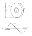
- FIG. 1 is a perspective view which shows an example of a sample
- FIG. 2 is a diagram which shows the characteristic of the shear force of a sample.
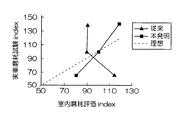
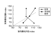
- the result of the simulation described in the third embodiment and the evaluation value of the tire wear obtained from the result of the conventional simulation and the tire wear amount determined from the tire wear amount measured by running on the actual vehicle It is a graph which shows the relationship with the real vehicle abrasion test Index which is an evaluation value regarding abrasion.
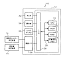
- FIG. 1 shows a tire rubber index calculation system 10 according to the present embodiment.
- the tire rubber index calculation system 10 includes a tire rubber index calculation device 12, a friction energy measurement device 14, and a wear amount measurement device 16.
- the tire rubber index calculation device 12 includes a CPU (Central Processing Unit) 18, a ROM (Read Only Memory) 20, a RAM (Random Access Memory) 22, a nonvolatile memory 24, and an input / output interface ( I / O) 26 includes a computer 30 connected via a bus 28.
- a CPU Central Processing Unit
- ROM Read Only Memory
- RAM Random Access Memory
- I / O input / output interface
- a monitor 32 constituted by a liquid crystal display
- an operation unit 34 constituted by a keyboard, a mouse, and the like
- a hard disk 36 constituted by a hard disk 36
- a communication interface (I / F) 38 Connected to the I / O 26 are a monitor 32 constituted by a liquid crystal display, an operation unit 34 constituted by a keyboard, a mouse, and the like, a hard disk 36, and a communication interface (I / F) 38.
- a friction energy measuring device 14 and a wear amount measuring device 16 are connected to the communication I / F 38.
- the friction energy measuring device 14 measures, for example, the friction energy of the ground contact surface of a disk-like sample made of the same material as the tread portion of the tire for which the rubber index is calculated.
- a device for example, the ground contact portion measuring device for the tire ground contact surface described in Patent Document 1 and Patent Document 2 described above can be used.
- the resolution of the camera that captures the ground contact surface of the sample and the sampling rate of shooting are It is preferable to make it higher than when measuring the frictional energy of the ground contact surface.
- a sample 40 as shown in FIG. 2A is used as the sample.
- the width W is 5 mm or more
- the diameter 2R is less than 80 mm
- the thickness (outer diameter-inner diameter) D of the sample 40 is 5 mm or more.
- FIG. 5B it is preferable to use a sample in which the slope K of the shearing force is negative.
- the wear amount measuring device 16 measures the wear amount of the tire for which the rubber index is calculated.
- a wear test apparatus that measures the amount of wear of a tire by a so-called lambone test as described in Patent Document 1 and Patent Document 3 can be used.
- the friction energy measuring device 14 on which the rubber index calculation target tire is set is instructed to measure the friction energy of the tire that is the rubber index calculation target under a plurality of tire input conditions.
- the types of tire input include, for example, driving force (front / rear force), lateral force (left / right force), braking force, etc. acting on the tire.
- a plurality of tire input conditions are set for each of these tire input types. To do. Below, in order to demonstrate easily, the case where a driving force and a lateral force are set as tire input conditions is demonstrated.
- the friction energy measuring device 14 measures the friction energy of the tire for each of the instructed plural tire input conditions. Thereby, for example, each friction energy when a plurality of different driving forces are applied to the tire and each friction energy when a plurality of different lateral forces are applied to the tire are measured by the friction energy measuring device 14. Each measured friction energy is output to the rubber index calculation device 12.
- a friction energy function indicating the correspondence between tire input and friction energy is calculated for each type of tire input condition. That is, the friction energy function f1 indicating the correspondence between the driving force and the friction energy is calculated based on the friction energy measured by applying a plurality of different driving forces to the tire. The calculation of the friction energy function can be obtained using, for example, the least square method. Similarly, a friction energy function f2 indicating a correspondence relationship between the lateral force and the friction energy is calculated.
- step 104 frequency data indicating the relationship between the tire input measured when the vehicle equipped with the tire for which the rubber index is to be calculated is actually traveled on a predetermined traveling course and the frequency thereof, and the friction energy function obtained in step 102. Based on the above, an expected value of friction energy for each type of tire input is calculated.
- the frequency data is obtained as follows, for example. First, a sensor for measuring the driving force and lateral force input to the tire is attached to the vehicle to travel on the traveling course, and the driving force and lateral force during traveling are measured. Then, the frequency of each input is determined based on the measured driving force and lateral force data. Thereby, the frequency data which shows the relationship between the driving force and lateral force which were measured in the actual vehicle, and these frequency (%) are obtained.
- the obtained frequency data is stored in advance in the hard disk 36, for example.
- the friction energy corresponding to each driving force data when measuring the friction energy of the tire in the frequency data is calculated by the friction energy function f1, respectively, and the calculated frequency is multiplied by the corresponding frequency. , Add all these.
- the expected value Ewd of the frictional energy of the driving force is calculated.
- the type of friction energy of the measured driving force is Ewd 1 , Ewd 2 ,... Ewd n (n is the number of types of friction energy of the driving force), and the frequency is h 1 , h 2.
- the expected value Ewd of the friction energy function of the driving force is calculated by the following equation.
- Ewd Ewd 1 ⁇ h 1 + Ewd 2 ⁇ h 2 +, Ewd n ⁇ h n (1)
- step 106 the expected value Ew of the frictional energy of the driving force obtained in step 104 and the expected value Ewc of the frictional energy of the lateral force are added to calculate the expected value Ew of the total frictional energy.
- step 108 based on the expected value Ew of the frictional energy obtained in step 106, measurement conditions for measuring the frictional energy of the disk-shaped sample made of the same material as the tread portion of the tire for which the rubber index is to be calculated are determined.
- the lateral force corresponding to the expected value Ewc of the driving force and the lateral frictional energy Ewc corresponding to the expected value Ewd of the frictional energy of the driving force obtained in Step 106 is obtained as the friction energy function.
- the obtained driving force and lateral force are obtained using f1 and f2, respectively, and set as measurement conditions (sample input conditions) for measuring the friction energy of the sample.
- step 110 the friction energy measuring device 14 in which the sample is set is instructed to measure the friction energy of the sample under the measurement conditions set in step 108.
- the friction energy measuring device 14 measures the friction energy of the sample under the measurement conditions instructed from the rubber index calculating device 12.
- the measurement of the frictional energy of the sample is performed by measuring the shearing force and the amount of slip applied to the ground contact surface of the sample and obtaining the frictional energy based on these.
- the measured friction energy is output to the rubber index calculation device 12.
- step 112 it is determined whether or not the expected value Ew of the frictional energy of the tire obtained in step 106 matches the frictional energy of the sample measured by the frictional energy measuring device 14 in step 110. Returning to step 108, the measurement conditions are changed, and the same processing is repeated. If the expected value Ew of the frictional energy of the tire matches the frictional energy of the sample, the process proceeds to step 114. In this way, the process of changing the measurement conditions and measuring the frictional energy of the sample is repeated until the expected value Ew of the frictional energy of the tire matches the frictional energy of the sample.
- step 114 a measurement condition in which the expected value Ew of the frictional energy of the tire matches the frictional energy of the sample is set as a measurement condition for measuring the wear amount of the sample.
- step 116 the amount of wear is measured under the measurement conditions set in step 114, that is, measurement conditions (driving force and lateral force) when the expected value Ew of the tire friction energy and the friction energy of the sample coincide. Then, the wear amount measuring device 16 is instructed. Accordingly, the wear amount measuring device 16 measures the wear amount m of the sample under the measurement conditions instructed by the rubber index calculating device 12. The measured wear amount is output to the rubber index calculation device 12.
- the rubber index G is calculated based on the calculated expected friction energy value Ew of the sample and the wear amount m, and the calculation result is output to the monitor 32 or the hard disk 36, for example, and the calculation result is displayed on the monitor 32. Or stored in the hard disk 36.
- the friction energy of the sample is measured by the friction energy measuring device 14 that measures the frictional energy of the sample based on the shear force and the slip amount of the tire contact surface, and the measured friction energy of the sample matches the friction energy of the tire.
- the measurement conditions of the sample are matched, and the rubber index is calculated based on the wear amount of the sample measured under the measurement condition and the friction energy of the sample. For this reason, compared with the case where the friction energy averaged based on the axial force as before is calculated, the friction energy can be measured with high accuracy, and the rubber index can be calculated with high accuracy.
- the friction energy function is obtained for each type of tire input condition, and the rubber index is calculated after obtaining the expected value of the total tire friction energy.
- the rubber index is calculated for each tire input condition. The case where the index is calculated and the expected value of the rubber index is calculated from these rubber indexes will be described.
- step 200 shown in FIG. 4 as in step 100 of FIG. 3, the rubber index calculation target tire is set so as to measure the friction energy of the rubber index calculation target tire under a plurality of tire input conditions.
- the friction energy measuring device 14 is instructed.
- the friction energy measuring device 14 measures the friction energy of the tire for each of the plurality of tire input conditions instructed from the rubber index calculating device 12. Thereby, for example, each friction energy when a plurality of different driving forces are applied to the tire and each friction energy when a plurality of different lateral forces are applied to the tire are measured by the friction energy measuring device 14. Each measured friction energy is output to the rubber index calculation device 12.
- step 202 one of the plurality of tire input conditions for which the frictional energy is obtained in step 200 is set as a measurement condition for measuring the frictional energy of the sample.
- step 204 the friction energy measuring device 14 in which the sample is set is instructed to measure the friction energy of the sample under the measurement conditions set in step 202. Thereby, the friction energy measuring device 14 measures the friction energy of the sample under the measurement conditions instructed from the rubber index calculating device 12. The measured friction energy is output to the rubber index calculation device 12.
- step 206 it is determined whether or not the frictional energy of the tire obtained in step 200 and the frictional energy of the sample measured by the frictional energy measuring device 14 in step 204 match. If they do not match, go to step 202. Return to change the measurement conditions and repeat the same process as above. When the friction energy of the tire and the friction energy of the sample coincide with each other, the process proceeds to step 208, and the measurement condition is stored in the hard disk 36. In this way, the process of changing the measurement conditions and measuring the friction energy of the sample is repeated until the friction energy of the tire matches the friction energy of the sample.
- step 210 it is determined whether or not the processing in steps 202 to 208 has been executed for all the tire input conditions measured in step 200. If so, the process proceeds to step 212, and tires not yet executed. If there is an input condition, the process returns to step 202 and the same processing as described above is repeated. Thereby, the measurement conditions for measuring the wear amount of the sample corresponding to each of the plurality of tire input conditions measured in step 200 are set.
- step 212 the wear amount measuring device 16 is instructed to measure the wear amount under the measurement conditions (driving force and lateral force) when the tire friction energy and the sample friction energy match for each tire input condition. To do.
- the wear amount measuring device 16 measures the wear amount of the sample under each measurement condition instructed by the rubber index calculating device 12. Each measured wear amount is output to the rubber index calculation device 12.
- step 214 for each tire input condition, a rubber index is calculated based on the friction energy and wear amount of the sample.
- a rubber index function indicating the correspondence between the tire input and the rubber index is calculated for each type of tire input condition. That is, the rubber index function f3 indicating the correspondence between the driving force and the rubber index is calculated based on each rubber index calculated for the tire input conditions of a plurality of driving forces.
- the rubber index function f3 can be calculated using, for example, the least square method.
- a rubber index function f4 indicating the correspondence between the lateral force and the rubber index is calculated.
- step 218 the frequency data indicating the relationship between the tire input measured when the vehicle equipped with the tire for which the rubber index is to be calculated is actually traveled on a predetermined traveling course and the frequency thereof, and the tire input condition obtained in step 216.
- the expected value of the rubber index is calculated for each type of tire input condition based on the rubber index function for each type.
- the rubber index corresponding to each driving force data when the frictional energy of the tire is measured among the frequency data is calculated by the rubber index function f3, and the calculated frequency is multiplied by the corresponding frequency. , Add all these.
- the expected value Gd of the rubber index of the driving force is calculated.
- the type of rubber index driving force Gd 1, Gd 2, ⁇ Gd n (n is the number of types of rubber index driving force), and the frequency thereof h 1, h 2 ⁇ h n (n Is the number of types of rubber index of the driving force) the expected value Gd of the rubber index of the driving force is calculated by the following equation.
- Gd Gd 1 ⁇ h 1 + Gd 2 ⁇ h 2 +,...
- step 220 the expected value G of the total rubber index is calculated by adding the expected value Gd of the rubber index of the driving force obtained in step 218 and the expected value Gc of the rubber index of the lateral force.
- the friction energy of the sample is measured by the friction energy measuring device 14 that measures the frictional energy of the sample based on the shear force and the slip amount of the tire contact surface, and the measured friction energy of the sample matches the friction energy of the tire.
- the measurement conditions of the sample are matched, and the rubber index is calculated based on the wear amount of the sample measured under the measurement condition and the friction energy of the sample. For this reason, compared with the case where the friction energy averaged based on the axial force as before is calculated, the friction energy can be measured with high accuracy, and the rubber index can be calculated with high accuracy.
- the frictional energy of the sample is measured by the frictional energy measuring device 14, but in this embodiment, the frictional energy of the ground contact surface of the sample is finitely limited using a sample model in which the sample is divided into a plurality of elements.
- FEM element method
- the rubber index calculation device is the same as that of the first embodiment, and thus description thereof is omitted.
- Steps 100 to 106 are the same as the processing shown in FIG.
- step 108A based on the expected value Ew of the frictional energy obtained in step 106, a simulation condition for simulating the frictional energy of the disk-shaped sample made of the same material as the tread portion of the tire for which the rubber index is to be calculated is determined.
- the lateral force corresponding to the expected value Ewc of the driving force and the lateral frictional energy Ewc corresponding to the expected value Ewd of the frictional energy of the driving force obtained in Step 106 is obtained as the friction energy function.
- the obtained driving force and lateral force are obtained using f1 and f2, respectively, and set as simulation conditions (sample input conditions) for simulating the friction energy of the sample.
- step 110A the frictional energy of the sample is simulated under the simulation conditions set in step 106.
- a sample model in which a sample is divided into a plurality of elements is created, and a rolling analysis is performed on the sample model under the simulation conditions set in step 106 by a known method using a finite element method.
- the frictional energy of the sample is calculated based on the obtained shearing force and slip amount.
- Steps 112 to 118 are the same as the process shown in FIG. 3 except that the frictional energy of the tire used for the process is the frictional energy calculated by the simulation, and the description thereof will be omitted.
- the friction energy of the sample is calculated based on the shear force and the slip amount of the tire contact surface obtained by the simulation, and the calculated friction energy of the sample matches the friction energy of the tire.
- the rubber index is calculated based on the sample wear amount and the sample friction energy measured under the sample simulation conditions. For this reason, compared with the case where the friction energy averaged based on the axial force as before is calculated, the friction energy can be measured with high accuracy, and the rubber index can be calculated with high accuracy.
- the friction energy of the sample is measured by the friction energy measuring device 14, but in this embodiment, the friction energy of the ground contact surface of the sample is finitely limited using a sample model in which the sample is divided into a plurality of elements. A case of obtaining by simulation using the element method will be described.
- the rubber index calculation device is the same as that of the first embodiment, and thus description thereof is omitted.
- Step 200 shown in FIG. 6 is the same as step 200 in FIG. 6
- step 202A one of the plurality of tire input conditions for which the frictional energy is obtained in step 200 is set as a simulation condition for simulating the frictional energy of the sample.
- step 204A similar to step 108A in FIG. 5, the frictional energy of the sample is calculated by simulation under the simulation conditions set in step 202.
- step 206 it is determined whether or not the tire friction energy obtained in step 200 matches the sample friction energy calculated in step 204. If not, the process returns to step 202A to change the measurement conditions. Then, the same processing as described above is repeated. When the friction energy of the tire and the friction energy of the sample coincide with each other, the process proceeds to step 208A, and the simulation conditions are stored in the hard disk 36. In this manner, the process of simulating the friction energy of the sample is repeated by changing the simulation conditions until the friction energy of the tire matches the friction energy of the sample.
- Step 210 it is determined whether or not the processing in Steps 202A to 208A has been executed for all the tire input conditions measured in Step 200. If so, the process proceeds to Step 212, and tires that have not been executed yet. If there is an input condition, the process returns to step 202A and the same processing as described above is repeated. Thereby, the measurement conditions for measuring the wear amount of the sample corresponding to each of the plurality of tire input conditions measured in step 200 are set.
- Steps 212 to 220 are the same as the process shown in FIG. 4 except that the friction energy of the tire used for the process is the friction energy calculated by the simulation, and thus the description thereof is omitted.
- the frictional energy of the sample is calculated by simulation based on the shearing force and the slip amount of the tire contact surface, and the simulation of the sample is performed so that the calculated frictional energy of the sample matches the frictional energy of the tire.
- the rubber index is calculated based on the wear amount of the sample and the frictional energy of the sample measured under the simulation conditions. For this reason, compared with the case where the friction energy averaged based on the axial force as before is calculated, the friction energy can be measured with high accuracy, and the rubber index can be calculated with high accuracy.
- FIG. 10 shows an indoor wear evaluation index that is an evaluation value related to tire wear obtained from the simulation results described in the first embodiment and the results of the conventional simulation, the amount of tire wear measured by running an actual vehicle, and the like.
- the relationship with the actual vehicle wear test Index which is an evaluation value related to the wear of the tire obtained from the above, is shown.
- the vehicle used in the running test using an actual vehicle is a truck with a front wheel having one steering axis and a rear wheel having two driving axes. It drove on condition of h, and measured the amount of wear. From this measurement result, an actual vehicle wear evaluation index was obtained.
- each of the simulations was performed by the method described in the first embodiment and the conventional method under the same conditions as the driving test using an actual vehicle, and the indoor wear evaluation index related to tire wear was obtained based on the results.
- the simulation of the conventional method is a method for obtaining the wear amount and the like while keeping the tire slip ratio constant.
- the inclination is opposite to the inclination in the ideal case.
- the simulation result according to the first embodiment of the present invention the inclination is the same as in the ideal case.
- FIGS. 11 to 13 show an indoor wear evaluation index that is an evaluation value related to tire wear obtained from the simulation results described in the second to fourth embodiments and the results of the conventional simulation, and an actual vehicle.
- the simulation results according to the second to fourth embodiments also have the same inclination as the ideal case.
- the relationship between the indoor wear evaluation index and the actual vehicle wear evaluation index can be brought close to an ideal state, and as a result, the rubber index can be calculated with high accuracy. I found that I can do it.
Landscapes
- Engineering & Computer Science (AREA)
- Mechanical Engineering (AREA)
- Physics & Mathematics (AREA)
- General Physics & Mathematics (AREA)
- General Health & Medical Sciences (AREA)
- Health & Medical Sciences (AREA)
- Life Sciences & Earth Sciences (AREA)
- Chemical & Material Sciences (AREA)
- Analytical Chemistry (AREA)
- Biochemistry (AREA)
- Immunology (AREA)
- Pathology (AREA)
- General Engineering & Computer Science (AREA)
- Automation & Control Theory (AREA)
- Computer Hardware Design (AREA)
- Tires In General (AREA)
Priority Applications (5)
| Application Number | Priority Date | Filing Date | Title |
|---|---|---|---|
| CN2010800374090A CN102483372B (zh) | 2009-08-25 | 2010-08-25 | 轮胎的橡胶指数计算方法及其装置 |
| IN2406DEN2012 IN2012DN02406A (https=) | 2009-08-25 | 2010-08-25 | |
| KR1020127007006A KR101346991B1 (ko) | 2009-08-25 | 2010-08-25 | 타이어의 고무 인덱스 산출 방법, 장치 및 컴퓨터 판독가능 기억 매체 |
| US13/391,999 US9423320B2 (en) | 2009-08-25 | 2010-08-25 | Tire rubber index calculating method, device, and computer-readable storage medium |
| EP10811926.4A EP2472243B1 (en) | 2009-08-25 | 2010-08-25 | Tire rubber index calculating method, device, and program |
Applications Claiming Priority (2)
| Application Number | Priority Date | Filing Date | Title |
|---|---|---|---|
| JP2009194161A JP5261321B2 (ja) | 2009-08-25 | 2009-08-25 | タイヤのゴムインデックス算出方法、装置、及びプログラム |
| JP2009-194161 | 2009-08-25 |
Publications (1)
| Publication Number | Publication Date |
|---|---|
| WO2011024877A1 true WO2011024877A1 (ja) | 2011-03-03 |
Family
ID=43627977
Family Applications (1)
| Application Number | Title | Priority Date | Filing Date |
|---|---|---|---|
| PCT/JP2010/064423 Ceased WO2011024877A1 (ja) | 2009-08-25 | 2010-08-25 | タイヤのゴムインデックス算出方法、装置、及びプログラム |
Country Status (7)
| Country | Link |
|---|---|
| US (1) | US9423320B2 (https=) |
| EP (1) | EP2472243B1 (https=) |
| JP (1) | JP5261321B2 (https=) |
| KR (1) | KR101346991B1 (https=) |
| CN (1) | CN102483372B (https=) |
| IN (1) | IN2012DN02406A (https=) |
| WO (1) | WO2011024877A1 (https=) |
Families Citing this family (19)
| Publication number | Priority date | Publication date | Assignee | Title |
|---|---|---|---|---|
| DE102008049754A1 (de) * | 2008-09-30 | 2010-04-08 | Continental Automotive Gmbh | Verfahren und Vorrichtung zur Verschleißdiagnose eines Kraftfahrzeugs |
| JP6112870B2 (ja) * | 2013-01-11 | 2017-04-12 | 株式会社ブリヂストン | タイヤの摩耗予測方法、及びタイヤの摩耗予測プログラム |
| CN103776639B (zh) * | 2014-02-19 | 2014-11-05 | 吉林大学 | 一种全速度范围轮胎力学特性的试验方法及装置 |
| JP6790875B2 (ja) * | 2017-01-27 | 2020-11-25 | 住友ゴム工業株式会社 | タイヤ摩耗性能予測方法 |
| JP6959849B2 (ja) * | 2017-12-07 | 2021-11-05 | Toyo Tire株式会社 | 接地面観察方法 |
| JP6976833B2 (ja) * | 2017-12-14 | 2021-12-08 | 株式会社ブリヂストン | 摩耗量予測方法、摩耗量予測装置、及び摩耗量予測プログラム |
| US11987119B2 (en) * | 2018-03-02 | 2024-05-21 | Volvo Truck Corporation | Device, method, and program for tire failure detection, and computer-readable recording medium recording tire failure detection program |
| CN111412848B (zh) * | 2019-01-04 | 2022-04-05 | 宇通客车股份有限公司 | 一种轮胎磨损检测方法及装置 |
| AU2020220060A1 (en) | 2019-08-30 | 2021-03-18 | The Goodyear Tire & Rubber Company | Method for extracting changes in tyre characteristics |
| AU2020220054A1 (en) | 2019-08-30 | 2021-03-18 | The Goodyear Tire & Rubber Company | Tire wear state estimation system and method employing footprint length |
| US11981163B2 (en) | 2019-08-30 | 2024-05-14 | The Goodyear Tire & Rubber Company | Tire wear state estimation system and method employing footprint shape factor |
| WO2021128227A1 (zh) * | 2019-12-26 | 2021-07-01 | 山东玲珑轮胎股份有限公司 | 一种轮胎磨耗性能数值评估和优化方法 |
| JP7497577B2 (ja) * | 2020-02-21 | 2024-06-11 | 住友ゴム工業株式会社 | タイヤ摩耗性能予測方法 |
| KR102401493B1 (ko) * | 2020-11-19 | 2022-05-24 | 넥센타이어 주식회사 | 타이어 예상마일리지 추정방법 및 이를 이용한 타이어 예상마일리지의 추정이 가능한 내마모 시험장치 |
| US12220946B2 (en) | 2021-06-08 | 2025-02-11 | The Goodyear Tire & Rubber Company | Tire replacement forecasting system and method |
| FR3127835A1 (fr) * | 2021-10-06 | 2023-04-07 | Psa Automobiles Sa | Procede et systeme pour determiner des donnees caracterisant l’usure des pneumatiques d’un vehicule automobile |
| US12263704B2 (en) | 2021-12-06 | 2025-04-01 | The Goodyear Tire & Rubber Company | Tire irregular wear detection system and method |
| EP4296880A1 (en) * | 2022-06-24 | 2023-12-27 | Bridgestone Corporation | Evaluating wear of a tire with a non-axisymmetric tread pattern |
| US12589618B2 (en) | 2022-11-11 | 2026-03-31 | The Goodyear Tire & Rubber Company | Method and system for monitoring tire inflation pressure |
Citations (8)
| Publication number | Priority date | Publication date | Assignee | Title |
|---|---|---|---|---|
| JPH11326144A (ja) * | 1998-05-08 | 1999-11-26 | Bridgestone Corp | タイヤ摩耗寿命予測方法 |
| JP2001047822A (ja) * | 1999-08-10 | 2001-02-20 | Toyo Tire & Rubber Co Ltd | 転動タイヤの摩擦エネルギー解析方法 |
| JP3277155B2 (ja) | 1998-05-08 | 2002-04-22 | 株式会社ブリヂストン | タイヤ摩耗寿命予測方法 |
| JP2003050190A (ja) | 2001-08-03 | 2003-02-21 | Bridgestone Corp | タイヤ摩耗寿命予測方法 |
| JP3406643B2 (ja) | 1993-06-30 | 2003-05-12 | 株式会社ブリヂストン | タイヤ踏面の接地部測定装置及びタイヤ踏面の接地部測定方法 |
| JP2006232011A (ja) * | 2005-02-23 | 2006-09-07 | Yokohama Rubber Co Ltd:The | タイヤの摩耗予測方法、タイヤの設計方法、タイヤの製造方法、タイヤの摩耗予測システム及びプログラム |
| JP2006242697A (ja) | 2005-03-02 | 2006-09-14 | Bridgestone Corp | 摩耗試験方法および摩耗試験装置 |
| JP2008082914A (ja) * | 2006-09-28 | 2008-04-10 | Yokohama Rubber Co Ltd:The | タイヤ摩耗寿命予測方法 |
Family Cites Families (3)
| Publication number | Priority date | Publication date | Assignee | Title |
|---|---|---|---|---|
| JP3320653B2 (ja) * | 1998-05-08 | 2002-09-03 | 株式会社ブリヂストン | タイヤ摩耗寿命予測方法 |
| US6269690B1 (en) | 1998-05-08 | 2001-08-07 | Bridgestone Corporation | Method for estimating a tire wear life |
| CN101183402B (zh) * | 2006-11-13 | 2012-07-25 | 韩国轮胎株式会社 | 轮胎花纹的实际磨损预测方法 |
-
2009
- 2009-08-25 JP JP2009194161A patent/JP5261321B2/ja active Active
-
2010
- 2010-08-25 CN CN2010800374090A patent/CN102483372B/zh active Active
- 2010-08-25 WO PCT/JP2010/064423 patent/WO2011024877A1/ja not_active Ceased
- 2010-08-25 KR KR1020127007006A patent/KR101346991B1/ko active Active
- 2010-08-25 US US13/391,999 patent/US9423320B2/en active Active
- 2010-08-25 EP EP10811926.4A patent/EP2472243B1/en active Active
- 2010-08-25 IN IN2406DEN2012 patent/IN2012DN02406A/en unknown
Patent Citations (8)
| Publication number | Priority date | Publication date | Assignee | Title |
|---|---|---|---|---|
| JP3406643B2 (ja) | 1993-06-30 | 2003-05-12 | 株式会社ブリヂストン | タイヤ踏面の接地部測定装置及びタイヤ踏面の接地部測定方法 |
| JPH11326144A (ja) * | 1998-05-08 | 1999-11-26 | Bridgestone Corp | タイヤ摩耗寿命予測方法 |
| JP3277155B2 (ja) | 1998-05-08 | 2002-04-22 | 株式会社ブリヂストン | タイヤ摩耗寿命予測方法 |
| JP2001047822A (ja) * | 1999-08-10 | 2001-02-20 | Toyo Tire & Rubber Co Ltd | 転動タイヤの摩擦エネルギー解析方法 |
| JP2003050190A (ja) | 2001-08-03 | 2003-02-21 | Bridgestone Corp | タイヤ摩耗寿命予測方法 |
| JP2006232011A (ja) * | 2005-02-23 | 2006-09-07 | Yokohama Rubber Co Ltd:The | タイヤの摩耗予測方法、タイヤの設計方法、タイヤの製造方法、タイヤの摩耗予測システム及びプログラム |
| JP2006242697A (ja) | 2005-03-02 | 2006-09-14 | Bridgestone Corp | 摩耗試験方法および摩耗試験装置 |
| JP2008082914A (ja) * | 2006-09-28 | 2008-04-10 | Yokohama Rubber Co Ltd:The | タイヤ摩耗寿命予測方法 |
Also Published As
| Publication number | Publication date |
|---|---|
| JP5261321B2 (ja) | 2013-08-14 |
| CN102483372B (zh) | 2013-07-31 |
| EP2472243A4 (en) | 2016-01-27 |
| CN102483372A (zh) | 2012-05-30 |
| EP2472243A1 (en) | 2012-07-04 |
| JP2011047675A (ja) | 2011-03-10 |
| EP2472243B1 (en) | 2018-02-21 |
| KR20120050486A (ko) | 2012-05-18 |
| IN2012DN02406A (https=) | 2015-08-21 |
| US9423320B2 (en) | 2016-08-23 |
| KR101346991B1 (ko) | 2014-01-02 |
| US20120197548A1 (en) | 2012-08-02 |
Similar Documents
| Publication | Publication Date | Title |
|---|---|---|
| JP5261321B2 (ja) | タイヤのゴムインデックス算出方法、装置、及びプログラム | |
| JP5534588B2 (ja) | タイヤのゴムインデックス算出方法、装置及びプログラム | |
| CN112533775B (zh) | 胎面磨损监测系统和方法 | |
| JP6803448B1 (ja) | 最大摩擦係数推定システムおよび最大摩擦係数推定方法 | |
| CN112818563B (zh) | 一种基于摩擦接触面预估的路面抗滑性能评价方法 | |
| CN104870970A (zh) | 用于室内轮胎测试的可扩展车辆模型 | |
| CN102252659A (zh) | 基于激光传感器的车载式道路路面坡度测量方法 | |
| JP2020020796A (ja) | 屋内タイヤ試験に対するスケール変更可能な車両モデル | |
| JP2012037280A (ja) | タイヤ性能シミュレーション方法、タイヤ性能シミュレーション装置、及びタイヤ性能シミュレーションプログラム | |
| CN111623997A (zh) | 车辆试验场的构建方法、装置、电子设备及可读存储介质 | |
| CN106198044B (zh) | 电动汽车续航里程测试方法及装置 | |
| CN116992698B (zh) | 一种车辆板簧疲劳试验模拟检测方法、系统及存储介质 | |
| JP4752704B2 (ja) | タイヤ摩耗寿命予測方法 | |
| Holtschulze et al. | A simplified tyre model for intelligent tyres | |
| Liu et al. | Modelling wear of truck tyres under high slip | |
| JP2001047822A (ja) | 転動タイヤの摩擦エネルギー解析方法 | |
| JP2016134146A (ja) | タイヤのシミュレーション方法及びシミュレーション装置 | |
| CN120688296A (zh) | 轮胎磨耗寿命里程的确定方法及装置 | |
| CN114999175A (zh) | 基于光纤光栅阵列传感的车辆识别方法、装置与设备 | |
| Luty | The μ-PW friction Tester as a new device to assess the value of friction coefficient between vehicle wheels and the road surface at the traffic accident scene | |
| JP6112870B2 (ja) | タイヤの摩耗予測方法、及びタイヤの摩耗予測プログラム | |
| JP2025066297A (ja) | タイヤ摩耗量の予測シミュレーション方法および装置 | |
| KR101218796B1 (ko) | 노면 효과를 고려한 타이어 마찰에너지 분석방법 | |
| CN120911098A (zh) | 轮胎冰地制动力评估方法及装置 | |
| JP2025094993A (ja) | タイヤ性能予測シミュレーション方法および装置 |
Legal Events
| Date | Code | Title | Description |
|---|---|---|---|
| WWE | Wipo information: entry into national phase |
Ref document number: 201080037409.0 Country of ref document: CN |
|
| 121 | Ep: the epo has been informed by wipo that ep was designated in this application |
Ref document number: 10811926 Country of ref document: EP Kind code of ref document: A1 |
|
| NENP | Non-entry into the national phase |
Ref country code: DE |
|
| WWE | Wipo information: entry into national phase |
Ref document number: 2010811926 Country of ref document: EP |
|
| ENP | Entry into the national phase |
Ref document number: 20127007006 Country of ref document: KR Kind code of ref document: A |
|
| WWE | Wipo information: entry into national phase |
Ref document number: 2406/DELNP/2012 Country of ref document: IN |
|
| WWE | Wipo information: entry into national phase |
Ref document number: 13391999 Country of ref document: US |