WO2011024643A1 - 可搬型照明装置 - Google Patents
可搬型照明装置 Download PDFInfo
- Publication number
- WO2011024643A1 WO2011024643A1 PCT/JP2010/063552 JP2010063552W WO2011024643A1 WO 2011024643 A1 WO2011024643 A1 WO 2011024643A1 JP 2010063552 W JP2010063552 W JP 2010063552W WO 2011024643 A1 WO2011024643 A1 WO 2011024643A1
- Authority
- WO
- WIPO (PCT)
- Prior art keywords
- main body
- rotating member
- portable
- apparatus main
- illumination
- Prior art date
- Legal status (The legal status is an assumption and is not a legal conclusion. Google has not performed a legal analysis and makes no representation as to the accuracy of the status listed.)
- Ceased
Links
Images











Classifications
-
- F—MECHANICAL ENGINEERING; LIGHTING; HEATING; WEAPONS; BLASTING
- F21—LIGHTING
- F21L—LIGHTING DEVICES OR SYSTEMS THEREOF, BEING PORTABLE OR SPECIALLY ADAPTED FOR TRANSPORTATION
- F21L4/00—Electric lighting devices with self-contained electric batteries or cells
-
- F—MECHANICAL ENGINEERING; LIGHTING; HEATING; WEAPONS; BLASTING
- F21—LIGHTING
- F21S—NON-PORTABLE LIGHTING DEVICES; SYSTEMS THEREOF; VEHICLE LIGHTING DEVICES SPECIALLY ADAPTED FOR VEHICLE EXTERIORS
- F21S9/00—Lighting devices with a built-in power supply; Systems employing lighting devices with a built-in power supply
- F21S9/02—Lighting devices with a built-in power supply; Systems employing lighting devices with a built-in power supply the power supply being a battery or accumulator
- F21S9/03—Lighting devices with a built-in power supply; Systems employing lighting devices with a built-in power supply the power supply being a battery or accumulator rechargeable by exposure to light
- F21S9/037—Lighting devices with a built-in power supply; Systems employing lighting devices with a built-in power supply the power supply being a battery or accumulator rechargeable by exposure to light the solar unit and the lighting unit being located within or on the same housing
-
- F—MECHANICAL ENGINEERING; LIGHTING; HEATING; WEAPONS; BLASTING
- F21—LIGHTING
- F21V—FUNCTIONAL FEATURES OR DETAILS OF LIGHTING DEVICES OR SYSTEMS THEREOF; STRUCTURAL COMBINATIONS OF LIGHTING DEVICES WITH OTHER ARTICLES, NOT OTHERWISE PROVIDED FOR
- F21V21/00—Supporting, suspending, or attaching arrangements for lighting devices; Hand grips
- F21V21/06—Bases for movable standing lamps; Fixing standards to the bases
-
- F—MECHANICAL ENGINEERING; LIGHTING; HEATING; WEAPONS; BLASTING
- F21—LIGHTING
- F21V—FUNCTIONAL FEATURES OR DETAILS OF LIGHTING DEVICES OR SYSTEMS THEREOF; STRUCTURAL COMBINATIONS OF LIGHTING DEVICES WITH OTHER ARTICLES, NOT OTHERWISE PROVIDED FOR
- F21V21/00—Supporting, suspending, or attaching arrangements for lighting devices; Hand grips
- F21V21/08—Devices for easy attachment to any desired place, e.g. clip, clamp, magnet
- F21V21/088—Clips; Clamps
-
- F—MECHANICAL ENGINEERING; LIGHTING; HEATING; WEAPONS; BLASTING
- F21—LIGHTING
- F21V—FUNCTIONAL FEATURES OR DETAILS OF LIGHTING DEVICES OR SYSTEMS THEREOF; STRUCTURAL COMBINATIONS OF LIGHTING DEVICES WITH OTHER ARTICLES, NOT OTHERWISE PROVIDED FOR
- F21V21/00—Supporting, suspending, or attaching arrangements for lighting devices; Hand grips
- F21V21/14—Adjustable mountings
- F21V21/30—Pivoted housings or frames
-
- F—MECHANICAL ENGINEERING; LIGHTING; HEATING; WEAPONS; BLASTING
- F21—LIGHTING
- F21Y—INDEXING SCHEME ASSOCIATED WITH SUBCLASSES F21K, F21L, F21S and F21V, RELATING TO THE FORM OR THE KIND OF THE LIGHT SOURCES OR OF THE COLOUR OF THE LIGHT EMITTED
- F21Y2115/00—Light-generating elements of semiconductor light sources
- F21Y2115/10—Light-emitting diodes [LED]
Definitions
- the present invention relates to a portable lighting device configured to be portable, and more particularly to a portable lighting device including a solar cell panel.
- the portable lighting device disclosed in the publication includes a solar cell panel and LED (Light-Emitting Diode) lamps on the front and back of a trunk-like device body, and a storage battery inside the device body.
- the main body is made portable by attaching a hand holder or shoulder.
- sunlight is received by a solar battery panel to store electric power in the storage battery, and the electric power stored in the storage battery is supplied to the LED lighting lamp so that the LED lighting lamp is Operates to illuminate the surroundings.
- the portable lighting device disclosed in the above publication is basically intended to be mounted on the floor because the main body of the device is trunk-shaped and large. Therefore, the function as an illuminating device is still inadequate, and it is not configured to sufficiently illuminate the vicinity from a high place.
- the above publication also discloses a usage mode in which the LED illumination lamp is detached from the apparatus main body, but in that case, the apparatus main body and the LED illumination lamp are connected by a cord, and not necessarily It cannot be said that it is easy to handle.
- the present invention has been made to solve the above-described problems, and an object of the present invention is to provide a portable lighting device excellent in handleability that can be used for various applications.
- a portable illumination device includes a device main body having a front surface and a back surface, a solar cell panel disposed on the front surface of the device main body, and power generated by the solar cell panel provided in the device main body.
- a rotating member that is rotatably attached to the apparatus main body, can serve as a stand for supporting the apparatus main body during charging, and can serve as an arm for suspending the apparatus main body during illumination.
- the portable illumination device controls the operation of the illumination unit based on a position detection unit that detects the position of the rotation member and position information of the rotation member detected by the position detection unit. It is preferable to further include a control unit.
- the device main body has a box-like shape, and in that case, the rotating member is disposed on the opposite side surface of the device main body. It is preferable to rotate around the apparatus main body by being attached.
- control unit is configured to supply power from the storage battery to the lighting unit when the rotating member is located on the front side of the device main body.
- control unit determines the amount of power supplied from the storage battery to the lighting unit when the rotating member is located on the front side of the device main body. It is preferable to control variably according to the position of the rotating member, and thereby adjust the illuminance of the illumination unit variably according to the position of the rotating member.
- the portable illumination device further includes an operation unit that allows the operation of the illumination unit to be switched regardless of the position of the rotating member.
- the control unit supplies power generated by the solar cell panel to the storage battery when the rotating member is located on the back side of the device body. It is preferable to control the charging operation and to control the storage battery so that the power generated by the solar cell panel is not charged when the rotating member is located on the front side of the apparatus main body.
- the rotating member is attached to the apparatus main body so as to be able to go around the apparatus main body.
- the rotating member can be held by the device main body at a predetermined position on a circular orbit that rotates around the device main body. .
- the portable illumination device is configured as follows. That is, the rotating member is attached to the shaft portion so as to be movable along the extending direction of the shaft portion, and rotates as the shaft portion rotates. And an elastic biasing member that elastically biases the latch portion toward the device main body, an insertion hole through which the shaft portion is inserted is provided in the device main body, and the device main body of the latch portion is provided in the device main body. A first engaging portion is provided at the facing portion, and a second engaging portion capable of engaging with the first engaging portion is provided at a portion facing the latch portion of the apparatus main body.
- the rotating member is held by the apparatus main body by the first engaging portion engaging the second engaging portion based on the elastic force of the elastic biasing member, The first engaging portion is disengaged from the second engaging portion against the elastic force of the elastic urging member, so that the rotating member is not held by the apparatus main body.
- the first portion of the latch portion facing the device main body is located at a position on the circumference of the first virtual circle centered on the shaft portion.
- a plurality of the first engaging portions are provided at equal intervals along the circumferential direction of the virtual circle, and the same diameter as the first virtual circle, with the insertion hole as a center, at the portion facing the latch portion of the apparatus main body If the same number of the second engaging portions as the first engaging portions are provided at equal intervals along the circumferential direction of the second virtual circle at positions on the circumference of the second virtual circle, It is also possible to hold the rotating member stepwise by the apparatus body on a circular orbit that rotates around the apparatus body.
- the elastic biasing member is configured by a coil spring that is extrapolated to the shaft portion, and in that case, the first engagement portion.
- one of the second engaging portions is constituted by a hemispherical protruding portion protruding along the extending direction of the shaft portion, and the other of the first engaging portion and the second engaging portion is It is preferable that the concave portion is recessed along the extending direction of the shaft portion or a hole portion penetrating along the extending direction of the shaft portion.
- the latch portion is configured by a metal member, and the portion of the device main body provided with the insertion hole and the second engagement portion is provided. It is preferable that it is made of a metal member.
- a charge state display unit for displaying whether or not the battery is in a charged state is provided on the outer surface of a portion excluding the front surface and the back surface of the device body. It is preferable.
- a remaining amount display portion for displaying the state of the remaining amount of the storage battery is provided on the outer surface of the portion of the device main body excluding the front surface and the back surface. It is preferable.
- the portable lighting device according to the present invention further includes a volume knob for adjusting the output of the lighting unit.
- a waterproof cap can be attached to the device main body at the portion where the volume knob is provided.
- the portable lighting device according to the present invention further includes an external output terminal that allows the electric power stored in the storage battery to be output to the outside.
- an external output terminal that allows the electric power stored in the storage battery to be output to the outside.
- a waterproof cap can be attached to the device main body at the portion where the external output terminal is provided.
- the light source included in the illumination unit is preferably an LED.
- the rotating member can be a handle for holding by hand during transportation.
- FIG. 17A It is a figure which shows the state by which the waterproof cap was attached to the part in which the external output terminal of the portable illuminating device in embodiment of this invention was provided. It is a figure which shows the functional block of the portable illuminating device in embodiment of this invention. It is a schematic diagram for demonstrating how the portable illuminating device in embodiment of this invention operate
- FIG. 20A It is a figure which shows the use condition in the case of using the portable illuminating device in embodiment of this invention hanging on a wall surface. It is a figure which shows the operation state of the illumination unit in the use condition shown to FIG. 18A. It is a figure which shows the other use condition at the time of hanging and using the portable illuminating device in embodiment of this invention on a wall surface. It is a figure which shows the operation state of the illumination unit in the use condition shown to FIG. 19A. It is a figure which shows the other use condition in the case of using the portable illuminating device in embodiment of this invention hanging on a wall surface. It is a figure which shows the operation state of the illumination unit in the use condition shown to FIG. 20A.
- the portable lighting device in the embodiment described below is intended to be charged by receiving sunlight in the daytime and used as a lighting device indoors or outdoors at night. It is configured not only to be used for leisure and disasters, but also to be used for construction sites and construction sites, daily use at home, and the like.
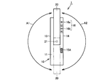
- FIG. 1 is a front view of a portable lighting device according to an embodiment of the present invention
- FIG. 2 is a rear view of the portable lighting device shown in FIG. 3 is a right side view of the portable illumination device shown in FIG. 1
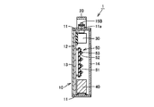
- FIG. 4 is a schematic cross-sectional view of the portable illumination device taken along line IV-IV shown in FIGS.
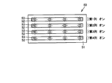
- FIG. 5 is a front view showing a configuration of an illumination unit of the portable illumination device shown in FIG.
- 1, 2, and 4 show a state in which a waterproof cap that is detachably attached to the main body of the portable lighting device is removed.
- the portable illumination device 1 includes a device main body 10 formed in a rectangular parallelepiped box shape, and a circuit that is rotatably attached to the device main body 10.
- the moving member 20 is provided.
- the apparatus body 10 is sufficiently reduced in size and weight so that it can be easily carried.
- the apparatus body 10 is preferably smaller and lighter, but from the viewpoint of performance and ease of carrying, the outer shape is approximately 25 cm to 30 cm in height, approximately 35 cm to 40 cm in width, and depth.
- the weight is about 5 cm to 10 cm, and the weight is about 1.5 kg to 3.0 kg, more preferably about 1.5 kg to 2.0 kg.
- the apparatus main body 10 includes a frame 11 that is configured in a frame shape to form an upper surface, a lower surface, a right side surface, and a left side surface of the apparatus main body 10, and a plate-like chassis 12 attached to the frame 11. .
- the frame 11 and the chassis 12 are preferably composed of relatively lightweight members having excellent weather resistance and rigidity.
- metal members such as aluminum alloy and stainless alloy, ABS (Acrylonitrile Butadiene Styrene), etc. It is comprised with the member made from resin.
- welding, screwing, or the like is preferably used.
- a solar cell panel 13 that generates power by receiving sunlight is disposed on the front surface of the apparatus body 10. More specifically, the solar cell panel 13 is fixed to the frame 11 and the chassis 12 so as to cover the front surface of the chassis 12 attached to the frame 11, and is exposed on the front surface of the apparatus main body 10. In addition, it is preferable that the exposed surface of the solar cell panel 13 is covered with translucent reinforced plastic, tempered glass, or the like from the viewpoint of preventing damage to the solar cells. Further, for fixing the solar cell panel 13 to the frame 11 and the chassis 12, sticking, bonding, fitting, screwing, or the like is preferably used.
- a cover lens 14 for making the radiation intensity of light emitted from the illumination unit 50 described later uniform is disposed on the back surface of the apparatus main body 10. More specifically, the cover lens 14 is disposed opposite to the rear surface of the chassis 12 with a distance from the rear surface of the chassis 12 attached to the frame 11 and fixed to the frame 11, and is exposed on the rear surface of the apparatus body 10. Yes.
- the cover lens 14 it is preferable from the viewpoint of weight reduction to use the injection molded product which used the translucent resin material as a raw material. For fixing the cover lens 14 to the frame 11, adhesion, fitting, screwing, or the like is preferably used.
- a control unit 30 including a control unit 31 (see FIG. 14) for overall control is disposed.
- the control unit 30 is disposed in the upper part of the space inside the apparatus main body 10 and is fixed to the back side of the chassis 12 attached to the frame 11 by, for example, screwing or the like.
- the control unit 30 includes a box-shaped case and a circuit board covered with the box-shaped case, and the above-described control unit 31 and various circuits 32 and 33 described later are provided on the circuit board. ing.
- the storage battery 40 is disposed in the lower part of the space inside the apparatus main body 10 and is fixed to the bottom of the frame 11 by, for example, screwing or the like.
- a lithium ion battery, a nickel metal hydride battery, a nickel cadmium battery, a lead battery, or the like can be used.
- the lighting unit 50 is disposed in a substantially central portion of the space inside the apparatus main body 10 and is fixed to the back side of the chassis 12 attached to the frame 11 by, for example, screwing or the like. As shown in FIG. 5, the lighting unit 50 includes a flat support plate 51, a plurality of circuit boards 52 attached to the support board 51, and a plurality of LEDs 53 mounted on the surface of the circuit board 52. Contains.
- the flat support plate 51 is disposed so as to face the back surface of the chassis 12, and thus the back surface of the support plate 51 faces the above-described cover lens 14 (see FIG. 4).
- the circuit board 52 is formed of an elongated, substantially rectangular printed wiring board, and is fixed to the back side of the support plate 51.
- Each of the plurality of circuit boards 52 is arranged in order along the longitudinal direction of the support plate 51 so that the longitudinal direction thereof matches the left-right direction of the apparatus main body 10.
- the plurality of LEDs 53 serve as the light source of the portable lighting device 1, and a plurality of LEDs 53 are arranged on the respective surfaces of the plurality of circuit boards 52 along the longitudinal direction.
- the LEDs 53 are arranged in an array on the back surface of the support plate 51, and the light emitted when the LEDs 53 emit light passes through the cover lens 14 disposed on the back surface of the apparatus main body 10. The light is emitted toward the outside of the apparatus main body 10.
- the illumination unit 50 functions as a surface light source as a whole, and the illumination range is ensured in a wide range.
- a white light emitting diode is preferably used as the LED 53.
- the LEDs 53 included in each column are connected in series, so that the plurality of LEDs 53 included in the column operate integrally, and each column is The operation is individually controllable.
- the rotating member 20 is rotatably attached to the apparatus main body 10 by a rotating connecting portion 21 including a pair of hinges. More specifically, each of the pair of rotation connecting portions 21 is located at a substantially central portion of the frame 11 constituting the left and right side surfaces of the apparatus main body 10, and in this portion, the end portion of the rotation member 20 and the frame 11 is connected and supported. As a result, the rotation axis of the rotation member 20 is arranged in parallel with the front surface of the apparatus main body 10, and the rotation member 20 is directed toward the directions of the arrows A1 and A2 as shown in FIG. It will rotate about 10 times.
- the rotation member 20 may be coupled to the frame 11 so as to be able to go around the apparatus main body 10 (that is, freely rotate without any limitation), and the rotation range thereof is It may be connected to the frame 11 so as to be partially limited (that is, limited to a rotation angle smaller than 360 degrees).
- the said rotation range is not restrict
- the rotating member 20 is configured to be held by the frame 11 of the apparatus main body 10 at a predetermined position or an arbitrary position within the rotating range (that is, the rotating member 20 is locked). Preferably it is.
- the rotating member 20 is stepped by the frame 11 of the apparatus main body 10 step by step at a predetermined position within the rotation range (that is, at a predetermined position on the orbit). It is configured to be retained.
- the rotating member 20 is preferably composed of a relatively lightweight member having excellent weather resistance and rigidity, such as a metal member such as an aluminum alloy or a stainless alloy, or a resin member such as ABS. Configured. A specific assembly structure of the rotating member 20 to the frame 11 of the apparatus main body 10 will be described later.
- an operation unit 15 ⁇ / b> A that makes it possible to switch on / off operation of the illumination unit 50, an operation state of the portable illumination device 1, and the like.
- a display unit 16 for displaying is provided.
- the operation unit 15A is configured by, for example, a push button, and the display unit 16 is configured by, for example, an LED.
- the display unit 16 includes a charge state display unit 16a for displaying whether or not the portable lighting device 1 is in a charged state, and a remaining amount display unit 16b for displaying the state of the remaining amount of the storage battery 40. It is out.
- the display part 16 is arrange
- the display unit 16 can be visually recognized.
- the external output terminal 17 may be, for example, a socket (USB terminal or the like) for charging a mobile phone, or may be a normal outlet that supplies power to the outside.
- the frame 11 of the apparatus main body 10 where the volume knob 15B is provided is provided with a cylindrical protruding portion 11a that protrudes outward from the apparatus main body 10 so as to surround the volume knob 15B. Further, the portion of the frame 11 of the apparatus main body 10 where the external output terminal 17 is provided is provided with a cylindrical protruding portion 11b that protrudes outward from the apparatus main body 10 so as to surround the external output terminal. .
- a waterproof cap (not shown) is detachably attached to the cylindrical projecting portions 11a and 11b, so that waterproofness in the portions is ensured. The specific structure of the part will be described later.
- a reflective sheet may be disposed in the space inside the apparatus main body 10.
- the reflection sheet is preferably disposed in front of the cover lens 14 and behind the chassis 12, and is disposed in a portion excluding the back side of the illumination unit 50 and excluding a portion where the illumination unit 50 is provided.
- the structure inside the main body 10 is blinded so that it cannot be seen through the cover lens 14, and the light reflected by the cover lens 14 is reflected again to irradiate the outside of the apparatus main body 10 through the cover lens 14. It is for making it happen.
- FIG. 6 is a schematic exploded view showing a structure for assembling the rotating member of the portable illumination device in the present embodiment to the device main body.
- 7A is a left side view of the apparatus main body side fixture shown in FIG. 6, and
- FIG. 7B is a right side view of the rotating member side fixture shown in FIG.
- FIG. 6 FIG. 7A and FIG. 7B, a specific assembly structure of the rotating member to the apparatus main body will be described.
- the assembly structure shown below is employed in any of the above-described pair of rotation connecting portions, only one of them will be described.
- the rotation connecting portion 21 includes a shaft portion 22 provided on the rotation member 20, an apparatus main body side attachment 23 incorporated in the frame 11, and a rotation member incorporated in the rotation member 20.
- the side fixture 24, the coil spring 25, and the bolt 26 are mainly configured.
- the shaft portion 22 is provided so as to protrude from the inner peripheral surface near the end of the rotating member 20 toward the apparatus main body 10, and a male screw portion 22a is provided at the tip thereof.
- the shaft portion 22 is a part serving as a rotation axis of the rotation member 20.
- the cross-sectional shape of the portion excluding the portion where the male screw portion 22a of the shaft portion 22 is provided (that is, the shape along the surface perpendicular to the protruding direction of the shaft portion 22) is a detent of the rotation member side mounting tool 24 described later. Any shape is possible as long as it is a shape that can be rotated (that is, the shape in which the rotating member mounting tool 24 rotates together with the shaft portion 22), for example, a substantially rectangular shape.
- the apparatus main body side fixture 23 is made of a substantially plate-like member having a substantially rectangular shape in plan view, and is made of a press-formed product formed by press-molding a metal block, for example.
- the apparatus main body side fixture 23 has a plate-like base portion 23a and a protruding portion 23b provided to protrude toward the frame 11, and is provided at the base of the protruding portion 23b on the base portion 23a side.
- the constricted portion is fitted into the frame 11 by being fitted into a support hole 11 c provided in the frame 11.
- the upper surface and the lower surface of the base portion 23a of the apparatus main body side fixture 23 are fixed by positioning ribs 11d provided on the frame 11, thereby restricting the rotation of the apparatus main body side fixture 23 relative to the frame 11. Has been.
- An insertion hole 23c penetrating the base portion 23a and the protruding portion 23b along the thickness direction is provided at a substantially central portion of the apparatus main body side fixture 23.
- the shaft portion 22 of the rotating member 20 described above is inserted through the insertion hole 23c.
- the size and the opening shape of the insertion hole 23c are set to a size and an opening shape that allow rotation of the shaft portion 22 in the insertion hole 23c.
- the center position of the insertion hole 23c is the center O2.
- a plurality of projections 23d as second engaging portions are provided along the circumferential direction of the second virtual circle C2 at positions on the circumference of the second virtual circle C2.
- Each of the plurality of protrusions 23d has a hemispherical shape, and is equidistantly spaced along the circumferential direction at a position on the circumference of the second virtual circle C2 (device main body side fixture 23 shown in the figure). In total, 12 pieces are provided every 30 °).
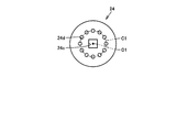
- the rotating member side fixture 24 is made of a substantially plate-like member having a substantially circular shape in plan view, and is made of, for example, a press-formed product formed by press-molding a metal plate. .
- the rotating member-side fixture 24 is a component corresponding to a latch portion, and a fitting hole 24c penetrating along the thickness direction is provided at a substantially central portion thereof.
- the opening shape of the fitting hole 24 c is, for example, similar to the cross-sectional shape of the shaft portion 22, and the size thereof is slightly larger than the size of the shaft portion 22.
- the rotating member-side fixture 24 is attached to the shaft portion 22 so as to be movable along the direction in which the shaft portion 22 extends, and the shaft portion 22 It rotates with the rotation (that is, it rotates with the shaft portion 22).
- a circle of the first virtual circle C1 having the center position O1 as the center position of the fitting hole 24c fitted to the shaft portion 22 is provided on the main surface of the rotating member side fixture 24 facing the device main body side fixture 23 .
- a plurality of holes 24d as first engaging portions are provided along the circumferential direction of the first virtual circle C1 at positions on the circumference.
- Each of the plurality of hole portions 24d has a shape penetrating along the extending direction of the shaft portion 22 (that is, along the thickness direction of the rotating member side fixture 24), and the first virtual circle C1.
- the diameter of the virtual circle C1 in which the plurality of hole portions 24d as the first engaging portion is arranged, and the diameter of the virtual circle C2 in which the plurality of protrusions 23d as the second engaging portion are arranged are of the same diameter.
- Each of the plurality of hole portions 24d as the first engaging portion has a size and a shape capable of receiving and engaging each of the plurality of protruding portions 23d as the second engaging portion.
- the coil spring 25 as an elastic biasing member has a rotating member such that one end thereof abuts on the main surface of the rotating member side fixture 24 that does not face the apparatus main body side fixture 23. It is extrapolated to 20 shaft portions 22.
- the bolt 26 is fixed to the rotating member 20 by being screwed into a male screw portion 22 a provided at the tip of the shaft portion 22 of the rotating member 20.
- the other end of the coil spring 25 comes into contact with the bolt 26, and the rotating member side fixture 24 is elastically urged by the coil spring 25 to the apparatus main body side fixture 23.
- FIG. 8 is a diagram showing a state where the rotating member is held by the apparatus main body in the portable lighting device according to the present embodiment
- FIG. 9 shows a state where the rotating member is not held by the apparatus main body.
- the plurality of holes 24 d provided in the above-described rotating member side fixture 24 and the plurality of protrusions 23 d provided in the above-described apparatus main body side fixture 23 are engaged.
- the rotating member side mounting tool 24 and the apparatus main body side mounting tool 23 are fitted on the basis of the elastic force of the coil spring 25 in the direction of the arrow B1 in the drawing, and the rotating member side mounting tool is fitted by the fitting force. 24 is locked by the apparatus main body side fixture 23.
- the rotation member 20 fixed to the rotation member side fixture 24 is restricted in its rotation and takes a holding state held by the apparatus main body 10 at the position.
- the rotation member 20 can be realized with a very simple assembly structure and a very small number of parts.
- the rotating member 20 can be attached to the apparatus main body 10 so as to be able to circulate around the apparatus main body 10 and so that the rotating member 20 is held by the apparatus main body 10 in a stepwise manner on the orbit. . Therefore, the rotating member 20 described above can be held by the apparatus main body 10 at a desired position.
- the rotating member 20 is used as a stand for supporting the apparatus main body 10 during charging as will be described later.
- it can be used as an arm for suspending the apparatus main body 10 during illumination, and can also be used as a handle for holding by hand during transportation.
- the portable illumination device 1 as in the present embodiment, it is possible to provide a portable illumination device with excellent handleability that can be used for various purposes. Therefore, its application will dramatically expand compared to conventional portable lighting devices, and it is not only used for various leisure and disasters, but also for use at construction sites and construction sites, and daily life at home. The range of use can be expected even for use.
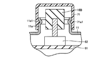
- FIG. 10 is a schematic exploded view showing a waterproof structure in a portion provided with a volume knob of the portable lighting device according to the present embodiment
- FIG. 11 shows a waterproof cap attached to the portion provided with the volume knob.
- the device main body surrounds the volume knob 15B in the frame 11 in the portion where the volume knob 15B is provided.
- a cylindrical projecting portion 11a projecting outward from 10 is provided.
- the volume knob 15B is connected to a volume switch 62, and the volume switch 62 is fixed to, for example, a circuit board 61 disposed inside the apparatus main body 10.
- the portable lighting device 1 is also intended to be used outdoors, and therefore it is necessary to employ some waterproof structure in the portion.
- a waterproof cap 71 that can be detachably attached to the cylindrical projection 11a is provided, and the waterproof cap 71 is cylindrical so as to cover the volume knob 15B.
- the waterproof structure in the said part is implement
- a bottomed cylindrical member made of resin or rubber having excellent weather resistance is preferably used.
- the annular convex portion 71a1 extending along the circumferential direction is provided on the inner peripheral surface of the waterproof cap 71, and the annular concave portion 11a1 extending along the circumferential direction is provided on the outer peripheral surface of the cylindrical protruding portion 11a, In a state where the waterproof cap 71 is attached to the cylindrical protrusion 11a, the close contact between the waterproof cap 71 and the cylindrical protrusion 11a is increased by fitting the annular protrusion 71a1 and the annular recess 11a1, Excellent waterproofness will be exhibited.
- by adopting a fitting structure using the annular convex portion 71a1 and the annular concave portion 11a1 it is possible to prevent the waterproof cap 71 from dropping off unintentionally.
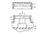
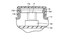
- FIG. 12 is a schematic exploded view showing a waterproof structure in a portion where the external output terminal of the portable lighting device according to the present embodiment is provided, and FIG. 13 shows a waterproof cap in the portion where the external output terminal is provided. It is a figure which shows the attached state.
- FIG. 12 and FIG. 13 the waterproof structure in the part in which the external output terminal of the portable illuminating device in this Embodiment was provided is demonstrated.
- the external output terminal 17 is surrounded by the frame 11 in the portion where the external output terminal 17 is provided.
- a cylindrical protrusion 11 b that protrudes outward from the apparatus main body 10 is provided.
- the external output terminal 17 includes a terminal receiving portion 17a that receives a connection terminal included in an external device such as a mobile phone, and a base portion 64 that supports the terminal receiving portion 17a. It is fixed to a circuit board 63 or the like disposed inside the apparatus main body 10.
- the external output terminal 17 needs to be exposed on the surface of the apparatus main body 10 so that the connection terminal included in the external device or the like can be connected.
- the portable lighting device 1 When the portable lighting device 1 is used, there is a problem that the external output terminal is short-circuited due to the influence of moisture or the like, and a problem that the external output terminal is corroded.
- the portable lighting device 1 according to the present embodiment is also intended to be used outdoors, and therefore it is necessary to employ some waterproof structure in the portion.
- a waterproof cap 72 that can be detachably attached to the cylindrical protruding portion 11 b is provided, and the waterproof cap 72 is covered with the external output terminal 17.
- the waterproof structure in the said part is implement
- a bottomed cylindrical member made of resin or rubber having excellent weather resistance is preferably used.
- the annular convex portion 72a1 extending along the circumferential direction is provided on the inner peripheral surface of the waterproof cap 72
- the annular concave portion 11b1 extending along the circumferential direction is provided on the outer peripheral surface of the cylindrical protruding portion 11b
- the close contact between the waterproof cap 72 and the cylindrical protruding portion 11b is increased by fitting the annular convex portion 72a1 and the annular concave portion 11b1.
- Excellent waterproofness will be exhibited.
- by adopting a fitting structure using the annular convex portion 72a1 and the annular concave portion 11b1 it is possible to prevent the waterproof cap 72 from unintentionally falling off.
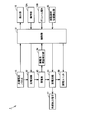
- FIG. 14 is a functional block diagram of the portable lighting device shown in FIGS. Next, with reference to this FIG. 14, the structure of the functional block of the portable illuminating device in this Embodiment is demonstrated.
- the portable lighting device 1 includes the above-described solar cell panel 13, storage battery 40, LED 53, operation unit 15A, volume knob 15B, display unit 16, external output terminal 17, and control unit.
- a charging circuit 32 In addition to 31, a charging circuit 32, a discharging circuit 33, a remaining battery level detection unit 34, and a rotating member position detection unit 35 are provided.
- the charging circuit 32 is a circuit for charging the storage battery 40 with the electric power generated by the solar cell panel 13 based on a command from the control unit 31. More specifically, the charging circuit 32 charges the storage battery 40 by sending the generated power to the storage battery 40 when the generated voltage of the solar panel 13 reaches a certain value or more. When the generated voltage becomes less than the predetermined value, charging of the storage battery 40 is stopped. In addition, the charging circuit 32 stops charging the storage battery 40 to prevent overcharging of the storage battery 40 when the storage battery 40 is fully charged, and charging the storage battery 40 when the voltage of the storage battery 40 becomes a predetermined value or less. Release the stop and resume charging.
- the charging circuit 32 is an overcurrent protection circuit that prevents the electric power sent from the solar battery panel 13 to the storage battery 40 from being in an overcurrent state, and a reverse current that prevents a reverse current flow from the storage battery 40 to the solar battery panel 13.
- a prevention circuit or the like may be included.
- the discharge circuit 33 is a circuit for supplying the electric power stored in the storage battery 40 to the illumination unit 50 and the external output terminal 17 based on a command from the control unit 31. More specifically, the discharge circuit 33 supplies power stored in the storage battery 40 to the lighting unit 50 and / or the external output terminal 17 based on a command from the control unit 31 when the voltage of the storage battery 40 is equal to or higher than a certain value. Then, when the voltage of the storage battery 40 is less than a certain value, the supply of power from the storage battery 40 to the lighting unit 50 and / or the external output terminal 17 is stopped to prevent overdischarge.
- the discharge circuit 33 may include a backflow prevention circuit that prevents a backflow of current from the external output terminal 17 to the storage battery 40.
- the storage battery remaining amount detection unit 34 detects the level of the remaining amount of power stored in the storage battery 40 by detecting the voltage of the storage battery 40, and outputs the remaining amount information to the control unit 31. It is.
- the rotation member position detection unit 35 is a part that detects the position of the rotation member 20 and outputs the position information to the control unit 31.
- a tact switch, a photoelectric sensor, a rotary encoder, an acceleration sensor, or the like arranged so that the position of the rotation member 20 can be specified can be used as the rotation member position detection unit 35.
- the operation unit 15A is a part for switching the on / off operation of the illumination unit 50 as described above. Specifically, when the user operates the operation unit 15A, this is output to the control unit 31.
- the volume knob 15B is a part for adjusting the output of the illumination unit 50 as described above. Specifically, when the user operates the volume knob 15B, the volume knob 15B is output to the control unit 31.
- the display unit 16 is a part for displaying whether or not the portable lighting device 1 is in a charged state and the remaining amount of the storage battery 40 as described above. Specifically, the portable lighting device 1 includes the portable lighting device 1. Whether or not the battery is in a charged state is displayed by turning on / off the charge state display unit 16a, and the remaining amount of the storage battery 40 is displayed by the number of lights on the remaining amount display unit 16b corresponding to the remaining amount.
- the control unit 31 is a part that controls the entire portable lighting device 1 as described above, information on the generated voltage from the solar cell panel 13, information on the remaining amount from the remaining battery level detection unit 34, and a rotating member. Based on the input of position information from the position detection unit 35, information on presence / absence of user operation from the operation unit 15A and the volume knob 15B, etc., the charging circuit 32, the discharge circuit 33, the illumination unit 50, and the display unit 16 are received. Control of the operation.
- the control unit 31 controls the operation of the functional blocks represented by the solar cell panel 13 and the lighting unit 50 based on the position information of the rotating member 20. .
- FIG. 15 is a schematic diagram for explaining how the portable lighting device according to the present embodiment operates in accordance with the position of the rotating member.
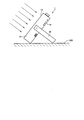
- FIG. 16 is a diagram illustrating a charged state of the portable lighting device according to the present embodiment.
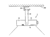
- FIG. 17A is a diagram illustrating a usage state when the portable lighting device according to the present embodiment is suspended from a ceiling
- FIG. 17B is a diagram illustrating an operating state of the lighting unit in the usage state illustrated in FIG. 17A.
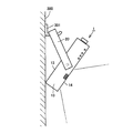
- FIG. 18A is a diagram illustrating a usage state when the portable illumination device according to the present embodiment is used while being hung on a wall surface
- FIG. 18B is a diagram illustrating an operation state of the illumination unit in the usage state illustrated in FIG. 18A. is there.
- FIG. 18A is a diagram illustrating a usage state when the portable illumination device according to the present embodiment is used while being hung on a wall surface
- FIG. 18B is a diagram illustrating an operation state of the illumination unit in the usage state illustrated in FIG.
- FIG. 19A is a diagram illustrating another usage state when the portable lighting device according to the embodiment of the present invention is used while being hung on a wall surface
- FIG. 19B is an operation state of the lighting unit in the usage state illustrated in FIG. 19A
- FIG. FIG. 20A is a diagram illustrating still another usage state when the portable lighting device according to the embodiment of the present invention is used on a wall surface
- FIG. 20B is an operation of the lighting unit in the usage state illustrated in FIG. 20A. It is a figure which shows a state.
- FIG. 15 the relationship between the position of the rotating member and the operation of each functional block will be described, and with reference to FIG. 16 to FIG. 20B, charging of the portable illumination device in the present embodiment will be described.
- the state and use state will be described.
- the rotation position of the rotation member 20 is set to the reference position when the rotation member 20 is at a position facing the upper surface of the apparatus body 10.
- the rotating member 20 is configured to be able to take at least eight positions including the reference position.
- the rotating member 20 is 30 within the rotatable range. It can be held by the apparatus main body 10 step by step at a total of 12 positions per degree, and the eight positions are included in the 12 positions.
- the reference position where the angle of the rotation member 20 is 0 ° is a fixed position for transportation that the rotation member 20 should take when the portable lighting device 1 is transported.
- the turning member 20 serves as a handle for the hand to hold.
- the control unit 31 controls the operation of the discharge circuit 33 and the illumination unit 50 to turn off the LED 53 and turn off the illumination.
- the control unit 31 may control the operation of the charging circuit 32 so that the power generated by the solar cell panel 13 is charged in the storage battery 40, or the charging is not performed. It may be. However, even when charging is performed, the charging operation is not performed when the generated voltage of the solar cell panel 13 is equal to or lower than a predetermined value or when the storage battery 40 is fully charged.
- the position where the angle of the rotating member 20 is ⁇ 90 ° is a fixed position for charging in which the solar battery panel 13 receives sunlight and performs the charging operation of the storage battery 40.
- the rotating member 20 serves as a stand for supporting the apparatus main body 10 as shown in FIG. That is, in this state, since the rotating member 20 is at a position facing the back surface of the apparatus main body 10, the portable illumination is performed so that the rotating member 20 contacts the floor surface 100 (may be the ground surface).
- the solar cell panel 13 is inclined and faces in a direction suitable for receiving sunlight.
- the control unit 31 controls the operation of the discharge circuit 33 and the illumination unit 50 to turn off the LED 53 and turn off the illumination.
- the storage battery 40 is charged with the electric power generated by the solar battery panel 13 by controlling the operation of the charging circuit 32. Further, at that time, the control unit 31 notifies the user that the charging operation is being performed by turning on the charging state display unit 16a of the display unit 16. Even when the rotating member 20 is in the fixed position for charging, the charging operation is performed when the power generation voltage of the solar battery panel 13 is equal to or lower than a predetermined value or when the storage battery 40 is fully charged. Does not.
- the position where the angle of the rotating member 20 is + 90 ° is a fixed position for hanging from the ceiling when the portable lighting device 1 is hung from the ceiling and used as lighting.
- the rotating member 20 becomes an arm that is hooked on a locking tool 201 provided on the ceiling 200 as shown in FIG. 17A.
- the rotating member 20 is in a position facing the front surface of the apparatus main body 10, so that the rear surface of the apparatus main body 10 faces vertically downward by hooking the rotating member 20 on the locking tool 201. become.
- the control unit 31 controls the operation of the discharge circuit 33 and the illumination unit 50 to turn on the LED 53 and turn on the illumination. .
- the back surface of the apparatus main body 10 is directed vertically downward.
- illumination is performed at 100% output by turning on all the LEDs 53 in the first to fourth columns.
- the control unit 31 controls the operation of the charging circuit 32 so that charging is not performed.
- the position where the angle of the rotation member 20 is + 30 ° is the first fixed position for wall hanging when the portable lighting device 1 is used as lighting by hanging on the wall surface.
- the turning member 20 becomes an arm that is hooked on the locking tool 301 provided on the wall surface 300 as shown in FIG.
- the rotating member 20 is located at a position facing the upper portion near the upper end of the front surface of the apparatus main body 10. Will face slightly below the horizontal direction.
- the control unit 31 controls the operation of the discharge circuit 33 and the illumination unit 50 to turn on the LED 53 and turn on the illumination.
- the back surface of the apparatus main body 10 faces slightly downward from the horizontal direction.
- the LEDs 53 in the first row are turned off and only the LEDs 53 in the second to fourth rows are turned on to perform illumination with 75% output.
- the control unit 31 controls the operation of the charging circuit 32 so that charging is not performed.
- the position where the angle of the rotation member 20 is + 60 ° is the second fixed position for wall hanging when the portable lighting device 1 is used as lighting by hanging on the wall surface.
- the rotating member 20 becomes an arm that is hooked on a locking tool 301 provided on the wall surface 300 as shown in FIG.
- the rotating member 20 since the rotating member 20 is at a position facing the upper portion near the center of the front surface of the apparatus main body 10, the rear surface of the apparatus main body 10 is obtained by hooking the rotating member 20 on the locking tool 301. Will face down more than the horizontal direction.
- the control unit 31 controls the operation of the discharge circuit 33 and the illumination unit 50 to turn on the LED 53 and turn on the illumination. .
- the back surface of the apparatus main body 10 faces downward from the horizontal direction.
- the rotating member 20 is further unnecessary as compared with the case where the rotating member 20 is in the first fixed position for wall hanging.
- the LEDs 53 in the first row and the second row are turned off, and the LEDs 53 in the third row and the fourth row are turned off. Illumination with 50% output is performed by turning on only.
- the control unit 31 controls the operation of the charging circuit 32 so that charging is not performed.
- the position where the angle of the rotating member 20 is + 180 ° is the third fixed position for hanging on the wall when the portable lighting device 1 is used as lighting by hanging on the wall.
- the turning member 20 becomes an arm that is hooked on the locking tool 301 provided on the wall surface 300 as shown in FIG. That is, in this state, since the rotating member 20 is located at a position facing the lower surface of the apparatus main body 10, the rear surface of the apparatus main body 10 faces the horizontal direction by hooking the rotating member 20 on the locking tool 301. become.
- the control unit 31 controls the operation of the discharge circuit 33 and the illumination unit 50 to turn on the LED 53 and turn on the illumination. .
- the back surface of the apparatus main body 10 is directed in the horizontal direction.
- illumination is performed at 100% output by turning on all the LEDs 53 in the first to fourth columns.
- the control unit 31 controls the operation of the charging circuit 32 so that charging is not performed.
- the position where the angle of the rotation member 20 is + 150 ° is the fourth fixed position for wall hanging when the portable lighting device 1 is used as lighting by hanging on the wall surface.
- the rotation member 20 becomes an arm that is hooked on a locking tool provided on the wall surface.
- the top and bottom are only reversed from the case where the rotation member 20 is in the above-mentioned wall-hanging first fixing position, and therefore detailed description thereof will be given.
- the LEDs 53 in the first to third rows are turned on, and the LEDs 53 in the fourth row are turned off.
- the position where the angle of the rotation member 20 is + 120 ° is the fifth fixed position for wall hanging when the portable lighting device 1 is used as lighting by hanging on the wall surface.
- the turning member 20 When the turning member 20 is positioned at the fifth fixed position for hanging on the wall, the turning member 20 becomes an arm that is hooked on a locking tool provided on the wall surface.
- the rotating member 20 when the rotating member 20 is in the fifth fixed position for wall hanging, only the top and bottom are reversed from the case where the rotating member 20 is in the second fixed position for wall hanging as described above. In this case, the LEDs 53 in the first row and the second row are turned on, and the LEDs 53 in the third row and the fourth row are turned off.
- the operation unit 15 ⁇ / b> A that makes it possible to switch the on / off operation of the lighting unit 50 and the output of the lighting unit 50 are adjusted.
- a volume knob 15B is provided to enable it.
- the operation unit 15A and the volume knob 15B can switch on / off operation and output of the illumination unit 50 regardless of the position of the rotating member 20 described above.
- the operation unit 15A and the volume knob 15B are operated by the operation unit 15A and the volume knob 15B.
- the control unit 31 performs control according to the user's command in preference to the operation of the control unit 31 described above.
- the operation of the illumination unit 50 and the like included in the portable illumination device 1 is controlled according to the position of the rotating member 20. Therefore, by operating the rotating member 20, the mode is automatically switched according to the usage mode, so that the portable lighting device can be easily handled. Therefore, its application will dramatically expand compared to conventional portable lighting devices, and it is not only used for various leisure and disasters, but also for use at construction sites and construction sites, and daily life at home. The range of use can be expected even for use.
- the illumination output is automatically adjusted to save energy.
- the portable lighting device 1 since the electric power generated by the solar panel 13 is used as the power source of the lighting unit 50, the power can be made more efficient by adopting the above configuration. By using it frequently, it is possible to prevent the occurrence of a situation where power is insufficient during use and the use cannot be performed or a situation where it is necessary to frequently charge the battery.
- the LED may be configured to emit light by PWM (Pulse Width Modulation) control, and the illuminance may be adjusted by adjusting the duty ratio as necessary.
- PWM Pulse Width Modulation
- the case where the illuminance of the LED is adjusted according to the position of the rotating member is exemplified, but it is not always necessary to configure in this way, and the rotating member is simply used. Depending on the position, all the LEDs may be turned on / off.
- the charging operation is not performed when the LED is turned on.
- the charging operation is also performed when the LED is turned on. May be configured to be performed.
- the position of the rotating member is fixed in stages, but the position of the rotating member may be fixed at an arbitrary position.
- the rotatable range of the rotating member is divided for each predetermined angle, and when the rotating member is located within the divided range, the lighting unit or the like performs an operation according to the range. You may comprise.
- the relationship between the position of the rotating member and the operation of the lighting unit and the like shown in the above-described embodiment is merely an example when the present invention is applied.
- the shape of the apparatus main body, the shape of the rotating member, and the apparatus The position can be appropriately changed according to the mounting position of the rotating member with respect to the main body, the configuration of the lighting unit, and the like.
- the 1st engaging part provided in the rotation member side attaching tool as a latch part was comprised by the hole part penetrated along the direction where the shaft part of a rotation member extends.
- the first engagement portion may be configured by a recess that is recessed along the direction in which the shaft portion of the rotating member extends.
- the second engaging portion provided in the apparatus main body side fixture is configured by a hemispherical protrusion. Is not limited to this, and can be changed as appropriate.
- the 1st engaging part provided in a rotation member side fixture is comprised in the hole part penetrated along the direction where the shaft part of a rotation member extends, and the apparatus main body side
- the second engaging portion provided in the fixture is configured by the protrusion
- the first engaging portion provided in the rotating member side fixture is configured by the protruding portion
- the second engagement portion provided on the apparatus main body side fixture by a recess or a hole.
- both the 1st engaging part provided in a rotation member side fixture and the 2nd engaging part provided in an apparatus main body side fixture are provided in multiple numbers is illustrated.
- the number may be singular, and the number can be changed as appropriate based on the number and angle of the positions at which the rotating member is held with respect to the apparatus main body.
- the case where the apparatus main body side fixture is fixed to the frame of the apparatus main body is illustrated, but the apparatus main body side fixture is not provided, and the apparatus main body side fixture is directly attached to the frame of the apparatus main body.
- a configuration in which the second engaging portion is provided is also possible.
- the rotating member side fixture and the apparatus main body side fixture are both made of a metal member as in the present embodiment described above, the durability is difficult to break even when used for a long period of time. It can be excellent.
- the rotating member side fixture (that is, the latch portion) and the apparatus main body side fixture that is, the portion of the apparatus main body that engages with the latch portion
- the apparatus main body is configured to have a rectangular parallelepiped box-like outer shape is illustrated, but it is naturally possible to have other shapes.
Landscapes
- Engineering & Computer Science (AREA)
- General Engineering & Computer Science (AREA)
- Life Sciences & Earth Sciences (AREA)
- Sustainable Development (AREA)
- Non-Portable Lighting Devices Or Systems Thereof (AREA)
Abstract
Description
Claims (21)
- 正面および背面を有する装置本体(10)と、
前記装置本体(10)の前記正面に配置された太陽電池パネル(13)と、
前記装置本体(10)に設けられ、前記太陽電池パネル(13)で発電された電力を蓄電する蓄電池(40)と、
前記装置本体(10)に設けられ、前記蓄電池(40)から電力が供給されることで発光し、前記装置本体(10)の前記背面から前記装置本体(10)の外部に向けて光を照射する照明ユニット(50)と、
前記装置本体(10)に回動自在に取付けられ、充電時において前記装置本体(10)を支持するためのスタンドとなり得、照明時において前記装置本体(10)を吊り下げるためのアームとなり得る回動部材(20)とを備えた、可搬型照明装置。 - 前記回動部材(20)の位置を検出する位置検出部(35)と、
前記位置検出部(35)にて検出された回動部材の位置情報に基づいて前記照明ユニット(50)の動作を制御する制御部(31)とをさらに備えた、請求の範囲第1項に記載の可搬型照明装置。 - 前記装置本体(10)は、箱状の形状を有し、
前記回動部材(20)が、前記装置本体(10)の相対する側面に取付けられることで前記装置本体(10)回りに回動する、請求の範囲第2項に記載の可搬型照明装置。 - 前記制御部(31)は、前記回動部材(20)が前記装置本体(10)の前記正面側に位置する場合において前記蓄電池(40)から前記照明ユニット(50)に電力が供給されるように制御し、これにより前記照明ユニット(50)を作動させ、前記回動部材(20)が前記装置本体(10)の前記背面側に位置する場合において前記蓄電池(40)から前記照明ユニット(50)に電力が供給されないように制御し、これにより前記照明ユニット(50)の作動を停止させる、請求の範囲第2項に記載の可搬型照明装置。
- 前記制御部(31)は、前記回動部材(20)が前記装置本体(10)の前記正面側に位置する場合において前記蓄電池(40)から前記照明ユニット(50)に供給される電力量を前記回動部材(20)の位置に応じて可変に制御し、これにより前記照明ユニット(50)の照度を前記回動部材(20)の位置に応じて可変に調節する、請求の範囲第2項に記載の可搬型照明装置。
- 前記照明ユニット(50)の動作を前記回動部材(20)の位置によらずに切り替えることを可能にする操作部(15A)をさらに備えた、請求の範囲第2項に記載の可搬型照明装置。
- 前記制御部(31)は、前記回動部材(20)が前記装置本体(10)の前記背面側に位置する場合において前記太陽電池パネル(13)にて発電された電力を前記蓄電池(40)に充電する動作を制御し、前記回動部材(20)が前記装置本体(10)の前記正面側に位置する場合において前記太陽電池パネル(13)にて発電された電力を前記蓄電池(40)に充電しないように制御する、請求の範囲第2項に記載の可搬型照明装置。
- 前記回動部材(20)が、前記装置本体(10)の周囲を周回可能となるように前記装置本体(10)に取付けられている、請求の範囲第1項に記載の可搬型照明装置。
- 前記回動部材が、前記装置本体の周囲を回動する周回軌道上の所定位置において、前記装置本体によって保持可能とされている、請求の範囲第8項に記載の可搬型照明装置。
- 前記回動部材(20)は、当該回動部材(20)の回動軸となるシャフト部(22)と、前記シャフト部(22)の延びる方向に沿って移動可能に前記シャフト部(22)に取付けられ、前記シャフト部(22)の回転に伴って回転するラッチ部(24)と、前記ラッチ部(24)を前記装置本体(10)に向けて弾性付勢する弾性付勢部材(25)とを含み、
前記装置本体(10)には、前記シャフト部(22)が挿通する挿通孔(23c)が設けられ、
前記ラッチ部(24)の前記装置本体(10)に対面する部分には、第1係合部(24d)が設けられ、
前記装置本体(10)の前記ラッチ部(24)に対面する部分には、前記第1係合部(24d)に係合可能な第2係合部(23d)が設けられ、
前記弾性付勢部材(25)の弾性力に基づいて前記第1係合部(24d)が前記第2係合部(23d)に係合することで前記回動部材(20)が前記装置本体(10)によって保持された保持状態と、前記弾性付勢部材(25)の弾性力に抗して前記第1係合部(24d)が前記第2係合部(23d)に非係合となることで前記回動部材(20)が前記装置本体(10)によって保持されない非保持状態とを採ることにより、前記回動部材(20)が、前記装置本体(10)の周囲を回動する周回軌道上の所定位置において、前記装置本体(10)によって保持可能とされている、請求の範囲第9項に記載の可搬型照明装置。 - 前記第1係合部(24d)が、前記ラッチ部(24)の前記装置本体(10)に対面する部分の、前記シャフト部(22)を中心とする第1仮想円(C1)の円周上の位置に、当該第1仮想円(C1)の周方向に沿って等間隔に複数設けられ、
前記第2係合部(23d)が、前記装置本体(10)の前記ラッチ部(24)に対面する部分の、前記挿通孔(23c)を中心とする、前記第1仮想円(C1)と同一直径の第2仮想円(C2)の円周上の位置に、当該第2仮想円(C2)の周方向に沿って等間隔に前記第1係合部(24d)と同数設けられ、
これにより、前記回動部材(20)が、前記装置本体(10)の周囲を回動する周回軌道上において、段階的に前記装置本体(10)によって保持可能とされている、請求の範囲第10項に記載の可搬型照明装置。 - 前記弾性付勢部材(25)が、前記シャフト部(22)に外挿されたコイルバネにて構成され、
前記第1係合部(24d)および前記第2係合部(23d)の一方が、前記シャフト部(22)の延びる方向に沿って突出した半球状の突起部にて構成され、
前記第1係合部(24d)および前記第2係合部(23d)の他方が、前記シャフト部(22)の延びる方向に沿って窪む凹部または前記シャフト部(22)が延びる方向に沿って貫通する孔部にて構成されている、請求の範囲第10項に記載の可搬型照明装置。 - 前記ラッチ部(24)が、金属製の部材にて構成され、
前記装置本体(10)の前記挿通孔(23c)および前記第2係合部(24d)が設けられた部分が、金属製の部材にて構成されている、請求の範囲第10項に記載の可搬型照明装置。 - 充電状態にあるか否かを表示するための充電状態表示部(16a)が、前記装置本体(10)の前記正面および前記背面を除く部分の外表面に設けられている、請求の範囲第1項に記載の可搬型照明装置。
- 前記蓄電池の残量の状態を表示するための残量表示部(16b)が、前記装置本体(10)の前記正面および前記背面を除く部分の外表面に設けられている、請求の範囲第1項に記載の可搬型照明装置。
- 前記照明ユニット(50)の出力を調節するためのボリューム摘み(15B)をさらに備えた、請求の範囲第1項に記載の可搬型照明装置。
- 前記ボリューム摘み(15B)が設けられた部分の前記装置本体(10)に、防水キャップ(71)が取付け可能とされている、請求の範囲第16項に記載の可搬型照明装置。
- 前記蓄電池(40)に蓄電された電力を外部へ出力することを可能にする外部出力端子(17)をさらに備えた、請求の範囲第1項に記載の可搬型照明装置。
- 前記外部出力端子(17)が設けられた部分の前記装置本体(10)に、防水キャップ(72)が取付け可能とされている、請求の範囲第18項に記載の可搬型照明装置。
- 前記照明ユニット(50)に含まれる光源(53)が、LEDである、請求の範囲第1項に記載の可搬型照明装置。
- 前記回動部材(20)は、運搬時において手で持つための把手となり得る、請求の範囲第1項に記載の可搬型照明装置。
Priority Applications (1)
| Application Number | Priority Date | Filing Date | Title |
|---|---|---|---|
| CN201080038140.8A CN102483194B (zh) | 2009-08-28 | 2010-08-10 | 移动式照明装置 |
Applications Claiming Priority (4)
| Application Number | Priority Date | Filing Date | Title |
|---|---|---|---|
| JP2009198376A JP5187855B2 (ja) | 2009-08-28 | 2009-08-28 | 可搬型照明装置 |
| JP2009-198376 | 2009-08-28 | ||
| JP2010064066A JP2011198613A (ja) | 2010-03-19 | 2010-03-19 | 可搬型照明装置 |
| JP2010-064066 | 2010-03-19 |
Publications (1)
| Publication Number | Publication Date |
|---|---|
| WO2011024643A1 true WO2011024643A1 (ja) | 2011-03-03 |
Family
ID=43627749
Family Applications (1)
| Application Number | Title | Priority Date | Filing Date |
|---|---|---|---|
| PCT/JP2010/063552 Ceased WO2011024643A1 (ja) | 2009-08-28 | 2010-08-10 | 可搬型照明装置 |
Country Status (2)
| Country | Link |
|---|---|
| CN (1) | CN102483194B (ja) |
| WO (1) | WO2011024643A1 (ja) |
Cited By (4)
| Publication number | Priority date | Publication date | Assignee | Title |
|---|---|---|---|---|
| WO2013080836A1 (ja) * | 2011-11-30 | 2013-06-06 | パナソニック株式会社 | 発光装置 |
| JP2015046276A (ja) * | 2013-08-28 | 2015-03-12 | 株式会社エム・エイチ・シー | 携帯用ライト |
| USD883544S1 (en) | 2018-03-19 | 2020-05-05 | Milwaukee Electric Tool Corporation | Light |
| US10935223B2 (en) | 2018-03-19 | 2021-03-02 | Milwaukee Electric Tool Corporation | Folding flood lighting device |
Citations (6)
| Publication number | Priority date | Publication date | Assignee | Title |
|---|---|---|---|---|
| JPH04135101U (ja) * | 1991-06-03 | 1992-12-16 | 真人 中村 | 太陽電池を利用した懐中電灯 |
| JP2002237201A (ja) * | 2001-02-13 | 2002-08-23 | Uingu:Kk | 風呂用浮遊ライト |
| JP3103994U (ja) * | 2004-03-12 | 2004-08-26 | 有限会社 アーマライト | 携帯型マルチソーラーled照明及び電源装置 |
| JP3107488U (ja) * | 2004-08-31 | 2005-02-03 | 游木溢 | マルチ用途歯ブラシ殺菌洗浄器 |
| JP2008129166A (ja) * | 2006-11-17 | 2008-06-05 | Advanced Cable Systems Corp | 光ファイバ配線系およびスプリッタボックス |
| JP2008253789A (ja) * | 2008-04-30 | 2008-10-23 | Olympus Corp | 撮像装置 |
-
2010
- 2010-08-10 CN CN201080038140.8A patent/CN102483194B/zh not_active Expired - Fee Related
- 2010-08-10 WO PCT/JP2010/063552 patent/WO2011024643A1/ja not_active Ceased
Patent Citations (6)
| Publication number | Priority date | Publication date | Assignee | Title |
|---|---|---|---|---|
| JPH04135101U (ja) * | 1991-06-03 | 1992-12-16 | 真人 中村 | 太陽電池を利用した懐中電灯 |
| JP2002237201A (ja) * | 2001-02-13 | 2002-08-23 | Uingu:Kk | 風呂用浮遊ライト |
| JP3103994U (ja) * | 2004-03-12 | 2004-08-26 | 有限会社 アーマライト | 携帯型マルチソーラーled照明及び電源装置 |
| JP3107488U (ja) * | 2004-08-31 | 2005-02-03 | 游木溢 | マルチ用途歯ブラシ殺菌洗浄器 |
| JP2008129166A (ja) * | 2006-11-17 | 2008-06-05 | Advanced Cable Systems Corp | 光ファイバ配線系およびスプリッタボックス |
| JP2008253789A (ja) * | 2008-04-30 | 2008-10-23 | Olympus Corp | 撮像装置 |
Cited By (4)
| Publication number | Priority date | Publication date | Assignee | Title |
|---|---|---|---|---|
| WO2013080836A1 (ja) * | 2011-11-30 | 2013-06-06 | パナソニック株式会社 | 発光装置 |
| JP2015046276A (ja) * | 2013-08-28 | 2015-03-12 | 株式会社エム・エイチ・シー | 携帯用ライト |
| USD883544S1 (en) | 2018-03-19 | 2020-05-05 | Milwaukee Electric Tool Corporation | Light |
| US10935223B2 (en) | 2018-03-19 | 2021-03-02 | Milwaukee Electric Tool Corporation | Folding flood lighting device |
Also Published As
| Publication number | Publication date |
|---|---|
| CN102483194B (zh) | 2014-02-12 |
| CN102483194A (zh) | 2012-05-30 |
Similar Documents
| Publication | Publication Date | Title |
|---|---|---|
| US7897277B2 (en) | Reversible battery cartridge | |
| US8083392B2 (en) | LED light has removable self-power LED unit(s) | |
| US11353185B2 (en) | Electric lighting system and components, and charging and connection mechanisms thereof | |
| US20100039792A1 (en) | Battery Powered Lighting Appliance | |
| CA2717059A1 (en) | Lantern with removable lights | |
| US10591810B2 (en) | LED projection light has multiple functions | |
| JP5187855B2 (ja) | 可搬型照明装置 | |
| WO2011024643A1 (ja) | 可搬型照明装置 | |
| KR100987460B1 (ko) | 랜턴 겸용 전기스탠드 | |
| US20150055330A1 (en) | Solar Lantern Lamp having LED Candel | |
| JP2011198613A (ja) | 可搬型照明装置 | |
| AU2011209798A1 (en) | Folding spotlight | |
| WO2011010326A2 (en) | A portable lighting device | |
| KR200482202Y1 (ko) | 스탠드형 조명 또는 걸이형 조명 또는 휴대용 조명으로 겸용할 수 있는 다용도 조명 장치 | |
| JP3113977U (ja) | 携帯用の多用途光電子探照灯 | |
| JP3176527U (ja) | Led電球 | |
| JP2014074294A (ja) | 照明具 | |
| JP2012028129A (ja) | 携帯電灯 | |
| JP2013048016A (ja) | 可搬型照明具 | |
| CN210637930U (zh) | 照明装置 | |
| CN107676719B (zh) | 子母灯装置及灯具 | |
| CN108591930A (zh) | 应急充电照明灯 | |
| US12601454B1 (en) | Solar-powered waterproof decorative lamp | |
| CN217519697U (zh) | 多功能便携灯具 | |
| CN110207057A (zh) | 便携式户外灯具 |
Legal Events
| Date | Code | Title | Description |
|---|---|---|---|
| WWE | Wipo information: entry into national phase |
Ref document number: 201080038140.8 Country of ref document: CN |
|
| 121 | Ep: the epo has been informed by wipo that ep was designated in this application |
Ref document number: 10811693 Country of ref document: EP Kind code of ref document: A1 |
|
| NENP | Non-entry into the national phase |
Ref country code: DE |
|
| WWE | Wipo information: entry into national phase |
Ref document number: 2549/CHENP/2012 Country of ref document: IN |
|
| 122 | Ep: pct application non-entry in european phase |
Ref document number: 10811693 Country of ref document: EP Kind code of ref document: A1 |