WO2011024372A1 - 接触圧測定方法 - Google Patents
接触圧測定方法 Download PDFInfo
- Publication number
- WO2011024372A1 WO2011024372A1 PCT/JP2010/004435 JP2010004435W WO2011024372A1 WO 2011024372 A1 WO2011024372 A1 WO 2011024372A1 JP 2010004435 W JP2010004435 W JP 2010004435W WO 2011024372 A1 WO2011024372 A1 WO 2011024372A1
- Authority
- WO
- WIPO (PCT)
- Prior art keywords
- contact pressure
- sensor
- sensor element
- button
- memory
- Prior art date
- Legal status (The legal status is an assumption and is not a legal conclusion. Google has not performed a legal analysis and makes no representation as to the accuracy of the status listed.)
- Ceased
Links
Images



Classifications
-
- A—HUMAN NECESSITIES
- A61—MEDICAL OR VETERINARY SCIENCE; HYGIENE
- A61B—DIAGNOSIS; SURGERY; IDENTIFICATION
- A61B5/00—Measuring for diagnostic purposes; Identification of persons
- A61B5/103—Measuring devices for testing the shape, pattern, colour, size or movement of the body or parts thereof, for diagnostic purposes
-
- A—HUMAN NECESSITIES
- A61—MEDICAL OR VETERINARY SCIENCE; HYGIENE
- A61B—DIAGNOSIS; SURGERY; IDENTIFICATION
- A61B5/00—Measuring for diagnostic purposes; Identification of persons
- A61B5/44—Detecting, measuring or recording for evaluating the integumentary system, e.g. skin, hair or nails
- A61B5/441—Skin evaluation, e.g. for skin disorder diagnosis
- A61B5/447—Skin evaluation, e.g. for skin disorder diagnosis specially adapted for aiding the prevention of ulcer or pressure sore development, i.e. before the ulcer or sore has developed
-
- A—HUMAN NECESSITIES
- A61—MEDICAL OR VETERINARY SCIENCE; HYGIENE
- A61B—DIAGNOSIS; SURGERY; IDENTIFICATION
- A61B5/00—Measuring for diagnostic purposes; Identification of persons
- A61B5/68—Arrangements of detecting, measuring or recording means, e.g. sensors, in relation to patient
- A61B5/6887—Arrangements of detecting, measuring or recording means, e.g. sensors, in relation to patient mounted on external non-worn devices, e.g. non-medical devices
- A61B5/6892—Mats
-
- A—HUMAN NECESSITIES
- A61—MEDICAL OR VETERINARY SCIENCE; HYGIENE
- A61B—DIAGNOSIS; SURGERY; IDENTIFICATION
- A61B5/00—Measuring for diagnostic purposes; Identification of persons
- A61B5/74—Details of notification to user or communication with user or patient; User input means
- A61B5/7475—User input or interface means, e.g. keyboard, pointing device, joystick
-
- A—HUMAN NECESSITIES
- A61—MEDICAL OR VETERINARY SCIENCE; HYGIENE
- A61B—DIAGNOSIS; SURGERY; IDENTIFICATION
- A61B2562/00—Details of sensors; Constructional details of sensor housings or probes; Accessories for sensors
- A61B2562/02—Details of sensors specially adapted for in-vivo measurements
- A61B2562/0247—Pressure sensors
-
- A—HUMAN NECESSITIES
- A61—MEDICAL OR VETERINARY SCIENCE; HYGIENE
- A61B—DIAGNOSIS; SURGERY; IDENTIFICATION
- A61B2562/00—Details of sensors; Constructional details of sensor housings or probes; Accessories for sensors
- A61B2562/16—Details of sensor housings or probes; Details of structural supports for sensors
- A61B2562/168—Fluid filled sensor housings
Definitions
- the present invention for example, can easily measure the contact pressure between each part of the body of a patient such as a patient sleeping on a bed and the bedding, and further save the measurement result in a memory or make it easy to visually recognize the measurement result.
- the present invention relates to a contact pressure measuring method.
- Patent Document 1 a contact pressure measuring device for measuring a contact pressure generated between a patient's body surface and a bedding with a simple structure as shown in Patent Document 1 has been proposed.
- This contact pressure measuring device sandwiches the foamed plastic that returns to its original shape when the pressure is released between two air-impermeable sheets without pressing, and the air-impermeable from the vicinity of the foamed plastic.
- a tube extending to the outside of the sheet, and a contact pressure sensor configured by adhering the foamed plastic and the air-impermeable sheet around the tube to each other; and a tip portion of the tube of the contact pressure sensor.
- the pressure detector arranged in the position and the pressure signal of the pressure detector are output as they are when the signal from the pressure detector is single, and the average value or maximum value of these signal values in the case of multiple signals
- a display unit that digitally displays an output signal of the conversion circuit.
- Patent Document 1 when measuring the contact pressure, the device is turned on with the contact pressure sensor sandwiched between the patient and the bedding, and the display unit is contacted with the contact pressure sensor. It can be seen that the contact pressure measurement method of displaying the pressure is used.
- the present invention has been made in view of the above-described problems, and can measure the contact pressure between a patient and bedding with high accuracy based on the positional relationship, and further store the measurement result in a memory, or visually To provide a contact pressure measurement method that makes it easier to recognize
- the method for measuring contact pressure according to claim 1 is characterized in that one sensor element that applies air pressure to the outside through a tube connected when air is sealed inside and pressed is provided in a central portion and a plurality of concentric circles around the sensor element.
- the main body has a power switch, a start button for normal mode, a guidance button for guidance mode, a memory button, a memory, and a liquid crystal display.
- an external schematic diagram of the contact pressure sensor is displayed on the liquid crystal display, and when the contact pressure is applied to the contact pressure sensor, each of the above-described external schematic diagrams
- a contact pressure measuring method of a contact pressure measuring device configured to display each contact pressure in accordance with an arrangement state of sensor elements, and measuring the contact pressure
- the contact pressure sensor is sandwiched between a measurement part and an object with which the measurement part comes into contact, and after the power switch is turned on, the guidance button is turned on, and the liquid crystal display is shown in the schematic external view.
- the contact pressure to each sensor element is displayed at a display position corresponding to the arrangement state of each sensor element, and then the sensor element showing the highest contact pressure is positioned at the center of the schematic external view.
- the contact pressure measuring method after measuring the contact pressure to the sensor element and subsequently determining the maximum value of the contact pressure to the sensor element, the memory button Is turned on, the numerical value is stored in the memory, and then the start button is turned on to measure the contact pressure.
- the contact pressure of each sensor element of the contact pressure sensor is sequentially measured at predetermined intervals by pressing and holding the start button to turn it on.
- the measurement result is displayed on the liquid crystal display as a graph and a numerical value so that the temporal change of the contact pressure to each sensor element can be recognized.
- the contact pressure sensor when measuring the contact pressure, the contact pressure sensor is first sandwiched between the measurement site and the object that the measurement site contacts, and the guidance button is turned on after the power is turned on.
- the contact pressure to each sensor element is displayed at a display position corresponding to the arrangement state of each sensor element on the liquid crystal display, so that the sensor element showing the highest contact pressure becomes the sensor element located at the center of the contact pressure sensor
- the contact pressure sensor can be moved. Then, it is possible to easily measure the value at which the contact pressure is maximized by turning on the start button.
- the start button is turned on, the contact pressure is measured, the maximum value of the contact pressure is determined, and then the memory switch is turned on to store the numerical value in the memory.
- the contact pressure is continuously measured, so that the storage in the memory and the measurement of the contact pressure can be performed alternately.
- the contact pressure to each sensor element preserve
- the guidance button is turned on to enter the guidance mode, and the start button is further pressed for a long time so that the contact pressure of each sensor element of the contact pressure sensor is set at a predetermined interval.
- FIG. 1 It is an external view which shows embodiment which concerns on this invention and shows the state which connected the contact pressure sensor to the main body.
- A is explanatory drawing of the place which connects a contact pressure sensor (not shown) to a main body via a coupler
- (b) is a figure which shows the state which locked the coupler with the locking mechanism with respect to the main body.
- the coupler mechanism which consists of the coupler convex part connected with the coupler concave part provided in the main body and a contact pressure sensor is shown, (a) shows before the coupling
- It is a block diagram which shows the electric circuit of a main body. It is a flowchart when measuring a contact pressure. In the guidance mode, the contact pressure to each sensor element shown on the main unit liquid crystal display is illustrated, and the contact pressure to each sensor element changes as indicated by the arrow by moving the contact pressure sensor FIG.
- FIG. 1 shows a contact pressure measuring device for carrying out the contact pressure measuring method according to the present invention.
- 10 is a contact pressure measuring device
- 20 is a contact pressure sensor
- 21 is an outer bag
- 22 is a sensor element
- 23 is a tube
- 30 is a main body
- 31 is a liquid crystal display
- 32 is a plastic case
- 33 is a start button
- 34 is a guidance button
- 35 is a power switch
- 36 is a memory button
- 37 is a feed button
- 50 is a coupler. Yes.
- the contact pressure measuring device 10 includes a contact pressure sensor 20 sandwiched between a patient and bedding, and a main body 30 having a liquid crystal display 31.
- the contact pressure sensor 20 and the main body 30 are composed of a coupler 50. It is structured to connect with.
- the contact pressure sensor 20 is formed with an outer bag 21 having a substantially diamond shape on the outside, and a balloon-shaped sensor element 22 is accommodated therein.
- the sensor element 22 is obtained by welding two air-impermeable sheets having a thickness of about 0.3 mm with the periphery of the tube 23 sandwiched therebetween.
- the contact pressure sensor 20 has five sensor elements 22, one at the center (number 1) and another sensor element 22 (number 2, on the circumference surrounding it). 3, 4, 5) are arranged.
- the air-impermeable sheet of the sensor element 22 a polyurethane film or a vinyl chloride film can be used, and the thickness can be appropriately set in the range of 0.02 mm to 0.5 mm.
- the tube 23 is made of polyurethane having a pressure resistance of about 1 mm ⁇ .
- Each tube 23 communicates with each sensor element 22, extends from the outer bag 21, and is connected to the coupler 50.
- the main body 30 has a plastic casing 32, and a liquid crystal display 31 is disposed on the surface thereof.
- a start button 33, a guidance button 34 indicated by a G mark, a power switch 35, a memory button 36, a feed button 37, and the like are provided below the liquid crystal display 31.
- a schematic view of the contact pressure sensor 20 is displayed on the liquid crystal display 31, and the number of each sensor element 22 is displayed corresponding to the arrangement state.
- the schematic external view shows the rhombus line and a number corresponding to the arrangement state of the five sensor elements 22 housed therein. Is. Other displays displayed on the liquid crystal display 31 will be described later.
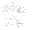
- FIG. 2 is a diagram showing a structure of a coupler 50 for connecting the contact pressure sensor 20 and the main body 30.
- FIG. 2A shows a state where a contact pressure sensor (not shown) is connected to the main body via the coupler.
- b) is a diagram showing a state in which the coupler is locked to the main body by a locking mechanism.
- the coupler structure for connecting the contact pressure sensor 20 and the main body 30 has a cylindrical tube 51 composed of five hard tubes provided at the tip of a tube 23 connected to the sensor element 22 as shown in FIG. Are provided on the main body side facing the cylindrical tube 51 of the coupler 50, and the cylindrical tube 51 is fitted in a watertight state. It is formed with a socket part.
- FIG. 2B shows a concave groove (not shown) in which a lock claw 52 provided on the back surface of the coupler 50 is provided on the back surface of the main body 30 when the coupler 50 is fitted and connected to the socket portion of the main body 30.
- a lock mechanism that locks and retains is shown. When the lock is released, the lock claw 52 is lifted and removed from the concave groove against the force of the spring applied to the claw 52, and the coupler 50 is pulled out from the main body 30.
- symbol 39 in a figure has shown the lid
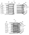
- FIG. 3 shows a coupler mechanism comprising a coupler concave portion provided in the main body and a coupler convex portion connected to the contact pressure sensor.
- (A) shows a state before coupling
- (b) shows a coupling state. It is shown.
- the coupler 50 is provided with five hard cylindrical tubes 51 arranged in parallel, and the tubes 23 extending from the sensor elements 22 are connected to the cylindrical tubes 51, respectively.
- the main body 30 is provided with five fitting holes 38 at positions facing the respective cylindrical tubes 51.
- An O-ring 38 a is disposed at the entrance of each fitting hole 38 and forms a watertight state with respect to the fitting of the cylindrical tube 51.
- a pressure sensor 40 (for example, a silicon pressure sensor) that measures air pressure is fixedly disposed at the end of each fitting hole 38, and the cylindrical tube 51 is placed in the fitting hole 38.
- a predetermined amount of air in the fitting hole 38 flows into the sensor element 22 through the tube 23, and an amount of air necessary for measuring the contact pressure is enclosed in the sensor element 22. It is like that.
- the coupler 50 by connecting the coupler 50 to the main body 30, the amount of air enclosed in the sensor element 22 is 0.7 ml, and the signal from the pressure sensor 40 at that time is set to display 0.0 mmHg. Yes.
- (b) shows a state in which the coupler 50 is completely fitted into the main body 30.
- FIG. 4 is a block diagram showing an electric circuit of the main body.
- 40 is a pressure sensor
- 41 is an A / D converter
- 42 is a digital / voltage converter
- 43 is a voltage / pressure converter
- 44 is an LCD output device
- 45 Indicates memory.
- the main body 30 is provided with a pressure sensor 40 at the end of each fitting hole 38.
- the output signal of the pressure sensor 40 is A / D converted by an A / D converter 41 and converted into a digital signal.
- the output is converted into a voltage by the digital / voltage converter 42, and the converted voltage value is converted into a pressure value by the voltage / pressure converter 43, and a numerical value (unit) is applied to the liquid crystal display 31 through the LCD output unit 44. mmHg) or an image.
- the memory 45 is a non-volatile memory that can store pressure data acquired by operating the memory button 36.
- SW1 to SW5 are switches corresponding to the start button 33, the guidance button 34, the power switch 35, the memory button 36, and the feed button 37.
- FIG. 5 shows a flowchart relating to a contact pressure measuring method
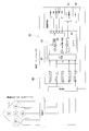
- FIG. 6A illustrates the contact pressure to each sensor element displayed on the main body liquid crystal display when the contact pressure measuring device is in the guidance mode.
- (B) shows a state in which the contact pressure to each sensor element changes by moving the contact pressure sensor.
- the contact pressure sensor 20 is set in the main body 30 via the coupler 50, and after the contact pressure sensor 20 is sandwiched between the patient and the bedding, the power switch 35 is turned on. Then, as shown in FIG. 1, a schematic external appearance of the substantially rhombic contact pressure sensor 20 is displayed on the liquid crystal display 31, a number is displayed at the position of each sensor element 22, and 0.0 mmHg is displayed on the lower side. The A state where no pressure is applied to the contact pressure sensor 20 is shown.
- the guidance button 34 when the guidance button 34 is turned ON, the contact pressure to each sensor element 22 is simultaneously displayed on the liquid crystal display 31 at the display position corresponding to the arrangement state of each sensor element 22 on the external schematic diagram of the contact pressure sensor. Let At this time, a “guidance” mark is displayed in the liquid crystal display 31 to enter the guidance mode. By using this guidance mode, it is possible to visually recognize which sensor element is most subjected to the contact pressure.
- the graphic display displays the strength of the contact pressure applied to the five sensor elements 22 in a four-stage concentric circle graph.
- the single circle is less than 30.0 mmHg
- the double circle is less than 60.0 mmHg
- the triple circle is less than 90.0 mmHg
- the quadrant is 91.0 mmHg or more, and is displayed in order from the outside. It has become.
- the contact pressure sensor 20 is moved so that the sensor element 22 showing the highest contact pressure becomes the sensor element of No. 1 which is the sensor element in the center. Thereafter, the start button 33 is turned on. By doing so, “normal” is displayed on the liquid crystal display 31, and the maximum value of the contact pressure to the sensor element of No. 1 can be measured after a certain period of time has elapsed in the normal mode. At this time, the maximum contact pressure is displayed as a numerical value (unit: mmHg) on the liquid crystal display 31.
- the measured value for each sensor element 22 is displayed in the number of circles, and the number and graph of the sensor element 22 that has measured the maximum value are flashing.
- the measured value for each sensor element 22 can be viewed as a numerical value (unit: mmHg).
- Measured values can be stored by pressing the memory button 36 after measuring the contact pressure.
- the memory number at the upper right of the measured value blinks twice and the data is stored in the memory 45. Since the contact pressure can be continuously measured after the memory (start button 33 is turned on), the measurement and memory storage are alternately performed. Changes and the like can be displayed on the liquid crystal display and visually recognized.
- the guidance button 34 is turned on to enter the guidance mode, and the start button 33 is pressed (for 2 seconds or longer) to set the long term mode.
- the contact pressure of the sensor element 22 can be measured sequentially at intervals of 0.8 seconds and displayed on the liquid crystal display with a graph and a numerical value. By doing so, it becomes easier to visually recognize temporal changes in contact pressure.
- the power switch 35 is turned off or the start button 33 is pressed again to return to the normal mode.
- the measurement interval is set to 0.8 seconds, but this is an example, and an optimal time interval may be set.
- the memory 45 has 25 memory maximum values, the latest measurement value is the memory number 01, and the memory number is sequentially decreased from the new measurement value to the old measurement value.
- “memory 01” is displayed in the liquid crystal display 31 and blinks, and each time the feed button 37 is pressed, the previous measurement value is displayed. Note that the memory number can be fast-forwarded when the feed button 37 is pressed and held. Further, the transition from the memory mode to the normal mode is performed by pressing the start button 33.
- the memory button 36 When the memory button 36 is pressed again while the memory number is displayed by the above operation, the memory number stops blinking and the sensor element 22 number and the pie chart blink. Each time the feed button 37 is pressed, the measured values of the sensor elements 22 can be displayed in order.
- the power switch 35 When the power switch 35 is turned on while pressing the “memory button” in the power switch OFF state, all data stored in the memory 45 can be erased.
- the power switch, the start button, the guidance button, the memory button, the feed button, and the like are referred to. It is not limited, and includes those for performing similar operations.
- the contact pressure measurement method has been described for measuring the contact pressure between the patient and the bedding.
- the present invention is not limited to this, and the contact pressure between other objects can also be measured. it can.
- a contact pressure sensor is sandwiched between them to measure the position where the center of gravity is applied, or to check whether the object is horizontal.
Landscapes
- Health & Medical Sciences (AREA)
- Life Sciences & Earth Sciences (AREA)
- Medical Informatics (AREA)
- Molecular Biology (AREA)
- Veterinary Medicine (AREA)
- Biophysics (AREA)
- Pathology (AREA)
- Engineering & Computer Science (AREA)
- Biomedical Technology (AREA)
- Heart & Thoracic Surgery (AREA)
- Public Health (AREA)
- Physics & Mathematics (AREA)
- Surgery (AREA)
- Animal Behavior & Ethology (AREA)
- General Health & Medical Sciences (AREA)
- Dentistry (AREA)
- Oral & Maxillofacial Surgery (AREA)
- Dermatology (AREA)
- Measuring And Recording Apparatus For Diagnosis (AREA)
- Force Measurement Appropriate To Specific Purposes (AREA)
- Invalid Beds And Related Equipment (AREA)
Abstract
患者と寝具との間の接触圧を位置関係をふまえて高精度に測定できる接触圧測定方法を提供する。 内部にエアが封入され押圧されると連結されたチューブを介して外部にエア圧力を加えるセンサ素子を中央部に1個とその回りに同心円上に複数備えた接触圧センサと、接触圧センサが接続される本体とを有し、本体は電源スイッチ、スタートボタン、ガイダンスボタン、メモリボタン、メモリ及び液晶ディスプレイを有し、接触圧センサの外観模式図が液晶ディスプレイに表示されるとともに、接触圧センサに接触圧が加わると外観模式図上の各センサ素子の配置状態に対応してそれぞれの接触圧が表示され、続いて、最高の接触圧を示すセンサ素子を外観模式図上の中央部に位置するセンサ素子となるように接触圧センサを移動させ、その後スタートボタンをONすることにより、中央部に位置するセンサ素子への接触圧の最高値を測定する。
Description
本発明は、例えば、ベッドに寝ている患者などの身体の各部位と寝具との接触圧を簡単に測定し、さらに当該測定結果をメモリ保存させたり、視覚的に認識させやすくすることのできる接触圧測定方法に関するものである。
近年、施設や病院の看護あるいは介護の現場において、寝たきりの患者を対象とした看護や介護は人口の高齢化とともに増加の一途をたどっている。このような現場においては、患者は持続的な圧迫を長時間にわたって受けることが多く、褥瘡(床ずれ)の危険にさらされている。この圧迫を軽減することによって褥瘡の発生を予防しようとする考えのもとに、現在、エアーマットレスをはじめとする各種の褥瘡予防用具が国内外で流通している。
また、このような対策以外にも、実際に患者のどの部位にどの程度の圧力がかかるのかを知る必要が有るため、各種の接触圧測定装置が開発されている。例えば、ベッド一面に多数の感圧センサを敷き詰めて、これらのセンサからの信号をコンピュータによって解析し、圧力分布を色分け表示するようにしたものがある。このような装置は、研究用として用いられるもので、オーダーメイドのため著しく高価でかつ大型な装置となり、使用の際には高度な知識や技術を必要とするものである。
このため、実際の介護現場では患者の体表面がどのような圧迫を受ける環境下にあるのか、さらには褥瘡予防用具の使用による圧力環境の改善度合いなどを具体的に知ることは困難といえる。このため、看護等に従事するスタッフは目に見えない圧力を原因とする褥瘡発生の危険度を知る方法が少なく、本来予防することが可能な褥瘡を発生させてしまったりあるいは悪化させてしまっているのが現状である。
そこで、この点の課題を解決するために、特許文献1に示すような、簡単な構造で患者の体表面と寝具との間に生じる接触圧を測定する接触圧測定装置が提案されている。
この接触圧測定装置は、2枚のエア不透過性シートの間に、押圧を解除すると元の形状に復帰する発泡プラスチックを押圧しない状態で挟むとともに、該発泡プラスチックの近傍から前記エア不透過性シートの外側まで延びるチューブを配置して、これら発泡プラスチック及びチューブの周囲の前記エア不透過性シートを互いに接着させて構成した接触圧センサを有しており、該接触圧センサのチューブの先端部に配置された圧力検出器と、該圧力検出器の圧力信号を受け、圧力検出器からの信号が単一の場合にはそのまま出力し複数の場合にはこれらの信号値の平均値あるいは最大値のいずれかを出力する変換回路と、該変換回路の出力信号をデジタル表示する表示部とを備えたものである。
そして、特許文献1によると、接触圧を測定する際には、患者と寝具との間に接触圧センサを挟み込んだ状態で、装置の電源をONし、表示部に、接触圧センサへの接触圧を表示させるといった接触圧測定方法を用いていることがわかる。
上記特許文献1に記載の接触圧測定装置における測定方法では、接触圧センサが複数の場合は、これらのセンサ信号の平均値或いは最大値のいずれかを出力するようになっているが、患者のどの部位が最大の接触圧を受けているのか明瞭ではなかったので、接触圧が最高となる位置を所望の位置へと移動させることが非常に難しいという問題があった。さらに、測定結果が数値程度の表示しかされないため、接触圧センサに加わる接触圧の時間的な変化を読みとることが困難であった。また、最大の接触圧を生じている患者の身体部位がどの方向にあるのか明瞭ではなかった。
本発明は、上述のような課題に鑑みなされたもので、患者と寝具との間の接触圧を位置関係をふまえて高精度に測定でき、さらに測定結果をメモリに保存することや、視覚的に認識しやすくする接触圧測定方法を提供することにある
請求項1記載の接触圧測定方法は、内部にエアが封入され押圧されると連結されたチューブを介して外部にエア圧力を加えるセンサ素子を中央部に1個とその回りに同心円上に複数備えた接触圧センサと、該接触圧センサが接続される本体とを有し、該本体は電源スイッチ、通常モードとなるスタートボタン、ガイダンスモードとなるガイダンスボタン、メモリボタン、メモリ及び液晶ディスプレイを有し、前記接触圧センサが接続され、電源ON状態にすると該接触圧センサの外観模式図が前記液晶ディスプレイに表示されるとともに、接触圧センサに接触圧が加わると前記外観模式図上の前記各センサ素子の配置状態に対応してそれぞれの接触圧が表示されるように構成された接触圧測定装置の接触圧測定方法であって、接触圧を測定する際に、先ず前記接触圧センサを測定部位と該測定部位が接触する物との間に挟み込み、前記電源スイッチをONしたあと前記ガイダンスボタンをONして、前記液晶ディスプレイに前記外観模式図上の前記各センサ素子の配置状態に対応した表示位置に各センサ素子への接触圧を表示させ、続いて、最高の接触圧を示すセンサ素子を前記外観模式図上の中央部に位置するセンサ素子となるように前記接触圧センサを移動させ、その後スタートボタンをONすることにより、当該中央部に位置するセンサ素子への接触圧の最高値を測定することを特徴としている。
請求項2記載の発明は、請求項1の接触圧測定方法において、前記センサ素子への接触圧を測定し、続いて、当該センサ素子への接触圧の最高値が確定したあと、前記メモリボタンをONすることにより、その数値を前記メモリに記憶させ、その後、続けて前記スタートボタンをONし、接触圧を測定することを特徴としている。
また、請求項3記載の発明は、請求項1の接触圧測定方法において、前記スタートボタンを長押ししてONすることにより、前記接触圧センサの各センサ素子の接触圧を所定間隔で順次測定させるとともに、前記液晶ディスプレイに当該測定結果をグラフと数値で表示させることで、前記各センサ素子への接触圧の時間的変化を認識できるようにすることを特徴としている。
請求項1記載の発明によれば、接触圧を測定する際に、先ず接触圧センサを測定部位と該測定部位が接触する物との間に挟み込み、電源ONしたあとガイダンスボタンをONすることで、液晶ディスプレイに各センサ素子の配置状態に対応した表示位置に各センサ素子への接触圧が表示され、最高の接触圧を示すセンサ素子を接触圧センサの中央部に位置するセンサ素子となるように接触圧センサを移動させることができる。そして、その後スタートボタンをONして接触圧が最高となる値を測定することが容易にできる。
請求項2記載の発明によれば、スタートボタンをONして、接触圧を測定し、接触圧の最高値が確定したあと、メモリスイッチをONすることで、その数値をメモリに記憶させることができ、その後スタートボタンをONすると続けて接触圧が測定するため、メモリへの記憶と接触圧の測定を交互に行うことができる。そして、メモリに保存された各センサ素子への接触圧を読み出すことができるため、これらの時間的経過を見ることができ、患者への対応が容易になる。
請求項3記載の発明によれば、電源スイッチをONしたあと、ガイダンスボタンをONしてガイダンスモードにし、更にスタートボタンを長押しすることで、接触圧センサの各センサ素子の接触圧を所定間隔で順次測定させ、液晶ディスプレイにグラフと数値で表示させることができるため、接触圧の時間的変化がリアルタイムにわかり、その結果、各部位の接触圧の変化を視覚的に認識しやすくなり、どの部位に特に注意を払うべきかがわかり易くなる。
以下、本発明の実施の形態について、図面を参照して説明する。
図1は、本発明に係る接触圧測定方法を実施するための接触圧測定装置を示したもので、10は接触圧測定装置、20は接触圧センサ、21は外袋、22はセンサ素子、23はチューブ、30は本体、31は液晶ディスプレイ、32はプラスチック筐体、33はスタートボタン、34はガイダンスボタン、35は電源スイッチ、36はメモリボタン、37は送りボタン、50はカプラを示している。
図1は、本発明に係る接触圧測定方法を実施するための接触圧測定装置を示したもので、10は接触圧測定装置、20は接触圧センサ、21は外袋、22はセンサ素子、23はチューブ、30は本体、31は液晶ディスプレイ、32はプラスチック筐体、33はスタートボタン、34はガイダンスボタン、35は電源スイッチ、36はメモリボタン、37は送りボタン、50はカプラを示している。
接触圧測定装置10は、図に示すように、患者と寝具の間に挟む接触圧センサ20と、液晶ディスプレイ31を有する本体30とを備えており、接触圧センサ20と本体30とはカプラ50で接続する構造になっている。
接触圧センサ20は、外側が略菱形の外袋21で形成されており、その内部に風船状のセンサ素子22が収納されている。センサ素子22は、厚さ約0.3mmの2枚のエア不透過性シートをチューブ23を挟んだ状態でその周縁部を溶着したものである。接触圧センサ20は、この実施例においては、5個のセンサ素子22を有しており、中央部に1個(番号1)とそれを取り巻く円周上に他のセンサ素子22(番号2,3,4,5)を配置したのである。なお、センサ素子22のエア不透過性シートは、ポリウレタンフィルム又は塩化ビニルフィルムなどを用いることができ、その厚さは0.02mm~0.5mmの範囲で適宜設定することができる。また、チューブ23は外形1mmφ程度の耐圧性のあるポリウレタン製などを使用する。
各チューブ23はそれぞれ各センサ素子22に連通し、外袋21から延びてカプラ50に連結されている。一方、本体30は、プラスチック筐体32を有しており、その表面に液晶ディスプレイ31が配置されている。また、該液晶ディスプレイ31の下側には、スタートボタン33、Gマークで示されるガイダンスボタン34、電源スイッチ35、メモリボタン36、それに送りボタン37等が設けられている。
また、液晶ディスプレイ31には、電源スイッチ35がONされると、接触圧センサ20の外観模式図が表示され、そこに各センサ素子22の番号が配置状態に対応して表示される。ここで模式外観図とは、接触圧センサ20が略菱形であるので、その菱形の線と、その中に収納されている5個のセンサ素子22の配置状態に対応した番号が表されているものである。なお、液晶ディスプレイ31に表示されるその他の各表示については後述する。
続いて、本発明に係る接触圧測定方法に用いる接触圧測定装置のカプラ構造について図面を参照しながら説明する。図2は、接触圧センサ20と本体30を接続させるカプラ50の構造を示した図で、(a)は、カプラを介して接触圧センサ(不図示)を本体に接続するところを示し、(b)は、本体に対して、ロック機構によりカプラをロックした状態を示した図である。
接触圧センサ20と本体30とを接続するカプラ構造は、図2(a)に示すように、センサ素子22に連結されたチューブ23の先端に設けられた5本の硬質管からなる円筒管51が並列状態で配置されたプラグ状のカプラ50と、該カプラ50の円筒管51に対向して、本体側に設けられ、前記円筒管51が水密状態で嵌合する嵌合穴38を備えたソケット部とで形成されている。
図2(b)は、カプラ50を本体30のソケット部に嵌合接続させたときに、カプラ50の背面に設けられたロック爪52が本体30の背面に設けられた凹溝(不図示)にロックして抜け留めとなるロック機構を示している。ロックを外すときは、前記爪52に加えられているバネの力に抗してロック爪52を持ち上げ凹溝から外してカプラ50を本体30から引き抜くことになる。なお、図中の符号39は本体30の電池(006P)を脱着するための蓋を示している。電池の代わりに、ACアダプタによって電源を供給することもできるようになっている。
次に、カプラ構造の詳細について、図面を参照しながら説明する。図3は、本体に設けられたカプラ凹部と接触圧センサに連結するカプラ凸部からなるカプラ機構を示しており、(a)は、結合前の状態を示し、(b)は、結合状態を示したものである。
(a)に示すように、カプラ50は硬質な円筒管51が5本並設されていて、各センサ素子22から延びたチューブ23がそれぞれ各円筒管51に接続されている。一方また、本体30には、前記各円筒管51と対向する位置に5個の嵌合穴38が設けられている。各嵌合穴38の入口にあたるところにOリング38aが配置されていて、前記円筒管51の嵌合に対して水密状態を形成する。
また、それぞれの嵌合穴38の終端部には、空気(エア)圧を測定する圧力センサ40(例えば、シリコン圧力センサ)が固定配置されており、前記円筒管51が前記嵌合穴38に差し込まれると、該嵌合穴38中の空気の所定量が前記チューブ23を介してセンサ素子22内へ流入し、接触圧を測定するために必要な量の空気をセンサ素子22内に封入するようになっている。実際には、カプラ50を本体30に接続することで、センサ素子22内に封入する空気量は0.7mmlで、その時の圧力センサ40からの信号は0.0mmHgを表示するようにセットされている。なお、(b)はカプラ50を本体30に完全に嵌め込んだ状態を示したものである。
次に、本体30内に設けられている電気回路について図面を参照しながら説明する。図4は、本体の電気回路を示すブロック図で、40は圧力センサ、41はA/D変換器、42はデジタル・電圧変換器、43は電圧・圧力変換器、44はLCD出力器、45はメモリを示している。
本体30には、前記各嵌合穴38の終端部にそれぞれ圧力センサ40が設けられており、圧力センサ40の出力信号はA/D変換器41によりA/D変換され、デジタル信号に変換された出力はデジタル・電圧変換器42で電圧に変換され、さらに変換された電圧値は電圧・圧力変換器43をよって圧力値に変換されてLCD出力器44を介して液晶ディスプレイ31に数値(単位mmHg)や画像として表示される。
また、メモリ45は不揮発性のメモリで、メモリボタン36を操作することで取得した圧力データを記憶することができるようになっている。SW1~SW5は、スタートボタン33、ガイダンスボタン34、電源スイッチ35、メモリボタン36、送りボタン37に対応させたスイッチである。
続いて、この接触圧測定装置10を用いた接触圧の測定方法について図1、5、6を参照しながら説明する。図5は、接触圧の測定方法に関するフローチャートを示し、図6(a)は、接触圧測定装置がガイダンスモードのときに、本体液晶ディスプレイに表示される各センサ素子への接触圧を例示したもので、(b)は、接触圧センサを移動させることで、各センサ素子への接触圧が変化する状態を示したものである。
先ず、本体30にカプラ50を介して接触圧センサ20をセットし、患者と寝具との間に接触圧センサ20を挟み込んだあと、電源スイッチ35をONする。そうすると、図1に示すように、液晶ディスプレイ31に略菱形の接触圧センサ20の模式外観が表示されるとともに各センサ素子22の位置に番号が表示され、かつ下側に0.0mmHgと表示される。接触圧センサ20に圧力が掛かっていない状態を示している。
次に、ガイダンスボタン34をONすることにより、液晶ディスプレイ31に接触圧センサの外観模式図上の各センサ素子22の配置状態に対応した表示位置に各センサ素子22への接触圧を同時に図形表示させる。このとき、液晶ディスプレイ31内には、「ガイダンス」マークが表示され、ガイダンスモードとなる。このガイダンスモードにすることによって、どのセンサ素子に最も接触圧が加えられているかを視覚的に認識できるようになるわけである。
なお、図形表示は、図6(a)に示すように、5個のセンサ素子22に掛かる接触圧の強さをそれぞれ4段階の同心円の円グラフで表示される。本実施例では、1重円は30.0mmHg未満、2重円は60.0mmHg未満、3重円は90.0mmHg未満、4重円は91.0mmHg以上を表し、外側から順に表示されるようになっている。
次に、最高の接触圧を示すセンサ素子22が中央部のセンサ素子である番号1番のセンサ素子となるように、図6(b)に示すように、接触圧センサ20を移動させて、その後スタートボタン33をONする。そうすることにより、液晶ディスプレイ31には「通常」と表示され、通常モードとなって一定時間経過後に当該番号1番のセンサ素子への接触圧の最高値を測定させることができる。このとき液晶ディスプレイ31には最高接触圧が数値(単位mmHg)で表示される。
このときも、センサ素子22毎の計測値は円の数で表示され、最高値を計測したセンサ素子22の番号とグラフが点滅しており、送りボタン37を押すことで、順に1~5番のセンサ素子22毎の測定値を数値(単位mmHg)として見ることができるようにもなっている。なお、ガイダンスボタン34をONしない場合は、通常のモードで接触圧の測定を行うことができる。
測定値をメモリするには、接触圧の測定後、メモリボタン36を押すことで行える。測定値右上のメモリ番号が2回点滅してデータがメモリ45に記憶される仕組みとなっている。メモリ後も続いてそのまま継続して接触圧を測定することができるようになっているため(スタートボタン33をON)、測定・メモリ記憶を交互にしていき、測定作業後に、接触圧の時間的変化等を液晶ディスプレイに表示させ、視覚的に認識することができる。
また、電源スイッチ35をONしたあと、ガイダンスボタン34をONしてガイダンスモードにし、更にスタートボタン33を長押し(2秒以上)することで、ロングタームモードに設定でき、接触圧センサ20の各センサ素子22の接触圧を0.8秒間隔で順次測定し、液晶ディスプレイにグラフと数値で表示させることができる。そうすることで、接触圧の時間的変化を視覚的に認識しやすくなるわけである。なお、ロングタームモードを終了させるには、電源スイッチ35を切るか或いは再度スタートボタン33を押して通常モードにする。本実施例では、測定間隔を0.8秒としているが、これは一例であり、最適な時間間隔を設定すればよい。
続いて、メモリ機能について、さらに説明する。
メモリ45に記憶させるメモリ最大値は25個で、最新の測定値がメモリ番号01となり、新しい測定値から古い測定値へメモリ番号が順に繰り下がっていく構成となっている。通常モード時(「通常」マークが表示されている状態)に、メモリボタン36を2秒以上長押しすることで、メモリに記録されている最新の測定値(メモリ番号01)を液晶ディスプレイに表示させることができる。この状態では、液晶ディスプレイ31内には、「メモリ01」と表示がでて、点滅しており、送りボタン37を押す毎に、1つ前の測定値が表示される構成となっている。なお、送りボタン37を長押しすると、メモリ番号の早送りができるように構成されている。また、メモリモードから通常モードへの移行は、スタートボタン33を押すことで行われる。
メモリ45に記憶させるメモリ最大値は25個で、最新の測定値がメモリ番号01となり、新しい測定値から古い測定値へメモリ番号が順に繰り下がっていく構成となっている。通常モード時(「通常」マークが表示されている状態)に、メモリボタン36を2秒以上長押しすることで、メモリに記録されている最新の測定値(メモリ番号01)を液晶ディスプレイに表示させることができる。この状態では、液晶ディスプレイ31内には、「メモリ01」と表示がでて、点滅しており、送りボタン37を押す毎に、1つ前の測定値が表示される構成となっている。なお、送りボタン37を長押しすると、メモリ番号の早送りができるように構成されている。また、メモリモードから通常モードへの移行は、スタートボタン33を押すことで行われる。
上記操作でメモリ番号が表示されているときに、再度メモリボタン36を押すと、メモリ番号の点滅が止まりセンサ素子22の番号と円グラフが点滅する。送りボタン37を押す毎に各センサ素子22の測定値が順に表示させることができる。なお、電源スイッチOFF状態で、「メモリボタン」を押しながら電源スイッチ35をONすると、メモリ45に記憶されていたデータは全て消去することができるようになっている。
なお、特許請求の範囲や上記実施の形態において、電源スイッチ、スタートボタン、ガイダンスボタン、メモリボタン、送りボタン等の言い方をしているが、機能を説明するための名称であって、この名称に限定したものではなく、同類の操作を行うためのものはこれらに含まれる。
上記実施の形態では、この接触圧測定方法を患者と寝具の間の接触圧を測定することについて説明したが、これに限らず、他の物と物との間の接触圧を測定することもできる。例えば、平らな面に何か物体を置くときに、その間に接触圧センサを挟んで、重心の掛かる位置の測定とか、或いは水平になっているか否かなどを調べることもできる。
10 接触圧測定装置
20 接触圧センサ
21 外体
22 センサ素子
23 チューブ
30 本体
31 液晶ディスプレイ
32 筐体
33 スタートボタン
34 ガイダンスボタン
35 電源スイッチ
36 メモリボタン
37 送りボタン
38 嵌合穴
38a Oリング
40 圧力センサ
50 カプラ
51 円筒管
52 ロック爪
20 接触圧センサ
21 外体
22 センサ素子
23 チューブ
30 本体
31 液晶ディスプレイ
32 筐体
33 スタートボタン
34 ガイダンスボタン
35 電源スイッチ
36 メモリボタン
37 送りボタン
38 嵌合穴
38a Oリング
40 圧力センサ
50 カプラ
51 円筒管
52 ロック爪
Claims (3)
- 内部にエアが封入され押圧されると連結されたチューブを介して外部にエア圧力を加えるセンサ素子を中央部に1個とその回りに同心円上に複数備えた接触圧センサと、該接触圧センサが接続される本体とを有し、該本体は電源スイッチ、通常モードとなるスタートボタン、ガイダンスモードとなるガイダンスボタン、メモリボタン、メモリ及び液晶ディスプレイを有し、前記接触圧センサが接続され、電源ON状態にすると該接触圧センサの外観模式図が前記液晶ディスプレイに表示されるとともに、接触圧センサに接触圧が加わると前記外観模式図上の前記各センサ素子の配置状態に対応してそれぞれの接触圧が表示されるように構成された接触圧測定装置の接触圧測定方法であって、
接触圧を測定する際に、先ず前記接触圧センサを測定部位と該測定部位が接触する物との間に挟み込み、前記電源スイッチをONしたあと前記ガイダンスボタンをONして、前記液晶ディスプレイに前記外観模式図上の前記各センサ素子の配置状態に対応した表示位置に各センサ素子への接触圧を表示させ、続いて、最高の接触圧を示すセンサ素子を前記外観模式図上の中央部に位置するセンサ素子となるように前記接触圧センサを移動させ、その後スタートボタンをONすることにより、当該中央部に位置するセンサ素子への接触圧の最高値を測定することを特徴とする接触圧測定方法。 - 前記センサ素子への接触圧を測定し、続いて、当該センサ素子への接触圧の最高値が確定したあと、前記メモリボタンをONすることにより、その数値を前記メモリに記憶させ、その後、続けて前記スタートボタンをONし、接触圧を測定することを特徴とする請求項1記載の接触圧測定方法。
- 前記スタートボタンを長押ししてONすることにより、前記接触圧センサの各センサ素子の接触圧を所定間隔で順次測定させるとともに、前記液晶ディスプレイに当該測定結果をグラフと数値で表示させることで、前記各センサ素子への接触圧の時間的変化を認識できるようにすることを特徴とする請求項1記載の接触圧測定方法。
Priority Applications (1)
| Application Number | Priority Date | Filing Date | Title |
|---|---|---|---|
| CN201080037324.2A CN102483365B (zh) | 2009-08-25 | 2010-07-07 | 触压量测方法 |
Applications Claiming Priority (2)
| Application Number | Priority Date | Filing Date | Title |
|---|---|---|---|
| JP2009-194607 | 2009-08-25 | ||
| JP2009194607A JP5107979B2 (ja) | 2009-08-25 | 2009-08-25 | 接触圧測定方法 |
Publications (1)
| Publication Number | Publication Date |
|---|---|
| WO2011024372A1 true WO2011024372A1 (ja) | 2011-03-03 |
Family
ID=43627495
Family Applications (1)
| Application Number | Title | Priority Date | Filing Date |
|---|---|---|---|
| PCT/JP2010/004435 Ceased WO2011024372A1 (ja) | 2009-08-25 | 2010-07-07 | 接触圧測定方法 |
Country Status (3)
| Country | Link |
|---|---|
| JP (1) | JP5107979B2 (ja) |
| CN (1) | CN102483365B (ja) |
| WO (1) | WO2011024372A1 (ja) |
Cited By (1)
| Publication number | Priority date | Publication date | Assignee | Title |
|---|---|---|---|---|
| CN106726262A (zh) * | 2016-12-13 | 2017-05-31 | 王佃云 | 一种内科护理用简易辅助翻身器 |
Families Citing this family (6)
| Publication number | Priority date | Publication date | Assignee | Title |
|---|---|---|---|---|
| JP6081767B2 (ja) | 2011-10-25 | 2017-02-15 | 諒 黒沢 | 治療装置 |
| JPWO2014045498A1 (ja) * | 2012-09-24 | 2016-08-18 | テルモ株式会社 | 情報処理装置、情報処理装置の制御方法、圧分布計測システム、プログラムおよび記憶媒体 |
| WO2018043051A1 (ja) * | 2016-09-05 | 2018-03-08 | オムロンヘルスケア株式会社 | 力検出装置 |
| JP6654161B2 (ja) | 2016-09-05 | 2020-02-26 | オムロンヘルスケア株式会社 | 力検出装置 |
| WO2018186348A1 (ja) * | 2017-04-04 | 2018-10-11 | 学校法人 中央大学 | 筋収縮検出センサ |
| US11439871B2 (en) * | 2019-02-27 | 2022-09-13 | Conzian Ltd. | System and method for rehabilitation |
Citations (10)
| Publication number | Priority date | Publication date | Assignee | Title |
|---|---|---|---|---|
| JPH0520709U (ja) * | 1991-09-03 | 1993-03-19 | コーリン電子株式会社 | 脈波検出装置 |
| JPH06502317A (ja) * | 1990-11-06 | 1994-03-17 | バイオ クリニック コーポレイション | 液体を満たしたフローテーション・マットレス |
| JP2000111420A (ja) * | 1998-10-06 | 2000-04-21 | Keepu:Kk | 接触圧測定センサ及びそれを備えた接触圧測定装置 |
| JP2001149185A (ja) * | 1999-10-19 | 2001-06-05 | Thomas Hilfen Hilbeg Gmbh & Co Kg | 横臥している人体からの値を測定する装置および方法、および圧力センサー |
| JP2002098601A (ja) * | 2000-09-26 | 2002-04-05 | Molten Corp | ずれ力測定装置 |
| JP2004160186A (ja) * | 2002-09-20 | 2004-06-10 | Nippon Seimitsu Sokki Kk | 健康指標測定のための電子機器及びその制御方法 |
| JP2005176895A (ja) * | 2003-12-16 | 2005-07-07 | Nakajima Medical Supply Kk | ベッドおよびベッドに使用される床ずれ防止装置 |
| JP2007319233A (ja) * | 2006-05-30 | 2007-12-13 | Toshiba Corp | 生体情報計測装置 |
| JP2008012161A (ja) * | 2006-07-07 | 2008-01-24 | Omron Healthcare Co Ltd | 脈波検出装置およびプログラム |
| JP2009072438A (ja) * | 2007-09-21 | 2009-04-09 | Fujitsu Ltd | 指先適正押圧状態報知方法及び装置 |
Family Cites Families (3)
| Publication number | Priority date | Publication date | Assignee | Title |
|---|---|---|---|---|
| US4114928A (en) * | 1977-01-10 | 1978-09-19 | Fmc Corporation | High force connecting mechanism |
| TWI224964B (en) * | 2002-03-25 | 2004-12-11 | Molten Corp | Detecting device for cause of pressure sores |
| CN100453989C (zh) * | 2007-06-19 | 2009-01-21 | 杭州电子科技大学 | 阵列压电传感器 |
-
2009
- 2009-08-25 JP JP2009194607A patent/JP5107979B2/ja active Active
-
2010
- 2010-07-07 CN CN201080037324.2A patent/CN102483365B/zh active Active
- 2010-07-07 WO PCT/JP2010/004435 patent/WO2011024372A1/ja not_active Ceased
Patent Citations (10)
| Publication number | Priority date | Publication date | Assignee | Title |
|---|---|---|---|---|
| JPH06502317A (ja) * | 1990-11-06 | 1994-03-17 | バイオ クリニック コーポレイション | 液体を満たしたフローテーション・マットレス |
| JPH0520709U (ja) * | 1991-09-03 | 1993-03-19 | コーリン電子株式会社 | 脈波検出装置 |
| JP2000111420A (ja) * | 1998-10-06 | 2000-04-21 | Keepu:Kk | 接触圧測定センサ及びそれを備えた接触圧測定装置 |
| JP2001149185A (ja) * | 1999-10-19 | 2001-06-05 | Thomas Hilfen Hilbeg Gmbh & Co Kg | 横臥している人体からの値を測定する装置および方法、および圧力センサー |
| JP2002098601A (ja) * | 2000-09-26 | 2002-04-05 | Molten Corp | ずれ力測定装置 |
| JP2004160186A (ja) * | 2002-09-20 | 2004-06-10 | Nippon Seimitsu Sokki Kk | 健康指標測定のための電子機器及びその制御方法 |
| JP2005176895A (ja) * | 2003-12-16 | 2005-07-07 | Nakajima Medical Supply Kk | ベッドおよびベッドに使用される床ずれ防止装置 |
| JP2007319233A (ja) * | 2006-05-30 | 2007-12-13 | Toshiba Corp | 生体情報計測装置 |
| JP2008012161A (ja) * | 2006-07-07 | 2008-01-24 | Omron Healthcare Co Ltd | 脈波検出装置およびプログラム |
| JP2009072438A (ja) * | 2007-09-21 | 2009-04-09 | Fujitsu Ltd | 指先適正押圧状態報知方法及び装置 |
Cited By (2)
| Publication number | Priority date | Publication date | Assignee | Title |
|---|---|---|---|---|
| CN106726262A (zh) * | 2016-12-13 | 2017-05-31 | 王佃云 | 一种内科护理用简易辅助翻身器 |
| CN106726262B (zh) * | 2016-12-13 | 2019-06-04 | 王佃云 | 一种内科护理用简易辅助翻身器 |
Also Published As
| Publication number | Publication date |
|---|---|
| JP2011047711A (ja) | 2011-03-10 |
| CN102483365A (zh) | 2012-05-30 |
| JP5107979B2 (ja) | 2012-12-26 |
| CN102483365B (zh) | 2015-03-25 |
Similar Documents
| Publication | Publication Date | Title |
|---|---|---|
| JP5107979B2 (ja) | 接触圧測定方法 | |
| US8535246B2 (en) | System and method of reducing risk and/or severity of pressure ulcers | |
| TWI224964B (en) | Detecting device for cause of pressure sores | |
| CN103841884A (zh) | 压力监测系统和方法 | |
| JP4777453B2 (ja) | カプラ構造 | |
| CN103238152A (zh) | 用于预防压力损伤的形成的压力传感器组件和相关联的方法 | |
| JP2000111420A (ja) | 接触圧測定センサ及びそれを備えた接触圧測定装置 | |
| CN206166902U (zh) | 柔性智能织物传感器、智能床垫及其监测系统 | |
| US9480408B2 (en) | Home uterine activity monitoring | |
| US5838244A (en) | Interface pressure measurement device | |
| CA2506239A1 (en) | Blood presure measuring device and monitor system with wireless transmission of pressure signals | |
| KR20100047054A (ko) | 휴대용 손가락 악력기 | |
| TW201822739A (zh) | 床墊裝置以及照護系統 | |
| JP2011047710A (ja) | 接触圧測定装置 | |
| JP2013198618A (ja) | バイタル計測器 | |
| JP7171658B2 (ja) | 体動検出装置 | |
| EP1658807A1 (en) | Blood pressure measuring device and monitor system with wireless transmission of pressure signals | |
| CN201675922U (zh) | 健康检测装置 | |
| CN114631791A (zh) | 一种医用无线监护设备 | |
| KR102680441B1 (ko) | 착탈 가능한 휴대용 체온계가 구비된 혈압 측정 장치 | |
| CN216483603U (zh) | 一种便携式医用体温检测装置 | |
| CN215003951U (zh) | 一种可拓展的数据记录护士笔 | |
| CN206656662U (zh) | 一种使用方便的多功能医用软卷尺 | |
| JPH09304203A (ja) | 接触圧測定装置 | |
| JP2014064654A (ja) | バイタル計測器 |
Legal Events
| Date | Code | Title | Description |
|---|---|---|---|
| WWE | Wipo information: entry into national phase |
Ref document number: 201080037324.2 Country of ref document: CN |
|
| 121 | Ep: the epo has been informed by wipo that ep was designated in this application |
Ref document number: 10811431 Country of ref document: EP Kind code of ref document: A1 |
|
| NENP | Non-entry into the national phase |
Ref country code: DE |
|
| 122 | Ep: pct application non-entry in european phase |
Ref document number: 10811431 Country of ref document: EP Kind code of ref document: A1 |