WO2011002093A1 - 生体信号測定用装具 - Google Patents
生体信号測定用装具 Download PDFInfo
- Publication number
- WO2011002093A1 WO2011002093A1 PCT/JP2010/061362 JP2010061362W WO2011002093A1 WO 2011002093 A1 WO2011002093 A1 WO 2011002093A1 JP 2010061362 W JP2010061362 W JP 2010061362W WO 2011002093 A1 WO2011002093 A1 WO 2011002093A1
- Authority
- WO
- WIPO (PCT)
- Prior art keywords
- head
- electrode
- support
- hair band
- scalp
- Prior art date
Links
Images


Classifications
-
- A—HUMAN NECESSITIES
- A61—MEDICAL OR VETERINARY SCIENCE; HYGIENE
- A61B—DIAGNOSIS; SURGERY; IDENTIFICATION
- A61B5/00—Measuring for diagnostic purposes; Identification of persons
- A61B5/48—Other medical applications
- A61B5/4806—Sleep evaluation
- A61B5/4815—Sleep quality
-
- A—HUMAN NECESSITIES
- A61—MEDICAL OR VETERINARY SCIENCE; HYGIENE
- A61B—DIAGNOSIS; SURGERY; IDENTIFICATION
- A61B5/00—Measuring for diagnostic purposes; Identification of persons
- A61B5/24—Detecting, measuring or recording bioelectric or biomagnetic signals of the body or parts thereof
- A61B5/25—Bioelectric electrodes therefor
- A61B5/251—Means for maintaining electrode contact with the body
- A61B5/256—Wearable electrodes, e.g. having straps or bands
-
- A—HUMAN NECESSITIES
- A61—MEDICAL OR VETERINARY SCIENCE; HYGIENE
- A61B—DIAGNOSIS; SURGERY; IDENTIFICATION
- A61B5/00—Measuring for diagnostic purposes; Identification of persons
- A61B5/24—Detecting, measuring or recording bioelectric or biomagnetic signals of the body or parts thereof
- A61B5/25—Bioelectric electrodes therefor
- A61B5/263—Bioelectric electrodes therefor characterised by the electrode materials
-
- A—HUMAN NECESSITIES
- A61—MEDICAL OR VETERINARY SCIENCE; HYGIENE
- A61B—DIAGNOSIS; SURGERY; IDENTIFICATION
- A61B5/00—Measuring for diagnostic purposes; Identification of persons
- A61B5/24—Detecting, measuring or recording bioelectric or biomagnetic signals of the body or parts thereof
- A61B5/25—Bioelectric electrodes therefor
- A61B5/279—Bioelectric electrodes therefor specially adapted for particular uses
- A61B5/291—Bioelectric electrodes therefor specially adapted for particular uses for electroencephalography [EEG]
-
- A—HUMAN NECESSITIES
- A61—MEDICAL OR VETERINARY SCIENCE; HYGIENE
- A61B—DIAGNOSIS; SURGERY; IDENTIFICATION
- A61B5/00—Measuring for diagnostic purposes; Identification of persons
- A61B5/68—Arrangements of detecting, measuring or recording means, e.g. sensors, in relation to patient
- A61B5/6801—Arrangements of detecting, measuring or recording means, e.g. sensors, in relation to patient specially adapted to be attached to or worn on the body surface
- A61B5/6813—Specially adapted to be attached to a specific body part
- A61B5/6814—Head
-
- A—HUMAN NECESSITIES
- A61—MEDICAL OR VETERINARY SCIENCE; HYGIENE
- A61B—DIAGNOSIS; SURGERY; IDENTIFICATION
- A61B2562/00—Details of sensors; Constructional details of sensor housings or probes; Accessories for sensors
- A61B2562/02—Details of sensors specially adapted for in-vivo measurements
- A61B2562/0209—Special features of electrodes classified in A61B5/24, A61B5/25, A61B5/283, A61B5/291, A61B5/296, A61B5/053
-
- A—HUMAN NECESSITIES
- A61—MEDICAL OR VETERINARY SCIENCE; HYGIENE
- A61B—DIAGNOSIS; SURGERY; IDENTIFICATION
- A61B5/00—Measuring for diagnostic purposes; Identification of persons
- A61B5/24—Detecting, measuring or recording bioelectric or biomagnetic signals of the body or parts thereof
- A61B5/316—Modalities, i.e. specific diagnostic methods
- A61B5/398—Electrooculography [EOG], e.g. detecting nystagmus; Electroretinography [ERG]
-
- A—HUMAN NECESSITIES
- A61—MEDICAL OR VETERINARY SCIENCE; HYGIENE
- A61B—DIAGNOSIS; SURGERY; IDENTIFICATION
- A61B5/00—Measuring for diagnostic purposes; Identification of persons
- A61B5/68—Arrangements of detecting, measuring or recording means, e.g. sensors, in relation to patient
- A61B5/6887—Arrangements of detecting, measuring or recording means, e.g. sensors, in relation to patient mounted on external non-worn devices, e.g. non-medical devices
Definitions
- the present invention relates to an apparatus for measuring a biological signal, and is suitable in the technical field of acquiring a wave generated and transmitted in a living body as an electric signal.
- the present invention has been made in consideration of the above points, and an object of the present invention is to propose a biosignal measurement equipment which can improve the measurement accuracy without imposing an excessive burden on the subject.
- the present invention is a biosignal measurement equipment used for measuring a biosignal in the head, and has a support capable of supporting the head and an electrode provided on the support.
- the electrode according to the first aspect of the present invention comprises a plurality of teeth comprising an annular portion in which a pair of conductive wires are annularly formed, and a rod-like portion formed by winding the pair of wires in the opposite direction. One end of the rod-like portion of the plurality of teeth is fixed directly or indirectly to the support.
- the electrode according to the second invention comprises a plurality of wires, one end of the plurality of wires being fixed at equal intervals in the row direction and the column direction with respect to the surface facing the scalp in the support, from one end
- the root portion to the bending position between one end and the other end is in a state of being perpendicular to the surface and standing upright, and the portion from the bending position to the other end is bent obliquely to the root portion.
- the electrode according to the third aspect of the present invention comprises a plurality of conductive fibers, and the conductive fibers are fixed at a predetermined interval to a surface of which one end is opposed to the scalp in the support, and are orthogonal to the surface Ru.
- the present invention can maintain a certain degree of adhesion of the electrode to the scalp, even if the paste does not adhere the electrode to the scalp, a vital signal important for accurately determining the sleep state can be maintained with a certain sensitivity. It becomes available. Thus, it is possible to realize an apparatus for measuring biological signals that can improve measurement accuracy without imposing an excessive burden on the subject.
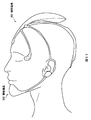
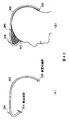
- FIG. 41 is a view schematically showing a hair band in another embodiment and a wearing state thereof.
- FIG. 42 is a view schematically showing a hair band in another embodiment and a wearing state thereof.
- FIG. 43 is a diagram schematically showing the structure of the forehead contact according to another embodiment.
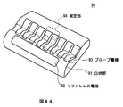
- FIG. 44 is a diagram schematically showing a configuration of a biosignal measurement pillow.
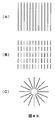
- FIG. 45 schematically shows an arrangement of electrodes in another embodiment.
- FIG. 46 schematically shows the shape of an electrode in another embodiment.
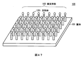
- FIG. 47 is a diagram schematically showing a configuration of a biosignal measurement pillow.
- FIG. 48 schematically shows a structure of a support.
- FIG. 49 schematically shows the sleeping state.
- FIG. 50 is a schematic diagram for explaining the assignment of probe channels.
- FIG. 50 is a schematic diagram for explaining the assignment of probe channels.
- FIG. 51 is a view schematically showing a grounded state of the biosignal measurement pillow.
- FIG. 52 is a diagram schematically showing a configuration of a measurement unit in another embodiment.
- FIG. 53 is a flowchart of an electrode selection process.
- FIG. 54 is a graph showing experimental results.
- FIG. 55 is a graph showing experimental results.
- FIG. 56 is a diagram schematically showing an electrode arrangement at the time of experiment.
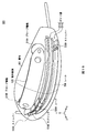
- FIG. 1 shows the configuration of a biological signal measurement device 1.
- the living body signal measurement equipment 1 has a support (hereinafter also referred to as a hair band) 2 that can be supported on the head.
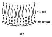
- the teeth of the tooth portion 12A are made of a conductive wire, and from the predetermined position between the center and the root, the tooth tip side is annularly formed, and from the predetermined position, the root sides are wound in opposite directions in contact with each other As a rod, it is fixed to the tooth support bar 12B keeping an equal interval with the adjacent teeth.
- the tooth support bar 12B is a non-flexible conductor thicker than the wire of the tooth portion 12A, and at the other end of the hair band 2, each tooth of the tooth portion 12A in the same direction from the center to the tip of the hair band 2 It is attached so that it points. Further, the tooth support bar 12B is curved toward the non-slip portion 11 of the hair band 2 to an extent that it conforms to the shape on the head side.
- a probe electrode 13 is provided at the center of the hair band 2.
- the probe electrode 13 includes a tooth portion 13A having the same structure as the reference electrode 12 and a tooth support rod 13B.
- the tooth support bar 13B is mounted so that each tooth tip of the tooth portion 13A is directed in the direction perpendicular to the direction from the center to the tip on the surface of the curved top portion of the hair band 2 in the central portion of the hair band 2 Be [1-2. Installation procedure]
- the mounting procedure of the biological signal measurement device 1 will be described.
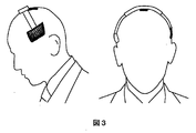
- the back of the hair band 2 is covered until it is in contact between the crown and the forehead. Since the hair band 2 is formed in a resilient C-shape (see FIG.
- the tooth top side is formed in a ring shape with a wire (see FIG. 2).
- each tooth in the hair band 2 is entangled at the base of the hair, and compared to the case of point contact, the degree of adhesion of the teeth to the scalp can be improved and positional deviation can be reduced.
- pain to the subject can be alleviated and the wearing feeling can be improved.
- the hair band 2 in a state of being in contact between the crown and forehead is slid to the crown position.
- the probe electrode 13 provided at the center of the hair band 2 is mounted on the surface of the top of the curved portion of the hair band 2 so that the tips of the teeth 13A face in a direction perpendicular to the direction from the center to the tip. (See Figure 1). Therefore, when the hair band 2 is slid to the top position, teeth can be smoothly inserted into the base of the hair. Further, from the predetermined position between the center and the root of the tooth in the tooth portion 13A, the tooth tip side is formed in a ring shape with a wire (see FIG. 2). For this reason, each tooth in the hair band 2 is entangled at the base of the hair, and the degree of adhesion to the scalp can be improved and positional deviation can be reduced as compared with the case of point contact.
- the root side from a predetermined position between the center and the root is wound in the opposite direction in a mutually contacting state and fixed to the tooth support bar 12B as a bar. (See Figure 2). That is, since each linear tooth is fixed at one point with respect to the tooth support rod 12B, each tooth can be equally moved to the periphery around the fixed point. For this reason, even if force is applied from any direction by turning over etc., it can respond flexibly, and if the force concerned disappears, it can also return to an original state promptly. Therefore, the living body signal measurement equipment 1 can significantly reduce sleep inhibition for the subject.
- the burden on the subject can be reduced without impairing the sense of wearing on the subject.
- the electrodes 12 and 13 in the biological signal measurement equipment 1 are supported by the hair band 2. Therefore, the living body signal measurement equipment 1 can prevent dropping of the electrode at the time of attachment and detachment, and can accommodate the wire connected to the electrodes 12 and 13 inside the hair band 2. As a result, the living body signal measurement equipment 1 can avoid the loss of the electrode at the time of attachment or detachment or entanglement with a cord, and the usability can be improved.
- wearing is an example to the last, and it is not limited to the order of the said mounting
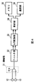
- the measurement unit 30 includes an amplification unit 31, a filter unit 32, an A (Analog) / D (Digital) conversion unit 33, an analysis unit 34, a memory 35, and a communication unit 36.
- the amplification unit 31 has a differential amplifier 31A.
- the differential amplifier 31A amplifies the potential difference between the reference electrode 12 and the probe electrode 13 as a signal (hereinafter, also referred to as a biological waveform signal), and outputs the amplified biological signal to the filter unit 32. Since the probe electrode 13 is an electrode disposed at the top of the head, the biological waveform signal output from the differential amplifier 31A is a signal mainly reflecting an electroencephalogram.
- the reference electrode 12 and the probe electrode 13 have a structure in which the positional deviation is reduced while the adhesion of the teeth 12A and 13A to the scalp is improved. Even if not, the amplification unit 31 can accurately amplify the potential difference in the living body, and as a result, the sensitivity in the measurement unit is improved. Furthermore, the head side position where the reference electrode 12 is positioned and the top position where the probe electrode 13 is positioned are both positions on the skull. Therefore, myoelectric potential components are reduced in the biological waveform signal obtained from the reference electrode 12 and the probe electrode 13, and the sensitivity to the brain wave is improved. In the filter unit 32, a frequency band corresponding to the brain wave is set.
- the filter unit 32 removes a signal component other than the set frequency band from the biological waveform signal, and supplies the removed biological waveform signal to the A / D conversion unit 33.
- it is delta wave (1 to 3 [Hz]), theta wave (4 to 7 [Hz]), alpha wave (8 to 13 [Hz]), beta wave (14 to 30 [Hz]), gamma wave in brain waves
- the analysis unit 34 When the analysis unit 34 receives the measurement start instruction, the analysis unit 34 expands the program stored in the ROM into the RAM, and analyzes the presence or absence of the contact of the electrodes according to the program (hereinafter also referred to as electrode contact detection processing) And waveform analysis processing. An example of the specific processing content of this electrode contact analysis processing will be described.
- the analysis unit 34 compares the average of the levels in the biological waveform data for each defined period with the non-contact level threshold set for the average. If this level average falls below the non-contact level threshold, the analysis unit 34 assumes that the electrode is in non-contact state with respect to the human body surface, stops the processing, and notifies via the speaker that the electrode should be re-mounted. .
- the analysis unit 34 stores the biological waveform data in the specified period in the memory 35 on the assumption that the electrode is in contact with the human body surface.
- the electrode contact analysis process is performed.
- this processing content is just an example.
- the analysis unit 34 recognizes each component of the electroencephalogram waveform, the electro-oculogram waveform and the myo-electric waveform from the biological waveform data.
- the myogenic potential component is reduced in the biological waveform signal.
- the analysis unit 34 determines an awakening time using an electroencephalogram waveform and a myoelectric potential waveform. Specifically, the time when the ⁇ wave appears and the condition where the myoelectric potential appears is taken as the awakening time.
- a plate-like or linear arm 52 (52A, 52B) made of a flexible material such as rubber is attached to the arm 52 by a detachable connecting member.
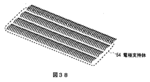
- a plate-like electrode support 54 is connected to the tip of the arm 52.
- snap buttons 53 (53A, 53B) are applied to the connecting member in this embodiment.
- the length of the arm 52 is shorter than the linear distance between the position of the snap button 53 at the position where the hair band 51 is to be attached and the position at which the electrode support 54 is to be attached.
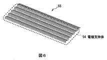
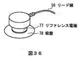
- a probe electrode 55 is provided on one surface of the electrode support 54.
- the probe electrode 55 has a structure in which a plurality of teeth made of a conductive wire are arranged at equal intervals in the row direction and the column direction. The teeth are bent at a predetermined position between the root and the tip, and the tip is rounded.
- the bending angle is a degree obtained by adding several [°] to 90 [°] so that the tooth portion from the tooth tip to the bending position is oblique to the tooth portion from the root to the bending position. As shown in FIG.
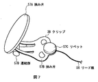
- the reference electrode 57 has a coin-shaped sandwiching piece 57A having the same surface area as the earlobe, a sandwiching piece 57B connected to the sandwiching piece 57A, and a sandwiching piece of the sandwiching piece 57B. It consists of a rivet 57C provided on the surface opposed to 57A.
- the connecting portion 57D of the pinching piece 57A and the pinching piece 57B is movably coupled such that the pinching piece 57A and the pinching piece 57B are separated or approached with the coupling portion 57D as a fulcrum.
- the tip of the lead wire 56 is electrically and mechanically fixed between the rivet 57C and the pinching piece 57B.
- the hair band 51 is worn around the head.
- the electrode support 54 connected to the hair band 51 via the arm 52 is attached to the top of the head. Specifically, the electrode support 54 is placed at the top of the head with the surface having the probe electrode 55 facing the head, and then slid in the same direction as the tip of the tip of the probe electrode 55.
- the arm 52 is made of a flexible material such as rubber, and the arm length is a linear distance between the position of the snap button 53 at the position where the hair band 51 is to be attached and the position where the electrode support 54 is to be attached. It is shorter than that.
- the electrode support 54 when the electrode support 54 is mounted on the top of the head, the electrode support 54 is provided with the force that causes the arm 52 to return to the original arm length as a force that presses the top of the head.
- Probe electrode 55 is closely attached to the scalp.
- a plurality of linear teeth constituting the probe electrode 55 are bent at a predetermined position between the root and the tip, and the tip is rounded (see FIG. 6). Therefore, when the electrode support 54 is slid, the teeth can be smoothly inserted into the base of the hair without the teeth hurting the scalp.
- the slide of the electrode support 54 causes each tooth of the probe electrode 55 to be entangled at the base of the hair.
- the probe electrode 55 can improve the adhesion to the scalp and reduce the positional deviation as compared with the case where non-bent teeth are adopted.
- the head on which the probe electrode 55 is located is a part where contact with the pillow is substantially avoided even in a normal sleep, even if it turns over, the discomfort due to the presence of the probe electrode 55 is reduced and the probe by turning over is also performed. Misalignment of the electrodes 55 can be avoided. Therefore, the biological signal measurement equipment 50 can significantly reduce sleep disturbance for the subject.
- the burden on the subject can be reduced without impairing the sense of wearing on the subject.
- the reference electrode 57 is attached to the earlobe. Specifically, the earlobe is sandwiched between the coin-shaped sandwiching piece 57A and the rivet 57C (see FIG. 7) provided on the sandwiching piece 57B. Since the earlobe is sandwiched between the clip piece 57A and the rivet 57C and the rounded portion, pain to the subject can be alleviated, and as a result, sleep disturbance to the subject can be significantly reduced.
- the biological signal measurement equipment 50 is mounted on the head, the probe electrode 55 is fixed to the scalp, and the reference electrode 57 is fixed to the earlobe.
- the measuring unit in the biological signal measuring equipment 50 is provided, for example, on the surface or inside of the electrode support 54.
- the configuration of the measurement unit is the same as that of the measurement unit in the biological signal measurement equipment 1 and thus will not be described here.
- the probe electrode 55 since the probe electrode 55 has a structure in which positional deviation is reduced while the adhesion of the teeth to the scalp is improved, the measurement unit does not adhere the electrode to the scalp with the paste.
- the potential difference in the living body can be accurately amplified, and as a result, the sensitivity in the measurement unit is improved.
- the top of the head at which the probe electrode 55 is located is a position on the skull.
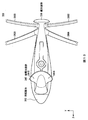
- the biosignal measurement equipment in the third embodiment is configured of a head equipment 300 (FIGS. 9 to 16) and a jaw equipment 500 (FIGS. 19 to 22).
- the head brace 300 has a support (hair band) 310 that can be supported on the head.
- the hair band 310 is a C-shaped plate made of a flexible and rigid plate like plastic or metal. Therefore, regardless of the difference in the shape of the head, it is possible to flexibly fit and hold the state.
- one end hereinafter also referred to as a front end
- a front end is the other end so that one end is visible on the forehead side and the other end is visible on the occipital side.
- the cross section of the hair band 310 is asymmetrical with respect to the vertical line passing through the longitudinal and widthwise centers of the hair band 310, and the length of the hair band 310 from the center to the front end is the center Is shorter than the length of the hair band 310 from the rear end to the rear end.
- the width of the hair band 310 is smaller than the distance between the straight line connecting "F3" and "P3" and the straight line connecting "F4" and "P4" in the international 10-20 method. Specifically, 25 [mm] or less is preferable.
- the hair band 310 can be flexibly fitted to the contour through the midsagittal plane while opening the side of the head.
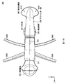
- recesses (dents) 311 and 312 are provided at a central position of the hair band 310 at predetermined intervals (see FIG. 9). This interval is, for example, an average of the distance between the central center of an adult (Cz in the international 10-20 method) and the median parietal region (Pz in the international 10-20 method), and is based on the front end.
- Probe electrodes 320A and 320B are provided in these recesses 311 and 312 (see FIGS. 9 to 11). As shown in FIG.
- the probe electrodes 320A and 320B have a brush structure in which a plurality of conductive fibers 321 are planted on the substrate 322 upright at predetermined intervals in the horizontal and vertical directions.
- the material of the conductive fiber 321 is, for example, carbon, amorphous, stainless steel, or sandalon.
- the thickness (fiber diameter) or thickness of the conductive fiber 321 is set to a degree that does not cause pain to the subject and has a flexible rigidity. In this embodiment, the thickness of the conductive fiber 321 is 25 ⁇ m, and the length of the conductive fiber 321 is 10 mm.
- the substrate 322 is fixed to the bottom of the recess 311, 312.
- the planting area of the conductive fiber 321 and the surface area of the recessed parts 311 and 312 are each set to such an extent that the mobility of the conductive fiber 321 is not impaired.
- the length of the conductive fiber 321 and the depth of the recesses 311 and 312 are such that the tip of the conductive fiber 321 protrudes from the inner surface of the hair band 310 to the extent that the fit of the hair band 310 with the head is not impaired. It is set.
- a plurality of grooves 313 are formed at predetermined intervals in the longitudinal direction of the hair band 310 between the recess 312 and the rear end of the hair band 310 (see FIG. 9).
- an adjuster portion 330 which can slide in the longitudinal direction of the hair band 310 with the portion as a core is provided (see FIGS. 9 to 11 and FIGS. 14 to 16).
- a claw (not shown) that can be fitted to the groove 313 is provided in a portion of the inner surface of the adjuster portion 330 facing the groove 313 of the hair band 310, and the total length of the hair band 310 can be adjusted stepwise It has become. Therefore, the attachment of the hair band 310 can be enhanced according to the size and shape of the head.
- the claw is engaged with the total length of the hair band 310 and the furthest groove 313B (FIG.
- the open end of the adjuster 330 can be arranged to avoid contact of the tip of the adjuster 330 with the protruding portion of the head, pain during sleep for the subject is alleviated, resulting in sleep disturbance for the subject. It is greatly reduced.
- the width from the position from the concave portion 312 to the rear end side by a predetermined distance from the rear end to the rear end is narrower than the width from the position to the front end (see FIG. 18), and
- the portion is a stopper for the adjuster portion 330. Therefore, the number of parts can be reduced as compared with the case where a separate stopper is provided, and the size can be reduced accordingly.
- the core region 340A in the center and its vicinity is made of a hard material
- the peripheral region 340B other than the core region 340A is made of a soft material such as silicon or urethane (see FIG. 18). Therefore, the adhesion to the head is enhanced, and biting into the head is suppressed.
- a hair fastener (not shown) or a suction cup (not shown) is detachably attached to the inner surface side of the core region 340A through the perforation holes 341A, 341B. Therefore, the stability to the head can be further enhanced with or without hair.
- this core area 340A is in a state of being recessed to the height of the hair clamp or the suction cup as compared with the peripheral area 340B. Therefore, the condition in which the occipital contact portion 340 floats from the head due to the attachment of the hair clip or the suction cup is avoided in advance.
- the connection portion between the core region 340A and the adjuster portion 330 is provided with an angle adjusting mechanism 342 for changing the angle of the inner surface of the occipital contact portion 340 with respect to the inner surface of the hair band 310. Accordingly, it is possible to adjust the angle of the inner surface of the occipital contact portion 340 with respect to the contact portion of the head, and as a result, the stability to the head is further enhanced.
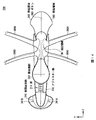
- a portion (hereinafter, also referred to as a forehead contact portion) 350 that is in contact with the forehead is attached (see FIGS. 9 to 16).
- the forehead contact portion 350 has a teardrop shape, and is made of a soft material such as silicon or urethane. Therefore, closeness to the forehead is enhanced, and bite into the forehead is suppressed.
- a concave groove 351 is formed which divides the inner surface into an upper region and a lower region (see FIGS. 9 to 11, 15 and 16). The concave groove 351 improves the flexibility of the forehead contact portion 350, and as a result, the adhesion of the forehead contact portion 350 to the forehead is further enhanced.
- the protruding area 362 is separated from the hair band 310 and protrudes upward at a predetermined distance from the top outer surface of the hair band 310.
- the substrates are spaced apart to allow for head attachment. That is, it is possible to smoothly wear the hair band 310 without preventing a change in the bending state when the hair band 310 is worn.
- the shape of the projection region 362 is flat and gentle as compared with the hair band 310. Therefore, the selection width of the circuit board can be expanded as compared with the case where the electronic device is housed inside the hair band 310, and the influence of the bending of the hair band 310 can be avoided.
- the arms 380C and 380D have a length enough to reach a recess (hereinafter also referred to as a temple) surrounded by the frontal bone, zygomatic arch and zygomatic orbital process, and attach the probe electrodes 400A and 400B to the temples at their tips.
- Parts (hereinafter also referred to as temple attachment parts) 410A, 410B are provided (see FIGS. 9 to 11).
- Each arm 380 is formed of a soft material such as silicon, PBT or PP and formed in a cylindrical shape. Inside each arm 380, a rigid linear member (not shown) such as a piano wire or a wire is attached. Therefore, the shape of the arm 380 can be flexibly adjusted and the state after the adjustment can be maintained.
- the earlobe attachment portions 390A, 390B (FIGS. 9 to 11) have frames 391A, 391B connected to the tips of the arms 380A, 380B, and jacks 392 A 392B is provided.
- the frame bodies 391A and 391B are structured such that the magnetic reference electrodes 370A and 370B are exposed in the central area except the whole of the plane area of the frame bodies 391A and 391B or the edges.
- disk-shaped magnets 394A and 394B are attached to the frames 391A and 391B via flexible plate-shaped connecting members 393A and 393B.
- the earlobe attachment portions 390A and 390B bend the connecting members 393A and 393B, sandwich the earlobe between the magnets 394A and 394B and the reference electrodes 370A and 370B, and fix the reference electrodes 370A and 370B to the earlobe by magnetic force. It can be done.
- the temple attachment portions 410A, 410B (FIG. 9) have frame bodies 411A, 411B connected to the tips of the arms 380A, 380B, and in the central area excluding the entire flat area of the frame bodies 411A, 411B or the edge. , And the probe electrodes 400A and 400B are exposed.
- different shapes are assigned to the frame bodies 391A, 391B, 411A, and 411B so that “upper right”, “upper left”, “lower right”, and “lower left” can be visually recognized.
- a lead (not shown) is connected to each reference electrode 370 and each probe electrode 400, and the lead is along a linear member (not shown) disposed inside the corresponding arm 380, It is drawn out to the inside of fixed field 361 in projection case 360.
- a lead wire (not shown) is also connected to each probe electrode 320 attached to the hair band 310, and the lead wire is drawn out to the inside of the fixing region 361 in the projection housing 360 via the inside of the hair band 310.
- the amplifiers (not shown) assigned to the electrodes 320, 370 and 400 are connected, and the ground lines of these amplifiers are connected to one ground point respectively. This is a grounding method called star type ground.
- the position where the fixed region 361 is disposed is a position where the electrodes 320, 370, and 400 have the shortest distance with respect to the position. For this reason, the disturbance noise superimposed on the lead wire with respect to these electrodes 320, 370, and 400 is reduced significantly.
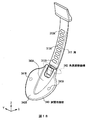
- the jaw device 500 has a housing 501 formed by combining a soft raw material and a rigid material, and the housing 501 has a surface corresponding to the shape of the man in the mandible (hereinafter referred to as “this”) Is also referred to as a ridge-facing surface)) 502.
- a tacky sheet such as a solid gel is attached to the guy raised facing surface 502. Therefore, even if the mirror or the like does not look at it, it is possible to easily fit it in a groin by the shape of the protuberance facing surface 502, so that the fitted state can be stabilized.
- the probe electrodes 510A and 510B, the electronic substrate 520, and the rail 530 are mounted inside the housing 501.
- the probe electrodes 510A, 510B have a disk shape, and are disposed, for example, at positions perpendicular to the chin of the chin.
- the electronic substrate 520 is a flexible substrate, and is disposed between one of the probe electrodes 510A and the other of the probe electrodes 510B in a curved shape along the guy raised facing surface 502.
- the electronic substrate 520 is provided with an amplifier (not shown) for amplifying the biological signal sensed by the probe electrodes 510A and 510B.
- the rail 530 is made of a material having high slidability such as POM, and is horizontally disposed in a state of presenting a curve along the guy raised facing surface 502.
- An upper stage guide groove 531A and a lower stage guide groove 531B are formed in the rail 530.
- a pile-like stopper 532A is fixed to one end of the upper guide groove 531A, and one end of a spring 533A that expands and contracts along the track of the upper guide groove 531A is fixed to the stopper 532A.
- One end of an arm 534A inserted into the upper guide groove 531A is fixed to the other end of the spring 533A.
- the other end of the arm 534A is provided with a pin type connector (not shown) corresponding to the connector 392 of the earlobe attachment portion 390A, and is attached to and detached from the connector 392.
- a pile-like stopper 532B is fixed to one end of the lower guide groove 531B. This one end is an end located on the side opposite to the one where the stopper 532A is provided in the upper stage guide groove 531A.
- one end of a spring (not shown) is fixed to the stopper 532B, and one end of an arm (not shown) is fixed to the other end of the spring (not shown) .
- the other end of the arm is provided with a pin type connector (not shown) corresponding to the connector 392 of the earlobe attachment portion 390B, and is attached to and detached from the connector 392.
- the springs 533A, 533B adjust the arms 534A, 534B to a length corresponding to the distance between the jaw brace 500 and the earlobe attachment portion 390A, and give mutually opposing pressing forces to the jaw brace 500.
- the arms 534A and 534B are made of a soft material such as silicon, PBT or PP and are formed in a cylindrical shape. Inside the arms 534A, 534B, rigid linear members (not shown) such as piano wires or wires are attached. Therefore, it becomes possible to arrange arms 534A, 534B along the face on the mandibular angle portion and to maintain the adjusted state. Further, the stoppers 532A and 532B adjust their fixing positions by changing the fitting destination with respect to the plurality of fitting portions 535 (see FIG. 20) formed at predetermined intervals in the track direction of the upper stage guide grooves 531A and 531B. It can be done. [3-2.
- the hair band 310 is placed in the front-rear direction of the head. Since the front end portion of the hair band 310 is formed at a position higher than the rear end portion (see FIGS. 10 and 11), the subject can intuitively grasp the front-rear direction of the head brace 300. Further, the hair band 310 is a plate material having flexibility and rigidity like plastic or metal, and the width thereof is a straight line connecting “F3” and “P3” in the international 10-20 method, “F4” and “P4”.
- the hair band 310 fits softly against the contour through the mid-sagittal plane while opening the lateral part of the head, resulting in migraine and discomfort caused by the subject lying down. It is greatly eased.
- the hair band 310 has a structure in which the fore-and-aft direction of the head is sandwiched through the outline portion passing through the midline sagittal plane, the weight of the hairband 310 squeezes the outline portion passing through the midline sagittal plane become.
- nerve groups, blood vessel groups, and lymph groups extending from head to head do not intervene in the portion in contact with the inner surface of hair band 310 (outline portion passing through the mid-sagittal plane) .
- muscles extending from the face to the head also do not intervene in the portion in contact with the inner surface of the hair band 310 (outline portion passing through the median sagittal plane). Therefore, for example, as in the first embodiment, the hair band 310 for nerve, vasculature, lymphatic system, and muscle system as compared with the structure in which the head is sandwiched without passing the contour through the midline sagittal plane. The amount of pressure on the body is minimized.
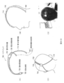
- FIG. 23 is [online], “Facial Nerves” free encyclopedia Wikipedia, [May 27, 2010 search], Internet ⁇ URL: http: // ja. wikipedia. org / wiki /% E9% A1% 94% E9% 9D% A2% E7% A5% 9E% E7% B5% 8C>.
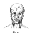
- 24 and 25 show F.I. H. It is described in Martini, "Color human anatomical chart", Nishimura Shoten, 2003, published on page 8.
- FIG. 26 and FIG. 27 are described in Yoshikuni Kawai, “Meat Only”, published by NTS, June 8, 2007, 26th issue, page 7-8.
- the tips of the probe electrodes 320A and 320B project to such an extent that the fit of the hair band 310 with the head is not impaired.
- the degree of adhesion of the In general, since the scalp has more sebum secretion and faster metabolism than skin with a relatively small amount of hair such as the face, the stratum corneum tends to form. Therefore, it is necessary to wash the scalp before the electrode is attached in the conventional electroencephalogram measurement.
- the probe electrodes 320A and 320B have a structure in which a plurality of conductive fibers 321 are planted in an upright state with respect to the substrate 322, all or part of the conductive fibers 321 avoid hair and sebum and keratin It penetrates the layer and contacts the scalp. Therefore, it is possible to measure the electroencephalogram even if the cleaning of the electrode scalp is omitted, and as a result, it is possible to reduce the burden on the subject without substantially deteriorating the measurement accuracy and to perform the long-term electroencephalogram measurement. Become.
- application of a paste is necessary to maintain the contact of the electrode to the scalp.
- the brush-structured electrode prototyped probe electrode 320
- the same result as in the prior art is obtained where sensing is performed with a conventional paste-applied dish electrode .
- fine adjustment of the position of the occipital contact portion 340 with respect to the head is performed. That is, the length of the hair band 310 is adjusted by the adjuster portion 330 so that the occipital contact portion 340 is positioned immediately above the occipital center (Oz in the international 10-20 method).
- the occipital contact portion 340 is disposed avoiding contact with the protruding portion of the head, pain during sleep for the subject is alleviated and as a result, sleep disturbance for the subject is significantly reduced. Further, the angle of the occipital contact portion 340 is adjusted by the angle adjustment mechanism 342 (FIG. 18) such that the inner surface of the occipital contact portion 340 is substantially parallel to the contact surface of the head. Therefore, the stability to the head is enhanced.
- a hair clip (not shown) or a suction cup (not shown) detachably attached to the occipital contact portion 340 is attached to the hair or scalp. Therefore, the stability to the head can be further enhanced with or without hair.
- the shape of the arms 380A and 380B is appropriately changed so that the tip is located at the earlobe along the head surface via the back of the ear, and the arm 380C so that the tip is located at the temple along the face surface,
- the shape of 380D is suitably changed.
- Each arm 380 is formed of a soft material in a cylindrical shape, and a rigid linear member (not shown) is attached to the inside thereof, so that the shape of the arm 380 can be flexibly adjusted to the subject. And can maintain its adjusted state.
- the earlobe attachment portions 390A, 390B provided at the tip of the arms 380A, 380B are attached to the earlobe, and temple attachment portions 410A, 410B provided at the tip of the arm C, 380D are attached to the temple.
- the earlobe attachment portions 390A and 390B have a structure in which the earlobe is sandwiched between the magnets 394A and 394B and the reference electrodes 370A and 370B. Therefore, stability and adhesion of the reference electrodes 370A and 370B to the earlobe can be secured. In addition, it becomes possible to quickly fix the reference electrodes 370A and 370B to the subject.
- the temple attachment parts 410A and 410B attach a sheet having adhesiveness to the skin to the edge of the frame 411A and 411B, stability and adhesion of the probe electrodes 400A and 400B to temples can be secured. . In addition, it becomes possible to quickly fix the reference electrodes 370A and 370B to the subject.
- the casing 501 is put on the jaws.
- the housing 501 is formed with a surface (a surface facing the top of the man) that corresponds to the shape of the man in the mandible.
- the arms 534A, 534B are stretched, and the shapes of the arms 380A, 380B are appropriately changed so as to be along the face on the mandibular angle portion.
- the arms 534A and 534B are made of a soft material and formed in a cylindrical shape, and a rigid linear member (not shown) is attached to the inside thereof, so that the shape of the arm 534 can be flexibly adjusted to the subject And can maintain its adjusted state.
- the pin connector at the tip of the arms 534A, 534B is inserted into the jack connector of the arm earlobe attachment portion 390A.
- the arm 534 is connected via a spring 533 to a stopper 532 fixed to the side opposite to the left and right of the arm 534 in the guide groove 531 of the rail 530.
- the arm 534 is adjusted by the spring 533 to a length corresponding to the distance between the jaw brace 500 and the earlobe attachment portion 390A, and the jaw brace 500 is displaced by the mutually opposing pressing forces of the spring 533. Is prevented and stabilized.
- the head brace 300 and the jaw brace 500 are attached to the head and the jaw.
- the probe electrodes 320A and 320B are fixed to the scalp, the probe electrodes 400A and 400B to the temples, the reference electrodes 370A and 370B to the earlobe, and the probe electrodes 510A and 510B to the humps.
- the order of attachment described above is merely an example, and is not limited to the order of attachment.
- the measurement unit 600 includes an amplification unit 631, an A / D conversion unit 33, a filter unit 632, an operation unit 650, an analysis unit 634, a memory 35, and a communication unit 36.
- the amplification unit 631 has amplifiers 631A to 631F assigned to the electrodes 320, 370, and 400, and amplifies the difference between the electrodes 320, 370, and 400 and the reference potential (ground point).
- the filter unit 632 is not different from the filter unit 32 which is an analog filter in that it is a digital filter.
- the filter unit 632 has filter units 632A to 632F assigned to the respective electrodes 320, 370, and 400, removes signal components other than the set frequency band, and then removes the corresponding A / D conversion units 33A to 33F.
- the conversion result of is obtained.
- a band pass filter for selecting a frequency band of brain waves, a notch filter for removing AC noise, or a combination thereof is preferable.
- the position where the fixed region 361 in the projection housing 360 is disposed is a position where the respective electrodes 320, 370, 400 have the shortest distance with respect to the position, and the electrodes 320, 370, 400 are disposed.
- the ground lines of the amplifier assigned to are concentrated at one point in the fixed area 361. For this reason, even if there is no shield room, the influence of noise is greatly reduced, and as a result, even in a home, it is possible to measure brain waves. By the way, when an electroencephalogram measurement becomes possible in a home, various disturbance noises exist.
- a typical example is noise from an outlet.
- the frequency band of the noise generated from the outlet differs depending on the area, such as Tokyo and Kansai
- the frequency band to be removed by the filter unit 632 is different.
- the analog filter shown in FIG. 4 it is difficult to switch the frequency band to be removed by one filter, so filters of the number of frequency bands to be removed are required.
- the filter unit 632 in the measurement unit 600 is a digital filter, it can be included in the operation unit 650, and switching of the frequency band to be removed etc. is performed using one DSP capable of pipeline processing. It can be implemented by programming.
- the filter unit 632 can accurately remove the frequency band considered as disturbance noise with the minimum number of solids, and as a result, improve the measurement accuracy.
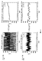
- FIG. 33 An experimental result is shown in FIG.
- the upper part of this FIG. 33 is a case where it measures outside a shield room using the cable length (1.5 [m]) equivalent to the cable length in the conventional electroencephalogram measurement. In this case, the AC signal saturates the biosignal, and the biosignal is buried in the noise even if the notch filter is applied.
- the AC noise has an amplitude similar to that of the biological signal, and the biological signal appears by applying a notch filter.
- the distance between the probe electrodes 510A and 510B in the jaw brace 500 and the fixation region 361 is longer than that of the other electrodes 320, 370, and 400. Therefore, in the jaw brace 500 separately from the fixation regions 361. Connected to the amplifier. Therefore, the influence of noise on the biological signal sensed by the probe electrodes 510A and 510B does not substantially cause a problem.
- the computing unit 650 takes the difference between the output of the filter units 632A and 632B assigned to the probe electrode 320 and the output of the filter unit 632A or 632B assigned to the reference electrode 370, and outputs the result to the subsequent stage. Further, the computing unit 650 takes the difference between the outputs of the filter units 632 E and 632 F assigned to the probe electrode 400 and the outputs of the filter units 632 A and 632 B assigned to the reference electrode 370 and outputs the result to the subsequent stage. In addition, in the operation unit 650, in the electronic circuit 520 disposed in the case 501 of the jaw device 500, the difference between the probe electrodes 510A and 510B and the reference potential (ground point) is amplified and subjected to the filtering process.
- the analysis unit 634 determines the start time, end time, and quality of REM sleep using the myoelectric potentials of the jaws sensed by the probe electrodes 510A, 510B in addition to the myoelectric potentials of the eyes sensed by the probe electrodes 400A, 400B. Do. Generally, it is known that during REM sleep, the muscle strength of the jaw weakens as compared to that during REM sleep.
- the determination accuracy is further improved as compared with the analysis unit 34 that determines the start time, the end time, and the quality of REM sleep only by the myoelectric potentials of the eyes sensed by the probe electrodes 400A and 400B.
- the hair bands 2 are attached so as to sandwich the left and right sides of the head.
- the mounting method is not limited to this.
- the hair band 2 may be worn so as to sandwich the front and back sides of the head.
- the hair band 2, the reference electrode 12 and the probe electrode 13 are applied as components of the biological signal measurement equipment 1.
- the components of the biological signal measurement device 1 are not limited to the shapes, structures, and the like shown in the above-described embodiment.
- a support assisting portion 61 which has a gentler bend than the bend of the hair band 2 and is shorter than the entire length of the hair band 2 is attached to the curved top portion of the hair band 2,
- the biological signal measurement equipment 60 connected in the direction orthogonal to the hair band 2 is applicable. Since the hair band 2 of the living body signal measurement equipment 60 sandwiches the front and back sides of the head in the same manner as the hair band 310 of the head equipment 300, the structure thereof is for living body signal measurement which sandwiches the left and right sides of the head.
- the hair band 2 of the appliance 1 has a similar but different shape.
- the hair band 2 of the biological signal measuring device 1 is symmetrical (symmetrically) on the basis of the position having the largest curvature to be brought into contact with the crown, and each of the positions from the position to each end The lengths of are generally the same. Further, the height positions of both ends of the hair band 2 at the time of wearing are substantially the same.
- the hair band 2 of the living body signal measurement equipment 60 is asymmetric (back and forth asymmetry) on the basis of the position having the largest curvature to be abutted against the crown, like the hair band 310 of the head equipment 300. The length from the position to the front end is shorter than the length from the position to the rear end.
- the height positions of both ends of the hair band 2 at the time of wearing have a positional relationship in which the reference electrode 12 which is the occipital contact portion is lower than the non-slip portion 11 which is the forehead contact portion.
- the length of the supporting auxiliary portion 61 is set to such an extent that the end portion of the supporting auxiliary portion 61 is located at "C3" and "C4" in the international 10-20 method.
- the head can be supported by sandwiching, and the positional deviation of the electrodes 12 and 13 with respect to the scalp can be reduced as compared with the biological signal measurement device 1.
- the width of the hair band 2 of the living body signal measurement equipment 60 is smaller than the distance between “C3” and “C4” in the international 10-20 method, and the length of the support auxiliary portion 61 is It is said that the distance is about. Therefore, with this biosignal measurement equipment 60, migraine headaches and discomfort caused by the subject lying down are greatly alleviated, and the amount of compression on nerves, blood vessels, lymphatics, muscle systems is minimized. Migraine headaches and discomfort caused by wearing are also greatly alleviated.
- the degree of entanglement of each tooth with the base of the hair increases compared to the reference electrode 12 or the probe electrode 13. Therefore, the positional deviation can be further reduced while the adhesion of the tooth to the scalp is further improved. it can.
- the tooth support rods 12B and 13B of the reference electrode 12 and the probe electrode 13 are omitted, and the teeth 12A and 13A of the reference electrode 12 and the probe electrode 13 are directly fixed to the inner surface of the hair band 2.
- the reference electrode 57 is attached to the earlobe.
- the mounting position of the reference electrode 57 is not limited to this embodiment.
- the upper pinnacle and the temple position can be set as the mounting position.
- the hair band 51, the arm 52, the snap button 53, the electrode support 54, the reference electrode 55, and the probe electrode 57 are applied as components of the living body signal measurement equipment 50.
- the components of the living body signal measurement equipment 50 are not limited to the shapes, structures, and the like shown in the above-described embodiment.
- the electrode structure which attached the tube to the electrode of a gulf-like like the electrode used by an electrocardiogram.
- an electrode structure other than a sucker structure may be applied.
- a mode in which one of the arms 52A and 52B and the snap buttons 53A and 53B is deleted is applicable.
- the components of the living body signal measurement equipment 50 are not limited to the shapes, structures, etc. shown in the above-described embodiment other than the examples described above, and can be changed without departing from the object of the present invention It is.
- the form which combined suitably the component of the biological signal measurement apparatus 1 in the above-mentioned 1st Embodiment, and the component of the biological signal measurement apparatus 50 in 2nd Embodiment is applicable.
- the reference electrode 12 provided at the other end of the hair band 2 is changed to the non-slip portion 11, and the reference electrode 57 is provided at the tip of the lead wire 56 drawn from the inside of the hair band 2.
- a probe electrode 55 is provided instead of the probe electrode 13.
- FIG. 38 a portion (twisted portion (see FIG. 2)) of the teeth of the probe electrode 13 which is formed as a rod is diagonally opposed to the surface of the electrode support 54 The root is fixed, and the portion formed as an annular shape (see FIG. 2) is in a state of facing in parallel to the surface. In this way, the contact area to the scalp can be increased.
- the electrode support 54 is mounted on the top of the head, the force of the arm 52 to return to the original arm length on the surface of the electrode support 54 facing the head is the force that holds the top of the head. Since the force of returning the annular portion of the probe electrode shown in FIG.
- the probe electrodes 320A and 320B have a brush structure.
- the structure of the probe electrode is not limited to this embodiment.
- the adjuster portion 330 is provided between the concave portion 312 and the rear end portion of the hair band 310.
- the installation location of the adjuster portion 330 in the hair band 310 is not limited to this embodiment.
- it can be provided between the recess 311 and the recess 312 or between the recess 311 and the fixing area 361 in the projection housing 360.
- the adjuster portion 330 may be omitted from the hair band 310.
- the slide type adjuster portion 330 is provided.
- the hair band 310 itself is made of a stretchable material, and a rigid frame is provided on the side of the hair band 310 so that the length of the hair band 310 itself can be adjusted in the longitudinal direction. It is also good.
- the button 363 is provided on the upper surface of the projection area 362, and the connector 364 is provided on the side surface of the projection area 362.
- the installation places of the button 363 and the connector 364 are not limited to this embodiment, and various places can be applied.
- the button 363 of a type in which the power is turned on or off by pressing for a few seconds is adopted.
- the type of turning the power on or off is not limited to this embodiment.
- it can be a slide type.
- a button of a type in which the power is turned on or off instantaneously by a pressing operation may be provided in a recessed state relative to the upper surface of the projection area 362.
- a touch sensor may be provided.
- the lengths of the arms 380 and 534 are fixed.
- a slide type adjuster may be provided, and the arms 380 and 534 themselves may be capable of adjusting the length in the longitudinal direction.
- the amplification unit 631 that amplifies the difference between each of the electrodes 320, 370, and 400 and the ground point shared by the amplification unit 631 is employed.
- the ear reference electrodes 370A and 370B may be used as a reference for the entire measurement unit. Even in this case, it has been confirmed that the measurement sensitivity has been obtained to such an extent that the measurement becomes substantially impossible.
- the components of the head brace 300 and the jaw brace 500 are not limited to the shape, structure, and the like shown in the above-described third embodiment, and the object of the present invention It can be changed in the range which does not deviate.
- the electrode is pressed directly against the surface of the human body, but to efficiently transmit the wave to the electrode, such as water, alcohol, oil or glycerin.
- a couplant may be applied.
- it is good also as a structure provided with the mechanism which pours a contact medium to an electrode.
- a container for storing the contact medium in the hair band 2, the electrode support 54, and the projection area 362 is provided, and a needle-like tube material for flowing the contact medium to the electrode is connected to the valve provided in the container
- the tip of the tube can be arranged at one end of the electrode.
- the measurement target is an electroencephalogram, but body temperature or a pulse can also be added.
- a body temperature sensor or a pulse sensor of, for example, an optical system is provided to the biological signal measurement device 1, 50, the head device 300, or the jaw device 500, and a signal supplied from the sensor is an A / D converter 33 to the analysis unit 34.
- the analysis unit 34 stores body temperature data or pulse data in the memory 35 in association with brain wave data. Such association can be used as an index for identifying sleep disorders and diseases.
- the support (hair band) supported on the head by sandwiching in the back and forth direction of the head with the portion to be abutted to the forehead and the portion to be abutted to the occipital end is a biological signal measuring device
- the hair bands 2 of 60, and the hair bands 310 of the head brace 300 are not limited.
- the hair band 600 shown in FIG. 39 is applicable.
- stoppers made of resin such as rubber are fitted to form a forehead contact portion 610 and an occipital contact portion 620.
- the hair band 600 is formed of a C-shaped tube-like plastic or metal material (hereinafter, also referred to as a wire-like tube material) whose cross section is hollow or a true circle or an ellipse. Specifically, it is asymmetric (back and forth asymmetry) based on the position of the largest curvature to be abutted on the top of the head, and the length from the position to the front end is greater than the length from the position to the rear end Too short. Further, the height positions of both ends of the hair band 600 at the time of wearing have a positional relationship in which the occipital contact portion 620 on the rear side is lower than the forehead contact portion 610 on the front side.
- the hair band 600 can be flexibly fitted regardless of the difference in the shape of the head, and the state can be maintained.
- the width of the hair band 600 is smaller than the distance between the straight line connecting "F3" and "P3" in the international 10-20 method and the straight line connecting "F4" and "P4", preferably It is said that it is 25 mm or less. Therefore, the hair band 600 significantly reduces migraine headaches and discomfort caused by the subject lying down, and minimizes the amount of pressure applied to nerves, blood vessels, lymphatics, and muscle systems, resulting in migraines caused by wearing. And discomfort is also alleviated significantly.
- a hair band 700 shown in FIG. 40 is applicable.
- the center of one wire-like tube is bent and a tube portion (hereinafter, also referred to as a first tube portion) 710 from the bent end to one open end is opened, and the other is opened.
- a tube portion up to the end (hereinafter, also referred to as a second tube portion) 720 is formed.
- the first pipe section 710 and the second pipe section 720 are formed in the same C-shape, respectively, and are members holding a pair of pipes in a parallel relationship at mid positions at the same distance from the open ends ( Hereinafter, it is also referred to as a tube holding portion) 730, 740 are attached.
- the first pipe section 710 and the second pipe section 720 are in contact with the forehead by the pipe holding section 730 from the bent end to the first halfway position near the bent end Portion 750).
- the pipe material holding portion 740 makes a parallel state like a rail from the first midway position to the second midway position, and branches in directions away from each other with the second midway position as a branch position.
- This branch position (the second midway position) is later than the position corresponding to the center of the head (the "Cz" position of the international 10-20 method) of the first pipe section 710 and the second pipe section 720. (Occipital side) is considered closer.
- the curvature of the frontal bone and the curvature of the parietal bone may differ, and the first and second pipe members 710 and 720 Among them, the part from the branch position to the open end may float from the occipital surface or the like. Therefore, by setting the branch position behind (open end) the center position of the head, the first tube portion 710 and the first pipe portion 710 are compared to when the center position of the head is located forward (folded end). The amount of fitting to the occipital region from the bifurcated position to the open end in the second tube portion 720 is improved.
- portions (hereinafter also referred to as raised inclined abutments) 760, 770 that are in contact with the neck-side inclined portion of the external occipital ridge It is formed.
- the raised inclined abutments 760, 770 are inclined inward relative to the first tubular portion 710 and the second tubular portion 720 near the raised inclined abutments 760, 770. Therefore, at the time of wearing, the raised inclined abutments 760 and 770 are caught by the neck-side inclined portion of the external occipital ridge and the pinched state with the forehead abutment 750 is maintained.
- the support for the head is strengthened as compared with the case where the raised inclined abutments 760 and 770 are not bent inward relative to the first tube portion 710 and the second tube portion 720 in the vicinity thereof.
- a stopper made of resin such as rubber is fitted into the raised inclined abutment portions 760, 770. This further strengthens the support for the head.
- the head can be supported by sandwiching the fore-and-aft direction of the head at three points of one point on the head and two points on the neck side inclined portion of the external occipital ridge As compared with the hair band 600, the displacement of the electrode relative to the scalp can be reduced.
- the width of the portion of the first pipe section 710 and the second pipe section 720 aligned in parallel from the first midway position to the second midway position is “C3” in the international 10-20 method and “ C4 "is made smaller than the distance between them.
- the width from the bifurcation position to the neck side inclined part of the external occipital ridge becomes narrower than the width. Therefore, with this hair band 700, migraine headaches and discomfort caused by the subject lying down are greatly alleviated, and the amount of pressure applied to nerves, blood vessels, lymphatics and muscles is suppressed, and migraines caused by wearing do not occur. Pleasure is also alleviated significantly.
- a hair band 800 shown in FIG. 41 is applicable.
- three sheet materials 810, 820, and 830 made of a water-curable resin having a predetermined width exhibit a curve with reference to a portion to be abutted at a position near the back of the head than the center position of the head. It is connected in the state of
- the forehead contact portion 840 is attached to the front end of the sheet material 810
- the raised inclined contact portion 850 is attached to the front end of the sheet material 820
- the raised inclined contact portion 860 is attached to the front end of the sheet material 830.
- the connection portion JP of the three reference sheet materials 810, 820, 830 of the hair band 800 is a portion that should be abutted at the occipital position rather than the forehead position than the center position of the head. .
- the amount of fit to the occipital region from the joint portion JP to the raised inclined abutment portions 850, 860 is improved as compared to the case where the forehead position is closer to the forehead than the center position. Further, in the sheet members 820 and 830 to which the raised inclined contact portions 850 and 860 are attached, the raised inclined contact from the vicinity of the center from the area AR1 from the vicinity of the center in the length direction of the sheet members 820 and 830 to the connecting portion JP. The area AR2 up to the parts 850 and 860 is inside.
- the raised inclined abutments 850 and 860 are caught on the neck-side inclined portion of the external occipital ridge and the pinched state with the forehead abutting unit 840 is maintained.
- the region AR2 from the vicinity of the center to the raised inclined abutments 850 and 860 is fitted as compared with the case where it is not inserted inside the region AR1 from the vicinity of the center to the connection portion JP, and the support for the head is Be strengthened.
- this hair band 800 When this hair band 800 is applied, as in the case where the hair band 700 is applied, the fore-and-aft direction of the head is three points: one point on the forehead and two points on the neck side inclined portion of the external occipital ridge Because the head can be supported by sandwiching, displacement of the electrode relative to the scalp is reduced. Also, the width of the sheet material is made smaller than the distance between "C3" and "C4" in the International 10-20 method. Therefore, in this hair band 800, like the hair band 700, migraine headaches and discomfort caused by the subject lying down are significantly alleviated, and the amount of compression on nerves, blood vessels, lymphatics and muscles is suppressed. Migraine headaches and discomfort caused by wearing are also greatly alleviated.
- the hair band 800 is formed of a water-curable resin, it can be disposable, which is advantageous in terms of cost reduction and ease of handling.
- a hair band 900 shown in FIG. 42 is applicable. At both ends of the hair band 900, stoppers made of resin such as rubber are fitted to form a forehead contact portion 910 and an occipital contact portion 920.
- the hair band 900 is formed in a shape of a wire-like tube. That is, the hair band 900 is asymmetrical (back and forth asymmetry) on the basis of the position to be abutted on the top of the head, and the occipital abutment portion 920 has a lower positional relationship than the forehead abutment 910 at the time of wearing.
- this hair band 900 linearly extends from the position to be abutted on the head to the forehead contact portion 910 and sharps inward (to the occipital contact portion 920 side) in the portion CRP near the contact point with the forehead contact 910 It will be in the state of bending. This point is different from the hair band 600 which is curved along the shape of the head from the position to be abutted to the crown to the forehead abutment 610.
- the portion in contact with the head at the time of wearing is two points of the forehead and the occipital region, and a part of the outline passing through the central sagittal plane (the gap OPG in front of the head as shown in FIG. Except for the part).
- the pressure on the head due to its own weight is reduced as compared with the hair band 2 or the hair band 600 of the living body signal measurement equipment 60.
- migraines and discomfort caused by wearing can be further alleviated.
- the width of the hair band 900 is smaller than the distance between the straight line connecting "F3" and "P3" in the international 10-20 method and the straight line connecting "F4" and "P4", preferably It is said that it is 25 mm or less. Therefore, the hair band 900 significantly alleviates migraine headaches and discomfort caused by the subject lying down, and minimizes the amount of pressure on nerves, blood vessels, lymphatics, and muscle systems, resulting in migraine headaches caused by wearing. And discomfort is also alleviated significantly.
- a structure of a portion of the hair band 2, 600, 700, 800 or 900 which is in contact with the forehead one shown in FIG. 43 is applicable.
- the tip of the hair band 2, 600, 700, 800 or 900 and the plate material (hereinafter also referred to as a forehead contact plate) 1000 to be abutted on the forehead are connected by the ball joint BJT.
- the ball joint BJT includes a ball-shaped convex stud and a concave stud slidably fitted to the ball portion of the convex stud, and these include hair bands (2, 600, 700, 800 or It is fixed to either of the tip of 900) or the forehead contact plate 1000.
- a mesh-like member (hereinafter referred to as adhesive net) 1010 having adhesiveness is attached.
- This adhesive net 1010 has an area larger than the faces F1 and F2 of the forehead contact plate 1000, and the area (the shaded portion in FIG. 43B) other than the area attached to the face F2 should be attached to the forehead An area (hereinafter, this is also referred to as a forehead attachment area) PAR. That is, the portion (surface F1) to be abutted against the forehead and the portion to be attached (the forehead attachment area PAR) are separated separately, and the surface F1 is covered from the back side and attached to the forehead It is supposed to be attached.
- the forehead contact plate 1000 is connected to the hair band (2, 600, 700, 800 or 900) through a movable portion (ball joint BJT). Therefore, the force applied to the forehead contact plate 1000 or the adhesive net 1010 due to the change on the forehead surface is absorbed in the ball joint BJT.
- the forehead contact plate 1000 may be used as an electrode, and the presence or absence of contact of the forehead contact plate 1000 with the forehead may be determined as in the electrode contact detection process in the analysis unit 34 described above.
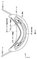
- a biosignal measurement pillow 90 shown in FIG. 44 is applied in place of the biosignal measuring equipment 1, 50, 60, the head brace 300 or the jaw brace 500 in the first to third embodiments described above.
- This biomedical signal measurement pillow 90 has a structure having a portion 91 (hereinafter, also referred to as a convex portion) in which one end is protruded in a convex shape compared to the other end so as to fit to the neck.
- a sheet-like reference electrode 92 is provided on the surface of the slope of the convex portion 91 opposite to the slope facing the other end.
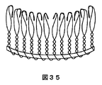
- the surface of the biosignal measurement pillow 90 a plurality of plate-like portions are formed in the region between the root of the slope facing the other end of the convex portion 91 and the predetermined position between the root and the other end. Probe electrodes 93 are arranged at equal intervals. Further, inside the biomedical signal measurement pillow 90, a measurement unit 94 for measuring the potential difference between the probe electrode 93 and the reference electrode 92 is provided. The measurement unit 94 can apply the measurement unit described in the first embodiment or the third embodiment. According to the biomedical signal measurement pillow 90, the burden on the subject can be reduced because the subject is not forced to wear a tool.
- the structure of the biomedical signal measurement pillow 90 is not limited to that shown in FIG. 44.
- various structures such as a structure in which the center is concavely recessed or a structure in which the center is convexly protruded It can apply.
- the arrangement of the probe electrodes 92 is not limited to that shown in FIG.
- a plurality of linear electrodes may be arranged at equal intervals in the row or column direction (FIG. 45A), and may be arranged at equal intervals in the row and column directions. (FIG. 45A).
- the shape of the probe electrode 92 is not limited to that shown in FIG.
- it may be a comb shape (FIG. 46 (A)), a mountain shape (FIG. 46 (B)), or a mezzanine shape (FIG. 46 (C)).
- the thick lines in FIG. 45 indicate fixed portions.
- these electrode shapes can be applied as the shapes of the above-described probe electrodes 13 and 55 and the teeth that constitute the reference electrode 12. Further, in place of the biomedical signal measurement pillow 90, a biomedical signal measurement pillow 100 shown in FIG. 47 can be applied.
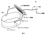
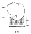
- This biomedical signal measurement pillow 100 has a sheet-like housing 101 and a portion for supporting the head (hereinafter, also referred to as a head support portion) 102.
- the housing 101 is nonconductive, and one surface of the housing 101 is a pedestal on which the head support portion 102 is installed.
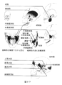
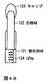
- Support 120 i As shown in FIG. 48, it has a conductive tubular member 121, and a conductive core member 122 slidably inserted into the hollow of the tubular member 121.
- a rounded flexible conductive cap 123 is attached to one end of the core member 122, and a conductive spring 124 is attached to the other end.
- a conductive rubber can be applied to the cap 123.
- the degree of adhesion of the cap 123 with respect to the scalp is improved as compared with the biosignal measurement pillow 90, so the measurement sensitivity is improved.
- the rounded flexible cap 123 is attached to one end of the core member 122, when the head is placed on the head support portion 102, the pain and the like of the contact portion with the head is alleviated. Be done.
- These supports 120 i Can be applied as teeth that constitute the above-described probe electrodes 13, 55, 320A, 320B, 400A, 400B, 510A, 510B, reference electrodes 57C, 77, 370A, 370B, or the reference electrode 12. It is also possible to substitute the form shown in FIG.
- each support 120 i Is also applicable to the conductive fibers 321 described above. Meanwhile, each support 120 i Is also used as a probe electrode.
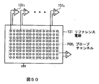
- Probe channel PCH j The supports that make up the corresponding amplifier 130 j Connected to one input end of the j
- the reference electrode 131 is connected to the other input end of the. Amplifier 130 j
- the reference electrode 131 is housed inside the housing 101.
- Probe channel PCH j The supports that make up the corresponding amplifier 130 j Connected to one input end of the j
- the reference electrode 131 is connected to the other input end of the. Amplifier 130 j
- the reference electrode 131
- the biosignal measurement pillow 100 is grounded via a human body or a futon placed on the human body, and is physically not grounded.
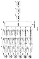
- the configuration of the measurement unit housed inside the housing 101 is shown in FIG. 52 in which the parts corresponding to those in FIG.
- This measurement unit is a probe channel PCH j 4 is different from the measurement unit shown in FIG. 4 in that a function of selecting a probe channel to be sensed is newly added.
- the analysis unit 134 in which new processing is added to the processing in the analysis unit 34 is adopted, and the selector unit 140 is newly provided.
- Parameters (estimation elements) required for this estimation are, for example, each probe channel PCH j Among the biological signals corresponding to the above, the level of the biological signal in a unit time zone, and the probe channel PCH j Is assigned as position information to be assigned.
- the analysis unit 134 selects the probe channel PCH to be selected based on the estimation result of the state (posture) of the object (head) with respect to the head support unit 102. j Is detected, and a selection instruction corresponding to the detection result is applied to the selector unit 140.
- the analysis unit 134 selects the probe channel PCH selected in the second step as the third step. j A change in the state (posture) of the object (head) with respect to the head support 102 is detected based on the biological signal corresponding to.
- the parameters (detection elements) required for this detection are, for example, the rate of decrease of the level per unit time in the biosignal and the number of biosignals larger than the threshold set for the rate of decrease.
- the probe channel PCH selected in the second step j It is assumed that the posture of the head placed on the head support unit 102 has changed when the number of biosignals having a reduction rate larger than the threshold among the biosignals corresponding to f exceeds a predetermined number.
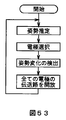
- the analysis unit 134 determines all probe channels PCH as a fourth step.
- each process from the first stage to the third stage is executed again.
- the analysis unit 134 is configured to execute the selection process of the electrode (probe channel).
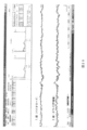
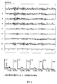
- the experimental result supposing this pillow 100 for biological signal measurement is shown in FIG.54 and FIG.55, and the electrode arrangement
- the biological signal was observed with substantially no problem in the measurement sensitivity.
- the present invention has applicability in the medical industry, the game industry, and the like.
Landscapes
- Life Sciences & Earth Sciences (AREA)
- Health & Medical Sciences (AREA)
- Medical Informatics (AREA)
- Biophysics (AREA)
- Pathology (AREA)
- Engineering & Computer Science (AREA)
- Biomedical Technology (AREA)
- Heart & Thoracic Surgery (AREA)
- Physics & Mathematics (AREA)
- Molecular Biology (AREA)
- Surgery (AREA)
- Animal Behavior & Ethology (AREA)
- General Health & Medical Sciences (AREA)
- Public Health (AREA)
- Veterinary Medicine (AREA)
- Measurement And Recording Of Electrical Phenomena And Electrical Characteristics Of The Living Body (AREA)
Abstract
Description
ところで、睡眠を評価する手法として睡眠ポリグラフ検査が知られている。また、脳波をとらずに、心拍から睡眠サイクルや、睡眠の質の評価に要するパラメータを測定する装置が提案されている(例えば特許文献1)。
一方、例示した特許文献では、睡眠ポリグラフ検査に比べると、被験者に対する負担は低減するが、睡眠の質の評価に要するパラメータはあくまで間接的な推定値となる。したがって、睡眠の質の評価に重要なnon−REM睡眠の深度やREM睡眠の長さや密度は捉えることが困難であり、測定精度が劣るという問題がある。
本発明は以上の点を考慮してなされたもので、被験者に対して過大な負担を強いらせることなく測定精度を向上し得る生体信号測定用装具を提案しようとするものである。
課題を解決するために本発明は、頭部における生体信号の測定に用いられる生体信号測定用装具であって、頭部を支持可能な支持体と、支持体に設けられる電極とを有する。
第1の発明に係る電極は、1対の導電性の線材が環状に形成される環状部分と、該1対の線材が逆方向に巻回され棒状として形成され棒状部分とでなる複数の歯を有し、複数の歯における棒状部分の一端は、支持体に対して直に又は間接的に固定される。
第2の発明に係る電極は、複数の線材でなり、複数の線材の一端は、支持体において頭皮に対向される面に対して行方向及び列方向へ等間隔で固定され、一端から、該一端と他端との間における屈曲位置までの根元部分は面に直交し直立する状態とされ、屈曲位置から他端までの部分は、根元部分に対して斜めに屈曲される。
第3の発明に係る電極は、複数の導電性繊維でなり、当該導電性繊維は、その一端が支持体において頭皮に対向される面に所定間隔で固定され、該面に直交する状態とされる。
本発明では、電極が導電性の線材又は導電性繊維で形成されるので、頭髪の根元に対して滑らかに挿入され頭皮に対する密着性がよくなる。
また、この電極は、その一端を固定端として1点固定されるため、該固定端を中心として、周囲当方へ均等に移動可能である。このため、寝返り等によりいずれの方向から力が加わった場合、その力に対して、頭皮に対する一定の密着度を維持しつつも柔軟に対応することができ、この結果、頭皮に対する一過性の電極離れを低減することができる。
したがって本発明は、頭皮に対する電極の一定の密着度を維持できるため、ペーストにより電極を頭皮に接着しなくとも、睡眠状態を正確に判定するうえで重要な生体信号を一定の感度のもとで取得可能となる。
かくして、被験者に対して過大な負担を強いらせることなく測定精度を向上し得る生体信号測定用装具を実現できる。
図2は、リファレンス電極の構成を概略的に示す図である。
図3は、生体信号測定用装具の装着状態を概略的に示す図である。
図4は、測定部の回路構成を概略的に示す図である。
図5は、第2の実施における生体信号測定用装具の構成を概略的に示す図である。
図6は、プローブ電極の構成を概略的に示す図である。
図7は、リファレンス電極の構成を概略的に示す図である。
図8は、生体信号測定用装具の装着状態を概略的に示す図である。
図9は、頭部装具(斜視)を概略的に示す図である。
図10は、頭部装具(左側面)を概略的に示す図である。
図11は、頭部装具(右側面)を概略的に示す図である。
図12は、頭部装具(上面)を概略的に示す図である。
図13は、頭部装具(下面)を概略的に示す図である。
図14は、頭部装具(前方)を概略的に示す図である。
図15は、頭部装具(後方)を概略的に示す図である。
図16は、アーム脱離状態の頭部装具を概略的に示す図である。
図17は、プローブ電極の構成を概略的に示す図である。
図18は、ヘアバンドの後端部の詳細を示す図である。
図19は、顎部装具(斜視)を概略的に示す図である。
図20は、顎部装具(正面)を概略的に示す図である。
図21は、顎部装具(側面)を概略的に示す図である。
図22は、顎部装具(上面)を概略的に示す図である。
図23は、顔面から頭部に及ぶ神経系を示す図である。
図24は、顔面から頭部に及ぶ血管系を示す図である。
図25は、顔面から頭部に及ぶリンパ系を示す図である。
図26は、顔面から頭部に及ぶ筋肉と表情との関係を示す図である。
図27は、咀嚼筋、眼・耳の筋肉を示す図である。
図28は、実験結果を示すグラフである。
図29は、実験結果を示すグラフである。
図30は、実験結果を示すグラフである。
図31は、生体信号測定用装具の装着状態を概略的に示す図である。
図32は、測定部の回路構成を概略的に示す図である。
図33は、実験結果を示すグラフである。
図34は、他の実施の形態における生体信号測定用装具の装着状態を概略的に示す図である。
図35は、他の実施の形態における電極の構成を概略的に示す図である。
図36は、他の実施の形態における電極構造を概略的に示す図である。
図37は、他の実施の形態における生体信号測定用装具の構成を概略的に示す図である。
図38は、他の実施の形態における電極の構成を概略的に示す図である。
図39は、他の実施の形態におけるヘアバンドと、その装着状態を概略的に示す図である。
図40は、他の実施の形態におけるヘアバンドと、その装着状態を概略的に示す図である。
図41は、他の実施の形態におけるヘアバンドと、その装着状態を概略的に示す図である。
図42は、他の実施の形態におけるヘアバンドと、その装着状態を概略的に示す図である。
図43は、他の実施の形態における額当接部の構造を概略的に示す図である。
図44は、生体信号測定用枕の構成を概略的に示す図である。
図45は、他の実施の形態における電極の配置を概略的に示す図である。
図46は、他の実施の形態における電極の形状を概略的に示す図である。
図47は、生体信号測定用枕の構成を概略的に示す図である。
図48は、支持体の構成を概略的に示す図である。
図49は、就寝状態を概略的に示す図である。
図50は、プローブチャンネルの割り当ての説明に供する概略的な図である。
図51は、生体信号測定用枕の接地状態を概略的に示す図である。
図52は、他の実施の形態における測定部の構成を概略的に示す図である。
図53は、電極選択処理手順を示すフローチャートである。
図54は、実験結果を示すグラフである。
図55は、実験結果を示すグラフである。
図56は、実験時の電極配置を概略的に示す図である。
<1.第1の実施の形態>
[1−1.生体信号測定用装具の構成]
[1−2.装着手順]
[1−3.測定部の構成]
<2.第2の実施の形態>
[2−1.生体信号測定用装具の構成]
[2−2.装着手順]
<3.第3の実施の形態>
[3−1.生体信号測定用装具の構成]
[3−2.装着手順]
[3−3.測定部の構成]
<4.他の実施の形態>
<1.第1の実施の形態>
[1−1.生体信号測定用装具の構成]
図1において、生体信号測定用装具1の構成を示す。この生体信号測定用装具1は、頭部に支持可能な支持体(以下、これをヘアバンドとも呼ぶ)2を有する。このヘアバンド2は、弾力をもつ板状のプラスチック材又は金属材でなりC字状に形成される。
ヘアバンド2の一端には、ゴム等の材質でなる滑り止め部11が設けられる。この滑り止め部11はその先端が湾曲状とされ、頭部に対する食い込みを防止し得るようになされている。
一方、ヘアバンド2の他端にはリファレンス電極12が設けられる。このリファレンス電極12は、図2に示すように、導体でなる複数の歯が一列に並ぶ部(以下、これを歯部とも呼ぶ)12Aと、該歯部12Aを支持する棒状の部(以下、これを歯支持棒とも呼ぶ)12Bとでなる。
歯部12Aの歯は導電性の線材でなり、その中央と根元との間における所定位置から歯先側は環状に形成され、該所定位置から根元側は互いに接する状態で逆方向に巻回され棒状として、隣接する歯と等間隔を保って歯支持棒12Bに固定される。
歯支持棒12Bは歯部12Aの線材よりも太い非柔軟性の導体でなり、ヘアバンド2の他端において、該ヘアバンド2の中央から先端に向う方向と同方向に歯部12Aの各歯先が向くよう取り付けられる。またこの歯支持棒12Bは、頭側の形状に合う程度に、ヘアバンド2の滑り止め部11側に湾曲される。
他方、ヘアバンド2の中央にはプローブ電極13が設けられる。このプローブ電極13は、リファレンス電極12と同じ構造の歯部13Aと、歯支持棒13Bとでなる。この歯支持棒13Bは、ヘアバンド2の中央部分において、ヘアバンド2における湾曲頂部分の面上であって中央から先端に向う方向と直交する方向に歯部13Aの各歯先が向くよう取り付けられる。
[1−2.装着手順]
次に、生体信号測定用装具1の装着手順を説明する。第1ステップでは、ヘアバンド2の裏面が、頭頂と額との間に接するまで被せられる。ヘアバンド2は弾力をもつC字状に形成されているため(図1参照)、両端が近づく方向に所定圧が加わる状態で頭部を挟み込むことができる。したがって、頭部に対するヘアバンド2自体の位置ずれが低減される。
一方、ヘアバンド2の他端に設けられるリファレンス電極12は、ヘアバンド2の中央から先端に向う方向と同方向に歯部12Aの各歯先が向くよう取り付けられ、該歯部12Aは複数の歯を一列に配した構造となっている(図1参照)。このためヘアバンド2は、頭部に被せられる際に、頭髪の根元に対して歯を滑らかに挿入させることができる。
他方、歯部12Aにおける歯の中央と根元との間の所定位置から歯先側は線材で環状に形成されている(図2参照)。このためヘアバンド2における各歯が頭髪根元に絡まり、点接触の場合に比べて、頭皮に対する歯の密着度を向上させ、かつ位置ずれを低減させることができる。これに加えて、被験者に対する痛みを和らげて装着感を向上することができる。
第2ステップでは、頭頂と額との間に接している状態のヘアバンド2が、頭頂位置にスライドされる。ヘアバンド2の中央に設けられるプローブ電極13は、該ヘアバンド2における湾曲頂部分の面上であって中央から先端に向う方向と直交する方向に歯部13Aの各歯先が向くよう取り付けられている(図1参照)。このためヘアバンド2は、頭頂位置にスライドされる際に、頭髪の根元に対して歯を滑らかに挿入させることができる。
また、歯部13Aにおける歯の中央と根元との間の所定位置から歯先側は線材で環状に形成されている(図2参照)。このためヘアバンド2における各歯が頭髪根元に絡まり、点接触の場合に比べて、頭皮に対する密着度を向上させ、かつ位置ずれを低減させることができる。
以上の装着手順を経ることで、例えば図3に示すように、生体信号測定用装具1が頭部に装着され、リファレンス電極12及びプローブ電極13が頭皮に固定される。
リファレンス電極12は線状でなる複数の歯を一列に配したものであるため極めて薄厚となる。したがって枕との間に位置したとしても、リファレンス電極12が存在することによる違和感を低減させることができる。一方、プローブ電極13が位置する頭頂は通常の睡眠時では寝返りしても枕と接することがほぼ回避される部位であるため、プローブ電極13が存在することによる違和感を低減させることができる。
また、リファレンス電極12、プローブ電極13における歯部12A、13Aのうち、中央と根元との間の所定位置から根元側は互いに接する状態で逆方向に巻回され棒状として歯支持棒12Bに固定されている(図2参照)。すなわち、歯支持棒12Bに対して線状の各歯が1点固定された状態であるので、当該固定点を中心として各歯はそれぞれ周囲当方へ均等に移動可能である。このため、寝返り等によりいずれの方向から力が加わったとしても柔軟に対応することができ、当該力が消失すれば速やかに元の状態に復帰することもできる。
したがってこの生体信号測定用装具1は、被験者に対して、睡眠阻害を大幅に低減することができる。また、被験者に対する装着物が多数にわたる睡眠ポリグラフ検査に比べて、被験者に対して装着感を損なわせることなく、該被験者に対する負担を軽減することができる。
ちなみに、この生体信号測定用装具1における電極12、13は、ヘアバンド2によって支持されている。したがってこの生体信号測定用装具1は、着脱時に電極を落とすといったことを防止することができるとともに、電極12、13に接続される配線をヘアバンド2内部に納めることができる。この結果、この生体信号測定用装具1は、着脱時における電極の紛失、あるいは、コードに絡まるといったことを回避することができ、使い勝手を向上することができる。
なお、上述の装着の順序はあくまで一例であり、当該装着の順序に限定されるものではない。
[1−3.測定部の構成]
図4において、リファレンス電極12、プローブ電極13によってセンシングされる生体信号を測定する測定部の構成を示す。測定部における回路基板等は、例えばヘアバンド2の表面又は内部に設けられる。
この測定部30は、増幅部31、フィルタ部32、A(Analog)/D(Digital)変換部33、解析部34、メモリ35及び通信部36を含む構成とされる。
測定部30は、これら各部31~36に対して、例えばヘアバンド2の表面に設けられる操作部から測定開始命令を受けた場合には電池等の電源電圧を供給し、該操作部から測定停止命令を受けた場合には電源電圧の供給を遮断するようになされている。
増幅部31は差動アンプ31Aを有する。差動アンプ31Aは、リファレンス電極12と、プローブ電極13との電位差を信号(以下、これを生体波形信号とも呼ぶ)として増幅し、当該増幅した生体信号をフィルタ部32に出力する。プローブ電極13は頭頂位置に配される電極であるため、差動アンプ31Aから出力される生体波形信号は、主に脳波が反映した信号となる。
リファレンス電極12及びプローブ電極13は、上述したように、頭皮に対する歯部12A、13Aの密着度が向上されつつも位置ずれが低減される構造となっているため、ペーストにより電極を頭皮に接着しなくとも、増幅部31は生体内の電位差を正確に増幅することができ、この結果、測定部での感度が向上される。
さらに、リファレンス電極12が位置される頭側位置と、プローブ電極13が位置される頭頂位置はともに頭蓋骨上となる位置である。したがってリファレンス電極12と、プローブ電極13とから得られる生体波形信号には筋電位成分が低減され、脳波に対する感度が向上される。
フィルタ部32には、脳波に対応する周波数帯域が設定される。フィルタ部32は、生体波形信号から、設定される周波数帯域以外の信号成分を除去し、当該除去した生体波形信号をA/D変換部33に与える。
ちなみに脳波にはデルタ波(1~3[Hz])、シータ波(4~7[Hz])、アルファ波(8~13[Hz])、ベータ波(14~30[Hz])、ガンマ波(31~64[Hz])、オメガ波(65~128[Hz])、ロー波(129~512[Hz])、シグマ波(513~1024[Hz])があるが、これら一部又は全部が脳波に対応する周波数帯域として、所定の操作部で変更可能に設定される。
A/D変換部33は、生体波形信号をディジタルデータ(以下、これを生体波形データとも呼ぶ)に変換し、該生体波形データを解析部34に与える。
解析部34は、CPU、ROM、CPUのワークメモリであるRAM、スピーカ及び時計(計時部)を含む構成とされる。このROMには、解析処理を実行させるプログラムや、人体表面に対して電極が非接触であるとすべきレベル(以下、これを非接触レベル閾値とも呼ぶ)を示すデータなどが記憶される。
解析部34は、測定開始命令を受けた場合、ROMに格納されるプログラムをRAMに展開し、該プログラムにしたがって、電極の接触の有無を解析する処理(以下、これを電極接触検出処理とも呼ぶ)と、波形解析処理とを実行する。
この電極接触解析処理の具体的な処理内容の一例を説明する。解析部34は、規定期間ごとの生体波形データにおけるレベルの平均と、該平均に対して設定される非接触レベル閾値とを比較する。
このレベル平均が非接触レベル閾値を下回る場合、解析部34は、人体表面に対して電極が非接触状態であるとして処理を中止し、電極を再装着すべきことを、スピーカを介して通知する。
これに対してレベル平均が非接触レベル閾値を上回る場合、解析部34は、人体表面に対して電極が接触状態であるとして、当該規定期間における生体波形データをメモリ35に記憶する。
このようにして電極接触解析処理が実行される。ただし、この処理内容はあくまで一例である。
次に、波形解析処理の具体的な処理内容の一例を説明する。すなわち解析部34は、第1段階として、生体波形データから脳波波形、眼電位波形及び筋電位波形の各成分を認識する。
上述したように、リファレンス電極12が位置される頭側位置と、プローブ電極13が位置される頭頂位置はともに頭蓋骨上となる位置であるため、生体波形信号には筋電位成分が低減される。また一般に、ペーストを用いて頭皮に対して電極が非接着となる場合には生体波形信号の波形レベルが小さくなる。しかしながら、生体波形データのスペクトルであれば、脳波波形、眼電位波形及び筋電位波形の各成分を得ることができることが確認されている。
解析部34は、第2段階として、脳波波形及び眼電位波形を用いて入眠時刻を判定する。具体的には、α波が消失し、SEM(Slow Eye Movement)が出現する条件を満たす時点が入眠時刻とされる。
解析部34は、第3段階として、脳波波形、眼電位波形及び筋電位波形を用いて睡眠に関する各種判定を行う。この実施の形態では、non−REM睡眠の深度及び質の判定と、REM睡眠の開始時刻、終了時刻及び質の判定とが行われる。
non−REM睡眠の深度及び質の判定は、単位時間当たりのδ波の出現数(出現密度)と、該δ波の振幅値とを用いて行われる。
一方、REM睡眠の開始時刻の判定は、δ波が消失し、REMが出現し、筋電位が消失する条件を満たす時点とされ、REM睡眠の終了時刻の判定は、REMが消失し、筋電位が出現する条件を満たす時点とされる。
他方、REM睡眠の質の判定は、REM睡眠の開始時刻から終了時刻までの単位時間当たりのREMの出現数(出現密度)を用いて行われる。
解析部34は、第4段階として、脳波波形及び筋電位波形を用いて覚醒時刻を判定する。具体的には、β波が出現し、筋電位が出現する条件を満たす時点が覚醒時刻とされる。
解析部34は、第5段階として、non−REM睡眠と、REM睡眠との出現数、割合及び出現サイクル等を用いてサイクルパターンを判定する。
解析部34は、第6段階として、各ステップでの判定結果と、その判定に用いたパラメータ(判定要素)とをデータ(以下、これを判定結果データとも呼ぶ)として生成し、これを生体波形データに関連付けてメモリ35に記憶する。
このようにして波形解析処理が実行される。ただし、この処理内容はあくまで一例である。
メモリ35は、解析部34又は通信部36から与えられる命令にしたがって書き込み処理又は読み出し処理を実行するようになされている。なお、メモリ35は測定部3に内蔵されるものに限らず、USBメモリ、SDカードメモリ又はCFカードメモリのようにリムーバブルメモリを適用可能である。
通信部36は、操作部から送信命令が与えられた場合、メモリ35に記憶された各種データを、所定の外部機器に例えば無線通信に送信するようになされている。
<2.第2の実施の形態>
[2−1.生体信号測定用装具の構成]
図5において、生体信号測定用装具50の構成を示す。この生体信号測定用装具50は、頭部に支持可能な支持体(以下、これをヘアバンドとも呼ぶ)51を有する。このヘアバンド51は、布材又はゴム材でなり帯状乃至環状に形成される。
ヘアバンド51の対向位置には、ゴム等の柔軟性を有する材質でなる板状又は線状のアーム52(52A、52B)が、該アーム52に対して取外自在の連結部材により取り付けられる。このアーム52の先端には板状の電極支持体54が連結される。
連結部材にはこの実施の形態では例えばスナップボタン53(53A、53B)が適用される。アーム52長は、ヘアバンド51が装着されるべき位置でのスナップボタン53の位置と、電極支持体54が装着されるべき位置との直線距離よりも短くされる。
電極支持体54の一方の面にはプローブ電極55が設けられる。また電極支持体54における表面の所定位置ではリード線56が電極支持体54の内部から引き出され、該リード線56の先端にはリファレンス電極57が設けられる。
プローブ電極55は、図6に示すように、導電性の線材でなる複数の歯を、行方向及び列方向へ等間隔に配した構造でなる。これら歯はその根元と先端との間の所定位置において屈曲され、該先端は丸みを帯びた形状とされる。屈曲角は、歯先から屈曲位置までの歯部分が、歯元から屈曲位置までの歯部分に対して斜めとなるよう、90[°]に数[°]を合算した程度とされる。
リファレンス電極57は、図7に示すように、耳朶と同程度の表面積を有するコイン形状の挟み片57Aと、該挟み片57Aとの連結される挟み片57Bと、該挟み片57Bのうち挟み片57Aと対向される面に設けられるリベット57Cとでなる。
挟み片57A及び挟み片57Bの連結部57Dは、当該連結部57Dを支点として挟み片57Aと挟み片57Bとが離間する方向又は接近する方向に移動可能に連結される。リベット57Cと挟み片57Bとの間には、リード線56の先端が電気的及び機械的に固定される。
[2−2.装着手順]
次に、生体信号測定用装具50の装着手順を説明する。第1ステップでは、ヘアバンド51が、頭部周囲に装着される。
第2ステップでは、ヘアバンド51に対してアーム52を介して連結される電極支持体54が頭頂に装着される。具体的には、電極支持体54が、プローブ電極55を有する面が頭部に対向された状態で頭頂位置に置かれ、その後、プローブ電極55における歯先方向と同等の方向へスライドされる。
アーム52はゴム等の柔軟性を有する材質とされ、当該アーム長はヘアバンド51が装着されるべき位置でのスナップボタン53の位置と、電極支持体54が装着されるべき位置との直線距離よりも短くされている。したがって電極支持体54が頭頂に装着される場合、該電極支持体54には、アーム52が元のアーム長に戻ろうとする力が、頭頂に押さえ付ける力として働き、該電極支持体54に設けられるプローブ電極55が、頭皮に密着される。
またプローブ電極55を構成する線状の複数の歯は、その根元と先端との間の所定位置において屈曲され、該先端は丸みを帯びた形状とされる(図6参照)。したがって、電極支持体54をスライドさせる際には、各歯が頭皮を傷つけることなく、頭髪の根元に対して歯を滑らかに挿入させることができる。これに加えて、電極支持体54のスライドによりプローブ電極55の各歯は頭髪根元に絡まる。このためこのプローブ電極55は、非屈曲の歯を採用する場合に比べて、頭皮に対する密着度を向上させ、かつ位置ずれを低減させることができる。
一方、プローブ電極55が位置する頭頂は通常の睡眠時では寝返りしても枕と接することがほぼ回避される部位であるため、プローブ電極55が存在することによる違和感を低減させ、また寝返りによるプローブ電極55の位置ずれを回避することができる。
したがってこの生体信号測定用装具50は、被験者に対して、睡眠阻害を大幅に低減することができる。また、被験者に対する装着物が多数にわたる睡眠ポリグラフ検査に比べて、被験者に対して装着感を損なわせることなく、該被験者に対する負担を軽減することができる。
第3ステップでは、リファレンス電極57が耳朶に装着される。具体的には、コイン形状の挟み片57Aと、挟み片57Bに設けられるリベット57C(図7参照)とによって耳朶が挟み込まれる。挟み片57Aとリベット57Cと丸みを帯びた部分で耳朶が挟み込まれるため、被験者に対する痛みを緩和でき、この結果、被験者に対する睡眠阻害を大幅に低減することができる。
以上の装着手順を経ることで、例えば図8に示すように、生体信号測定用装具50が頭部に装着され、プローブ電極55が頭皮に、リファレンス電極57が耳朶にそれぞれ固定される。ただし、上述の装着の順序はあくまで一例であり、当該装着の順序に限定されるものではない。
ところで生体信号測定用装具50における測定部は、例えば電極支持体54の表面又は内部に設けられる。この測定部の構成は、生体信号測定用装具1における測定部と同じ構成であるためここでは省略する。
なお、プローブ電極55は、上述したように、頭皮に対する歯の密着度が向上されつつも位置ずれが低減される構造となっているため、ペーストにより電極を頭皮に接着しなくとも、測定部は生体内の電位差を正確に増幅することができ、この結果、測定部での感度が向上される。
また、プローブ電極55が位置される頭頂位置はともに頭蓋骨上となる位置である。一方、リファレンス電極57が位置される筋肉のない耳朶である。したがってプローブ電極55と、リファレンス電極57とから得られる電位差には筋電位成分が低減され、脳波に対する感度が向上される。
さらに、リファレンス電極57が位置される耳朶は、頭部から比較的はなれた位置であるため、プローブ電極55が位置される頭頂位置との間の脳の挙動を、プローブ電極55と、リファレンス電極57との電位差として直接的に捉えることができる。
なお、プローブ電極55、リファレンス電極57は、ヘアバンド51に対してアーム52及び電極支持体54を介して支持されている。したがってこの生体信号測定用装具50は、着脱時に電極を落とすといったことを防止することができるとともに、各電極55、56に接続される配線をヘアバンド51又は電極支持体54の内部に納めることができる。この結果、この生体信号測定用装具50は、着脱時における電極の紛失、あるいは、コードに絡まるといったことを回避することができ、使い勝手を向上することができる。
また、アーム52及び電極支持体54は、スナップボタン53を介して取り外し可能である。したがってこの生体信号測定用装具50は、ヘアバンド51を洗浄させることができるとともに、単に髪留め具や防寒具として利用させることもできる。
<3.第3の実施の形態>
[3−1.生体信号測定用装具の構成]
第3の実施の形態における生体信号測定用装具は、頭部装具300(図9~図16)と、顎部装具500(図19~図22)とによって構成される。
頭部装具300は、頭部に支持可能な支持体(ヘアバンド)310を有する。このヘアバンド310は、プラスチックや金属等のように屈曲性かつ剛性を有する板材でなりC字状に形成される。したがって、頭部の形状の相違に問わず柔軟にフィットし、かつその状態が保持可能となる。
このヘアバンド310では一方の端部が額側であり、他方の端部が後頭側であると視認可能となるよう、該一方の端部(以下、これを前端部とも呼ぶ)が他方の端部(以下、これを後端部)よりも高い位置として形成される(図10、図11参照)。
すなわち、ヘアバンド310の断面が、該ヘアバンド310における長さ方向及び幅方向の中心を通る垂線を境界として前後非対称であり、該中心から前端部までのヘアバンド310の長さが、該中心から後端部までのヘアバンド310の長さよりも短い状態となる。
またヘアバンド310の幅は、国際10−20法における「F3」と「P3」を結ぶ直線と、「F4」と「P4」を結ぶ直線との間の距離よりも小さい値とされる。具体的には、25[mm]以下が好ましい。したがって、ヘアバンド310は、頭の側方部分を開放しつつも、正中矢状面を通る輪郭部分に対して柔軟にフィット可能となる。
ヘアバンド310における内面には、該ヘアバンド310の中央位置に所定間隔を隔てて凹部(窪み)311、312が設けられる(図9参照)。この間隔は、例えば、成人における正中中心部(国際10−20法におけるCz)と、正中頭頂部(国際10−20法におけるPz)との距離の平均とされ、前端部が基準とされる。
これら凹部311、312にはプローブ電極320A、320Bが設けられる(図9~図11参照)。プローブ電極320A、320Bは、図17に示すように、複数の導電性繊維321を水平方向及び垂直方向へ所定間隔ごとに直立状態で基板322に植え付けたブラシ構造とされる。
導電性繊維321の材質は、例えばカーボン、アモルファス、ステンレス又はサンダーロン等とされる。導電性繊維321の太さ(繊維径)又は太さは、被験者に対する痛みを生じさせずしなやかな剛性をもつ程度とされる。この実施の形態では導電性繊維321の太さは25[μm]とされ、導電性繊維321の長さは10[mm]とされる。
基板322は、凹部311、312の底面に固定される。なお、導電性繊維321の可動性が損なわない程度に、導電性繊維321の植付面積と、凹部311、312の表面積とがそれぞれ設定される。また、ヘアバンド310の内表面から導電性繊維321の先端が頭部に対するヘアバンド310のフィット性を損なわない程度に突出するよう、導電性繊維321の長さと凹部311、312の深さとがそれぞれ設定される。
ヘアバンド310のうち凹部312と後端部との間には、ヘアバンド310の長手方向へ所定間隔ごとに複数の溝313が形成される(図9参照)。これら溝313が形成された部分には、該部分を芯としてヘアバンド310の長手方向へスライド可能なアジャスタ部330が設けられる(図9~図11、図14~図16参照)。
アジャスタ部330の内面のうちヘアバンド310の溝313と対向される部分には、該溝313と嵌合可能な爪(図示せず)が設けられ、ヘアバンド310の全長が段階的に調整可能となっている。したがって、頭の寸法や形状にあわせてヘアバンド310の装着性が高められる。
これら溝313のうち前端部に対して最も近い溝313A(図18)に爪が嵌合されている場合のヘアバンド310の全長と、最も遠い溝313B(図18)に爪が嵌合されている場合のヘアバンド310の全長との差はこの実施の形態では30[mm]とされる。
またこの実施の形態では、各溝313の中間となる溝313C(図18)が基準とされ、その中間の溝313Cに対するアジャスタ部330の長さは、該中間の溝313Cに爪が嵌合されている場合のアジャスタ部330の開放端が後頭中央部(国際10−20法におけるOz)の直上となる長さとされる。
したがって、頭部の突出部分に対するアジャスタ部330の先端部分の接触を避けるようアジャスタ部330の開放端が配置可能であるため、被験者に対する睡眠時の痛みが緩和され、この結果、被験者に対する睡眠阻害が大幅に低減される。
なお、凹部312から所定間隔だけ後端部側に隔てた位置から後端部までの部分の幅は、該位置から前端部までの幅よりも狭く形成され(図18参照)、当該位置における段差部分がアジャスタ部330に対するストッパーとされる。したがって、別途ストッパーを設ける場合に比べて部品点数が抑えられ、その分だけ小型化が可能となる。
ヘアバンド310の後端(アジャスタ部330の開放端)には後頭に当接される部(以下、これを後頭当接部とも呼ぶ)340が取り付けられる(図9~図11、図13~図16参照)。後頭当接部340は、その幅が連結部分では狭く次第に広がりその途中から先端に近づくにつれて狭くなる尖形ヒレ状ないしスペード状でなり、額に当接すべきとしてヘアバンド310の前端に取り付けられる部(後述する額当接部350)よりも広い面積とされる。したがって、頭部に対する安定性が高められる。
後頭当接部340のうち中心とその近傍の芯領域340Aは硬い素材とされ、当該芯領域340Aの以外の周辺領域340Bはシリコン又はウレタン等の柔らかい素材とされる(図18参照)。したがって、頭部に対する密着性が高められ、また頭部に対する食い込みが抑制される。
芯領域340Aの内面側には穿設孔341A、341Bを介して髪留め(図示せず)又は吸盤(図示せず)が着脱自在に取り付けられる。したがって、髪の有無に問わず、頭部に対する安定性がより一段と高められる。
なおこの芯領域340Aは周辺領域340Bに比べて、髪留め又は吸盤の高さ程度に窪んだ状態とされる。したがって、髪留め又は吸盤を取り付けたことに起因して後頭当接部340が頭部から浮くという状態が未然に回避される。
芯領域340Aと、アジャスタ部330との接続部分は、ヘアバンド310の内面に対する後頭当接部340の内面の角度を可変する角度調整機構342が設けられる。したがって、頭部の接触部分に対する後頭当接部340の内面の角度の調整が可能となり、この結果、頭部に対する安定性がより一段と高められる。
ヘアバンド310の前端部には額に当接される部(以下、これを額当接部とも呼ぶ)350が取り付けられる(図9~図16参照)。額当接部350は涙滴状でなり、シリコン又はウレタン等の柔らかい素材とされる。したがって、額に対する密着性が高められ、また額に対する食い込みが抑制される。
額当接部350における内面には、その内面を上側領域と下側領域に分割する凹状溝351が形成される(図9~図11、図15、図16参照)。この凹状溝351によって額当接部350の柔軟性が向上され、この結果、額に対する額当接部350の密着性がより高められる。
ヘアバンド310の外面には、電子機器を収める突起状の筐体(以下、これを突起筐体とも呼ぶ)360が設けられる(図9~図16参照)。この突起筐体360は、固定領域361と突起領域362とからなる(図9~図12、図14、図16参照)。固定領域361は、額当接部350の直上のヘアバンド310外面に固定される。この固定領域361の側面の上段と下段には、それぞれ1対のアーム取付口101、102、103、104が設けられる(図16参照)。
突起領域362は、ヘアバンド310から分離され、ヘアバンド310の頂部外面から所定距離隔てた上方に突き出される。したがって、基板は頭への装着性を考慮離間される。すなわち、ヘアバンド310の装着時における湾曲状態の変化を妨げることなく、滑らかにヘアバンド310を装着させることが可能とされる。
突起領域362の形状は、湾曲の程度がヘアバンド310に比べて緩やかな扁平状とされる。したがって、ヘアバンド310内部に電子機器を収める場合に比べて回路基板の選択幅が広げられ、またヘアバンド310の屈曲による影響が回避される。
突起領域362の上面には、数秒間の押し操作によって電源をオン又はオフさせる長押しボタン363が設けられる(図9、図10、図12、図16参照)。したがって、就寝時や起立時に周囲の物体に当てて誤って電源をオン又はオフすることが抑制される。
突起領域362の側面には、例えばSD(Secure Digital)カードやUSB(Universal Serial Bus)メモリ等のリムーバブルメディアに対する複数種類のコネクタ364(図9~図12、図14、図16参照)が設けられる。
上段のアーム取付口101、102には、1対のリファレンス電極370A、370Bを支持するアーム380A、380Bが着脱自在に取り付けられる(図9~図11参照)。これらアーム380A、380Bは、頭部表面に沿って耳裏を経由して耳朶に届く程度の長さとされ、その先端には耳朶にリファレンス電極370A、370Bを取り付ける部(以下、これを耳朶取付部とも呼ぶ)390A、390Bが設けられる(図9~図11参照)。
下段のアーム取付口101、102には、1対のプローブ電極400A、400Bを支持するアーム380C、380Dが着脱自在に取り付けられる(図9~図11参照)。これらアーム380C、380Dは、前頭骨、頬骨弓、頬骨眼窩突起に囲まれる窪み(以下、これをこめかみとも呼ぶ)に届く程度の長さとされ、その先端にはこめかみにプローブ電極400A、400Bを取り付ける部(以下、これをこめかみ取付部とも呼ぶ)410A、410Bが設けられる(図9~図11参照)。
各アーム380は、シリコン、PBT又はPP等の柔らかい素材とされ円筒状に形成される。各アーム380の内部にはピアノ線やワイヤー等の剛性のある線状の部材(図示せず)が付される。したがって、アーム380の形状が柔軟に調整可能となりかつその調整後の状態を保持可能となる。
耳朶取付部390A、390B(図9~図11)は、アーム380A、380Bの先端に連結される枠体391A、391Bを有し、該枠体391A、391Bの下端にはジャック形式のコネクタ392A、392Bが設けられる。
この枠体391A、391Bでは、該枠体391A、391Bの平面領域の全体又は辺縁を除く中心領域に、磁性を帯びたリファレンス電極370A、370Bが露出する構造される。またこの枠体391A、391Bには、柔軟性をもつ板状の連結部材393A、393Bを介して円盤状の磁石394A、394Bが取り付けられる。
したがってこの耳朶取付部390A、390Bは、連結部材393A、393Bを折り曲げて、磁石394A、394Bと、リファレンス電極370A、370Bとの間に耳朶を挟み込み、該リファレンス電極370A、370Bを磁力によって耳朶に固定できるようになっている。
こめかみ取付部410A、410B(図9)は、アーム380A、380Bの先端に連結される枠体411A、411Bを有し、該枠体411A、411Bの平面領域の全体又は辺縁を除く中心領域に、プローブ電極400A、400Bが露出する構造される。この枠体411A、411Bの辺縁には、固体ジェル等のように皮膚に対して粘着性をもつシートが取り付けられる。したがって、こめかみに対するプローブ電極400A、400Bの安定性と密着性が確保される。
なお、枠体391A、391B、411A、411Bには、「上右」「上左」「下右」「下左」が視認可能となるようそれぞれ異なる形状が割り当てられる。
各リファレンス電極370と、各プローブ電極400にはリード線(図示せず)が接続され、リード線は、対応するアーム380内空に配される線状の部材(図示せず)に沿って、突起筐体360における固定領域361の内部に引き出される。またヘアバンド310に取り付けられる各プローブ電極320にもリード線(図示せず)が接続され、該リード線は、ヘアバンド310内を経由して突起筐体360における固定領域361の内部に引き出される。
固定領域361の内部には、各電極320、370、400に割り当てられるアンプ(図示せず)に接続され、これらアンプの接地線はそれぞれ1つの接地点に接続される。これはスター型アースと呼ばれる接地手法である。
固定領域361が配される位置は、該位置に対して、各電極320、370、400それぞれが最短距離となる関係にある位置とされる。このため、これら電極320、370、400に対するリード線に重畳される外乱ノイズが大幅に低減される。また各電極320、370、400に割り当てられるアンプの接地線が固定領域361内で一点に集中されるため、当該接地点によるループが低減される。
なお、固定領域361では、アンプのほかに、ノイズの影響の程度が高いアナログ系の電子素子が優先して設けられ、これに対して突起領域362では、ノイズの影響の程度が小さいディジタル系の電子素子が優先して設けられる。
顎部装具500は、柔軟生のある素材と剛性のある素材とを組み合わせて形成される筐体501を有し、該筐体501には下顎におけるオトガイ隆起の形状に対応した面(以下、これをオトガイ隆起対向面とも呼ぶ)502が形成される。このオトガイ隆起対向面502には、固体ジェル等の粘着性を有するシートが取り付けられる。
したがって、鏡等を見なくてもオトガイ隆起対向面502の形状によってオトガイ隆起に対して手探りで容易にフィットさせることが可能であり、そのフィットした状態の安定化が図れる。
筐体501の内部には、プローブ電極510A、510B、電子基板520及びレール530が搭載される。
プローブ電極510A、510Bは円盤状でなり、例えばオトガイ結節における垂線上の位置に配される。
電子基板520は柔軟性のある基板とされ、オトガイ隆起対向面502に沿う曲線を呈した状態で一方のプローブ電極510Aと他方のプローブ電極510Bとの間に配される。電子基板520には、プローブ電極510A、510Bによってセンシングされる生体信号を増幅するためのアンプ(図示せず)が配される。
レール530は、POM等の摺動性性の高い素材とされ、オトガイ隆起対向面502に沿う曲線を呈した状態で水平に配される。このレール530には上段ガイド溝531Aと下段ガイド溝531Bとが形成される。
上段ガイド溝531Aの一端には杭状のストッパー532Aが固定され、該ストッパー532Aには上段ガイド溝531Aの軌道に沿って伸縮するスプリング533Aの一端が固定される。このスプリング533Aの他端には、上段ガイド溝531Aに挿通されるアーム534Aの一端が固定される。アーム534Aの他端は、耳朶取付部390Aのコネクタ392に対応するピン形式のコネクタ(図示せず)が設けられ、該コネクタ392に着脱される。
下段ガイド溝531Bの一端には杭状のストッパー532Bが固定される。この一端は、上段ガイド溝531Aでストッパー532Aが設けられる一端とは反対側に位置する端とされる。
上段ガイド溝531Aの場合と同様に、ストッパー532Bにはスプリング(図示せず)の一端が固定され、該スプリング(図示せず)の他端にはアーム(図示せず)の一端が固定される。アームの他端は、耳朶取付部390Bのコネクタ392に対応するピン形式のコネクタ(図示せず)が設けられ、該コネクタ392に着脱される。
したがって、スプリング533A、533Bは、アーム534A、534Bを、顎部装具500と耳朶取付部390Aとの間の距離に応じた長さに調整し、また互いに相反する押力を与えて顎部装具500の位置ずれを防止することが可能となる。
なお、アーム534A、534Bは、シリコン、PBT又はPP等の柔らかい素材とされ円筒状に形成される。アーム534A、534Bの内部にはピアノ線やワイヤー等の剛性のある線状の部材(図示せず)が付される。したがって、アーム534A、534Bを下顎角部分上の顔面に沿って配することが可能となりかつその調整後の状態を保持可能となる。
またストッパー532A、532Bは、上段ガイド溝531A、531Bの軌道方向に所定間隔ごとに形成される複数の嵌込部535(図20参照)に対する嵌込先を変更することで、その固定位置を調整することができるようになっている。
[3−2.装着手順]
次に、生体信号測定用装具の装着手順を説明する。第1ステップでは、頭部の前後方向にヘアバンド310が被せられる。
ヘアバンド310の前端部が後端部よりも高い位置として形成されているため(図10、図11参照)、被験者に対して頭部装具300の前後方向を直感的に把握させることができる。またヘアバンド310はプラスチックや金属等のように屈曲性かつ剛性を有する板材でなり、その幅は、国際10−20法における「F3」と「P3」を結ぶ直線と、「F4」と「P4」を結ぶ直線との間の距離よりも小さい値とされる。
このためヘアバンド310は、頭の側方部分を開放しつつも、正中矢状面を通る輪郭部分に対して柔軟にフィットし、この結果、被験者が横になることによる偏頭痛や不快感が大幅に緩和される。
またヘアバンド310は、正中矢状面を通る輪郭部分を経て、頭部の前後方向を挟み込む構造とされているため、該ヘアバンド310の自重が正中矢状面を通る輪郭部分を圧迫することになる。
しかし、図23~図25に示すように、頭部から頭部に及ぶ神経群、血管群、リンパ群はヘアバンド310の内面が接する部分(正中矢状面を通る輪郭部分)には介在しない。また図26、図27に示すように、顔面から頭部に及ぶ筋肉も、ヘアバンド310の内面が接する部分(正中矢状面を通る輪郭部分)には介在しない。
したがって、例えば第1の実施の形態のように、正中矢状面を通る輪郭部分を経ずに頭部を挟み込む構造の場合に比べて、神経、血管系、リンパ系、筋肉系に対するヘアバンド310の圧迫量が最小限に抑えられる。この結果、装着による偏頭痛や不快感が大幅に緩和される。
なお、図23は、[online]、“顔面神経”フリー百科事典ウィキペディア、[平成22年5月27日検索]、インターネット<URL:http://ja.wikipedia.org/wiki/%E9%A1%94%E9%9D%A2%E7%A5%9E%E7%B5%8C>に記載されているものである。一方、図24、図25は、F.H.マティーニ著、「カラー人体解剖図」、西村書店、2003年発行、8頁に記載されているものである。他方、図26、図27は、河合良訓監修、「肉単」、NTS出版、2007年6月8日 第26刷発行、7−8頁に記載されているものである。
一方、ヘアバンド310の内面では、頭部に対するヘアバンド310のフィット性を損なわない程度に、プローブ電極320A、320B(導電性繊維321)の先端が突出するため、該頭部に対する導電性繊維321の密着度が向上される。
一般に、頭皮は、顔面等のように比較的少ない毛量の皮膚よりも皮脂分泌が多く代謝も早いので、角質層が生じ易い。したがって、従来の脳波測定における電極の装着前には頭皮の洗浄が必要となる。
しかしながらプローブ電極320A、320Bは、基板322に対して複数の導電性繊維321をそれぞれ直立状態で植え付けた構造とされるため、該導電性繊維321の全部又は一部が頭髪を避けるとともに皮脂及び角質層を貫通して頭皮に接触される。したがって、電極の頭皮の洗浄が省略されたとしても脳波の測定することが可能であり、この結果、実質的な測定精度を損なうことなく被験者に対する負担を軽減し、長時間の脳波測定が可能となる。
また、従来の脳波測定における電極の装着時には、頭皮に対する電極の接触を保持するためにペーストの塗布が必要となる。
しかしながらプローブ電極320A、320Bでは、基板322に対して各導電性繊維321がそれぞれ1点固定された状態であるので、当該固定点を中心として各導電性繊維321はそれぞれ周囲当方へ移動可能である。
このため、ペーストの塗布が省略されたとしても頭の形状を問わず頭皮に対する導電性繊維321の接触が維持される。さらに、寝返り等によりいずれの方向から力が加わったとしてもその力に対応しながらも導電性繊維321の接触が維持され、当該力が消失すれば速やかに元の状態に復帰しながらも導電性繊維321の接触が維持される。
ここで、実験結果を図28~図30に示す。図28は、頭頂(正中中心部)に対して、ペーストを付して皿状の電極を配置した場合と、ペーストを付さずに逆U字状の電極を配置した場合における生体信号のセンシング結果を示したものである。
図29は、額に対して、バイオロードを配置した場合と、ペーストを付さずに逆U字状の電極を配置した場合における生体信号のセンシング結果を示したものである。図30は、頭頂(正中中心部)に対して、バイオロードを配置した場合と、ペーストを付さずにブラシ構造の電極(試作したプローブ電極320)を配置した場合と、ペーストを付さずに逆U字状の電極を配置した場合における生体信号のセンシング結果を示したものである。
これら実験結果から分かるように、ブラシ構造の電極(試作したプローブ電極320)は、ペーストの塗布が省略されたとしても、従来のペーストを塗布した皿電極でセンシングする従来と同様の結果が得られる。
第2ステップでは、頭部に対する後頭当接部340の位置の微調整が行われる。すなわち、後頭当接部340が後頭中央部(国際10−20法におけるOz)の直上に位置するよう、アジャスタ部330によってヘアバンド310の長さが調整される。頭部の突出部分に対する接触を避けて後頭当接部340が配置されるため、被験者に対する睡眠時の痛みが緩和され、この結果、被験者に対する睡眠阻害が大幅に低減される。
また頭部の接触面に対して後頭当接部340の内面が略平行となるよう、角度調整機構342(図18)によって後頭当接部340の角度が調整される。したがって、頭部に対する安定性が高められる。
第3ステップでは、後頭当接部340に対して着脱自在に取り付けられる髪留め(図示せず)又は吸盤(図示せず)が髪又は頭皮に対して装着される。したがって、髪の有無に問わず、頭部に対する安定性がより一段と高められる。
第4ステップでは、頭部表面に沿って耳裏を経由して耳朶に先端が位置するようアーム380A、380Bの形状が適宜変更され、顔表面に沿ってこめかみに先端が位置するようアーム380C、380Dの形状が適宜変更される。
各アーム380は柔らかい素材で円筒状に形成され、その内部には剛性のある線状の部材(図示せず)が付されているため、被験者に対してアーム380の形状を柔軟に調整させることができ、またその調整後の状態を保持することができる。
第5ステップでは、アーム380A、380Bの先端に設けられる耳朶取付部390A、390Bが耳朶に取り付けられ、アームC、380Dの先端に設けられるこめかみ取付部410A、410Bがこめかみに取り付けられる。
耳朶取付部390A、390Bは、磁石394A、394Bと、リファレンス電極370A、370Bとの間に耳朶を挟み込む構造とされているため、耳朶に対するリファレンス電極370A、370Bの安定性と密着性を確保できる。また、被験者に対して速やかにリファレンス電極370A、370Bを固定させることが可能となる。
こめかみ取付部410A、410Bは、その枠体411A、411Bの辺縁に対して、皮膚に粘着性をもつシートを取り付けているため、こめかみに対するプローブ電極400A、400Bの安定性と密着性を確保できる。また、被験者に対して速やかにリファレンス電極370A、370Bを固定させることが可能となる。
第6ステップでは、顎に対して筐体501が被せられる。この筐体501には下顎におけるオトガイ隆起の形状に対応した面(オトガイ隆起対向面)502が形成されている。このため、被験者に対して、鏡等を見させずにオトガイ隆起対向面502の形状によって手探りでオトガイ隆起へ速やかにフィットさせることが可能であり、そのフィットした状態の安定化が図れる。
第7ステップでは、アーム534A、534Bが引き伸ばされ、下顎角部分上の顔面に沿うようアーム380A、380Bの形状が適宜変更される。アーム534A、534Bは柔らかい素材で円筒状に形成され、その内部には剛性のある線状の部材(図示せず)が付されているため、被験者に対してアーム534の形状を柔軟に調整させることができ、またその調整後の状態を保持することができる。
第8ステップでは、アーム534A、534Bの先端のピン型コネクタがアーム耳朶取付部390Aのジャック型コネクタに差し込まれる。アーム534は、レール530のガイド溝531のうちアーム534の左右とは逆側寄りに固定されるストッパー532に対してスプリング533を介して連結される。
したがって、アーム534は、スプリング533によって、顎部装具500と耳朶取付部390Aとの間の距離に応じた長さに調整され、また顎部装具500はスプリング533の互いに相反する押力によって位置ずれが防止され、安定化される。
以上の装着手順を経ることで、例えば図31に示すように、頭部装具300、顎部装具500が頭部、顎に装着される。この結果、プローブ電極320A、320Bが頭皮に、プローブ電極400A、400Bがこめかみに、リファレンス電極370A、370Bが耳朶に、プローブ電極510A、510Bがオトガイ隆起にそれぞれ固定される。ただし、上述の装着の順序はあくまで一例であり、当該装着の順序に限定されるものではない。
[3−3.測定部の構成]
図4との対応部分に同一符号を付した図32において測定部600の構成を示す。この測定部600は、増幅部631、A/D変換部33、フィルタ部632、演算部650、解析部634、メモリ35及び通信部36を含む構成とされる。
増幅部631は、各電極320、370、400に割り当てられるアンプ631A~631Fを有し、当該電極320、370、400と、基準電位(接地点)との差を増幅する。
フィルタ部632は、ディジタルフィルタである点で、アナログフィルタであるフィルタ部32とは相違しない。フィルタ部632は、各電極320、370、400に割り当てられるフィルタ部632A~632Fを有し、設定される周波数帯域以外の信号成分を除去した上で、対応するA/D変換部33A~33Fでの変換結果が得られる。
具体的には、脳波の周波数帯域を選択するバンドパスフィルタ、ACノイズを除去するノッチフィルタ又はそれらの組み合わせなどが好ましい。
ところで、睡眠ポリグラフ検査では被験者に取り付けられる器具とは別室に測定装置が配されるため、該器具と測定装置間の距離は必然的に長くなる。したがって、従来の睡眠ポリグラフ検査では、器具と測定装置間の接続線に重畳される外乱ノイズ等の影響を避けるため、シールドルームが必須となる。
しかしながらこの突起筐体360における固定領域361が配される位置は、該位置に対して、各電極320、370、400それぞれが最短距離となる関係にある位置とされ、該電極320、370、400に割り当てられるアンプの接地線が固定領域361内で一点に集中される。このため、シールドルームがなくても、ノイズの影響が大幅に低減され、この結果、一般家庭であっても脳波測定が可能となる。
ところで、一般家庭で脳波測定が可能となると、様々な外乱ノイズが存在するものである。代表的なものとして、コンセントから生じるノイズがある。例えば、コンセントから生じるノイズの周波数帯は、例えば東京と関西等のように地域ごとに異なるため、フィルタ部632で除去すべき周波数帯が異なることになる。
しかしながら図4に示すアナログフィルタでは、1つのフィルタで除去すべき周波数帯を切り換えることが困難となるため、除去すべき周波数帯の数のフィルタが必要となる。これに対しこの測定部600におけるフィルタ部632は、ディジタルフィルタであるため演算部650に含ませることができ、またパイプライン処理可能な1つのDSPを用いて、除去すべき周波数帯の切り換え等をプログラミングによって実行することができる。
したがってフィルタ部632は、一般家庭で脳波測定が可能となったとしても、外乱ノイズとされる周波数帯を最小限の固体数で正確に除去することができ、この結果、測定精度を向上させることができる。
ここで、実験結果を図33に示す。この図33の上段は、従来の脳波測定におけるケーブル長と同等のケーブル長(1.5[m])のコードを用いてシールドルーム以外で測定した場合である。この場合、ACノイズによって生体信号が飽和し、その生体信号はノッチフィルタを施してもノイズに埋もれてしまっている。
一方、図33の下段は、頭部装具300におけるケーブル長と同等のケーブル長(0.2[m])のコードを用いてシールドルーム以外で測定した場合である。この場合、ACノイズは生体信号と同程度の振幅となり、該生体信号はノッチフィルタを施すことによって現れる。
なお、顎部装具500におけるプローブ電極510A、510Bと、固定領域361との距離は、他の電極320、370、400に比べると長くなるため、該固定領域361とは別に顎部装具500内におけるアンプに接続される。したがって、プローブ電極510A、510Bによってセンシングされる生体信号に対するノイズの影響は実質的に問題とはならない。
演算部650は、プローブ電極320に割り当てられるフィルタ部632A、632Bの出力と、リファレンス電極370に割り当てられるフィルタ部632A又は632Bの出力との差をとり、その結果を後段に出力する。
また演算部650は、プローブ電極400に割り当てられるフィルタ部632E、632Fの出力と、リファレンス電極370に割り当てられるフィルタ部632A、632Bの出力との差をとり、その結果を後段に出力する。
なお、演算部650には、顎部装具500の筐体501内に配される電子回路520においてプローブ電極510A、510Bと、基準電位(接地点)との差が増幅されフィルタ処理が施された結果が、アーム534A、534B及びコネクタ392A、392Bを順次介して入力される。
演算部650は、このプローブ電極510A、510Bに対応するコネクタ392A、392Bからの入力と、リファレンス電極370に割り当てられるフィルタ部632A、632Bの出力との差をとり、その結果を後段に出力する。
このように演算部650は、プローブ電極320、400、510に対応する出力と、リファレンス電極370に対応する出力との差を取るようになされている。これは、増幅部631が、リファレンス電極と、プローブ電極との電位差を増幅するのではなく、各電極320、370、400と、共通とすべき基準点との差を増幅しているからである。
解析部634は、プローブ電極400A、400Bによってセンシングされる眼の筋電位に加えて、プローブ電極510A、510Bによってセンシングされる顎の筋電位を用いてREM睡眠の開始時刻、終了時刻及び質を判定する。
一般に、REM睡眠時には顎の筋力が、該REM睡眠時以外に比べて弱まることが知られている。したがって、プローブ電極400A、400Bによってセンシングされる眼の筋電位だけでREM睡眠の開始時刻、終了時刻及び質の判定する解析部34に比べて、その判定精度がより一段と向上される。
<4.他の実施の形態>
上述の第1の実施の形態ではヘアバンド2が頭の左右側部を挟み込むように装着された。しかしながら装着手法はこれに限定されるものではない。例えば、ヘアバンド2が頭の前後側部を挟み込むように装着することも可能である。
上述の第1の実施の形態では生体信号測定用装具1の構成要素として、ヘアバンド2、リファレンス電極12及びプローブ電極13が適用された。しかしながら、生体信号測定用装具1の構成要素は、上述の実施の形態で示した形状や構造等に限定されるものではない。
例えば、図34に示すように、ヘアバンド2の湾曲よりも緩やかな湾曲を呈し、かつヘアバンド2の全体長よりも短い支持補助部61を、該ヘアバンド2の湾曲頂部分に対して、ヘアバンド2と直交する方向に連結した生体信号測定用装具60が適用可能である。
この生体信号測定用装具60のヘアバンド2は頭部装具300のヘアバンド310と同様に頭の前後側部を挟み込むものであるため、その構造は、頭の左右側部を挟み込む生体信号測定用装具1のヘアバンド2とは類似するが異なる形状とされる。
具体的には、生体信号測定用装具1のヘアバンド2は、頭頂に当接されるべき最も大きい曲率となる位置を規準として対称(左右対称)であり、該位置から各端部までのそれぞれの長さはおおむね同一となる。また装着時におけるヘアバンド2の両端の高さ位置は略同一となる。
これに対し、生体信号測定用装具60のヘアバンド2は、頭部装具300のヘアバンド310と同様に、頭頂に当接されるべき最も大きい曲率となる位置を規準として非対称(前後非対称)であり、該位置から前端部までの長さが、該位置から後端部までの長さよりも短い状態となる。また装着時におけるヘアバンド2の両端の高さ位置は、額当接部とされる滑り止め部11に比べて、後頭当接部とされるリファレンス電極12が低い位置関係となる。
支持補助部61の長さは、該支持補助部61の端部が国際10−20法における「C3」と「C4」部位に位置する程度の長さとされる。
この生体信号測定用装具60を適用した場合、頭部における額と後頭部の2点と、国際10−20法における「C3」と「C4」の2点との4点で頭部の前後方向を挟み入れて頭部を支持することができ、生体信号測定用装具1に比べて、頭皮に対する電極12、13の位置ずれを低減させることができる。
またこの生体信号測定用装具60のヘアバンド2の幅は、国際10−20法における「C3」と「C4」の間の距離よりも小さい長さでなり、支持補助部61の長さは、該距離程度とされる。したがって、この生体信号測定用装具60では、被験者が横になることによる偏頭痛や不快感が大幅に緩和され、また神経、血管系、リンパ系、筋肉系に対する圧迫量が最小限に抑えられ、装着による偏頭痛や不快感も大幅に緩和される。
なお、この生体信号測定用装具60のヘアバンド2と支持補助部61の形状は、板状に限るものではなく、例えば断面が中空又は忠実の円乃至楕円となる管状とされてもよく、これら形状以外の形状であっても良い。
ちなみに、断面が楕円となる管状を採用する場合、長径方向の面を頭部表面に当接すべき面とされるほうが、偏頭痛や不快感を緩和する観点等では有利である。また支持補助部61の一端又は両端にプローブ電極13を設けるようにしてもよい。
別例として、リファレンス電極12又はプローブ電極13に代えて、図35に示すように、歯先を折り返したリファレンス電極又はプローブ電極が適用可能である。この電極を適用した場合、リファレンス電極12又はプローブ電極13に比べて、各歯が頭髪根元に絡まる程度が高まるため、頭皮に対する歯の密着度を一段と向上させつつ、位置ずれを一段と低減させることができる。
別例として、リファレンス電極12、プローブ電極13における歯支持棒12B、13Bを省略し、該リファレンス電極12、プローブ電極13における歯部12A、13Aを、ヘアバンド2の内面に直に固定するようにしてもよい。
上述した例示のほかにも、生体信号測定用装具1の構成要素は、上述の実施の形態で示した形状や構造等に限定されるものではなく、本発明の目的を逸脱しない範囲において変更可能である。
上述の第2の実施の形態ではリファレンス電極57が耳朶に装着された。しかしながらリファレンス電極57の装着位置はこの実施の形態に限定されるものではない。例えば、耳介上部やこめかみ位置を装着位置とすることができる。
上述の第2の実施の形態では生体信号測定用装具50の構成要素として、ヘアバンド51、アーム52、スナップボタン53、電極支持体54、リファレンス電極55及びプローブ電極57が適用された。しかしながら、生体信号測定用装具50の構成要素は、上述の実施の形態で示した形状や構造等に限定されるものではない。
例えば、リファレンス電極57に代えて、図36に示すように、リファレンス電極77を凹み部分としてその周りを囲む吸盤78をもつ電極構造とすることができる。また、心電図で用いられる電極のように、湾状の電極にチューブを取り付けた電極構造でとすることも可能である。もちろん、吸盤構造以外の電極構造が適用されてもよい。
別例として、アーム52A、52Bと、スナップボタン53A、53Bとの一方を削除する形態が適用可能である。
上述した例示のほかにも、生体信号測定用装具50の構成要素は、上述の実施の形態で示した形状や構造等に限定されるものではなく、本発明の目的を逸脱しない範囲において変更可能である。
なお、上述の第1の実施の形態における生体信号測定用装具1の構成要素と、第2の実施の形態における生体信号測定用装具50の構成要素とを適宜組み合わせた形態が適用可能である。
例えば、図1又は図5との対応部分に同一符号を付した図37に示す生体信号測定用装具80が適用可能である。この生体信号測定用装具80では、ヘアバンド2の他端に設けられたリファレンス電極12が滑り止め部11に変更され、該ヘアバンド2の内部から引き出されるリード線56の先端にリファレンス電極57が設けられる。またヘアバンド2には、プローブ電極13に代えてプローブ電極55が設けられる。
別例として、図5に示すプローブ電極55の各歯を、図1に示すプローブ電極13の各歯として適用してもよい。この場合、図38に示すように、プローブ電極13における歯のうち棒状として形成される部分(ねじれ部分(図2参照))については、電極支持体54の面に対して斜めに対向する状態でその根元を固定し、環状として形成される部分(図2参照)については、当該面に対して平行に対向する状態とする。このようにすれば、頭皮に対する接触面積を大きくとることができる。また、電極支持体54が頭頂に装着される場合、該電極支持体54のうち頭部に対向される面には、アーム52が元のアーム長に戻ろうとする力が、頭頂に押さえ付ける力として働き、図38に示すプローブ電極の環状部分が元に戻ろうとする力が、頭頂に押さえ付ける力として働くため、頭皮に対する密着度をより一段と高めることができる。なお、頭部に対向される面を、該頭部に押し付ける構造は図5に示すもの以外にも適用可能である。
この図37に示す生体信号測定用装具80はあくまで組み合わせ形態の例示であり、これ以外の組み合わせた形態についても適用可能である。
上述の第3の実施の形態ではプローブ電極320A、320Bはブラシ構造とされた。しかしながらプローブ電極の構造はこの実施の形態に限定されるものではない。例えば、図2、図6又は図35に示す構造のものが適用可能である。
上述の第3の実施の形態ではアジャスタ部330がヘアバンド310の凹部312と後端部との間に設けられた。しかしながらヘアバンド310におけるアジャスタ部330の設置箇所はこの実施の形態に限定されるものではない。例えば凹部311と凹部312との間、あるいは、凹部311と突起筐体360における固定領域361との間に設けることができる。ただし、先端位置をO点の直上となる位置に配する観点では、上述の実施の形態のほうが好ましい。なお、ヘアバンド310からアジャスタ部330を省略するようにしてもよい。
上述の第3の実施の形態ではスライド式のアジャスタ部330が設けられた。これに代えて、ヘアバンド310自体を伸縮性のある素材とし、そのヘアバンド310の側面に剛性のある枠を設けて、ヘアバンド310自体が長手方向の長さを調整可能となるようにしてもよい。
上述の第3の実施の形態では突起領域362の上面に対してボタン363が設けられ、該突起領域362の側面にコネクタ364が設けられた。このボタン363とコネクタ364の設置箇所はこの実施の形態に限らず種々の箇所が適用可能である。
上述の第3の実施の形態では、数秒間の押し操作によって電源をオン又はオフさせる形式のボタン363が採用された。しかしながら、電源をオン又はオフさせる形式はこの実施の形態に限定されるものではない。
例えば、スライド形式とすることができる。別例として、押し操作によって瞬時に電源をオン又はオフさせる形式のボタンを、突起領域362の上面に比べて凹んだ状態で設けるようにしてもよい。別例として、タッチセンサーを設けるようにしてもよい。要は、就寝時や起立時に誤って電源をオンオフすることを未然に防ぐことが可能な形式であるとよい。
上述の第3の実施の形態ではアーム380、534の長さは固定とされた。しかしながらヘアバンド310と同様に、スライド式のアジャスタ部を設けるようにしてもよく、アーム380、534自体が長手方向の長さを調整可能となるようにしてもよい。
上述の第3の実施の形態では、各電極320、370、400と、増幅部631で共通とされる接地点との差を増幅する増幅部631が採用された。しかしながら、プローブ電極320A、320Bとリファレンス電極370A又は370Bとの差、プローブ電極400Aとリファレンス電極370Aとの差、および、プローブ電極400Bとリファレンス電極370Bとの差を増幅する増幅部が適用されてもよい。また耳のリファレンス電極370A、370Bが、測定部全体の基準として用いられてもよい。このようにした場合であっても、実質的に測定不能とはならない程度の測定感度が得られたことが確認されている。
上述した例示のほかにも、頭部装具300、顎部装具500の構成要素は、上述の第3の実施の形態で示した形状や構造等に限定されるものではなく、本発明の目的を逸脱しない範囲において変更可能である。
上述の第1~第3の実施の形態では電極が人体表面に直に押え付けられが、該電極に対して、水、アルコール、油又はグリセリン等のように、波動を効率よく伝達するための接触媒質が付されてもよい。なお、接触媒質を電極に流す機構が設けられる構成としてもよい。
例えば、ヘアバンド2、電極支持体54、突起領域362内に接触媒質を貯める容器が設けられ、該容器に設けられるバルブに対して、接触媒質を電極に流す針状の管材が連結され、該管材の先端が電極の一端部分に配置される構成をとることができる。
上述の第1~第3の実施の形態では測定対象が脳波とされたが、体温や脈拍を加えることもできる。この場合、生体信号測定用装具1、50、頭部装具300又は顎部装具500に対して、例えば光学方式の体温センサや脈拍センサを設け、当該センサから与えられる信号は、A/D変換部33を介して解析部34に与える。解析部34は、体温データ又は脈拍データを脳波データに関連付けてメモリ35に記憶する。かかる関連付けは、睡眠障害や疾患を特定する指標として用いることができる。
ところで、額に当接されるべき部分と後頭に当接されるべき部分とを端として頭部の前後方向に挟み入れて頭部に支持される支持体(ヘアバンド)は、生体信号測定装具60のヘアバンド2、頭部装具300のヘアバンド310に限定されるものではない。例えば、図39に示すヘアバンド600が適用可能である。
このヘアバンド600の両端には、ゴム等の樹脂性のストッパーが嵌め込まれ、額当接部610、後頭当接部620として形成される。ヘアバンド600は、断面が中空もしくは忠実の円又は楕円となる管線状のプラスチック材又は金属材(以下、これをワイヤー状管材とも呼ぶ)でなり、C字状に形成される。
具体的には、頭頂に当接されるべき最も大きい曲率となる位置を規準として非対称(前後非対称)であり、該位置から前端部までの長さが、該位置から後端部までの長さよりも短い状態となる。また装着時におけるヘアバンド600の両端の高さ位置は、前側の額当接部610に比べて後側の後頭当接部620が低い位置関係となる。
したがって、このヘアバンド600は、頭部の形状の相違に問わず柔軟にフィットし、かつその状態が保持可能となる。
またヘアバンド600の幅は、国際10−20法における「F3」と「P3」を結ぶ直線と、「F4」と「P4」を結ぶ直線との間の距離よりも小さい値とされ、好ましくは25mm以下とされる。
このためヘアバンド600は、被験者が横になることによる偏頭痛や不快感が大幅に緩和され、また神経、血管系、リンパ系、筋肉系に対する圧迫量が最小限に抑えられ、装着による偏頭痛や不快感も大幅に緩和される。
別例として、図40に示すヘアバンド700が適用可能である。このヘアバンド700は、1本のワイヤー状管材の中心が折り曲げられ、その折曲端から一方の開放端までの管材部分(以下、これを第1の管材部とも呼ぶ)710と、他方の開放端までの管材部分(以下、これを第2の管材部とも呼ぶ)720とされる。
第1の管材部710と第2の管材部720とは、それぞれ同じC字状に形成され、各開放端から同じ距離となる中途位置において、平行な関係で1対の管材を保持する部材(以下、管材保持部とも呼ぶ)730、740が取り付けられる。
第1の管材部710と第2の管材部720は、管材保持部730によって、折曲端から、該折曲端付近の第1の中途位置まで、額に当接される輪(額当接部750)として形成される。また管材保持部740によって、第1の中途位置から第2の中途位置まで、レールのように平行な状態とされ、該第2の中途位置を分岐位置として、互いに離れる方向へ分岐される。
この分岐位置(第2の中途位置)は、第1の管材部710及び第2の管材部720のうち、頭の中心(国際10−20法の「Cz」位置)に対応する位置よりも後(後頭側)寄りとされる。頭の中心位置よりも分岐位置が前(額側)寄りとされた場合、前頭骨の曲率と頭頂骨の曲率とが異なることもあり、第1の管材部710及び第2の管材部720のうち、分岐位置から開放端までの部分が後頭部表面から浮く等といった事態が生じる。したがって、分岐位置が頭の中心位置よりも後(開放端)寄りとすることで、頭の中心位置よりも前(折曲端)寄りとする場合に比べて、第1の管材部710及び第2の管材部720のうち、分岐位置から開放端までの後頭部へのフィット量が向上される。
第1の管材部710及び第2の管材部720の開放端には、外後頭隆起の首側傾斜部分に当接される部(以下、これを隆起傾斜当接部とも呼ぶ)760、770が形成される。これら隆起傾斜当接部760、770は、該隆起傾斜当接部760、770付近の第1の管材部710、第2の管材部720よりも内側に傾けられる。したがって、装着時には、隆起傾斜当接部760、770が、外後頭隆起の首側傾斜部分に引っ掛かり、額当接部750との挟み込み状態が保持される。この結果、隆起傾斜当接部760、770をその付近の第1の管材部710及び第2の管材部720よりも内側に折り曲げない場合に比べて、頭部に対する支持が強化される。
また隆起傾斜当接部760、770には、ゴム等の樹脂性のストッパーが嵌め込まれる。このため、頭部に対する支持がより一段と強化される。
このヘアバンド700を適用した場合、頭部における額の1点と外後頭隆起の首側傾斜部分の2点との3点で頭部の前後方向を挟み入れて頭部を支持することができ、ヘアバンド600に比べて、頭皮に対する電極の位置ずれを低減させることができる。
また第1の管材部710と第2の管材部720のうち、第1の中途位置から第2の中途位置までの平行に並べられる部分の幅は、国際10−20法における「C3」と「C4」の間の距離よりも小さくされる。そして、その幅よりも、分岐位置から外後頭隆起の首側傾斜部分までの幅は狭い状態となる。したがって、このヘアバンド700では、被験者が横になることによる偏頭痛や不快感が大幅に緩和され、また神経、血管系、リンパ系、筋肉系に対する圧迫量が抑えられ、装着による偏頭痛や不快感も大幅に緩和される。
別例として、図41に示すヘアバンド800が適用可能である。このヘアバンド800は、頭の中心位置よりも後頭寄りの位置に当接されるべき部分を基準として、所定幅でなる水硬化性樹脂でなる3つのシート材810、820、830が湾曲を呈した状態で連結される。シート材810の先端には額当接部840が、シート材820の先端には隆起傾斜当接部850が、シート材830の先端には隆起傾斜当接部860がそれぞれ取り付けられる。
このヘアバンド800の基準される3つのシート材810、820、830の連結部分JPが、頭の中心位置よりも額寄りの位置ではなく、後頭寄りの位置に当接されるべき部分とされる。したがって、ヘアバンド800の場合と同様に、頭の中心位置よりも額寄りとする場合に比べて、連結部分JPから隆起傾斜当接部850、860までの後頭部へのフィット量が向上される。
また隆起傾斜当接部850、860が取り付けられるシート材820、830では、これらシート材820、830長さ方向の中心付近から連結部分JPまでの領域AR1よりも、当該中心付近から隆起傾斜当接部850、860までの領域AR2が内側に入り込んでいる。したがって、装着時には、隆起傾斜当接部850、860が、外後頭隆起の首側傾斜部分に引っ掛かり、額当接部840との挟み込み状態が保持される。この結果、中心付近から隆起傾斜当接部850、860までの領域AR2を、該中心付近から連結部分JPまでの領域AR1よりも内側に入れ込まない場合に比べてフィットし、頭部に対する支持が強化される。
このヘアバンド800を適用した場合、ヘアバンド700を適用した場合と同様に、頭部における額の1点と外後頭隆起の首側傾斜部分の2点との3点で頭部の前後方向を挟み入れて頭部を支持することができるため、頭皮に対する電極の位置ずれが低減される。
またシート材の幅は、国際10−20法における「C3」と「C4」の間の距離よりも小さくされる。したがって、このヘアバンド800では、ヘアバンド700と同様に、被験者が横になることによる偏頭痛や不快感が大幅に緩和され、また神経、血管系、リンパ系、筋肉系に対する圧迫量が抑えられ、装着による偏頭痛や不快感も大幅に緩和される。
さらにこのヘアバンド800は水硬化性樹脂で形成されるため、使い捨てが可能であり、コストの低廉や取り扱い易さの観点では有利となる。
別例として、図42に示すヘアバンド900が適用可能である。このヘアバンド900の両端には、ゴム等の樹脂性のストッパーが嵌め込まれ、額当接部910、後頭当接部920として形成される。ヘアバンド900は、ワイヤー状管材でなりへの字上に形成される。
すなわちヘアバンド900は、頭頂に当接されるべき位置を規準として非対称(前後非対称)であり、装着時における額当接部910に比べて後頭当接部920が低い位置関係となる点で、図39に示すヘアバンド600と共通する。
しかしこのヘアバンド900は、頭頂に当接されるべき位置から額当接部910にかけて直線的に伸び、額当接部910との接点近傍部分CRPで内側(後頭当接部920側)へ鋭く折れ曲がる状態とされる。この点が、頭頂に当接されるべき位置から額当接部610にかけて頭部形状に沿った湾曲状態とされるヘアバンド600とは相違する。
したがって、ヘアバンド900では、装着時における頭部との接触する部分が額と後頭の2点と、正中矢状面を通る輪郭の一部(図42に示すように頭部前方の隙間OPGを除く部分)のみとなる。このためヘアバンド900は、生体信号測定用装具60のヘアバンド2やヘアバンド600等に比べて、自重による頭部への圧迫が低減される。この結果、装着による偏頭痛や不快感がより一段と緩和される。
またヘアバンド900の幅は、国際10−20法における「F3」と「P3」を結ぶ直線と、「F4」と「P4」を結ぶ直線との間の距離よりも小さい値とされ、好ましくは25mm以下とされる。
このためヘアバンド900は、被験者が横になることによる偏頭痛や不快感が大幅に緩和され、また神経、血管系、リンパ系、筋肉系に対する圧迫量が最小限に抑えられ、装着による偏頭痛や不快感も大幅に緩和される。
ところで、ヘアバンド2、600、700、800又は900において額に当接される部分の構造として、図43に示すものが適用可能である。
すなわち、ヘアバンド2、600、700、800又は900の先端と、額に当接されるべき板材(以下、これを額当接板とも呼ぶ)1000とがボール式ジョイントBJTにより連結される。
ボール式ジョイントBJTは、ボール状の凸スタッドと、該凸スタッドのボール部分に摺動自在に嵌合される凹スタッドとを構成要素とし、これらは、ヘアバンド(2、600、700、800又は900)の先端又は額当接板1000のいずれかに固定される。
額当接板1000のうち、額に当接されるべき表面F1とは逆側の裏面F2には、粘着性を有する網目状の部材(以下、これを粘着ネットとも呼ぶ)1010が取り付けられる。この粘着ネット1010は、額当接板1000の面F1、F2よりも大きい面積とされ、該面F2に取り付けられる領域以外の領域(図43(B)の網掛部分)が、額に貼り付けるべき領域(以下、これを額貼付領域とも呼ぶ)PARとされる。
すなわち、額に対して当接される部分(表面F1)と、貼り付けられる部分(額貼付領域PAR)とが別々に分離され、かつ、当該表面F1をその裏側から覆うようにして額に貼り付ける構造とされる。
したがって、額に当接されるべき表面F1自体を粘着シートとする場合に比べて、顔をしかめた時に生じるしわ等といったように額表面に変化が生じた場合であっても、該額に対する当接される部分(面F1)のずれが低減される。
また、額当接板1000は、ヘアバンド(2、600、700、800又は900)に対して可動部(ボール式ジョイントBJT)を介して連結される。したがって、額表面に変化により額当接板1000又は粘着ネット1010に加わる力が、ボール式ジョイントBJTにおいて吸収される。この結果、額当接板1000とヘアバンドとの間を非可動とする場合に比べて、額表面の変化に起因する額当接板1000のずれや、粘着ネット1010の脱落が低減される。
さらに、粘着ネット1010は、網目状とされ一定の伸縮性を有する状態として形成されるため、単なるシート状の粘着材を用いる場合に比べて、額表面の変化に起因する額当接板1000のずれや、粘着ネット1010の脱落が低減される。
なお、額当接板1000を電極とし、上述の解析部34における電極接触検出処理と同様に、額に対する額当接板1000の接触の有無を判定するようにしてもよい。
ところで、上述の第1~第3の実施の形態における生体信号測定用装具1、50、60、頭部装具300又は顎部装具500に代えて、図44に示す生体信号測定用枕90を適用することもできる。
この生体信号測定用枕90は、首もとにフィットするよう一端が他端に比べて凸状に隆起する部位(以下、これを凸状部とも呼ぶ)91を有する構造でなる。この凸状部91における傾斜のうち他端と対向する傾斜とは逆側の傾斜の表面には、シート状のリファレンス電極92が設けられる。
一方、生体信号測定用枕90における表面のうち、凸状部91における他端と対向する傾斜の根元と、該根元から他端までの間における所定位置との領域には、板状でなる複数のプローブ電極93が等間隔ごとに配列される。また生体信号測定用枕90の内部には、これらプローブ電極93と、リファレンス電極92との電位差を測定する測定部94が設けられる。この測定部94は、第1の実施の形態又は第3の実施の形態で上述した測定部を適用することができる。
この生体信号測定用枕90によれば、被験者に対して用具の装着を強要しないため、被験者に対する負担を軽減することができる。またリファレンス電極92、プローブ電極93は、被験者の自重によって首もと表面、頭皮に押さえ付けられるので一定の測定感度も確保することができる。
なお、生体信号測定用枕90の構造は図44に示したものに限定されるものではなく、例えば、中央が凹状に窪んだ構造や、中央が凸状に隆起し構造等、様々な構造を適用することができる。
また、プローブ電極92の配置態様も図44に示したものに限定されるものではない。例えば、図45に示すように、線状でなる複数の電極を、行又は列方向へ等間隔ごとに配列してもよく(図45(A))、行及び列方向へ等間隔ごとに配列してもよく(図45(B))、放射状に配列してもよい(図45(C))。
また、プローブ電極92の形状も図43に示したものに限定されるものではない。例えば、図46に示すように、櫛状としてもよく(図46(A))、山状としてもよく(図46(B))、めしべ状としてもよい(図46(C))。なお、図45の太線は、固定部位を示すものである。また、これら電極形状は、上述のプローブ電極13、55や、リファレンス電極12を構成する歯の形状として適用可能である。
また生体信号測定用枕90に代えて、図47に示す生体信号測定用枕100を適用することもできる。この生体信号測定用枕100は、シート状の筐体101と、頭を支持する部(以下、これを頭支持部とも呼ぶ)102とを有する。
筐体101は非導電性でなり、該筐体101における一方の表面は、頭支持部102を設置する台座とされる。
頭支持部102は、複数の支持体120i(i=2、3、……、又はm(mは整数))を、行方向及び列方向へ等間隔に配列した構造とされる。支持体120iは、図48に示すように、導電性の管状部材121と、該管状部材121の中空へ摺動自在に挿通される導電性の芯部材122とを有する。芯部材122の一端には丸みを帯びた柔軟性をもつ導電性のキャップ123が取り付けられ、他端には導電性のばね124が取り付けられる。キャップ123は具体的には例えば導電ゴム等を適用することができる。
就寝のため頭部が頭支持部102におかれた場合、各支持体120iの芯部材122は、対応する頭部の部位に加わる重力(自重)と、芯部材122の他端に取り付けられるばね124の弾性とによって、管状部材121の中空へ滑らかに摺動する。
したがって頭支持部102は、図49に示すように、個人差にかかわらず頭部の形状に各支持体120iをフィットさせるとともに、頭部を頭支持部102におくときの衝撃も緩和できる。これに加えて、生体信号測定用枕90に比べて、頭皮に対するキャップ123の密着度が向上するので測定感度が向上される。
また芯部材122の一端には丸みを帯びた柔軟性をもつキャップ123が取り付けられているため、頭部が頭支持部102におかれた場合、該頭部に対する当接部分の痛み等が緩和される。
なお、これら支持体120iは、上述のプローブ電極13、55、320A、320B、400A、400B、510A、510Bや、リファレンス電極57C、77、370A、370Bや、リファレンス電極12を構成する歯として適用可能である。また図46に示す形態に代替することも可能である。さらに支持体120iは、上述の導電性繊維321にも適用可能である。
一方、各支持体120iは、プローブ電極としても用いられる。この生体信号測定用枕100では、図50に示すように、x行×y列の支持体がプローブチャンネルPCHj(j=2、3、……、又はn(nは整数))として割り当てられる。
プローブチャンネルPCHjを構成する支持体は、対応するアンプ130jにおける一方の入力端と結線され、該アンプ130jにおける他方の入力端にはリファレンス電極131が結線される。アンプ130j及びリファレンス電極131は、筐体101の内部に収納される。
なお、この生体信号測定用枕100は、図51に示すように、人体又は人体に被せられる布団を介して接地され、物理的には非接地とされる。
ここで、筐体101内部に収納される測定部の構成を、図4との対応部分に同一符号を付した図52に示す。この測定部は、プローブチャンネルPCHjからセンシングすべきプローブチャンネルを選択する機能を新たに加えられている点で、図4に示す測定部とは相違する。具体的には、解析部34での処理に新たな処理が加えられた解析部134が採用され、セレクタ部140が新たに設けられる。
解析部134には、プローブチャンネルPCHjごとに、リファレンス電極131に対する、当該プローブチャンネルPCHjを構成する支持体から得られる合計電位の差が増幅され、生体信号として、対応するフィルタ部32j及びA/D変換部33jを順次介して入力される。
解析部134は、これら生体信号を用いて、解析部34で上述した処理と同様の処理を実行し、また例えば図53に示すフローチャートに従って電極(プローブチャンネル)の選択処理を実行するようになされている。
すなわち解析部134は、第1段階として、頭支持部102に対する物体(頭部)の状態(姿勢)を推定する。この推定に要するパラメータ(推定要素)は、例えば、各プローブチャンネルPCHjに対応する生体信号のうち、単位時間帯における生体信号のレベルと、当該プローブチャンネルPCHjが割り当てられる位置情報とされる。
解析部134は、第2段階として、頭支持部102に対する物体(頭部)の状態(姿勢)の推定結果に基づいて、選択すべきプローブチャンネルPCHjを検出し、検出結果に対応する選択命令をセレクタ部140に与える。具体的には、例えば生体信号のレベルが所定値未満となる位置に対応するプローブチャンネルPCHj以外のプローブチャンネルPCHjが、選択すべきローブチャンネルPCHjとされる。したがってセレクタ部140では、生体信号のレベルが所定値未満となる位置に対応するプローブチャンネルPCHjの伝送路が切断され、この結果、頭支持部102に対して頭部がおかれるプローブチャンネルPCHjだけの伝送路が選択されることとなる。
解析部134は、第3段階として、第2段階で選択したプローブチャンネルPCHjに対応する生体信号に基づいて、頭支持部102に対する物体(頭部)の状態(姿勢)の変化を検出する。この検出に要するパラメータ(検出要素)は、例えば、生体信号における単位時間当たりのレベルの低下率と、該低下率に対して設定される閾値よりも大きくなる生体信号の数とされる。この例では、第2段階で選択したプローブチャンネルPCHjに対応する生体信号のうち、閾値よりも大きい低下率となる生体信号が所定数を超える場合、頭支持部102におかれる頭部の姿勢が変化したとされる。
解析部134は、頭支持部102に対する物体(頭部)の状態(姿勢)の変化が検出された場合、第4段階として、全てのプローブチャンネルPCHjの伝送路を開放すべき命令をセレクタ部140に与えた後、再び第1段階から第3段階までの各処理を実行する。
このようにして解析部134は、電極(プローブチャンネル)の選択処理を実行するようになされている。
なお、この生体信号測定用枕100を想定した実験結果を図54及び図55に示し、当該実験での電極配置を図56に示す。この実験結果から分かるように、実質的に問題のない測定感度で生体信号が観測された。
Claims (11)
- 頭部における生体信号の測定に用いられる生体信号測定用装具であって、
上記頭部を支持可能な支持体と、
上記支持体に設けられる電極と
を有し、
上記電極は、1対の導電性の線材が環状に形成される環状部分と、該1対の線材が逆方向に巻回され棒状として形成され棒状部分とでなる複数の歯を有し、
上記複数の歯における棒状部分の一端は、上記支持体に対して直に又は間接的に固定される
生体信号測定用装具。 - 上記複数の歯における棒状部分は、上記支持体において頭皮に対向される面に対して直交し直立する状態とされ、
上記複数の歯における環状部分は、上記棒状部分に対して斜めに屈曲される
請求項1に記載の生体信号測定用装具。 - 上記複数の歯における環状部分の先端は丸みを帯びた形状とされる
請求項2に記載の生体信号測定用装具。 - 上記支持体に設けられ、上記支持体において頭皮に対向される面を、該頭皮に押し付ける押し付け手段
をさらに有する請求項2に記載の生体信号測定用装具。 - 頭部における生体信号の測定に用いられる生体信号測定用装具であって、
上記頭部を支持可能な支持体と、
上記支持体に設けられる電極と
を有し、
上記電極は複数の線材でなり、
上記複数の線材の一端は、上記支持体において頭皮に対向される面に対して行方向及び列方向へ等間隔で固定され、
上記一端から、該一端と他端との間における屈曲位置までの根元部分は上記面に直交し直立する状態とされ
上記屈曲位置から上記他端までの部分は、上記根元部分に対して斜めに屈曲される
生体信号測定用装具。 - 上記支持体に設けられ、上記支持体において頭皮に対向される面を、該頭皮に押し付ける押し付け手段
をさらに有する請求項5に記載の生体信号測定用装具。 - 上記部分は、上記根元部分に対して90[°]に数[°]を合算した程度に屈曲される
請求項5又は請求項6に記載の生体信号測定用装具。 - 頭部における生体信号の測定に用いられる生体信号測定用装具であって、
上記頭部を支持可能な支持体と、
上記支持体に設けられる電極と
を有し、
上記電極は複数の導電性繊維でなり、
上記複数の導電性繊維は、その一端が上記支持体において頭皮に対向される面に所定間隔で固定され、該面に直交する状態とされる
生体信号測定用装具。 - 上記支持体は、
額に当接される額当接部と、後頭に当接される後頭当接部とを端として頭部の前後方向を挟み入れて頭部を支持するものである
請求項8に記載の生体信号測定用装具。 - 上記複数の導電性繊維の一端は上記面に形成される窪みに固定され、
上記窪みの深さは、上記面から上記導電性繊維の先端部分が突出する程度の深さとされ、上記窪みの表面積は、上記複数の導電性繊維の一端が固定される面積よりも広い表面積とされる
請求項9に記載の生体信号測定用装具。 - 上記導電性繊維は、カーボン、アモルファス、ステンレス又はサンダーロンでなる
請求項10に記載の生体信号測定用装具。
Priority Applications (3)
| Application Number | Priority Date | Filing Date | Title |
|---|---|---|---|
| US13/380,424 US9693705B2 (en) | 2009-06-29 | 2010-06-28 | Biosignal measurement device |
| EP10794261.7A EP2449961A4 (en) | 2009-06-29 | 2010-06-28 | MEASURING DEVICE FOR BIOSIGNALS |
| CN201080027985.7A CN102802516B (zh) | 2009-06-29 | 2010-06-28 | 生物信号测量装置 |
Applications Claiming Priority (6)
| Application Number | Priority Date | Filing Date | Title |
|---|---|---|---|
| JP2009-153985 | 2009-06-29 | ||
| JP2009153985 | 2009-06-29 | ||
| JP2009244875 | 2009-10-23 | ||
| JP2009-244875 | 2009-10-23 | ||
| JP2010-140711 | 2010-06-21 | ||
| JP2010140711A JP5589593B2 (ja) | 2009-06-29 | 2010-06-21 | 生体信号測定用装具 |
Publications (1)
| Publication Number | Publication Date |
|---|---|
| WO2011002093A1 true WO2011002093A1 (ja) | 2011-01-06 |
Family
ID=43411161
Family Applications (1)
| Application Number | Title | Priority Date | Filing Date |
|---|---|---|---|
| PCT/JP2010/061362 WO2011002093A1 (ja) | 2009-06-29 | 2010-06-28 | 生体信号測定用装具 |
Country Status (7)
| Country | Link |
|---|---|
| US (1) | US9693705B2 (ja) |
| EP (1) | EP2449961A4 (ja) |
| JP (1) | JP5589593B2 (ja) |
| KR (1) | KR20120049188A (ja) |
| CN (1) | CN102802516B (ja) |
| TW (1) | TWI432177B (ja) |
| WO (1) | WO2011002093A1 (ja) |
Cited By (4)
| Publication number | Priority date | Publication date | Assignee | Title |
|---|---|---|---|---|
| WO2013054472A3 (en) * | 2011-10-14 | 2013-07-18 | Sony Corporation | Headband, headgear, and electroencephalographic apparatus |
| US20130310676A1 (en) * | 2012-05-21 | 2013-11-21 | Melody Jung | EEG Hair Band |
| JP2014517748A (ja) * | 2011-05-11 | 2014-07-24 | コーニンクレッカ フィリップス エヌ ヴェ | 睡眠段階アノテーションデバイス |
| TWI495455B (zh) * | 2012-12-26 | 2015-08-11 | Lite On Electronics Guangzhou | 腦波感測裝置 |
Families Citing this family (38)
| Publication number | Priority date | Publication date | Assignee | Title |
|---|---|---|---|---|
| US20130274583A1 (en) * | 2010-11-15 | 2013-10-17 | Sandy L. Heck | Electrodes Adapted for Transmitting or Measuring Voltages Through Hair |
| JP6019559B2 (ja) * | 2011-10-12 | 2016-11-02 | ソニー株式会社 | Psg検査装置 |
| JP5900167B2 (ja) * | 2012-06-01 | 2016-04-06 | ソニー株式会社 | 生体信号測定装置、生体信号測定用装具及び生体信号測定装置セット |
| WO2013183009A2 (en) * | 2012-06-05 | 2013-12-12 | Secretary, Department Of Biotechnology | A system for auditory impairment screening |
| CH706802A1 (de) * | 2012-08-03 | 2014-02-14 | Dr Bernhard Wandernoth | Vorrichtung zum Messen bioelektrischer Signale, insbesondere Signale, die von Elektroden aufgenommen werden. |
| US9320450B2 (en) * | 2013-03-14 | 2016-04-26 | The Nielsen Company (Us), Llc | Methods and apparatus to gather and analyze electroencephalographic data |
| TWI547263B (zh) * | 2013-03-22 | 2016-09-01 | 國立交通大學 | 線接面式乾電極 |
| EP3038699A4 (en) * | 2013-08-27 | 2017-03-29 | Halo Neuro, Inc. | Electrode system for electrical stimulation |
| US9630005B2 (en) | 2013-08-27 | 2017-04-25 | Halo Neuro, Inc. | Method and system for providing electrical stimulation to a user |
| US9486618B2 (en) | 2013-08-27 | 2016-11-08 | Halo Neuro, Inc. | Electrode system for electrical stimulation |
| CZ304875B6 (cs) * | 2013-10-30 | 2014-12-17 | Univerzita Karlova v Praze, Lékařská fakulta v Hradci Králové | Suchá elektroda pro registraci biopotenciálů z vlasaté části hlavy |
| US10076279B2 (en) * | 2013-10-22 | 2018-09-18 | Neba Health, Llc | System and method for a compact EEG headset |
| CA2973012C (en) | 2014-01-06 | 2019-03-26 | Interaxon Inc. | Wearable apparatus for brain sensors |
| EP3091900A4 (en) * | 2014-01-08 | 2017-09-20 | Laszlo Osvath | Systems and methods for diagnosing sleep |
| US9622702B2 (en) | 2014-04-03 | 2017-04-18 | The Nielsen Company (Us), Llc | Methods and apparatus to gather and analyze electroencephalographic data |
| JP6210154B2 (ja) | 2014-04-28 | 2017-10-11 | 株式会社村田製作所 | 生体信号検出装置 |
| CN103976733A (zh) * | 2014-05-21 | 2014-08-13 | 蓝江涌 | 一种多通道脑电波控制眼镜 |
| WO2015179950A1 (en) * | 2014-05-24 | 2015-12-03 | Rieger Jana Maureen | Systems and methods for diagnosis and treatment of swallowing disorders |
| CN104287727A (zh) * | 2014-09-28 | 2015-01-21 | 青岛柏恩鸿泰电子科技有限公司 | 弹性干式软电极 |
| KR101748133B1 (ko) | 2015-05-20 | 2017-06-19 | 서울대학교산학협력단 | 두상 곡률을 반영한 다채널 오목 아치형 건식 뇌파 전극 |
| JP6577753B2 (ja) | 2015-05-21 | 2019-09-18 | 日本光電工業株式会社 | 脳波測定用装具 |
| WO2017075086A1 (en) | 2015-10-26 | 2017-05-04 | Halo Neuro, Inc. | Electrode positioning system and method |
| TWI563973B (zh) * | 2015-12-02 | 2017-01-01 | 麗東生技股份有限公司 | 生物訊號檢測方法及電子裝置 |
| EP3413966A4 (en) | 2016-02-08 | 2019-11-27 | Halo Neuro, Inc. | METHOD AND SYSTEM FOR IMPROVING THE PROVISION OF ELECTRICAL STIMULATION |
| US9820670B2 (en) * | 2016-03-29 | 2017-11-21 | CeriBell, Inc. | Methods and apparatus for electrode placement and tracking |
| US10485443B2 (en) | 2016-06-20 | 2019-11-26 | Halo Neuro, Inc. | Electrical interface system |
| CN110198666B (zh) * | 2017-01-25 | 2022-04-15 | 国立研究开发法人产业技术综合研究所 | 伸缩性起毛电极及其制造方法 |
| CN110312470A (zh) * | 2017-02-27 | 2019-10-08 | 夏普株式会社 | 电极器具以及生物信息测量装置 |
| EP3592218B1 (en) | 2017-03-08 | 2024-01-17 | Halo Neuro, Inc. | System for electrical stimulation |
| CN107048661B (zh) * | 2017-05-04 | 2021-01-29 | 京东方科技集团股份有限公司 | 加热设备及其控制方法 |
| US10507324B2 (en) | 2017-11-17 | 2019-12-17 | Halo Neuro, Inc. | System and method for individualizing modulation |
| WO2020147027A1 (zh) * | 2019-01-16 | 2020-07-23 | 陈晓苏 | 一种脑电采集帽 |
| US11786694B2 (en) | 2019-05-24 | 2023-10-17 | NeuroLight, Inc. | Device, method, and app for facilitating sleep |
| JP7350257B2 (ja) * | 2019-09-19 | 2023-09-26 | ニッタ株式会社 | 脳波計測用ヘッドギア |
| CN111839531A (zh) * | 2020-07-22 | 2020-10-30 | 武汉爱可泰思医疗科技有限公司 | 脑部检测装置 |
| CN112043264A (zh) * | 2020-10-10 | 2020-12-08 | 江苏集萃脑机融合智能技术研究所有限公司 | 一种自粘附固定的头皮脑电电极及脑电信号采集方法 |
| JP7468695B2 (ja) | 2021-06-07 | 2024-04-16 | 住友ベークライト株式会社 | 脳波測定装置および脳波測定方法 |
| WO2024029446A1 (ja) * | 2022-08-04 | 2024-02-08 | Nok株式会社 | 生体用電極 |
Citations (5)
| Publication number | Priority date | Publication date | Assignee | Title |
|---|---|---|---|---|
| JPS512454Y2 (ja) * | 1971-10-18 | 1976-01-24 | ||
| JPS5293190A (en) * | 1976-01-30 | 1977-08-05 | Keizou Momose | Electrode for measuring electroencephalogram |
| JP2002301038A (ja) * | 2001-04-05 | 2002-10-15 | Techno Network Shikoku Co Ltd | 硬膜下電極 |
| JP2005152415A (ja) * | 2003-11-27 | 2005-06-16 | Olympus Corp | 生体信号検出電極及び生体信号検出装置 |
| JP2006094979A (ja) * | 2004-09-29 | 2006-04-13 | Akio Kimura | 脳波検出用電極及びヘッドセット型脳波測定装置 |
Family Cites Families (30)
| Publication number | Priority date | Publication date | Assignee | Title |
|---|---|---|---|---|
| US3896790A (en) * | 1972-05-01 | 1975-07-29 | Neuronics Inc | Alpha brain wave sensor |
| DE7808135U1 (de) * | 1978-03-17 | 1978-07-06 | Grundig E.M.V. Elektro-Mechanische Versuchsanstalt Max Grundig, 8510 Fuerth | Kopfhoerer |
| US4706679A (en) * | 1986-01-27 | 1987-11-17 | Westinghouse Electric Corp. | Disposable monitor for an EEG head set |
| US5038782A (en) * | 1986-12-16 | 1991-08-13 | Sam Technology, Inc. | Electrode system for brain wave detection |
| US4995392A (en) * | 1988-12-29 | 1991-02-26 | Westinghouse Electric Corp. | Self-preparing electrode with removable plastic abrading brush |
| JPH0764526B2 (ja) | 1989-06-14 | 1995-07-12 | 宇部興産株式会社 | 結晶質窒化ケイ素粉末の製法 |
| US5211174A (en) * | 1990-09-14 | 1993-05-18 | Physiometrix, Inc. | Low impedance, low durometer, dry conforming contact element |
| AU667199B2 (en) | 1991-11-08 | 1996-03-14 | Physiometrix, Inc. | EEG headpiece with disposable electrodes and apparatus and system and method for use therewith |
| US5299572A (en) * | 1992-10-30 | 1994-04-05 | University Of British Columbia | Biological electrode array |
| US5497781A (en) * | 1992-10-30 | 1996-03-12 | Chen; Yunquan | Recording biological signals using Hilbert transforms |
| US6032064A (en) * | 1996-10-11 | 2000-02-29 | Aspect Medical Systems, Inc. | Electrode array system for measuring electrophysiological signals |
| US6201982B1 (en) * | 1998-07-02 | 2001-03-13 | Baltimore Biomedical, Inc. | Quick-placement electroencephalogram (EEG) electrode |
| US6154669A (en) * | 1998-11-06 | 2000-11-28 | Capita Systems, Inc. | Headset for EEG measurements |
| US6161030A (en) * | 1999-02-05 | 2000-12-12 | Advanced Brain Monitoring, Inc. | Portable EEG electrode locator headgear |
| JP2001340312A (ja) | 2000-03-31 | 2001-12-11 | Tsutomu Kamei | 脳波検出に用いる頭部装着用具 |
| US20070106169A1 (en) | 2003-06-19 | 2007-05-10 | Fadem Kalford C | Method and system for an automated e.e.g. system for auditory evoked responses |
| JP5094125B2 (ja) | 2004-01-15 | 2012-12-12 | コーニンクレッカ フィリップス エレクトロニクス エヌ ヴィ | 適合型生理学的モニタリングシステム及びこのシステムを使用する方法 |
| JP2006006666A (ja) | 2004-06-25 | 2006-01-12 | Olympus Corp | 脳波検出用電極装置、脳波検出装置、キャップおよびパッケージ |
| US20080027345A1 (en) * | 2004-06-25 | 2008-01-31 | Olympus Corporation | Electrode Apparatus For Detecting Brain Waves And Package |
| US7818065B2 (en) * | 2005-03-31 | 2010-10-19 | New York University | Conducting polymer nanowire brain-machine interface systems and methods |
| US20070106170A1 (en) * | 2005-11-10 | 2007-05-10 | Conopco, Inc., D/B/A Unilever | Apparatus and method for acquiring a signal |
| US20070238945A1 (en) | 2006-03-22 | 2007-10-11 | Emir Delic | Electrode Headset |
| ES2289948B1 (es) * | 2006-07-19 | 2008-09-16 | Starlab Barcelona, S.L. | Sensor electrofisiologico. |
| JP5367579B2 (ja) * | 2006-12-08 | 2013-12-11 | フラウンホファー−ゲゼルシャフト ツア フェデルンク デア アンゲヴァンテン フォルシュンク エーファウ | 脳波計測のための乾式電極帽 |
| US9044136B2 (en) | 2007-02-16 | 2015-06-02 | Cim Technology Inc. | Wearable mini-size intelligent healthcare system |
| JP5451013B2 (ja) | 2007-09-06 | 2014-03-26 | 英次 麻野井 | 睡眠の質を評価するために用いる表示又は印刷を行う装置、方法、コンピュータプログラム、呼吸補助装置、慢性心疾患患者を対象とした呼吸補助装置、睡眠導入装置、マッサージ装置、検査装置 |
| EP3087918B1 (en) * | 2007-11-06 | 2018-08-22 | Bio-signal Group Corp. | Device for performing electroencephalography |
| JP5283065B2 (ja) | 2008-08-26 | 2013-09-04 | 学校法人慶應義塾 | 運動関連電位信号検出システム |
| KR20120129870A (ko) * | 2009-10-27 | 2012-11-28 | 네우로비길, 아이엔씨 | 헤드 하네스 및 무선 뇌파 모니터링 시스템 |
| RU2563433C2 (ru) * | 2009-11-04 | 2015-09-20 | Конинклейке Филипс Электроникс Н.В. | Устройство для позиционирования электродов на коже головы пользователя |
-
2010
- 2010-06-21 JP JP2010140711A patent/JP5589593B2/ja not_active Expired - Fee Related
- 2010-06-28 WO PCT/JP2010/061362 patent/WO2011002093A1/ja active Application Filing
- 2010-06-28 EP EP10794261.7A patent/EP2449961A4/en not_active Withdrawn
- 2010-06-28 TW TW099121110A patent/TWI432177B/zh not_active IP Right Cessation
- 2010-06-28 CN CN201080027985.7A patent/CN102802516B/zh not_active Expired - Fee Related
- 2010-06-28 KR KR1020117030632A patent/KR20120049188A/ko not_active Application Discontinuation
- 2010-06-28 US US13/380,424 patent/US9693705B2/en active Active
Patent Citations (5)
| Publication number | Priority date | Publication date | Assignee | Title |
|---|---|---|---|---|
| JPS512454Y2 (ja) * | 1971-10-18 | 1976-01-24 | ||
| JPS5293190A (en) * | 1976-01-30 | 1977-08-05 | Keizou Momose | Electrode for measuring electroencephalogram |
| JP2002301038A (ja) * | 2001-04-05 | 2002-10-15 | Techno Network Shikoku Co Ltd | 硬膜下電極 |
| JP2005152415A (ja) * | 2003-11-27 | 2005-06-16 | Olympus Corp | 生体信号検出電極及び生体信号検出装置 |
| JP2006094979A (ja) * | 2004-09-29 | 2006-04-13 | Akio Kimura | 脳波検出用電極及びヘッドセット型脳波測定装置 |
Non-Patent Citations (1)
| Title |
|---|
| See also references of EP2449961A4 * |
Cited By (9)
| Publication number | Priority date | Publication date | Assignee | Title |
|---|---|---|---|---|
| JP2014517748A (ja) * | 2011-05-11 | 2014-07-24 | コーニンクレッカ フィリップス エヌ ヴェ | 睡眠段階アノテーションデバイス |
| WO2013054472A3 (en) * | 2011-10-14 | 2013-07-18 | Sony Corporation | Headband, headgear, and electroencephalographic apparatus |
| CN103917158A (zh) * | 2011-10-14 | 2014-07-09 | 索尼公司 | 头带、头盔以及脑电图装置 |
| US20140249385A1 (en) * | 2011-10-14 | 2014-09-04 | Sony Corporaton | Headband, headgear, and electroencephalographic apparatus |
| US10076278B2 (en) | 2011-10-14 | 2018-09-18 | Sony Corporation | Headband, headgear, and electroencephalographic apparatus |
| US20130310676A1 (en) * | 2012-05-21 | 2013-11-21 | Melody Jung | EEG Hair Band |
| US9517031B2 (en) * | 2012-05-21 | 2016-12-13 | Melody Jung | EEG hair band |
| US10085668B2 (en) | 2012-05-21 | 2018-10-02 | Ngoggle Inc. | EEG hair band |
| TWI495455B (zh) * | 2012-12-26 | 2015-08-11 | Lite On Electronics Guangzhou | 腦波感測裝置 |
Also Published As
| Publication number | Publication date |
|---|---|
| TWI432177B (zh) | 2014-04-01 |
| US9693705B2 (en) | 2017-07-04 |
| TW201114407A (en) | 2011-05-01 |
| US20120190959A1 (en) | 2012-07-26 |
| CN102802516B (zh) | 2014-11-26 |
| CN102802516A (zh) | 2012-11-28 |
| EP2449961A4 (en) | 2016-01-06 |
| EP2449961A1 (en) | 2012-05-09 |
| JP5589593B2 (ja) | 2014-09-17 |
| KR20120049188A (ko) | 2012-05-16 |
| JP2011104337A (ja) | 2011-06-02 |
Similar Documents
| Publication | Publication Date | Title |
|---|---|---|
| WO2011002093A1 (ja) | 生体信号測定用装具 | |
| WO2011002092A1 (ja) | 生体信号測定用装具 | |
| US20200085331A1 (en) | Wearable electrocardiographic measurement device | |
| US8326397B2 (en) | Mountable unit for biological signal measurement and biological signal measuring method | |
| TWI547263B (zh) | 線接面式乾電極 | |
| US20170332964A1 (en) | Headset for bio-signals acquisition | |
| JP5476570B2 (ja) | 剣山型乾電極及びその作製方法 | |
| WO2013038285A1 (en) | Eeg system and electrode pressure control system | |
| JP2019076712A (ja) | 脳波計及び脳波測定システム | |
| JP5842955B2 (ja) | 生体信号測定用装具 | |
| KR20140001612A (ko) | 다양한 생체신호측정을 위한 유연성 금속의 생체신호검출용 센서전극 | |
| JP2018503481A (ja) | 生体信号を取得するためのヘッドセット | |
| Sellers et al. | Technical tips: electrode application and preventing skin breakdown techniques | |
| JP7219892B2 (ja) | ヘッドセット | |
| TWI593388B (zh) | Glasses physiological activity sensors and devices | |
| TWM566551U (zh) | Multi-purpose physiological detecting device and system | |
| JP2020000268A (ja) | 脳波電極および脳波電極保持具 | |
| TWM582375U (zh) | Multi-purpose physiological detection system | |
| Adil et al. | A unique unobtrusive intelligent sleep monitoring (ISM) method based on parameter optimization for sleep analysis | |
| Hemming | Instruments and Measurements in Polysomnography | |
| Ishii et al. | Sensors coated with electroencephalographic paste are useful for bispectral index monitoring |
Legal Events
| Date | Code | Title | Description |
|---|---|---|---|
| WWE | Wipo information: entry into national phase |
Ref document number: 201080027985.7 Country of ref document: CN |
|
| 121 | Ep: the epo has been informed by wipo that ep was designated in this application |
Ref document number: 10794261 Country of ref document: EP Kind code of ref document: A1 |
|
| ENP | Entry into the national phase |
Ref document number: 20117030632 Country of ref document: KR Kind code of ref document: A |
|
| WWE | Wipo information: entry into national phase |
Ref document number: 2010794261 Country of ref document: EP |
|
| NENP | Non-entry into the national phase |
Ref country code: DE |
|
| WWE | Wipo information: entry into national phase |
Ref document number: 13380424 Country of ref document: US |