WO2011001609A1 - オルタネータの制御装置及び制御方法 - Google Patents
オルタネータの制御装置及び制御方法 Download PDFInfo
- Publication number
- WO2011001609A1 WO2011001609A1 PCT/JP2010/003879 JP2010003879W WO2011001609A1 WO 2011001609 A1 WO2011001609 A1 WO 2011001609A1 JP 2010003879 W JP2010003879 W JP 2010003879W WO 2011001609 A1 WO2011001609 A1 WO 2011001609A1
- Authority
- WO
- WIPO (PCT)
- Prior art keywords
- alternator
- storage battery
- control device
- power generation
- voltage
- Prior art date
- Legal status (The legal status is an assumption and is not a legal conclusion. Google has not performed a legal analysis and makes no representation as to the accuracy of the status listed.)
- Ceased
Links
Images




Classifications
-
- H—ELECTRICITY
- H02—GENERATION; CONVERSION OR DISTRIBUTION OF ELECTRIC POWER
- H02J—ELECTRIC POWER NETWORKS; CIRCUIT ARRANGEMENTS OR SYSTEMS FOR SUPPLYING OR DISTRIBUTING ELECTRIC POWER; SYSTEMS FOR STORING ELECTRIC ENERGY
- H02J7/00—Circuit arrangements for charging or discharging batteries or for supplying loads from batteries
- H02J7/14—Circuit arrangements for charging or discharging batteries or for supplying loads from batteries for charging batteries from dynamo-electric generators driven at varying speed, e.g. on vehicle
-
- H—ELECTRICITY
- H02—GENERATION; CONVERSION OR DISTRIBUTION OF ELECTRIC POWER
- H02J—ELECTRIC POWER NETWORKS; CIRCUIT ARRANGEMENTS OR SYSTEMS FOR SUPPLYING OR DISTRIBUTING ELECTRIC POWER; SYSTEMS FOR STORING ELECTRIC ENERGY
- H02J7/00—Circuit arrangements for charging or discharging batteries or for supplying loads from batteries
- H02J7/80—Circuit arrangements for charging or discharging batteries or for supplying loads from batteries including monitoring or indicating arrangements
- H02J7/82—Control of state of charge [SOC]
-
- H—ELECTRICITY
- H02—GENERATION; CONVERSION OR DISTRIBUTION OF ELECTRIC POWER
- H02J—ELECTRIC POWER NETWORKS; CIRCUIT ARRANGEMENTS OR SYSTEMS FOR SUPPLYING OR DISTRIBUTING ELECTRIC POWER; SYSTEMS FOR STORING ELECTRIC ENERGY
- H02J7/00—Circuit arrangements for charging or discharging batteries or for supplying loads from batteries
- H02J7/80—Circuit arrangements for charging or discharging batteries or for supplying loads from batteries including monitoring or indicating arrangements
- H02J7/84—Control of state of health [SOH]
-
- Y—GENERAL TAGGING OF NEW TECHNOLOGICAL DEVELOPMENTS; GENERAL TAGGING OF CROSS-SECTIONAL TECHNOLOGIES SPANNING OVER SEVERAL SECTIONS OF THE IPC; TECHNICAL SUBJECTS COVERED BY FORMER USPC CROSS-REFERENCE ART COLLECTIONS [XRACs] AND DIGESTS
- Y02—TECHNOLOGIES OR APPLICATIONS FOR MITIGATION OR ADAPTATION AGAINST CLIMATE CHANGE
- Y02T—CLIMATE CHANGE MITIGATION TECHNOLOGIES RELATED TO TRANSPORTATION
- Y02T10/00—Road transport of goods or passengers
- Y02T10/60—Other road transportation technologies with climate change mitigation effect
- Y02T10/70—Energy storage systems for electromobility, e.g. batteries
Definitions
- the present invention relates to an alternator control device and control method.
- the present invention solves the problems caused by the large current of the alternator that occurs when the deceleration of the moving body is large.
- One aspect of the present invention is a control device for an alternator mounted on a mobile unit, a charging timing determination unit that determines the timing of start and end of charging from the alternator to the storage battery of the mobile unit, and a parameter of the storage battery.
- a storage battery parameter estimating unit for estimating, a charging state estimating unit for predicting a charging state of the storage battery, a power generation voltage increase rate determining unit for determining a power generation voltage increase rate of the alternator, and a power generation voltage control unit for controlling the power generation voltage of the alternator
- an upper limit is set for the power generation voltage increase rate based on the storage battery parameters estimated in advance.
- the other is a method for controlling the alternator mounted on the mobile body, which determines the timing of the start and end of charging from the alternator to the storage battery of the mobile body, estimates the storage battery parameters, and determines the state of charge of the storage battery. Predict, determine the rate of increase of the generator voltage of the alternator, and when charging the storage battery, when increasing the power generation voltage of the alternator, set an upper limit on the rate of increase of the generated voltage based on the parameters of the storage battery estimated in advance And controlling the power generation voltage of the alternator.
- FIG. 1 shows a system configuration according to an embodiment of the present invention.
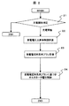
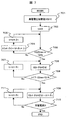
- 1 shows an overall processing flow according to an embodiment of the present invention.
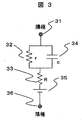
- the storage battery approximate circuit which makes one Embodiment of this invention is shown.
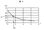
- An overview and a solution of f (x) forming an embodiment of the present invention are shown.
- the power generation voltage time series plan setting method which constitutes one embodiment of the present invention is shown.
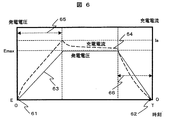
- the power generation voltage and charging current time series example 1 which constitutes one embodiment of the present invention is shown.
- the power generation voltage time series calculation which makes one Embodiment of this invention is shown.
- the power generation voltage time series calculation in the case of lowering the maximum voltage that constitutes an embodiment of the present invention is shown.
- the example 2 of the power generation voltage time series which forms one embodiment of the present invention is shown.
- a table example of c, r, and R is shown.
- the present embodiment relates to a technique of a charging method using an alternator (generator) of a storage battery in a moving body.
- a storage battery can be approximated by a circuit in which a capacitor component is connected in series to a constant voltage source, a charging current corresponding to the rate of change of the generated voltage flows.
- the alternator is a torque load corresponding to the current. For this reason, when the generated voltage is increased according to the deceleration, the torque of the alternator according to the deceleration of the moving body is generated, and the deceleration regeneration without any sense of incongruity is realized for the driver.
- the embodiment described below has been made in view of such circumstances, and provides a method of setting the voltage of an alternator that keeps the charging current to the storage battery within a specified value at any speed change.
- the regeneration efficiency is improved. Moreover, since a large current does not flow, heat generation of the storage battery is suppressed, and deterioration of the storage battery is suppressed. Furthermore, by temporarily raising the power generation voltage within a range in which the heat generation of the storage battery is suppressed, effects such as an increase in regenerative charge of the storage battery and an improvement in regeneration efficiency can be obtained.
- This alternator power generation voltage control method starts the alternator when the mobile unit is either decelerated or the storage battery charge level is low, so that a large current does not flow to the storage battery at the time of startup.
- an upper limit is set for the rate of increase in power generation voltage.
- FIG. 1 shows the configuration of an alternator voltage control method according to an embodiment of the present invention.
- This method is realized by software that runs in a controller in a moving object (car, train).
- This controller is a function in the engine controller when directly connected to the storage battery or when the engine controller is present in the moving body.
- the storage battery 10, alternator (generator) 11, ammeter 12, voltmeter 13, thermometer 14, internal resistance / capacity estimation unit 15, charge amount estimation unit 16, charge timing determination unit 17, generation voltage increase rate It comprises a limiting unit 18 and a generated voltage control unit 19.
- the internal resistance / capacity estimating unit 15, the charge amount estimating unit 16, the charging timing determining unit 17, the generated voltage increase rate limiting unit 18, and the generated voltage control unit 19 are software in the controller. Details of each part and each device will be described later.
- the storage battery 10 is a lead storage battery, a lithium battery, or a nickel metal hydride battery.
- the alternator is a generator connected to an axle of a moving body or an engine, and the generated voltage is controlled by a field current or a DC-DC converter.
- As an alternator realizing method there is a method of setting a generated voltage by controlling a field current as disclosed in Japanese Patent Application Laid-Open No. 60-102826. As an ammeter, you may use the device and method which calculate an electric current based on magnetic flux, after measuring magnetic flux with a non-contact-type device.
- step 21 the start of charging the storage battery is determined and determined (charging timing determination unit 17).
- the charging start condition is that the mobile body starts decelerating or the charge amount of the storage battery is equal to or less than the threshold value, and the process of step 22 is performed.
- the charge amount is estimated by the charge amount estimation unit 16.
- a method for estimating the charge amount a method is used in which the initial charge amount is estimated by measuring the terminal voltage of the storage battery before the moving body is started, and thereafter, the charge amount is estimated momentarily from the integrated value of the storage battery current.
- a method of predicting the charging amount from time to time based on a predetermined charging current at the time of charging and a discharging current at the time of discharging may be used.
- the storage battery is a lead storage battery
- a method for predicting the charge amount by using a sulfuric acid hydrometer attached to the storage battery may be used.
- the charge termination condition is when deceleration ends or when the storage battery charge amount is equal to or greater than a threshold value. Otherwise, the process ends without charging. Even if this program ends, the program is restarted periodically (for example, every second).
- step 22 the generated voltage increase rate limit is calculated.
- the power generation voltage increase rate limiting unit 18 in FIG. 1 calculates the limit of the power generation voltage increase rate based on the separately estimated time constant of the storage battery. Details of this processing will be described later.
- step 23 a power generation voltage time series plan is calculated based on the charging end timing and the power generation voltage increase rate. This is performed by the generated voltage control unit 19 of FIG. Details of this processing will be described later.
- step 24 the alternator is controlled according to the generation voltage time-series plan from the start to the end of charging. This is performed by the generated voltage control unit 19 of FIG. Although this program is stopped after completion, the program is restarted periodically (for example, every 1 second) even if this program ends.
- the power generation voltage increase rate is calculated based on the internal resistances r and R and the capacity C during charging estimated by the internal resistance / capacity estimation unit 15 in FIG.
- FIG. 3 shows an approximate equivalent circuit of the storage battery.
- the storage battery includes a voltage source 31 as a base, a charging resistor R32, a charging resistor r33, and a polarization capacitor c34.
- the calculation method of r, R, and C will be described later. From the circuit of FIG. 3, when the storage battery terminal voltage (generated voltage) is V and the current I is charged to the storage battery, Equation 1 is established.
- Equation 2 Voltage of the voltage source 31 serving as a base
- the charging current is expressed by Equation 1 and Equation 2 as Equation 3.
- the ramp response of the charging current response for increasing the current at a constant rate of increase from 0 [A]
- the generated voltage is set to a constant voltage
- the charging current thereafter decreases from Equation 1.
- the current when the lamp response is terminated at t0 that is, the maximum value Imax of the charging current is expressed by Equation 4 based on Equation 3.
- the maximum value Imax of the charging current expressed by Equation 4 may be set to Ia.
- Equation 5 f (x) is held in a table or numerically solved (for example, a known bisection method is used).
- Equation 4 shows an overview of f (x) obtained numerically and the relationship between x and Equation 5.
- a solution x42 of 1.6 is obtained from the value of f (x) of 41 in the figure.
- a fixed value of x 1 may be used.
- ⁇ obtained above may be used, but since it is calculated only by the battery, a method of setting the power generation voltage increase rate ⁇ in consideration of another factor will be described below.
- the alternator torque increase by alternator power generation is set to a torque reduction rate ⁇ or less that affects the alternator by deceleration.
- the torque reduction rate ⁇ is calculated as “ ⁇ / moving body tire diameter ⁇ moving body gear ratio” ( ⁇ is the deceleration of the moving body).
- the current of the alternator is proportional to the torque of the alternator. Therefore, the rate of increase of the alternator current is determined by multiplying ⁇ by a constant of constant ⁇ between the current of the alternator and torque ( ⁇ is a function of the rotational speed of the alternator). From this current increase rate, the power generation voltage increase rate ⁇ can be calculated. This calculation will be described below.
- the generated voltage time series is determined as Equation 7 by solving the differential equation of Equation 1.
- R ⁇ E / cr (constant value) that is the lower limit value of Equation 8 may be set to ⁇ instead of Equation 8.
- ⁇ 0.5 [V / s] is used.
- the smallest value may be selected from the ⁇ calculated by the equation 6, the ⁇ calculated by the equation 8 according to the deceleration, and the ⁇ determined by the light brightening.
- the alternator torque increase rate has an upper limit value ⁇ . If the alternator torque fluctuation larger than the engine torque increase rate upper limit ⁇ occurs, the engine may be stopped. Therefore, the alternator torque increase due to alternator power generation is set to the increase rate ( ⁇ ) or less.
- the calculation of ⁇ in this case can be similarly calculated as Equation 8.
- the smallest value may be selected from the ⁇ calculated in Equation 6, the ⁇ calculated in Equation 8 based on the above-mentioned upper limit of the engine torque increase rate, and the ⁇ determined by the light brightening.
- the power generation voltage may be changed to be equal to or less than this value.
- the generated voltage is controlled with the target value of the charging current as the current upper limit Ia.
- the alternator charging voltage may be obtained numerically by the differential equation of Formula 1, or the generated voltage may be updated by a value proportional to ⁇ Ia-current charging current ⁇ (Ia is set in advance) Maximum charging current (details are described later).
- the amount of change in power generation voltage (dV / dt) in this case is represented by Equation 9.
- Equation 1 may be solved by the Euler method.
- Equation 10 the value of the power generation voltage reduction rate -A is set in accordance with Equation 10 using ⁇ (derived from Equation 1).
- A 0.5 [V / s]
- the generation voltage time-series plan determination method in the generation voltage limiting unit 19 will be described with reference to FIG.
- the generation voltage time series plan first, at step 51, the upper limit Ia of the charging current is determined.
- an upper limit Emax of the generated voltage is determined. How to determine Emax will be described later. Here, Emax may be lowered in the middle depending on the heat generation state of the storage battery and the heat generation state of the alternator. Details will be described later.
- step 53 the open voltage of the storage battery (the voltage of the storage battery at 0 charging current) is determined. This measures the storage battery voltage at the time of current 0 [A] before charging with the voltmeter 13 of FIG.
- a time T until the end of charging is obtained.
- step 55 the generation voltage time series is calculated from the generation voltage increase rate ⁇ and the generation voltage decrease rate -A.
- the start time is started and the time for stopping the increase in the generated voltage is determined from the generated voltage increase rate ⁇ .
- the generation voltage decrease start time is calculated from the end time.
- FIG. 6 shows a generated voltage waveform 63 (solid line) and a charging current waveform 64 (broken line) from the time of charging start 61 to the time of charging end 62.
- the power generation voltage increase rate is ⁇ .
- the power generation voltage decrease rate is set to ⁇ A in 66 from the start of the generation voltage decrease to the end of the charge so that the current becomes zero at the end of the charge.
- the generation voltage decrease start time is T- (Emax-E) / A.
- the generated voltage may be adjusted while monitoring the charging current. This flow will be described with reference to the flowchart of FIG.
- step 701 the power generation voltage of the alternator is set to E (storage battery voltage at 0 charging current).
- step 702 the timer time t is set to zero.
- step 703 it is determined whether the current alternator power generation voltage V becomes the maximum voltage Emax or the charging current I becomes the current upper limit Ia. If the generated voltage V ⁇ the maximum voltage Emax or the charging current I ⁇ the current upper limit Ia, the generated voltage is held constant (step 706). If this condition is not satisfied, the generated voltage is increased by ⁇ ⁇ ⁇ t ( ⁇ t is a time step, for example, 10 ms) (step 704), the time is advanced by ⁇ t (705), and the determination of step 703 is made. Do.
- step 708 it is determined in step 708 whether the generation voltage decrease start time is reached. If it is the generation voltage decrease start time, the process proceeds to step 709. If it is not the generation voltage decrease start time, the time is advanced by ⁇ t in step 707.
- step 709 the generated voltage is reduced by a decrease rate -A. Thereafter, in step 710, it is determined whether or not the charging current is zero. If the charging current is not 0, the time is advanced by ⁇ t in step 711. If the charging current is 0, the process is terminated.
- the rate of increase in the generated voltage is assumed to be ⁇ , but the amount of change in generated voltage that is min ⁇ , constant ⁇ (Ia ⁇ charge current) ⁇ of the above-described formula 9 may be used.
- step 81 the current storage battery temperature is measured.
- step 82 the temperature of the alternator is measured.
- step 83 the battery battery temperature increase rate is calculated from the time difference of the battery temperature.
- step 84 the alternator temperature increase rate is calculated from the time difference of the alternator temperature.
- step 85 when the temperature rise estimate “temperature rise rate ⁇ (T ⁇ current time)” of the alternator or the storage battery becomes higher than a preset temperature (for example, 45 ° C. or engine room temperature) by the end of charging,
- step 86 Emax is lowered by ⁇ Emax.
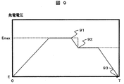
- the generated voltage is decreased by ⁇ Emax in step 86, the generated voltage is decreased at the generated voltage decrease rate -A. The voltage at this time corresponds to the operation of lowering the generated voltage 91 in FIG.
- alternator temperature determination in steps 82 and 84 and step 85 is omitted.
- step 87 is a condition that the charging current becomes zero at time T when the timing for decreasing the generated voltage has been reached, that is, when the generated voltage starts to decrease at the generated voltage decrease rate -A from the current time. It is.
- step 87 After the termination condition of step 87 is satisfied, the generated voltage is decreased at step 88 with the generated voltage decrease rate -A until the charging current becomes 0 (93 in FIG. 9).
- the generated voltage is determined from the withstand voltage of the electronic device connected to the alternator (for example, 15V).
- any one of a method of obtaining from a charging current at the previous charging, a generated voltage waveform, and a method of determining by referring to a table based on the current charge amount and temperature is used. If the configuration does not have an ammeter, a method is used in which the charge amount is estimated by the generated voltage and temperature, and the temperature and charge amount are determined by referring to a table. Each will be described below.
- c, r, and R are obtained from the time series data of the charging current and the generated voltage.
- V (s) obtained by Fourier-transforming ⁇ terminal voltage of storage battery ⁇ terminal voltage at storage battery charging current 0 ⁇ is calculated, and then I (s) obtained by Fourier-transforming the charging current is calculated.
- S indicates s of the Laplace operator.
- 1 / z (s) s is subjected to inverse Fourier transform to obtain a charging current waveform when the generated voltage is assumed to be a step response of 1V.
- the Fourier transform numerical release of the fast Fourier transform may be used (references “Masahiko Sagawa, Hitoshi Takaya: Fast Fourier transform and its application, Shosodo”).
- Equation 1 Since the initial value of the charging current is calculated as 1 / R, R is obtained from the initial charging current of the generated voltage step response. Similarly, since the steady value of the charging current of the generated voltage step response is calculated as 1 / (R + r) by solving Equation 1, the value of r can be obtained. Next, the current is an exponential function exp ( ⁇ t / k), and the constant k is expressed as Equation 11 from Equation 1 below. Further, k can be obtained by taking the logarithm of “charging current of power generation voltage step response ⁇ (Emax ⁇ E) / (R + r)”.
- the values of R, r, and C are calculated at the charging timing and used for the next charging. In the case immediately after replacing the storage battery, an estimated value based on the table described below is used.
- the c, r, and R tables that are tabulated for each storage battery charge amount, deterioration degree, and temperature are referred to based on the charge amount, deterioration degree, and temperature.
- An example of this table is shown in FIG.
- the charge amount is estimated by the charge amount estimation unit 14 of FIG.
- a thermometer 14 is used for the temperature.
- the SOC 101 in FIG. 10 indicates a ratio [%] obtained by dividing the charge amount [Ah] by the catalog capacity [Ah] of the storage battery, and indicates a value estimated by the charge amount estimated amount 16 in FIG. SOH102 in FIG.
- FIG. 10 shows a deterioration degree and shows the ratio [%] which divided the capacity
- a temperature SOC table prepared for each SOH is prepared.
- the SOC is 40%
- the SOH is 100%
- a table corresponding to the SOH 100% is selected, and the values of c, r, and R described in the column 103 in FIG. Use.
- the SOC 50% column does not exist as an example, but estimation is performed by interpolation from values of SOC 40% and 60%.
- the SOH estimation method is obtained from the value of the discharge resistance obtained from the correlation between the storage battery current and the storage battery voltage during discharge.
- the discharge resistance can be estimated by the amount of decrease in the storage battery voltage when starting the engine by cranking (in the case of a moving body with an engine, when the engine is started by the storage battery). good.
- the amount of decrease in storage battery voltage ⁇ constant (the constant is a preset value).
- the charging start timing may be started when the battery is not fully charged and the temperature of the storage battery is low. This is because when the temperature of the storage battery is low, the value of the charging resistance is generally large and the charging efficiency is lowered. At this time, control of the generated voltage is started, and the temperature of the storage battery is raised. The termination condition is that the battery is fully charged or the temperature of the storage battery reaches the ambient temperature of the storage battery.
- this alternator power generation voltage control method performs control so that the charging current of the storage battery becomes zero when charging / discharging is not performed.
- Ia in Equation 11 is set to 0 and the generated voltage is changed.
Landscapes
- Engineering & Computer Science (AREA)
- Power Engineering (AREA)
- Control Of Eletrric Generators (AREA)
- Control Of Charge By Means Of Generators (AREA)
Abstract
蓄電池に大電流を流さない、または異常発熱をしないよう、蓄電池への充電電圧上昇率に制限をかける制御を行う。 充電の開始と終了のタイミングを判定する充電タイミング決定部と、蓄電池のパラメータを推定する蓄電池パラメータ推定部と、蓄電池の充電状態を予測する充電状態推定部と、オルタネータの発電電圧上昇率を決定する発電電圧上昇率決定部と、オルタネータの発電電圧を制御する発電電圧制御部と、を有し、移動体の蓄電池へ充電を開始する際に、オルタネータの発電電圧を上昇させるにあたり、予め推定した蓄電池のパラメータに基づいて、発電電圧上昇率に上限を設ける。
Description
本発明は、オルタネータの制御装置及び制御方法に関する。
従来、オルタネータ(発電機)による発電電圧の設定方法として、移動体の減速度に応じて発電電圧上昇率を設定する方法があった(例えば、特許文献1参照)。
従来技術において、移動体の減速度によりオルタネータの発電電圧を変化させた場合、減速度が大きい場合には急な電圧変化が起こる。蓄電池への充電電流は蓄電池端子電圧の変化率に応じた値となるため、瞬間的に蓄電池へ100[A]にも及ぶ電流が流れる。
この大電流によって、磁気飽和が起こりオルタネータの効率が悪くなって回生効率が下がる。また蓄電池に大電流が流れた場合、電流の二乗に比例する熱が発生するため、この熱により電解液の蒸発に繋がり、電極が熱で劣化する原因にもなる。しかし、従来の技術ではこの点について十分に配慮されていなかった。
本発明は、移動体の減速度が大きい場合に生じるオルタネータの大電流に起因する問題点を解決する。
本発明は、一つは、移動体に搭載されるオルタネータの制御装置であって、オルタネータから移動体の蓄電池への充電の開始と終了のタイミングを判定する充電タイミング決定部と、蓄電池のパラメータを推定する蓄電池パラメータ推定部と、蓄電池の充電状態を予測する充電状態推定部と、オルタネータの発電電圧上昇率を決定する発電電圧上昇率決定部と、オルタネータの発電電圧を制御する発電電圧制御部と、を有し、蓄電池へ充電を開始する際に、オルタネータの発電電圧を上昇させるにあたり、予め推定した蓄電池のパラメータに基づいて、前記発電電圧上昇率に上限を設けたことを特徴とする。
もう一つは、移動体に搭載されるオルタネータの制御方法であって、オルタネータから移動体の蓄電池への充電の開始と終了のタイミングを判定し、蓄電池のパラメータを推定し、蓄電池の充電状態を予測し、オルタネータの発電電圧上昇率を決定し、蓄電池へ充電を開始する際に、オルタネータの発電電圧を上昇させるにあたり、予め推定した蓄電池のパラメータに基づいて、前記発電電圧上昇率に上限を設けてオルタネータの発電電圧を制御することを特徴とする。
本発明によれば、移動体の減速度が大きい場合に生じるオルタネータの大電流に起因する問題点を解決することができる。
以下、本発明の実施形態を説明する。本実施形態は、移動体における蓄電池のオルタネータ(発電機)による充電方法の技術に関するものである。
蓄電池は経験的に、定電圧源にコンデンサ成分が直列に接続された回路と近似できるため、発電電圧の変化率に応じた充電電流が流れる。また、オルタネータは電流に応じたトルク負荷となる。このため、減速度に応じて発電電圧を上昇させると、移動体の減速に応じたオルタネータのトルクが発生し、ドライバにとって違和感の無い減速回生が実現する。
減速度によりオルタネータの発電電圧を変化させた場合、減速度が大きい場合には急な電圧変化が起こる。前述したように、蓄電池への充電電流は蓄電池端子電圧の変化率に応じた値となるため、瞬間的に蓄電池へ100[A]にも及ぶ電流が流れる。そして、オルタネータが蓄電池へ大電流を流すことにより、磁気飽和が起こりオルタの効率が悪くなって回生効率が下がる課題がある。
また蓄電池に大電流が流れた場合、電流の二乗に比例する熱が発生するため、この熱により電解液の蒸発に繋がり、電極が熱で劣化する原因にもなる。
以下に示す実施形態は、このような事情を鑑みなされたもので、如何なる速度変化においても蓄電池への充電電流を規定値以内にするオルタネータの電圧を設定する方法を提供する。
本実施形態によれば、蓄電池への最大充電電流をオルタネータの効率が悪くならない範囲に抑えるため、回生効率が向上する。また大電流が流れないため、蓄電池の熱発生が抑えられ、蓄電池の劣化が抑えられる。更には、蓄電池の発熱を抑える範囲にて一時的に発電電圧を上げることにより、蓄電池の回生電荷が増え、回生効率が向上するなどの効果が得られる。
本オルタネータ発電電圧制御方法は、移動体において、減速または蓄電池の充電量が低くなったかの何れかの場合に、オルタネータを起動し、その起動の際に蓄電池へ大電流を流さないように、オルタネータの発電電圧上昇率に上限を設ける方法である。
図1に本発明の一実施形態をなすオルタネータ電圧制御方法の構成を示す。本方法は、移動体(車,電車)内のコントローラ内で動くソフトウエアで実現される。本コントローラは、蓄電池に直結するか、移動体にエンジンコントローラが存在する場合には、エンジンコントローラ内の一機能となる。
本方法では、蓄電池10,オルタネータ(発電機)11,電流計12,電圧計13,温度計14,内部抵抗・容量推定部15,充電量推定部16,充電タイミング決定部17,発電電圧上昇率制限部18,発電電圧制御部19から構成される。内部抵抗・容量推定部15,充電量推定部16,充電タイミング決定部17,発電電圧上昇率制限部18,発電電圧制御部19はコントローラ内のソフトウエアである。各部,各装置の詳細については後述する。
蓄電池10は、鉛蓄電池,リチウム電池,ニッケル水素電池が対象となる。オルタネータは、移動体の車軸、またはエンジンに接続されている発電機であり、発電電圧は界磁電流、またはDC-DCコンバータによりコントロールされる。オルタネータの一実現方法としては特開昭60-102826号公報に示される、界磁電流を制御して発電電圧を設定する方法がある。電流計としては、非接触式のデバイスで磁束を計測した後に、磁束を元に電流を計算するデバイスと方法を用いてもよい。
続いて、本方法の処理を、図2を用いて説明する。まず本処理では、ステップ21において、蓄電池への充電開始を判定決定する(充電タイミング決定部17)。充電開始条件は移動体が減速に入るかまたは蓄電池の充電量が閾値以下になった場合とし、ステップ22の処理を行う。充電量は充電量推定部16にて推定する。この充電量の推定方法として、移動体が始動する前の蓄電池の端子電圧を測って初期の充電量を推定し、その後には蓄電池電流の積算値より充電量を時々刻々推定する方法を用いる。ここで、電流計12が存在しない場合には、予め決めた充電時の充電電流,放電時の放電電流により充電量を時々刻々予測する方法を用いても良い。また蓄電池が鉛蓄電池の場合には、別途蓄電池に取り付けた硫酸比重計により充電量を予測する方法を用いても良い。
充電終了条件は、減速終了か、蓄電池の充電量が閾値以上となった場合とする。それ以外では充電を実施せずに終了する。本プログラムは終了しても定期的(例として1秒おき)にプログラムを再起動する。
次に、充電開始の場合、ステップ22において、発電電圧上昇率制限を計算する。本処理は、蓄電池への充電電流を制限するために、図1の発電電圧上昇率制限部18にて、別途推定した蓄電池の時定数により発電電圧上昇率の制限を計算する。本処理の詳細については後述する。
次に、ステップ23において、充電終了タイミングと、発電電圧上昇率に基づいて、発電電圧時系列プランを計算する。これは、図1の発電電圧制御部19にて行われる。この処理の詳細については後述する。
最後に、ステップ24において、充電開始から終了まで、オルタネータを発電電圧時系列プランに従い制御する。これは、図1の発電電圧制御部19にて行われる。終了後は本プログラムを停止するが、本プログラムは終了しても定期的(例として1秒おき)にプログラムを再起動する。
次に、ステップ22における発電電圧上昇率制限計算の詳細について説明する。発電電圧上昇率計算は、図1の内部抵抗・容量推定部15で推定した、充電時の内部抵抗r,R,容量Cを元に計算する。図3に蓄電池の近似等価回路を示す。蓄電池はベースとなる電圧源31,充電抵抗R32,充電抵抗r33,分極容量c34から構成される。r,R,Cの計算方法については後述する。図3の回路より、蓄電池端子電圧(発電電圧)をV、蓄電池へ充電される電流Iとすると、数1が成立する。
(数1)
V-E+cr×dV/dt=(r+R)I+crR×dI/dt
E:ベースとなる電圧源31の電圧
ここで、数1の微分方程式の時定数τを数2とする。
(数2)
τ=cr′
τ:時定数
r′=r×R/(r+R)
r′:rとRの合成抵抗(蓄電池を低電圧源に接続した場合の内部抵抗)
充電電流は、充電電流初期条件としてI(0)=0、発電電圧上昇率λ(λ=dV/dt)とした場合、数1,数2より数3と示される。
(数3)
I(t)=λ×(cr-τ)×{1-exp(-t/τ)}/(r+R)+
λ×t/(r+R)
t:時間(充電開始を0)
数3で、充電電流のランプ応答(0[A]より一定の上昇率で電流を上昇させる応答)を終了させ、発電電圧を一定電圧にしたときには、数1よりその後の充電電流が低下する。このため、t0にてランプ応答を終了させたときの電流、即ち充電電流の最大値Imaxは、数3を元に、数4で示される。
(数4)
Imax=I∞×{f(x)×r/R+1}
I∞=(E∞-E)/(r+R):発電電圧一定にした場合の最終充電電流
f(x)={1-exp(-x)}/x
x=t0/τ
E∞=最終発電電圧
λ=(E∞-E)/t0
E:初期蓄電池電圧。充電開始直前(電流0時)の蓄電池端子電圧
ここで、充電電流を許容充電電流Ia内に抑えるためには、数4で表される充電電流の最大値ImaxをIaとすれば良い。このため、数5の方程式の解x(時定数補正倍率)を求めた後、数6より発電電圧上昇率の上限λが計算される。
(数5)
f(x)=R/r×(Ia/I∞-1)={1-exp(-x)}/x
x:時定数補正倍率
(数6)
λ=(E∞-初期電圧)/(x×τ)
次に、数5の方程式を求める方法について述べる。数5の解を求めるには、f(x)をテーブルで持たせるかまたは、数値的に解く(例えば知られている二分法を用いる)。数値的に求めたf(x)の概観と、xと数5の関係を図4に示す。例として、数5の右辺が0.5であった場合、図的には41のf(x)の値より、解x42である1.6が求められる。ここで、解xを求めることが、コントローラの処理性能より困難である場合には、x=1の固定値を使用しても良い。
ここで、数2で求めたτが2秒、端子初期電圧が13[V]、E∞=14[v]としたとき、数5,6より発電電圧上昇率λは0.3125[V/s]と計算される。
上記で求めたλを用いても良いが、バッテリのみにより計算されたものであるため、以下、別要因を考慮した発電電圧上昇率λを設定する方法について述べる。
移動体が減速を開始した場合の充電開始では、減速より大きなオルタネータのトルクが発生すると、移動体の乗り心地に影響を及ぼす。このため、オルタ発電によるオルタトルクアップを、減速によりオルタネータへ影響するトルク減少率η以下とする。トルク減少率ηは、「α/移動体のタイヤ径×移動体ギア比」と計算される(αは移動体の減速度)。
また、オルタネータの電流はオルタネータのトルクに比例する。このため、ηに、オルタネータの電流とトルクの比例定数κ(κはオルタネータの回転数の関数)をかけて、オルタネータ電流上昇率が決定される。この電流上昇率より、発電電圧上昇率λが計算できる。この計算を以下説明する。数1の微分方程式を解くことにより数7として発電電圧時系列が決定される。
(数7)
V(t)=exp(-t/cr)×{E+η×κ×c×r×r}
+(R+r)I(t)-η×κ×c×r×r
E:開放時の蓄電池電圧
η:トルク減少率[Nm/s]
κ:オルタネータのトルク-電流比例定数[A/Nm]
I(t)=η×κ×t
数7を時間微分すると数8となるため、数8を発電電圧上昇率λとする。このとき、発電電圧上昇率λは時間と共に変化することになる。更には、数8の代わりに、数8の下限値であるRηκ-E/cr(一定値)をλとしても良い。
(数8)
λ=(R+r)ηκ-exp(-t/cr)×{E+η×κ×c×r×r}/cr
ライトを点灯させた場合には、ライトの増光が人間に気づかない定数とする。この値の例として、λ=0.5[V/s]を用いる。
ここで、数6で計算されたλ、減速度に応じて数8で計算されたλ、ライトの増光により決定されたλの中で最も小さな値を選んでも良い。
次に、充電開始が蓄電池の充電不足であった場合を説明する。
この場合、オルタネータの発電開始により、エンジンは発電に要するトルク分だけトルクを上昇させる必要がある。ここで、エンジンのトルクを上昇させる際には、エンジンへの空気量を増やすが、空気の移動には遅れがあるため、エンジントルク増加率には上限値ηがある。このエンジントルク増加率上限ηより大きなオルタネータトルク変動が発生するとエンジンが停止する恐れがあるため、オルタ発電によるオルタトルクアップをこの増加率(η)以下とする。この場合のλの計算は、同様に、数8として計算できる。
ここで、数6で計算されたλ、上記のエンジントルク増加率アップ上限を元に数8で計算されたλ、ライトの増光により決定されたλの中で最も小さな値を選んでも良い。
次に、λは発電電圧上昇率の上限値であるため、この値以下となるように発電電圧を変化させても良い。具体的には、充電電流の目標値を電流上限Iaとして発電電圧を制御する。具体的には数1の微分方程式により、オルタネータ充電電圧を数値的に求めるか、または{Ia-現在の充電電流}に比例した値だけ発電電圧を更新させても良い(Iaは、予め設定した最大充電電流。詳細は後述。)。この場合の発電電圧変化量(dV/dt)を数9とする。数値的に求める方法としては、例として数1をオイラー法にて解いても良い。
(数9)
発電電圧変化量=min(λ,{Ia-I(t)}×定数)
Ia:最大充電電流
λ:発電電圧上昇率上限
定数:予め決めた定数
次に、充電終了時の発電電圧減少率(電圧を下げる場合の上限設定)について述べる。この場合には、充電終了によりオルタネータのトルクが0になるため、エンジンとしてはオルタネータのトルク負荷分を減少させる。従い、エンジンコントロールとしてはエンジンへの空気を減らすことになる。ここで空気の移動には遅れがあるため、エンジントルクの減少率には下限が存在することになる。この下限値の絶対値をηとする。そして、発電電圧減少率-Aをηにより数10で値を設定する(数1により導かれる)。
(数10)
-A=-(R+r)ηκ+exp(-t/cr)×{E+η×κ×c×r×r}/cr
η:トルク減少率上限値[Nm/s]
κ:オルタネータのトルク-電流比例定数[As/Nm]
ライトを点灯させた場合には、ライトの減光が人間に気づかない発電電圧減少率-Aを設定する(例としてA=0.5[V/s])。
次に、発電電圧制限部19における発電電圧時系列のプラン決定方法を図5で述べる。発電電圧時系列プランとしては、まずステップ51で充電電流の上限Iaを決定する。上限充電電流Iaはオルタネータの効率を保てる範囲と、オルタネータに接続されている他の電子機器の電流需要を元に、予め値を設定する(例としてオルタネータの効率を保てる範囲を60[A]、電子機器の電流需要が40[A]の場合、Ia=60-40=20[A])。続いて、ステップ52で発電電圧の上限Emaxを決める。Emaxの決め方は後述する。ここで、Emaxは、蓄電池の発熱状態、オルタネータの発熱状態により途中で値を下げても良い。詳細については後述する。
次に、ステップ53で蓄電池の開放電圧(充電電流0時の蓄電池の電圧)を決定する。これは、充電前の電流0[A]時における蓄電池電圧を図1の電圧計13により測定する。
次に、ステップ54で、充電終了時まので時間Tを得る。減速時における充電終了時間は、減速終了を予測して決定する。具体的には、車速により車の平均減速度を予測し、現在の速度よりTを決定する。減速時以外の充電では、現在の充電量とターゲットとなる充電量より決定する。この場合は「T=(ターゲット充電量-現在の充電量)/I∞」とする(I∞は数4で計算される値)。
最後にステップ55で発電電圧上昇率λ、発電電圧減少率-Aより発電電圧時系列を計算する。この計算としては、開始時間をスタートとして発電電圧上昇率λより、発電電圧の上昇をストップさせる時間を決定する。次に、終了時間より、発電電圧減少開始時間を計算する。この例を、図6の発電電圧波形を用いて説明する。図6は、充電開始61の時間から、充電終了62の時間までの発電電圧波形63(実線)と充電電流波形64(破線)を示す。充電開始から充電電流が上限値Iaまでの間65では、発電電圧上昇率をλとする。最後に、充電終了時に電流が0となるように、発電電圧減少開始から充電終了時までの間66では発電電圧減少率を-Aとする。発電電圧減少開始時刻はT-(Emax-E)/Aとなる。
以上、予め発電電圧を決定する方法を示したが、充電電流を監視しながら発電電圧を調整してもよい。この流れを図7のフロチャートを用いて説明する。
初めに、ステップ701にてオルタネータの発電電圧をE(充電電流0時の蓄電池電圧)とする。次にステップ702にてタイマー時刻tを0に設定する。
次にステップ703にて現在のオルタネータ発電電圧Vが最大電圧Emaxになるか、充電電流Iが電流上限Iaになるかを判定する。もし、発電電圧V≧最大電圧Emaxかまたは、充電電流I≧電流上限Iaになった場合、発電電圧を一定に保持する(ステップ706)。もしこの条件を満たさない場合には、発電電圧をλ×δt(δtは時刻ステップ。例として10ms)だけ増加させ(ステップ704)、時刻をδtだけ進めた後(705)、ステップ703の判定を行う。
ステップ706の後ステップ708にて、発電電圧減少開始時刻かを判定する。もし、発電電圧減少開始時刻ならば、ステップ709へ処理を移す。もし、発電電圧減少開始時刻でなければ、ステップ707にて時刻をδtだけ進める。
ステップ709では、発電電圧を減少率-Aだけ小さくする。その後、ステップ710で充電電流が0かどうかを判定する。充電電流が0で無い場合には、ステップ711にて時刻をδtだけ進める。充電電流が0の場合、処理を終了させる。
図7では、発電電圧上昇率をλ一定としたが、前述した数9のmin{λ,定数×(Ia-充電電流)}となる発電電圧変化量を用いても良い。
次に、途中で最大電圧Emaxが途中で変化する場合を、図8のフロチャートと図9の発電電圧時系列を用いて説明する。これは、一時的に発電電圧を上昇させ回生効率を上げる場合に、オルタネータの熱または蓄電池の温度が危険レベルに達しないように監視するためである。もし、温度が予め設定された上限値に到達しそうな場合にEmaxを下げる。
まず、ステップ81において現在の蓄電池温度を計測する。次にステップ82においてオルタネータの温度を計測する。次にステップ83において、蓄電池温度の時間差分により蓄電池温度上昇率を計算する。次にステップ84において、オルタネータ温度の時間差分によりオルタネータ温度上昇率を計算する。ステップ85において、充電終了までにオルタまたは蓄電池の温度上昇見積もり「温度上昇率×(T-現時刻)」が予め設定された温度(例として45℃。またはエンジンルーム温度)より大きくなる場合に、ステップ86にてEmaxをΔEmaxだけ下げる。ここで、ステップ86にてΔEmaxだけ発電電圧を下げる場合には、発電電圧減少率-Aにて発電電圧を下げる。このときの電圧は、図9の発電電圧91を発電電圧92まで下げる動作に対応する。
なお、オルタネータに温度計が無い場合には、ステップ82,84とステップ85のオルタネータ温度判定を省略する。
このステップ81からステップ86までの動作を、ステップ87の終了条件を満たすまで継続する。ステップ87の終了条件とは、発電電圧を減少させるタイミングに到達したかどうか、即ち現時刻から発電電圧減少率-Aで発電電圧を減少させ始めたとき、時刻Tにて充電電流0となる条件である。
ステップ87の終了条件が成立した後には、ステップ88にて発電電圧減少率-Aにて、充電電流が0になるまで(図9では93)発電電圧を減少させる。
次に、発電電圧の上限Emaxの初期値設定方法について述べる。発電電圧は、オルタネータに接続されている電子機器の耐圧より決定する(例として15V)。
次に、c,r,Rの推定方法について述べる。推定には、前回の充電時の充電電流、発電電圧波形により求める方法、現在の充電量と温度によりテーブルを参照して決める方法の何れかの方法を使う。もし、電流計が無い構成であるならば、充電量を発電電圧と温度で推定し、温度と充電量をテーブル参照して決める方法を採用する。以下、それぞれについて述べる。
電流計と電圧計が付加されている場合には、c,r,Rを充電電流と発電電圧の時系列データより求める。求め方としては、初めに{蓄電池の端子電圧-蓄電池の充電電流0時の端子電圧}をフーリエ変換したV(s)を計算し、次に充電電流をフーリエ変換したI(s)を計算する(sとはラプラス演算子のsを示す)。次にz(s)=V(s)/I(s)として内部インピーダンスz(s)を求める。求めたz(s)より、1/z(s)sをフーリエ逆変換することにより、発電電圧が1Vのステップ応答と仮定した場合の充電電流波形を求めることができる。フーリエ変換としては高速フーリエ変換の数値解放を用いても良い(参考文献「佐川雅彦,貴家仁志:高速フーリエ変換とその応用、昭晃堂」)。
数1を解くことにより、充電電流の初期値が1/Rと計算されるため、発電電圧ステップ応答の初期充電電流よりRが求められる。同様に、発電電圧ステップ応答の充電電流の定常値は、数1を解くことにより1/(R+r)と計算されるため、rの値を求めることができる。次に、次に電流は指数関数exp(-t/k)であり、定数kは、微分方程式数1より数11と示される。また、「発電電圧ステップ応答の充電電流-(Emax-E)/(R+r)」の対数を取ることにより、kを求めることができる。
(数11)
k=c×r′
r′=r×R/(r+R)
r′:rとRの合成抵抗(蓄電池を低電圧源に接続した場合の内部抵抗)
数11とkよりcを求めることができる。このR,r,Cの値は、充電するタイミングにおいて計算し、次回の充電で使用する。蓄電池を交換した直後の場合には、次に述べるテーブルによる推定値を用いる。
(数11)
k=c×r′
r′=r×R/(r+R)
r′:rとRの合成抵抗(蓄電池を低電圧源に接続した場合の内部抵抗)
数11とkよりcを求めることができる。このR,r,Cの値は、充電するタイミングにおいて計算し、次回の充電で使用する。蓄電池を交換した直後の場合には、次に述べるテーブルによる推定値を用いる。
次に、テーブルを用いてc,r,Rを求める方法について述べる。概要としては、蓄電池の充電量,劣化度,温度毎に集計されているc,r,Rのテーブルを、充電量,劣化度,温度を元に参照する。このテーブル例を図10に示す。充電量は、前述したように図1の充電量推定部14にて推定する。温度は、温度計14を使用する。図10におけるSOC101とは、充電量[Ah]を蓄電池のカタログ容量[Ah]で割った比率[%]を示し、図1の充電量推定量16にて推定した値を示す。図10におけるSOH102とは、劣化度を示し、現在使用できる蓄電池の容量をカタログ容量[Ah]で割った比率[%]を示す。図10ではSOH毎に用意された、温度SOC表を用意している。ここで、温度が40℃、SOCが40%、SOHが100%の場合には、SOH100%に対応する表を選び出し、図10の103の欄に記載されているc,r,Rの値を用いる。図10では、例としてSOC50%の欄が存在していないが、SOC40%と60%の値より補間して推定する。
SOHの推定方法は、放電時の蓄電池電流と蓄電池電圧の相関より求めた放電抵抗の値より求める。ここで、電流計が設置されていない場合には、クランキング(エンジンの有る移動体の場合、蓄電池によるエンジン始動時)にてエンジン始動の際、蓄電池電圧の降下量により放電抵抗を推定すれば良い。具体的な推定方法として、蓄電池電圧の降下量×定数とする(定数は予め設定した値とする)。
本オルタネータ発電電圧制御方法では、充電開始のタイミングを、満充電でなくかつ蓄電池の温度が低い場合に充電を開始しても良い。これは、蓄電池の温度が低い場合、一般的に充電抵抗の値が大きく、充電効率が下がるためである。このとき、発電電圧の制御を開始し、蓄電池の温度を上昇させる。この終了条件は、満充電になるかまたは、蓄電池の温度が、蓄電池の周囲気温に到達するまでとする。
最後に、本オルタネータ発電電圧制御方法は、充放電を行わない場合には、蓄電池の充電電流を0となるような制御を行う。この制御としては、数11のIaを0として、発電電圧を変化させる。
10…蓄電池、11…オルタネータ、12…電流計、13…電圧計、14…温度計,カーブ前警報,制動、15…内部抵抗・容量推定部、16…充電量推定部、17…充電タイミング決定部、18…発電電圧上昇率制限部、19…発電電圧制御部、21…充電開始判定、22…発電電圧上昇率制限計算、23…発電電圧時系列プラン計算、24…発電電圧制御、31…陽極、32…内部抵抗r、33…内部抵抗R、34…コンデンサc、35…ベース電圧、36…陰極、41…f(x)、42…解x、51…充電電流上限Ia決定、52…電圧上限Emax決定、53…蓄電池開放電圧E測定、54…充電終了時間T決定、55…発電電圧時系列計算、61…充電開始時刻、62…充電終了時刻、63…オルタネータ発電電圧時系列、64…充電電流、65…オルタネータ発電電圧上昇中区間、66…オルタネータ発電電圧減少中区間、81…蓄電池温度計測、82…オルタネータ温度計測、83…蓄電池温度上昇率計算、84…オルタネータ温度上昇率計算、85…最大電圧減少判定、86,88,709…発電電圧減少、87,708…発電電圧減少開始判定、91…最大電圧減少開始、92…最大電圧減少終了、93…充電終了、101…充電量(SOC)、102…劣化度(SOH)、103…SOC40%,温度40℃のときのR,r,C、701…発電電圧初期値設定、702…時刻初期化、703…発電電圧上昇停止判定、704…発電電圧上昇、705,707,711…時刻更新、706…発電電圧保持、710…充電終了判定
Claims (21)
- 移動体に搭載されるオルタネータの制御装置であって、
前記オルタネータから前記移動体の蓄電池への充電の開始と終了のタイミングを判定する充電タイミング決定部と、前記蓄電池のパラメータを推定する蓄電池パラメータ推定部と、前記蓄電池の充電状態を予測する充電状態推定部と、前記オルタネータの発電電圧上昇率を決定する発電電圧上昇率決定部と、前記オルタネータの発電電圧を制御する発電電圧制御部と、を有し、
前記蓄電池へ充電を開始する際に、前記オルタネータの発電電圧を上昇させるにあたり、予め推定した前記蓄電池のパラメータに基づいて、前記発電電圧上昇率に上限を設けたことを特徴とするオルタネータの制御装置。 - 請求項1記載のオルタネータの制御装置であって、
前記充電タイミング決定部は、充電開始のタイミングを、前記移動体の減速時、または前記蓄電池の充電量が許容値以下になった場合の何れかとするオルタネータの制御装置。 - 請求項1記載のオルタネータの制御装置であって、
前記蓄電池パラメータ推定部は、前記蓄電池の電圧と電流の時系列データにより、前記蓄電池のコンデンサ容量と抵抗を計算するオルタネータの制御装置。 - 請求項3記載のオルタネータの制御装置であって、
前記蓄電池パラメータ推定部は、前回の充電時における蓄電池の電圧と電流の時系列データから前記蓄電池のコンデンサ容量と抵抗を推定するオルタネータの制御装置。 - 請求項1記載のオルタネータの制御装置であって、
前記蓄電池パラメータ推定部は、予め集計した前記蓄電池のコンデンサ容量と抵抗のテーブルにより前記蓄電池のコンデンサ容量と抵抗を推定するオルタネータの制御装置。 - 請求項5記載のオルタネータの制御装置であって、
前記テーブルとして、温度と充電量毎に集計したテーブルを用いたオルタネータの制御装置。 - 請求項1記載のオルタネータの制御装置であって、
前記発電電圧上昇率の上限を、予め与えた前記蓄電池の最大許容充電電流、および前記蓄電池のコンデンサ容量と抵抗により計算するオルタネータの制御装置。 - 請求項7記載のオルタネータの制御装置であって、
前記発電電圧上昇率の上限値を、予め与えた最大発電電圧と初期蓄電池電圧との差を、蓄電池コンデンサと抵抗値で計算される時定数で割った値とするオルタネータの制御装置。 - 請求項8記載のオルタネータの制御装置であって、
前記時定数として、充電時の前記蓄電池を直流電圧源に繋いだと仮定した場合の前記蓄電池の内部抵抗とコンデンサの容量の積とするオルタネータの制御装置。 - 請求項9記載のオルタネータの制御装置であって、
前記時定数として、最大許容充電電流、最大発電電圧で充電したと仮定した場合に計算される定常的な充電電流、前記蓄電池の内部抵抗で計算される倍率で補正するオルタネータの制御装置。 - 請求項8記載のオルタネータの制御装置であって、
前記最大発電電圧の設定方法として、オルタネータに接続された電子機器の耐圧とするオルタネータの制御装置。 - 請求項8記載のオルタネータの制御装置であって、
前記最大発電電圧として、蓄電池の温度の上昇率と現在温度により、蓄電池の温度が充電終了までに、予め設定された最大温度以上または気温以上と予測される場合に、最大発電電圧を与えられた初期値より下げるオルタネータの制御装置。 - 請求項2記載のオルタネータの制御装置であって、
前記充電開始タイミングが移動体の減速時であった場合の発電電圧上昇率の上限として、移動体の減速度により計算される発電電圧上昇率と、予め与えた最大発電電圧と初期蓄電池電圧との差を、蓄電池コンデンサと抵抗値で計算される時定数で割って求めた発電電圧上昇率の上限の小さい方の値を発電電圧上昇率の上限とするオルタネータの制御装置。 - 請求項13記載のオルタネータの制御装置であって、
前記移動体の減速度により計算される発電電圧上昇率として、予め与えられた移動体のタイヤ径、ギア比と減速度によりエンジンのトルク減少率を計算し、次に、オイルタネータトルクと電流の換算係数をトルク減少率にかけて電流変化率を求め、電流変化率より発電電圧上昇率を計算するオルタネータの制御装置。 - 請求項2記載のオルタネータの制御装置であって、
充電開始タイミングが減速時以外の場合の発電電圧上昇率の上限として、発電開始により移動体のエンジントルクを増加させる時の増加率の上限により計算される発電電圧上昇率と、予め与えた最大発電電圧と初期蓄電池電圧との差を、蓄電池コンデンサと抵抗値で計算される時定数で割って求めた発電電圧上昇率の上限の小さい方の値を発電電圧上昇率の上限とするオルタネータの制御装置。 - 請求項15記載のオルタネータの制御装置であって、
前記エンジントルク増加率の上限で計算される発電電圧上昇率として、オルタネータトルクとオルタネータ発電電流の換算係数を、エンジントルク増加率の上限にかけて計算される電流変化率により、発電電圧上昇率を計算するオルタネータの制御装置。 - 請求項14記載のオルタネータの制御装置であって、
前記電流変化率から発電電圧上昇率を計算する方法として、予め与えられた蓄電池の回路方程式へ電流変化率を与えた時に得られる蓄電池の電圧時系列データにより、発電電圧上昇率を計算するオルタネータの制御装置。 - 請求項1記載のオルタネータの制御装置であって、
前記蓄電池の充放電を行わない場合には、前記蓄電池に流れる電流が0となるように発電電圧を制御するオルタネータの制御装置。 - 請求項13記載のオルタネータの制御装置であって、
前記発電電圧上昇率の上限として、オルタネータにライトが接続され、かつライトが点灯している場合には、予め設定した電圧上昇率により上限を設けるオルタネータの制御装置。 - 請求項1記載のオルタネータの制御装置であって、
前記充電開始のタイミングとして、前記蓄電池の充電量が満充電でなく、かつ前記蓄電池の温度が予め設定された温度より低い場合とするオルタネータの制御装置。 - 移動体に搭載されるオルタネータの制御方法であって、
前記オルタネータから前記移動体の蓄電池への充電の開始と終了のタイミングを判定し、蓄電池のパラメータを推定し、前記蓄電池の充電状態を予測し、前記オルタネータの発電電圧上昇率を決定し、前記蓄電池へ充電を開始する際に、前記オルタネータの発電電圧を上昇させるにあたり、予め推定した前記蓄電池のパラメータに基づいて、前記発電電圧上昇率に上限を設けて前記オルタネータの発電電圧を制御することを特徴とするオルタネータの制御方法。
Applications Claiming Priority (2)
| Application Number | Priority Date | Filing Date | Title |
|---|---|---|---|
| JP2009154521A JP5271831B2 (ja) | 2009-06-30 | 2009-06-30 | オルタネータの制御装置及び制御方法 |
| JP2009-154521 | 2009-06-30 |
Publications (1)
| Publication Number | Publication Date |
|---|---|
| WO2011001609A1 true WO2011001609A1 (ja) | 2011-01-06 |
Family
ID=43410700
Family Applications (1)
| Application Number | Title | Priority Date | Filing Date |
|---|---|---|---|
| PCT/JP2010/003879 Ceased WO2011001609A1 (ja) | 2009-06-30 | 2010-06-10 | オルタネータの制御装置及び制御方法 |
Country Status (2)
| Country | Link |
|---|---|
| JP (1) | JP5271831B2 (ja) |
| WO (1) | WO2011001609A1 (ja) |
Cited By (3)
| Publication number | Priority date | Publication date | Assignee | Title |
|---|---|---|---|---|
| EP2725685A4 (en) * | 2011-06-21 | 2015-09-02 | Toyota Motor Co Ltd | DEVICE FOR LOADING A MEMORY DEVICE THEREFORE EQUIPPED VEHICLE |
| US12613286B2 (en) | 2024-01-22 | 2026-04-28 | Garrett Transportation I Inc. | System and method for battery parameter recharacterization |
| US12704384B2 (en) | 2024-05-28 | 2026-08-11 | Garrett Transportation 1 Inc. | Range estimation for battery electric vehicles |
Families Citing this family (1)
| Publication number | Priority date | Publication date | Assignee | Title |
|---|---|---|---|---|
| JP6922441B2 (ja) | 2017-06-02 | 2021-08-18 | スズキ株式会社 | 発電制御装置 |
Citations (3)
| Publication number | Priority date | Publication date | Assignee | Title |
|---|---|---|---|---|
| JPH10285821A (ja) * | 1996-04-23 | 1998-10-23 | Denso Corp | 車両用交流発電機の電圧制御装置 |
| EP0907234A2 (en) * | 1997-10-02 | 1999-04-07 | Black & Decker Inc. | Battery charging system |
| JP2008228403A (ja) * | 2007-03-09 | 2008-09-25 | Denso Corp | 車両用電源装置 |
-
2009
- 2009-06-30 JP JP2009154521A patent/JP5271831B2/ja not_active Expired - Fee Related
-
2010
- 2010-06-10 WO PCT/JP2010/003879 patent/WO2011001609A1/ja not_active Ceased
Patent Citations (3)
| Publication number | Priority date | Publication date | Assignee | Title |
|---|---|---|---|---|
| JPH10285821A (ja) * | 1996-04-23 | 1998-10-23 | Denso Corp | 車両用交流発電機の電圧制御装置 |
| EP0907234A2 (en) * | 1997-10-02 | 1999-04-07 | Black & Decker Inc. | Battery charging system |
| JP2008228403A (ja) * | 2007-03-09 | 2008-09-25 | Denso Corp | 車両用電源装置 |
Cited By (3)
| Publication number | Priority date | Publication date | Assignee | Title |
|---|---|---|---|---|
| EP2725685A4 (en) * | 2011-06-21 | 2015-09-02 | Toyota Motor Co Ltd | DEVICE FOR LOADING A MEMORY DEVICE THEREFORE EQUIPPED VEHICLE |
| US12613286B2 (en) | 2024-01-22 | 2026-04-28 | Garrett Transportation I Inc. | System and method for battery parameter recharacterization |
| US12704384B2 (en) | 2024-05-28 | 2026-08-11 | Garrett Transportation 1 Inc. | Range estimation for battery electric vehicles |
Also Published As
| Publication number | Publication date |
|---|---|
| JP5271831B2 (ja) | 2013-08-21 |
| JP2011015457A (ja) | 2011-01-20 |
Similar Documents
| Publication | Publication Date | Title |
|---|---|---|
| US11919415B2 (en) | Vehicle-mounted charging device and vehicle-mounted charging device control method | |
| CN104773083B (zh) | 混合动力传动系统及车辆 | |
| JP5765375B2 (ja) | 制御装置及び制御方法 | |
| CN105539169B (zh) | 用于监控电池的荷电状态的方法 | |
| JP5419832B2 (ja) | 電池容量算出装置および電池容量算出方法 | |
| JP5708668B2 (ja) | 蓄電システム | |
| JP7157766B2 (ja) | 充電可能電池温度推定装置および充電可能電池温度推定方法 | |
| US20170141589A1 (en) | Battery System | |
| CN114556738A (zh) | 快速充电方法 | |
| CN115038611A (zh) | 基于rc模型的电池功率限制估计 | |
| JP5821669B2 (ja) | 推定装置、推定方法および制御方法 | |
| CN107797068B (zh) | 利用自学习进行的电池功能状态预测 | |
| CN111373596A (zh) | 电池的内部加热 | |
| JP2013171691A (ja) | 蓄電システム | |
| JP2016125932A (ja) | 二次電池の劣化状態推定装置 | |
| JP2013213684A (ja) | 蓄電システム及び充電状態推定方法 | |
| CN102707236A (zh) | 一种充换电站监控系统的动力电池soc估算方法 | |
| JP2015104139A (ja) | 二次電池の充電方法およびそれを用いた充電装置 | |
| JP5271831B2 (ja) | オルタネータの制御装置及び制御方法 | |
| JP2017090152A (ja) | 内部抵抗算出装置、コンピュータプログラム及び内部抵抗算出方法 | |
| WO2020085097A1 (ja) | 電池制御装置 | |
| JP2016195495A (ja) | 二次電池充電制御装置および二次電池充電制御方法 | |
| JP2018170263A (ja) | 二次電池内部温度推定装置および二次電池内部温度推定方法 | |
| CN114325119B (zh) | 新能源汽车高压系统电容健康度预测方法、系统及汽车 | |
| JP2014007079A (ja) | 蓄電システムおよび制御方法 |
Legal Events
| Date | Code | Title | Description |
|---|---|---|---|
| 121 | Ep: the epo has been informed by wipo that ep was designated in this application |
Ref document number: 10793785 Country of ref document: EP Kind code of ref document: A1 |
|
| NENP | Non-entry into the national phase |
Ref country code: DE |
|
| 122 | Ep: pct application non-entry in european phase |
Ref document number: 10793785 Country of ref document: EP Kind code of ref document: A1 |