WO2010150872A1 - 無線送電システム - Google Patents
無線送電システム Download PDFInfo
- Publication number
- WO2010150872A1 WO2010150872A1 PCT/JP2010/060835 JP2010060835W WO2010150872A1 WO 2010150872 A1 WO2010150872 A1 WO 2010150872A1 JP 2010060835 W JP2010060835 W JP 2010060835W WO 2010150872 A1 WO2010150872 A1 WO 2010150872A1
- Authority
- WO
- WIPO (PCT)
- Prior art keywords
- power transmission
- antenna
- transmission system
- wireless power
- power
- Prior art date
- Legal status (The legal status is an assumption and is not a legal conclusion. Google has not performed a legal analysis and makes no representation as to the accuracy of the status listed.)
- Ceased
Links
Images






Classifications
-
- B—PERFORMING OPERATIONS; TRANSPORTING
- B60—VEHICLES IN GENERAL
- B60L—PROPULSION OF ELECTRICALLY-PROPELLED VEHICLES; SUPPLYING ELECTRIC POWER FOR AUXILIARY EQUIPMENT OF ELECTRICALLY-PROPELLED VEHICLES; ELECTRODYNAMIC BRAKE SYSTEMS FOR VEHICLES IN GENERAL; MAGNETIC SUSPENSION OR LEVITATION FOR VEHICLES; MONITORING OPERATING VARIABLES OF ELECTRICALLY-PROPELLED VEHICLES; ELECTRIC SAFETY DEVICES FOR ELECTRICALLY-PROPELLED VEHICLES
- B60L3/00—Electric devices on electrically-propelled vehicles for safety purposes; Monitoring operating variables, e.g. speed, deceleration or energy consumption
- B60L3/0023—Detecting, eliminating, remedying or compensating for drive train abnormalities, e.g. failures within the drive train
- B60L3/0069—Detecting, eliminating, remedying or compensating for drive train abnormalities, e.g. failures within the drive train relating to the isolation, e.g. ground fault or leak current
-
- B—PERFORMING OPERATIONS; TRANSPORTING
- B60—VEHICLES IN GENERAL
- B60L—PROPULSION OF ELECTRICALLY-PROPELLED VEHICLES; SUPPLYING ELECTRIC POWER FOR AUXILIARY EQUIPMENT OF ELECTRICALLY-PROPELLED VEHICLES; ELECTRODYNAMIC BRAKE SYSTEMS FOR VEHICLES IN GENERAL; MAGNETIC SUSPENSION OR LEVITATION FOR VEHICLES; MONITORING OPERATING VARIABLES OF ELECTRICALLY-PROPELLED VEHICLES; ELECTRIC SAFETY DEVICES FOR ELECTRICALLY-PROPELLED VEHICLES
- B60L53/00—Methods of charging batteries, specially adapted for electric vehicles; Charging stations or on-board charging equipment therefor; Exchange of energy storage elements in electric vehicles
- B60L53/10—Methods of charging batteries, specially adapted for electric vehicles; Charging stations or on-board charging equipment therefor; Exchange of energy storage elements in electric vehicles characterised by the energy transfer between the charging station and the vehicle
- B60L53/12—Inductive energy transfer
- B60L53/126—Methods for pairing a vehicle and a charging station, e.g. establishing a one-to-one relation between a wireless power transmitter and a wireless power receiver
-
- B—PERFORMING OPERATIONS; TRANSPORTING
- B60—VEHICLES IN GENERAL
- B60L—PROPULSION OF ELECTRICALLY-PROPELLED VEHICLES; SUPPLYING ELECTRIC POWER FOR AUXILIARY EQUIPMENT OF ELECTRICALLY-PROPELLED VEHICLES; ELECTRODYNAMIC BRAKE SYSTEMS FOR VEHICLES IN GENERAL; MAGNETIC SUSPENSION OR LEVITATION FOR VEHICLES; MONITORING OPERATING VARIABLES OF ELECTRICALLY-PROPELLED VEHICLES; ELECTRIC SAFETY DEVICES FOR ELECTRICALLY-PROPELLED VEHICLES
- B60L53/00—Methods of charging batteries, specially adapted for electric vehicles; Charging stations or on-board charging equipment therefor; Exchange of energy storage elements in electric vehicles
- B60L53/30—Constructional details of charging stations
- B60L53/34—Plug-like or socket-like devices specially adapted for contactless inductive charging of electric vehicles
-
- H—ELECTRICITY
- H02—GENERATION; CONVERSION OR DISTRIBUTION OF ELECTRIC POWER
- H02J—ELECTRIC POWER NETWORKS; CIRCUIT ARRANGEMENTS OR SYSTEMS FOR SUPPLYING OR DISTRIBUTING ELECTRIC POWER; SYSTEMS FOR STORING ELECTRIC ENERGY
- H02J4/00—Circuit arrangements for mains or distribution networks not specified as AC or DC; Circuit arrangements for mains or distribution networks combining AC and DC sections or sub-networks
- H02J4/20—Networks integrating separated AC and DC power sections
- H02J4/25—Networks integrating separated AC and DC power sections for transfer of electric power between AC and DC networks, e.g. for supplying the DC section within a load from an AC mains system
-
- H—ELECTRICITY
- H02—GENERATION; CONVERSION OR DISTRIBUTION OF ELECTRIC POWER
- H02J—ELECTRIC POWER NETWORKS; CIRCUIT ARRANGEMENTS OR SYSTEMS FOR SUPPLYING OR DISTRIBUTING ELECTRIC POWER; SYSTEMS FOR STORING ELECTRIC ENERGY
- H02J50/00—Circuit arrangements or systems for wireless supply or distribution of electric power
- H02J50/10—Circuit arrangements or systems for wireless supply or distribution of electric power using inductive coupling
-
- H—ELECTRICITY
- H02—GENERATION; CONVERSION OR DISTRIBUTION OF ELECTRIC POWER
- H02J—ELECTRIC POWER NETWORKS; CIRCUIT ARRANGEMENTS OR SYSTEMS FOR SUPPLYING OR DISTRIBUTING ELECTRIC POWER; SYSTEMS FOR STORING ELECTRIC ENERGY
- H02J50/00—Circuit arrangements or systems for wireless supply or distribution of electric power
- H02J50/20—Circuit arrangements or systems for wireless supply or distribution of electric power using microwaves or radio frequency waves
-
- H—ELECTRICITY
- H02—GENERATION; CONVERSION OR DISTRIBUTION OF ELECTRIC POWER
- H02J—ELECTRIC POWER NETWORKS; CIRCUIT ARRANGEMENTS OR SYSTEMS FOR SUPPLYING OR DISTRIBUTING ELECTRIC POWER; SYSTEMS FOR STORING ELECTRIC ENERGY
- H02J50/00—Circuit arrangements or systems for wireless supply or distribution of electric power
- H02J50/70—Circuit arrangements or systems for wireless supply or distribution of electric power involving the reduction of electric, magnetic or electromagnetic leakage fields
-
- B—PERFORMING OPERATIONS; TRANSPORTING
- B60—VEHICLES IN GENERAL
- B60L—PROPULSION OF ELECTRICALLY-PROPELLED VEHICLES; SUPPLYING ELECTRIC POWER FOR AUXILIARY EQUIPMENT OF ELECTRICALLY-PROPELLED VEHICLES; ELECTRODYNAMIC BRAKE SYSTEMS FOR VEHICLES IN GENERAL; MAGNETIC SUSPENSION OR LEVITATION FOR VEHICLES; MONITORING OPERATING VARIABLES OF ELECTRICALLY-PROPELLED VEHICLES; ELECTRIC SAFETY DEVICES FOR ELECTRICALLY-PROPELLED VEHICLES
- B60L2270/00—Problem solutions or means not otherwise provided for
- B60L2270/10—Emission reduction
- B60L2270/14—Emission reduction of noise
- B60L2270/147—Emission reduction of noise electro magnetic [EMI]
-
- Y—GENERAL TAGGING OF NEW TECHNOLOGICAL DEVELOPMENTS; GENERAL TAGGING OF CROSS-SECTIONAL TECHNOLOGIES SPANNING OVER SEVERAL SECTIONS OF THE IPC; TECHNICAL SUBJECTS COVERED BY FORMER USPC CROSS-REFERENCE ART COLLECTIONS [XRACs] AND DIGESTS
- Y02—TECHNOLOGIES OR APPLICATIONS FOR MITIGATION OR ADAPTATION AGAINST CLIMATE CHANGE
- Y02T—CLIMATE CHANGE MITIGATION TECHNOLOGIES RELATED TO TRANSPORTATION
- Y02T10/00—Road transport of goods or passengers
- Y02T10/60—Other road transportation technologies with climate change mitigation effect
- Y02T10/70—Energy storage systems for electromobility, e.g. batteries
-
- Y—GENERAL TAGGING OF NEW TECHNOLOGICAL DEVELOPMENTS; GENERAL TAGGING OF CROSS-SECTIONAL TECHNOLOGIES SPANNING OVER SEVERAL SECTIONS OF THE IPC; TECHNICAL SUBJECTS COVERED BY FORMER USPC CROSS-REFERENCE ART COLLECTIONS [XRACs] AND DIGESTS
- Y02—TECHNOLOGIES OR APPLICATIONS FOR MITIGATION OR ADAPTATION AGAINST CLIMATE CHANGE
- Y02T—CLIMATE CHANGE MITIGATION TECHNOLOGIES RELATED TO TRANSPORTATION
- Y02T10/00—Road transport of goods or passengers
- Y02T10/60—Other road transportation technologies with climate change mitigation effect
- Y02T10/7072—Electromobility specific charging systems or methods for batteries, ultracapacitors, supercapacitors or double-layer capacitors
-
- Y—GENERAL TAGGING OF NEW TECHNOLOGICAL DEVELOPMENTS; GENERAL TAGGING OF CROSS-SECTIONAL TECHNOLOGIES SPANNING OVER SEVERAL SECTIONS OF THE IPC; TECHNICAL SUBJECTS COVERED BY FORMER USPC CROSS-REFERENCE ART COLLECTIONS [XRACs] AND DIGESTS
- Y02—TECHNOLOGIES OR APPLICATIONS FOR MITIGATION OR ADAPTATION AGAINST CLIMATE CHANGE
- Y02T—CLIMATE CHANGE MITIGATION TECHNOLOGIES RELATED TO TRANSPORTATION
- Y02T90/00—Enabling technologies or technologies with a potential or indirect contribution to GHG emissions mitigation
- Y02T90/10—Technologies relating to charging of electric vehicles
- Y02T90/12—Electric charging stations
-
- Y—GENERAL TAGGING OF NEW TECHNOLOGICAL DEVELOPMENTS; GENERAL TAGGING OF CROSS-SECTIONAL TECHNOLOGIES SPANNING OVER SEVERAL SECTIONS OF THE IPC; TECHNICAL SUBJECTS COVERED BY FORMER USPC CROSS-REFERENCE ART COLLECTIONS [XRACs] AND DIGESTS
- Y02—TECHNOLOGIES OR APPLICATIONS FOR MITIGATION OR ADAPTATION AGAINST CLIMATE CHANGE
- Y02T—CLIMATE CHANGE MITIGATION TECHNOLOGIES RELATED TO TRANSPORTATION
- Y02T90/00—Enabling technologies or technologies with a potential or indirect contribution to GHG emissions mitigation
- Y02T90/10—Technologies relating to charging of electric vehicles
- Y02T90/14—Plug-in electric vehicles
-
- Y—GENERAL TAGGING OF NEW TECHNOLOGICAL DEVELOPMENTS; GENERAL TAGGING OF CROSS-SECTIONAL TECHNOLOGIES SPANNING OVER SEVERAL SECTIONS OF THE IPC; TECHNICAL SUBJECTS COVERED BY FORMER USPC CROSS-REFERENCE ART COLLECTIONS [XRACs] AND DIGESTS
- Y02—TECHNOLOGIES OR APPLICATIONS FOR MITIGATION OR ADAPTATION AGAINST CLIMATE CHANGE
- Y02T—CLIMATE CHANGE MITIGATION TECHNOLOGIES RELATED TO TRANSPORTATION
- Y02T90/00—Enabling technologies or technologies with a potential or indirect contribution to GHG emissions mitigation
- Y02T90/10—Technologies relating to charging of electric vehicles
- Y02T90/16—Information or communication technologies improving the operation of electric vehicles
Definitions
- the present invention relates to wireless power transmission.
- the present invention particularly relates to a technique for performing wireless power transmission at a relatively close distance.
- Developed technology for charging electrical equipment by wireless power transmission By outputting a microwave from the power transmission device, receiving the microwave by the power reception device, and converting the microwave into electric energy, the device on the power reception device side can be charged.
- Patent Document 1 Japanese Patent Laid-Open No. 2008-544264 describes a technique for solving this problem.
- radio wave shielding means is used.
- the radio wave shielding means surrounds a space between the power transmitting antenna and the power receiving antenna during an operation period in which microwaves are received, and is housed on the main body side during a non-operation period.
- Patent Document 1 Japanese Patent Laid-Open No. 2008-54424
- a “brush-like conductive member formed by bundling a large number of linear or rod-like conductors” is used as a radio wave shielding member. It is possible to give flexibility to ".”
- the inventors of the present invention have conducted research on radio wave shielding members using linear or rod-like brushes.
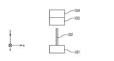
- FIG. 1A is a partial side view showing a reference example of a wireless power transmission system including a brush that functions as a radio wave shielding member.
- FIG. 1A shows a case where the distance between the power transmission unit 101 and the power reception unit 104 is large and wireless power transmission is not performed.
- FIG. 1B is a partial side view of the wireless power transmission system as viewed from another direction.
- the power transmission unit 101 is embedded and fixed in the ground of the energy station.
- a brush 102 made of a large number of linear members is attached to the power transmission unit 101.
- a power receiving unit 104 is provided on the bottom surface of the electric vehicle using the energy station.
- the power receiving surface of the power receiving unit 104 facing the power transmitting unit 101 is not necessarily flat, and may have a convex portion 103 such as a heat radiating fin.
- FIG. 2A is a partial side view showing a case where the power receiving unit 104 is arranged near the power transmitting unit 101 for charging.
- FIG. 2B is a partial side view of the wireless power transmission system viewed from another direction.
- the tip of the brush 102 is located at substantially the same height as the power receiving surface of the power receiving unit 104.
- a part of the brush 102 hits the convex portion 103.
- FIG. 2B shows the brush 102b in this part and the brush 102a in the other part not hitting the convex part 103.
- FIG. The brush 102b hits the convex portion 103 and bends.
- the inventors of the present invention focused on the possibility that a gap may occur in the bent portion 105 of the brush 102b as shown in FIG. 2B. If there is such a gap, the microwave may leak and the charging efficiency may decrease.
- an object of the present invention is to provide a wireless power transmission system that can more reliably prevent microwave leakage.
- a wireless power transmission system includes a power transmission antenna that outputs a microwave from an output surface, and a power receiving antenna that is disposed at a position facing the output surface during power transmission and receives the microwave output from the power transmission antenna at the input surface. And a shielding portion that electromagnetically shields the space between the power transmission antenna and the power reception antenna from the outside by a plurality of outer peripheral coil springs each having one end attached to a region surrounding the output surface of the power transmission antenna.
- the length of the plurality of outer peripheral coil springs is equal to or greater than the distance between the power transmitting antenna and the power receiving antenna during power transmission.
- the pitch of each of the plurality of outer peripheral coil springs is 1/50 or less of the wavelength of the microwave.
- the plurality of outer peripheral coil springs are inclined in the outward direction of the space from the power transmitting antenna side toward the power receiving antenna side.
- the wireless power transmission system further includes a plurality of inner peripheral coil springs that surround the output surface of the power transmission antenna and that have one end attached to a region on the inner peripheral side of the outer peripheral coil spring.
- the plurality of outer peripheral coil springs are inclined in the outward direction of the space from the power transmitting antenna side toward the power receiving antenna side.
- the plurality of inner peripheral coil springs are inclined inward in the space from the power transmitting antenna side toward the power receiving antenna side.
- a wireless power transmission system includes a power transmission antenna that outputs a microwave from an output surface, and a plurality of outer peripheral coil springs each having one end attached to a region surrounding the output surface of the power transmission antenna. And a shielding portion that is disposed at a position facing the output surface during power transmission and electromagnetically shields a space between the power receiving antenna that receives the microwave output from the power transmission antenna on the input surface from the outside.
- a wireless power transmission system is arranged at a position opposite to an output surface of a power transmission antenna that outputs a microwave from an output surface during power transmission, and receives the microwave output from the power transmission antenna at an input surface.
- a power receiving antenna and a shielding portion that electromagnetically shields a space between the power transmitting antenna and the power receiving antenna from the outside by a plurality of outer peripheral coil springs each having one end attached to a region surrounding the input surface of the power receiving antenna.
- the present invention provides a wireless power transmission system that can more reliably prevent microwave leakage.
- FIG. 1A is a partial side view of a wireless power transmission system in a reference example.
- FIG. 1B is a partial side view of the wireless power transmission system according to the reference example viewed from another direction.
- FIG. 2A is a partial side view of a wireless power transmission system in a reference example.
- FIG. 2B is a partial side view of the wireless power transmission system according to the reference example viewed from another direction.
- FIG. 3 is a top view of the power transmission unit.
- FIG. 4 is a bottom view of the power receiving unit.
- FIG. 5A is a partial side view of the wireless power transmission system.
- FIG. 1A is a partial side view of a wireless power transmission system in a reference example.
- FIG. 1B is a partial side view of the wireless power transmission system according to the reference example viewed from another direction.
- FIG. 3 is a top view of the power transmission unit.
- FIG. 4 is a bottom view of the power receiving unit.
- FIG. 5A is a partial side
- FIG. 5B shows the wireless power transmission system in the AA section of FIGS. 3 and 4.
- FIG. 6A is a partial side view of the wireless power transmission system.
- FIG. 6B shows the wireless power transmission system in the AA cross section of FIGS.
- FIG. 6C is an enlarged view of the contact portion 4 of FIG. 6B.
- FIG. 7 is a top view of the power transmission unit.
- FIG. 8A shows the wireless power transmission system in the AA section of FIG.
- FIG. 8B shows the wireless power transmission system in the AA section of FIG.
- FIG. 9 is a partial side view of the wireless power transmission system.
- FIG. 10 is a bottom view of the power receiving unit.
- FIG. 3 is a top view of the power transmission unit 1 of the wireless power transmission system according to the first embodiment viewed from the positive z-axis direction.
- the power transmission unit 1 has a rectangular planar shape in the example of FIG. 3, but may have other shapes such as a circle.
- a power transmission antenna 2 having a predetermined shape is disposed on the upper surface of the power transmission unit 1.
- the power transmission antenna 2 is an output surface that outputs a microwave.
- a coil spring 3 for shielding radio waves is attached to the upper surface of the power transmission unit 1 so as to surround the power transmission antenna 2.
- FIG. 4 is a bottom view of the power receiving unit 10 of the wireless power transmission system as viewed from the z-axis negative direction.
- the power receiving unit 10 has a rectangular planar shape in the example of FIG. 4, but may have other shapes.
- a power receiving antenna 11 having a predetermined shape is disposed on the lower surface of the power receiving unit 10.
- the power receiving antenna 11 is an input surface that is disposed at a position facing the power transmitting antenna 2 during power transmission and receives a microwave output by the power transmitting antenna 2.
- the power receiving antenna 11 is formed in a region including the power transmitting antenna 2 when viewed in the z-axis direction.
- the power receiving antenna 11 is formed so as to be larger than the power transmitting antenna 2, it is preferable that the microwave is received without being wasted even when the position of the power receiving unit 10 is slightly deviated from the power transmitting unit 1.
- the power receiving unit 10 converts the microwave input to the power receiving antenna 11 into electric power, and charges a storage battery or the like used as a power source for a drive motor of the electric vehicle.
- the power receiving antenna 11 has convex portions 12 such as fins for radiating heat generated in wireless power transmission.
- the power transmission unit 1 is disposed on the ground of the energy station with the power transmission antenna 2 facing upward.
- the power receiving unit 10 is attached to the bottom surface of the electric vehicle that is charged at the energy station with the power receiving antenna 11 facing downward.
- the electric vehicle stops at a predetermined position of the energy station and performs charging. In order to use wireless power transmission, operations such as connecting the plug of the energy station to an electric vehicle are not required.
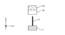
- FIG. 5A is a partial side view of the wireless power transmission system formed by the power transmission unit 1 illustrated in FIG. 3 and the power reception unit 10 illustrated in FIG. 4 as viewed from the x-axis direction.
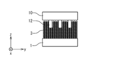
- FIG. 5B shows the wireless power transmission system in the AA section of FIGS. 3 and 4.
- 5A and 5B illustrate a case where the wireless power transmission system does not perform wireless power transmission and the distance between the power transmission unit 1 and the power reception unit 10 is long.
- the radio wave shielding member included in the power transmission unit 1 includes a large number of coil springs 3.
- the coil spring 3 is formed of a material that can obtain a radio wave shielding effect.
- the material is typically a metal, and phosphor bronze can be mentioned as a particularly suitable material.
- Each of the coil springs 3 is fixed in a region surrounding one end of the power transmission antenna of the power transmission unit 1 and arranged in a posture standing from the upper surface of the power transmission unit 1. In the present embodiment, the coil springs 3 have the same length.
- the upper ends of the multiple coil springs 3 are generally located in one plane. As shown in FIG. 5A, the adjacent coil springs 3 are arranged at positions close to each other, so that a large number of coil springs 3 form a sheet-like shielding surface. By this shielding surface, the space between the power transmitting antenna 2 and the power receiving antenna 11 is electromagnetically shielded from the outside.
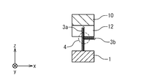
- FIG. 6A is a partial side view showing a case where the power receiving unit 10 is arranged near the power transmitting unit 1 in order to perform wireless power transmission.
- FIG. 6B shows the wireless power transmission system in the AA section of FIGS. 3 and 4 in this case.
- the length of the coil spring 3 is equal to or longer than the distance between the power transmission antenna 2 and the power reception antenna 11 during power transmission.
- the power receiving antenna 11 of the power receiving unit 10 is disposed at substantially the same height as the surface formed by the upper end of the coil spring 3 of the power transmitting unit 1. In this state, the coil spring 3a located in the region where the convex portion 12 of the power receiving unit 10 does not exist maintains a substantially straight posture and forms a sheet-like shielding surface.
- FIG. 6C shows an enlarged view of the contact portion 4.
- the coil spring 3 b In the contact portion 4, the coil spring 3 b is deformed into a shape along the shape of the convex portion 12 rather than a linear brush as shown in FIG. 1B.
- the coil spring 3 b that hits the surface of the convex portion 12 that is perpendicular to the length direction of the coil spring 3 b bends at a substantially right angle at the contact portion 4. Therefore, compared to the bent portion 105 in FIG. 2B, the gap formed on the sheet-shaped shielding surface can be suppressed small, and better radio wave shielding performance can be obtained.
- Coil springs have a property of bending in the direction along the convex shape at a shorter distance than a mere wire member when there is a convex portion at the abutting position.
- “bend” means that the wire of the coil spring is deformed within the range of elastic deformation, thereby showing the deformation of the coil spring as if it is also bent.
- the coil spring has such excellent shape followability.
- the length of the coil spring along the wire is longer than that of the wire member.
- the coil spring includes a wire longer than the wire member per unit length in the longitudinal direction. Therefore, when comparing a coil member and a wire member formed of the same wire, the coil spring may show a larger bend in the direction perpendicular to the longitudinal direction per unit length in the longitudinal direction than the wire member. it can. With such characteristics, the radio wave shielding member formed by the coil spring 3 can obtain excellent shape followability with respect to the unevenness of the power receiving unit 10 as shown in FIGS. 6B and 6C.
- the coil spring 3 Since the coil spring 3 has an excellent shape following ability, even when the electric vehicle stops a little from the specified position of the energy station, the leakage of microwaves due to the unevenness of the structure on the bottom surface is suppressed, which is high. Charge efficiency can be achieved.
- the adjacent coil springs 3 are arranged at a distance of 1/10 or less, preferably 1/50 or less of the wavelength of the microwave (typically 2.45 GHz).
- the pitch of the coil spring 3, that is, the pitch of the wire at the same deflection angle in the cylindrical coordinates around the central axis of the coil spring 3 is also 1/10 or less, preferably 1/50 or less of the wavelength of the microwave. desirable.
- the coil spring used by the inventor is a minute one with a wire rod diameter of 0.3 mm and a total coil spring diameter of 0.8 mm, and has a shape followability superior to that of a brush made of a linear or rod-like wire member. I was able to get it.
- FIG. 7 shows a power transmission unit 1a of the wireless power transmission system in the second embodiment.
- the power reception unit 10 has the same configuration as that of the first embodiment.
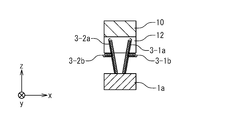
- the power transmission unit 1a in the present embodiment surrounds the inner peripheral coil spring 3-2 formed in a region surrounding the region where the power transmission antenna 2 is formed, and the inner peripheral coil spring 3-2 via a gap having a predetermined width. And an outer peripheral coil spring 3-1 formed in the region.
- FIG. 8A shows a wireless power transmission system including the power transmission unit 1a and the power reception unit 10 in the AA cross section of FIG.
- the outer peripheral coil spring 3-1 is directed to the power transmitting section 1a so that the central axis is inclined outwardly from the power transmitting antenna 2 toward the power receiving antenna 11 (that is, from the root of each coil spring 3-1 toward the tip). Installed.
- An angle ⁇ 1 of the central axis with respect to a line perpendicular to the upper surface of the power transmission antenna 2 is about 10 degrees, and is preferably 5 degrees or more and 15 degrees or less.
- the inner peripheral coil spring 3-2 is grounded to the power transmitting unit 1a so that the central axis thereof is inclined inward from the power transmitting antenna 2 toward the power receiving antenna 11.
- An angle ⁇ 2 of the central axis with respect to a line perpendicular to the upper surface of the power transmission antenna 2 is about 10 degrees, and preferably 5 degrees or more and 15 degrees or less.
- FIG. 8A is a partial side view of the wireless power transmission system showing a case where the power receiving unit 10 is arranged near the power transmitting unit 1a in order to perform wireless power transmission.
- FIG. 8B shows the wireless power transmission system in the AA section of FIG. 7 in this case.
- the power receiving antenna 11 of the power receiving unit 10 is disposed at substantially the same height as the surface formed by the upper end of the coil spring 3 of the power transmitting unit 1a.
- the outer peripheral coil spring 3-1a and the inner peripheral coil spring 3-2a which are located in a region where the convex portion 12 of the power receiving unit 10 does not exist, maintain a substantially straight posture, and each forms a sheet-like shielding surface. .
- the inner peripheral coil spring 3-1b located in the region where the convex portion 12 exists bends mainly to the outer peripheral side of the power transmission unit 1a, that is, the side opposite to the power transmission antenna 2 due to the angle ⁇ 1.
- the outer peripheral coil spring 3-1b can be bent to the outer peripheral side uniformly with a small force because of the angle ⁇ 1.
- the inner peripheral coil spring 3-2b located in the region where the convex portion 12 exists is bent mainly toward the inner peripheral side of the power transmission unit 1a, that is, the power transmission antenna 2 side due to the angle ⁇ 2. Because of the angle ⁇ 2, the inner peripheral coil spring 3-2b can be bent to the inner peripheral side uniformly with a small force. Since the outer peripheral coil spring 3-1b and the inner peripheral coil spring 3-2b bend on the opposite sides, the deformation of each other is not hindered.
- the outer peripheral coil spring 3-1 and the inner peripheral coil spring 3-2 form a shielding surface having a high shielding effect. Since the portion of the microwave generated by the power transmission unit 1a that has leaked the shielding surface formed by the inner coil spring 3-2 is shielded by the outer coil spring 3-1, wireless power transmission with less microwave leakage is realized. Is done. In order to obtain such a double shielding effect, it is desirable that the outer peripheral coil spring 3-1 and the inner peripheral coil spring 3-2 are not adjacent to each other and are formed through a gap having a predetermined width. Of course, the number of coil springs may be three or more.
- a good radio wave shielding effect can be obtained even when a coil spring arranged to be inclined toward the outer periphery side like the outer peripheral coil spring 3-1 of the present embodiment is applied to the coil spring 3 of one example in the first embodiment.
- FIG. 9 is a partial side view of the wireless power transmission system according to the third embodiment viewed from the x-axis direction.
- a coil spring 13 for shielding radio waves is provided on the power receiving unit 10b side.
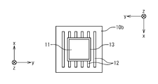
- FIG. 10 is a bottom view of the power receiving unit 10b.
- the power receiving unit 10 b includes a power receiving antenna 11.
- a large number of coil springs 13 are arranged so as to surround the power receiving antenna 11.
- One end of each coil spring 13 is fixed to a region surrounding the power receiving antenna 11 of the power receiving unit 10b, and is arranged in a posture standing from the lower surface of the power receiving unit 10b.
- the coil spring 13 in the region where the convex portion 14 exists is bent in a shape along the convex portion 14.
- a suitable performance can also be obtained by arranging the coil spring 13 in the present embodiment like the outer peripheral coil spring 3-1 shown in FIGS. 8A and 8B.
- each of the coil springs 13 is disposed obliquely in a direction away from the power receiving antenna 11 from the outer peripheral side, that is, from the root toward the tip.
- it is also effective to install a plurality of rows of coil springs as in the second embodiment in the power receiving unit 10b.
- the power transmission unit is fixed to the ground with the power transmission antenna facing upward, and the power reception unit is disposed downward.
- the effect of the present invention can be obtained regardless of which direction.
- the case where the power transmission unit or the power reception unit has a convex portion has been described.
- the vicinity of the power transmission unit or the power reception unit has an arbitrary uneven structure, or the relative distance between the power transmission unit and the power reception unit. Even when there is a variation in the frequency, good electromagnetic wave shielding performance can be obtained by using a coil spring in the same manner.
Landscapes
- Engineering & Computer Science (AREA)
- Power Engineering (AREA)
- Computer Networks & Wireless Communication (AREA)
- Transportation (AREA)
- Mechanical Engineering (AREA)
- Life Sciences & Earth Sciences (AREA)
- Sustainable Development (AREA)
- Sustainable Energy (AREA)
- Physics & Mathematics (AREA)
- Electromagnetism (AREA)
- Electric Propulsion And Braking For Vehicles (AREA)
Abstract
Description
[第1実施形態]
図3は、第1実施形態における無線送電システムの送電部1をz軸正方向から見た上面図である。送電部1は、図3の例では四角形の平面形状を有しているが、円形などその他の形状であってもよい。送電部1の上面には所定の形状を有する送電アンテナ2が配置される。送電アンテナ2は、マイクロ波を出力する出力面である。送電部1の上面には、送電アンテナ2を取り囲むように電波を遮蔽するためのコイルばね3が取り付けられる。
図7は、第2実施形態における無線送電システムの送電部1aを示す。本実施形態の無線送電システムにおいて、受電部10は第1実施形態と同じ構成を有する。本実施形態における送電部1aは、送電アンテナ2が形成された領域を取り囲む領域に形成された内周コイルばね3-2と、その内周コイルばね3-2を所定幅のギャップを介して取り囲む領域に形成された外周コイルばね3-1とを有する。
図9は、第3実施形態における無線送電システムをx軸方向から見た部分側面図である。本実施形態においては、電波を遮蔽するためのコイルばね13が受電部10bの側に設けられている。図10は受電部10bの下面図である。受電部10bは受電アンテナ11を有する。受電アンテナ11を取り囲むように多数のコイルばね13が配置される。各々のコイルばね13は、その一端が受電部10bの受電アンテナ11を取り囲む領域に固定され、受電部10bの下面から立てられた姿勢で配置される。
Claims (9)
- 出力面からマイクロ波を出力する送電アンテナと、
送電時に前記出力面に対向する位置に配置され、前記送電アンテナが出力するマイクロ波を入力面において受信する受電アンテナと、
前記送電アンテナの前記出力面を取り囲む領域にそれぞれの一端が取り付けられた複数の外周コイルばねによって前記送電アンテナと前記受電アンテナとの間の空間を外部から電磁的に遮蔽する遮蔽部
とを具備する無線送電システム。 - 請求項1に記載された無線送電システムであって、
前記複数の外周コイルばねの長さは、送電時における前記送電アンテナと前記受電アンテナとの距離以上である
無線送電システム。 - 請求項1又は2に記載された無線送電システムであって、
前記複数の外周コイルばねの各々のピッチは前記マイクロ波の波長の50分の1以下である
無線送電システム。 - 請求項1から3のいずれかに記載された無線送電システムであって、
前記複数の外周コイルばねは、前記送電アンテナの側から前記受電アンテナの側に向って、前記空間の外側方向に傾斜する
無線送電システム。 - 請求項1から3のいずれかに記載された無線送電システムであって、
更に、前記送電アンテナの前記出力面を取り囲み且つ前記外周コイルばねよりも内周側の領域にそれぞれの一端が取り付けられた複数の内周コイルばねを具備する
無線送電システム。 - 請求項4に記載された無線送電システムであって、
前記複数の外周コイルばねは、前記送電アンテナの側から前記受電アンテナの側に向って、前記空間の外側方向に傾斜する
無線送電システム。 - 請求項5又は6に記載された無線送電システムであって、
前記複数の内周コイルばねは、前記送電アンテナの側から前記受電アンテナの側に向って、前記空間の内側方向に傾斜する
無線送電システム。 - 出力面からマイクロ波を出力する送電アンテナと、
前記送電アンテナの前記出力面を取り囲む領域にそれぞれの一端が取り付けられた複数の外周コイルばねによって、前記送電アンテナと、送電時に前記出力面に対向する位置に配置され、前記送電アンテナが出力するマイクロ波を入力面において受信する受電アンテナとの間の空間を外部から電磁的に遮蔽する遮蔽部
とを具備する無線送電システム。 - 送電時に、出力面からマイクロ波を出力する送電アンテナの前記出力面に対向する位置に配置され、前記送電アンテナが出力するマイクロ波を入力面において受信する受電アンテナと、
前記受電アンテナの前記入力面を取り囲む領域にそれぞれの一端が取り付けられた複数の外周コイルばねによって前記送電アンテナと前記受電アンテナとの間の空間を外部から電磁的に遮蔽する遮蔽部
とを具備する無線送電システム。
Priority Applications (2)
| Application Number | Priority Date | Filing Date | Title |
|---|---|---|---|
| US13/379,772 US9124141B2 (en) | 2009-06-26 | 2010-06-25 | Wireless power transmission system |
| CN201080028368.9A CN102460902B (zh) | 2009-06-26 | 2010-06-25 | 无线送电系统 |
Applications Claiming Priority (2)
| Application Number | Priority Date | Filing Date | Title |
|---|---|---|---|
| JP2009151898A JP5320184B2 (ja) | 2009-06-26 | 2009-06-26 | 無線送電システム |
| JP2009-151898 | 2009-06-26 |
Publications (1)
| Publication Number | Publication Date |
|---|---|
| WO2010150872A1 true WO2010150872A1 (ja) | 2010-12-29 |
Family
ID=43386641
Family Applications (1)
| Application Number | Title | Priority Date | Filing Date |
|---|---|---|---|
| PCT/JP2010/060835 Ceased WO2010150872A1 (ja) | 2009-06-26 | 2010-06-25 | 無線送電システム |
Country Status (4)
| Country | Link |
|---|---|
| US (1) | US9124141B2 (ja) |
| JP (1) | JP5320184B2 (ja) |
| CN (1) | CN102460902B (ja) |
| WO (1) | WO2010150872A1 (ja) |
Families Citing this family (12)
| Publication number | Priority date | Publication date | Assignee | Title |
|---|---|---|---|---|
| KR101294465B1 (ko) * | 2011-10-11 | 2013-08-07 | 엘지이노텍 주식회사 | 무선전력 중계 장치, 무선전력 중계기, 무선전력 전송 시스템 및 무선전력 전송 방법 |
| US10050463B2 (en) * | 2013-08-15 | 2018-08-14 | Humavox Ltd. | Wireless charging device |
| JP5975359B2 (ja) | 2014-04-23 | 2016-08-23 | パナソニックIpマネジメント株式会社 | ワイヤレス給電方法及びワイヤレス給電システム |
| JP6025071B2 (ja) * | 2014-04-23 | 2016-11-16 | パナソニックIpマネジメント株式会社 | ワイヤレス給電装置 |
| US9722450B2 (en) * | 2014-07-02 | 2017-08-01 | Apple Inc. | Inductive power transmission geometry |
| KR101673767B1 (ko) * | 2015-05-11 | 2016-11-08 | 현대자동차주식회사 | 무선 충전용 기기 |
| US10651670B1 (en) | 2016-02-19 | 2020-05-12 | Apple Inc. | Electronic devices with wireless charging antenna arrays |
| DE112017002491T5 (de) * | 2016-05-16 | 2019-02-28 | Mitsubishi Heavy Industries, Ltd. | Drahtlose energieversorgungsvorrichtung, telemetrisches messsystem, rotationsmaschine, system zur drahtlosen energieversorgung eines rotierenden körpers, und turbinensystem |
| RU2643177C1 (ru) | 2016-12-14 | 2018-01-31 | Самсунг Электроникс Ко., Лтд. | Микроволновое беспроводное зарядное устройство с фокусировкой микроволнового поля |
| KR102126773B1 (ko) * | 2018-05-15 | 2020-06-25 | 주식회사 위츠 | 무선 충전용 방열 부재 및 이를 구비하는 전자 기기 |
| JP7200709B2 (ja) * | 2019-01-31 | 2023-01-10 | 株式会社オートネットワーク技術研究所 | 給電装置 |
| TWI804939B (zh) * | 2021-07-30 | 2023-06-11 | 帥群微電子股份有限公司 | 無線充電系統及其充電站 |
Citations (4)
| Publication number | Priority date | Publication date | Assignee | Title |
|---|---|---|---|---|
| JP2008054424A (ja) * | 2006-08-24 | 2008-03-06 | Mitsubishi Heavy Ind Ltd | 受電装置及び送電装置並びに車両 |
| JP2009303316A (ja) * | 2008-06-11 | 2009-12-24 | Mitsubishi Heavy Ind Ltd | 車両用受電装置 |
| US20100065352A1 (en) * | 2008-09-18 | 2010-03-18 | Toyota Jidosha Kabushiki Kaisha | Noncontact electric power receiving device, noncontact electric power transmitting device, noncontact electric power feeding system, and electrically powered vehicle |
| JP2010098807A (ja) * | 2008-10-15 | 2010-04-30 | Toyota Motor Corp | 非接触給電システム |
Family Cites Families (6)
| Publication number | Priority date | Publication date | Assignee | Title |
|---|---|---|---|---|
| US5117066A (en) | 1988-04-25 | 1992-05-26 | Peter J. Balsells | Retaining and locking electromagnetic gasket |
| US5474309A (en) * | 1993-06-11 | 1995-12-12 | Bal Seal Engineering Company, Inc. | Gasket assembly for sealing electromagnetic waves |
| US5545842A (en) * | 1993-10-26 | 1996-08-13 | Bal Seal Engineering Company, Inc. | Radially mounted spring to connect, lock and unlock, and for snap-on fastening, and for mechanical, electromagnetic shielding, electrical conductivity, and thermal dissipation with environmental sealing |
| DE69714879T2 (de) * | 1996-01-30 | 2003-05-08 | Sumitomo Wiring Systems, Ltd. | Verbindungssystem mit zugehörigem Verfahren |
| US6967462B1 (en) * | 2003-06-05 | 2005-11-22 | Nasa Glenn Research Center | Charging of devices by microwave power beaming |
| JP4898348B2 (ja) * | 2006-08-24 | 2012-03-14 | 三菱重工業株式会社 | 電力供給装置及び電力供給システム |
-
2009
- 2009-06-26 JP JP2009151898A patent/JP5320184B2/ja not_active Expired - Fee Related
-
2010
- 2010-06-25 CN CN201080028368.9A patent/CN102460902B/zh not_active Expired - Fee Related
- 2010-06-25 WO PCT/JP2010/060835 patent/WO2010150872A1/ja not_active Ceased
- 2010-06-25 US US13/379,772 patent/US9124141B2/en not_active Expired - Fee Related
Patent Citations (4)
| Publication number | Priority date | Publication date | Assignee | Title |
|---|---|---|---|---|
| JP2008054424A (ja) * | 2006-08-24 | 2008-03-06 | Mitsubishi Heavy Ind Ltd | 受電装置及び送電装置並びに車両 |
| JP2009303316A (ja) * | 2008-06-11 | 2009-12-24 | Mitsubishi Heavy Ind Ltd | 車両用受電装置 |
| US20100065352A1 (en) * | 2008-09-18 | 2010-03-18 | Toyota Jidosha Kabushiki Kaisha | Noncontact electric power receiving device, noncontact electric power transmitting device, noncontact electric power feeding system, and electrically powered vehicle |
| JP2010098807A (ja) * | 2008-10-15 | 2010-04-30 | Toyota Motor Corp | 非接触給電システム |
Non-Patent Citations (1)
| Title |
|---|
| "Hi Sesshoku Kyuden Sochi", JAPAN INSTITUTE OF INVENTION AND INNOVATION, JOURNAL OF TECHNICAL DISCLOSURE, 9 November 2009 (2009-11-09), pages 506456 * |
Also Published As
| Publication number | Publication date |
|---|---|
| US9124141B2 (en) | 2015-09-01 |
| US20120126631A1 (en) | 2012-05-24 |
| JP5320184B2 (ja) | 2013-10-23 |
| CN102460902B (zh) | 2014-07-30 |
| CN102460902A (zh) | 2012-05-16 |
| JP2011010472A (ja) | 2011-01-13 |
Similar Documents
| Publication | Publication Date | Title |
|---|---|---|
| JP5320184B2 (ja) | 無線送電システム | |
| TWI441388B (zh) | Multi - frequency antenna | |
| US10847310B2 (en) | Coil unit, and power transmitting device, power receiving device and wireless power transmission system using the coil unit | |
| JP5603636B2 (ja) | レドーム、アンテナ装置、およびレーダ装置 | |
| US9466957B2 (en) | Wire harness | |
| JP4913093B2 (ja) | 光通信モジュールおよび光学結合部被覆部材 | |
| JP7140031B2 (ja) | ワイヤハーネス | |
| CN102185174A (zh) | 一种无线终端及无线终端双天线系统的设计方法 | |
| US20140361629A1 (en) | Antenna for harvesting rf energy | |
| CN106469695B (zh) | 电子电气设备 | |
| US20200381139A1 (en) | Wire harness | |
| KR102607869B1 (ko) | 고전압 커넥터 차폐 구조 | |
| JP5904786B2 (ja) | コイルユニット及び、非接触給電装置 | |
| JP5470156B2 (ja) | アンテナ装置 | |
| KR20090096217A (ko) | 시스템 손실을 보상한 누설 동축 케이블 | |
| JP7758058B2 (ja) | アンテナ装置、無線電力伝送装置、及び無線電力伝送システム | |
| CN109716596B (zh) | 同轴连接器 | |
| JP2019170104A (ja) | ケーブル接続部の放熱構造 | |
| CN111193326B (zh) | 平行二线单元 | |
| JP5473157B2 (ja) | 無線通信装置 | |
| JP2011030323A (ja) | シールド部材及びワイヤハーネス | |
| CN209981513U (zh) | 连接器 | |
| JP5026568B2 (ja) | アンテナ | |
| JP2006318680A (ja) | シールド導電体 | |
| JP2018067860A (ja) | アンテナ |
Legal Events
| Date | Code | Title | Description |
|---|---|---|---|
| WWE | Wipo information: entry into national phase |
Ref document number: 201080028368.9 Country of ref document: CN |
|
| 121 | Ep: the epo has been informed by wipo that ep was designated in this application |
Ref document number: 10792190 Country of ref document: EP Kind code of ref document: A1 |
|
| NENP | Non-entry into the national phase |
Ref country code: DE |
|
| WWE | Wipo information: entry into national phase |
Ref document number: 13379772 Country of ref document: US |
|
| 122 | Ep: pct application non-entry in european phase |
Ref document number: 10792190 Country of ref document: EP Kind code of ref document: A1 |