WO2010150581A1 - 導光ユニットおよび情報記録装置 - Google Patents
導光ユニットおよび情報記録装置 Download PDFInfo
- Publication number
- WO2010150581A1 WO2010150581A1 PCT/JP2010/054201 JP2010054201W WO2010150581A1 WO 2010150581 A1 WO2010150581 A1 WO 2010150581A1 JP 2010054201 W JP2010054201 W JP 2010054201W WO 2010150581 A1 WO2010150581 A1 WO 2010150581A1
- Authority
- WO
- WIPO (PCT)
- Prior art keywords
- light
- unit
- diffraction grating
- diffracted
- light source
- Prior art date
- Legal status (The legal status is an assumption and is not a legal conclusion. Google has not performed a legal analysis and makes no representation as to the accuracy of the status listed.)
- Ceased
Links
Images








Classifications
-
- G—PHYSICS
- G11—INFORMATION STORAGE
- G11B—INFORMATION STORAGE BASED ON RELATIVE MOVEMENT BETWEEN RECORD CARRIER AND TRANSDUCER
- G11B5/00—Recording by magnetisation or demagnetisation of a record carrier; Reproducing by magnetic means; Record carriers therefor
- G11B5/127—Structure or manufacture of heads, e.g. inductive
- G11B5/31—Structure or manufacture of heads, e.g. inductive using thin films
- G11B5/3109—Details
- G11B5/313—Disposition of layers
- G11B5/3133—Disposition of layers including layers not usually being a part of the electromagnetic transducer structure and providing additional features, e.g. for improving heat radiation, reduction of power dissipation, adaptations for measurement or indication of gap depth or other properties of the structure
- G11B5/314—Disposition of layers including layers not usually being a part of the electromagnetic transducer structure and providing additional features, e.g. for improving heat radiation, reduction of power dissipation, adaptations for measurement or indication of gap depth or other properties of the structure where the layers are extra layers normally not provided in the transducing structure, e.g. optical layers
-
- G—PHYSICS
- G11—INFORMATION STORAGE
- G11B—INFORMATION STORAGE BASED ON RELATIVE MOVEMENT BETWEEN RECORD CARRIER AND TRANSDUCER
- G11B5/00—Recording by magnetisation or demagnetisation of a record carrier; Reproducing by magnetic means; Record carriers therefor
- G11B5/48—Disposition or mounting of heads or head supports relative to record carriers ; arrangements of heads, e.g. for scanning the record carrier to increase the relative speed
- G11B5/58—Disposition or mounting of heads or head supports relative to record carriers ; arrangements of heads, e.g. for scanning the record carrier to increase the relative speed with provision for moving the head for the purpose of maintaining alignment of the head relative to the record carrier during transducing operation, e.g. to compensate for surface irregularities of the latter or for track following
- G11B5/60—Fluid-dynamic spacing of heads from record-carriers
- G11B5/6005—Specially adapted for spacing from a rotating disc using a fluid cushion
-
- G—PHYSICS
- G11—INFORMATION STORAGE
- G11B—INFORMATION STORAGE BASED ON RELATIVE MOVEMENT BETWEEN RECORD CARRIER AND TRANSDUCER
- G11B7/00—Recording or reproducing by optical means, e.g. recording using a thermal beam of optical radiation by modifying optical properties or the physical structure, reproducing using an optical beam at lower power by sensing optical properties; Record carriers therefor
- G11B7/12—Heads, e.g. forming of the optical beam spot or modulation of the optical beam
- G11B7/135—Means for guiding the beam from the source to the record carrier or from the record carrier to the detector
- G11B7/1353—Diffractive elements, e.g. holograms or gratings
-
- G—PHYSICS
- G11—INFORMATION STORAGE
- G11B—INFORMATION STORAGE BASED ON RELATIVE MOVEMENT BETWEEN RECORD CARRIER AND TRANSDUCER
- G11B7/00—Recording or reproducing by optical means, e.g. recording using a thermal beam of optical radiation by modifying optical properties or the physical structure, reproducing using an optical beam at lower power by sensing optical properties; Record carriers therefor
- G11B7/12—Heads, e.g. forming of the optical beam spot or modulation of the optical beam
- G11B7/135—Means for guiding the beam from the source to the record carrier or from the record carrier to the detector
- G11B7/1384—Fibre optics
-
- G—PHYSICS
- G11—INFORMATION STORAGE
- G11B—INFORMATION STORAGE BASED ON RELATIVE MOVEMENT BETWEEN RECORD CARRIER AND TRANSDUCER
- G11B5/00—Recording by magnetisation or demagnetisation of a record carrier; Reproducing by magnetic means; Record carriers therefor
- G11B2005/0002—Special dispositions or recording techniques
- G11B2005/0005—Arrangements, methods or circuits
-
- G—PHYSICS
- G11—INFORMATION STORAGE
- G11B—INFORMATION STORAGE BASED ON RELATIVE MOVEMENT BETWEEN RECORD CARRIER AND TRANSDUCER
- G11B5/00—Recording by magnetisation or demagnetisation of a record carrier; Reproducing by magnetic means; Record carriers therefor
- G11B2005/0002—Special dispositions or recording techniques
- G11B2005/0005—Arrangements, methods or circuits
- G11B2005/0021—Thermally assisted recording using an auxiliary energy source for heating the recording layer locally to assist the magnetization reversal
Definitions
- the present invention relates to a light guide unit that guides light emitted from a light source to an optical waveguide, and an information recording apparatus using the light guide unit.
- Patent Document 1 a heat-assisted magnetic information recording technique using light radiation has been known (for example, Patent Document 1).
- heat assist light is irradiated from the lower end of a planar waveguide with a condensing function.
- a high coercive force medium is used as the recording medium in order to improve the recording density.
- This high coercive force medium is a recording medium that can achieve both high-density recording and thermal stability, and can stably store magnetic information (recording bits) recorded at high density for a long period of time.
- thermal energy is locally applied to the recording surface prior to rewriting of magnetic information.
- thermal energy is locally applied to the recording surface, and the coercivity of the magnetic information to be rewritten is reduced. Therefore, even when a high coercive force medium is used as the recording medium, the magnetic information to be rewritten is easily reversed in magnetization, and the rewriting of the magnetic information is easily performed.
- the temperature of the recording surface irradiated with light rapidly decreases thereafter, and the coercive force of the recording surface returns to the original high coercive force state. For this reason, the rewritten magnetic information is stably stored.
- Patent Document 1 only describes that when light is incident on the diffraction grating of the planar waveguide with a condensing function from the light source, the light is inclined and incident on the diffraction grating. There is no description of a specific method of how the light from the light is incident.
- an object of the present invention is to provide a light guide unit capable of improving the utilization efficiency of light emitted from a light source, and an information recording apparatus using the same.
- the invention of claim 1 is a light guide unit that guides light emitted from a light source, and has a grating coupler and transmits light incident through the grating coupler. And a reflection type diffraction grating, provided on the opposite side to the light source across the optical waveguide, and comprising a light deflecting unit for deflecting light emitted from the light source by the diffraction grating,
- the light deflection unit is a diffraction in which 0th-order light out of the diffracted light diffracted by the diffraction grating travels farther from the optical waveguide as viewed from the light deflection unit and is diffracted by the diffraction grating. It is set so that at least primary light out of the light is incident on the grating coupler.
- the light emitted from the light source and the zero-order light diffracted by the diffraction grating are formed according to the equation (1).
- An angle ⁇ 1 is obtained.
- the first position is defined as the position where the light emitted from the light source reaches the diffraction grating and the second position is defined as the lower end position of the optical waveguide
- a 1 The absolute value of the vertical component of the vector connecting the first and second positions is indicated
- d 1 is the absolute value of the horizontal component of the vector connecting the first and second positions.
- an information recording apparatus for recording magnetic information on a recording medium, extending in one direction and capable of swinging about a swing shaft provided near one end in the extending direction.
- An arm portion a light source that emits light from one end side to the other end side of the arm portion in the extending direction, and a light source that is attached near the other end of the arm portion, and that emits light emitted from the light source.
- An optical deflection unit that deflects light emitted from the light source by a diffraction grating, and the magnetic recording unit, the optical waveguide, and the optical deflection unit are
- the optical waveguide has a grating coupler and transmits light incident through the grating coupler, and the optical deflection unit Of the diffracted light diffracted by the grating, zero-order light reaches the recording medium farther from the optical waveguide as viewed from the light deflection unit, and at least one of the diffracted lights diffracted by the diffraction grating. It is set such that the next light is incident on the grating coupler.
- the head portion and the light deflection portion are attached to the arm portion so as to face the same recording surface of the recording medium. It is characterized by being.
- the head portion is attached to the arm portion so as to face the recording medium, and the light deflection portion is the arm portion.
- the zero-order light and the at least first-order light diffracted by the diffraction grating are disposed on the opposite side of the head portion with respect to the optical waveguide side through a through hole provided in the arm portion. It is characterized by making it reach
- the light emitted from the light source is diffracted by the diffraction grating according to the equation (1).
- An angle ⁇ 1 formed by zero-order light is obtained.
- the first position is a position where the light emitted from the light source reaches the diffraction grating
- the second position is, the lower end position of the optical waveguide, as defined respectively, a 1
- the first The absolute value of the vertical component of the vector connecting the first and second positions is indicated
- d 1 is the absolute value of the horizontal component of the vector connecting the first and second positions.
- the light emitted from the light source is folded back to the optical waveguide side by the diffraction grating of the light deflection unit.
- the diffracted light diffracted by the diffraction grating at least the first-order light is incident on the grating coupler of the optical waveguide, and the zero-order light travels farther than the optical waveguide. Therefore, the 0th-order light diffracted by the diffraction grating can be used as illumination light that illuminates far away from the optical waveguide, and the 0th-order light can be used effectively.
- the light emitted from the swing axis (one end) side of the arm portion to the other end side is guided by the diffraction grating of the light deflection portion. Folded to the waveguide side.
- the diffracted light diffracted by the diffraction grating at least the first-order light is incident on the grating coupler of the optical waveguide, and the zero-order light reaches a recording medium far from the optical waveguide. Therefore, the 0th order light diffracted by the diffraction grating can be used as illumination light for illuminating the recording medium, and the 0th order light can be effectively utilized.
- the incident angle of the diffracted light incident on the grating coupler is maintained at an appropriate incident angle. . That is, the influence of the wavelength change is absorbed by the diffraction grating of the light deflection unit. Therefore, even when the wavelength of light emitted from the light source is changed, diffracted light can be favorably incident on the optical waveguide.
- the 0th-order light diffracted by the diffraction grating reaches the recording medium farther from the optical waveguide as viewed from the light deflection unit. Further, the diffraction angle of the 0th-order light in the diffraction grating does not change even if the wavelength of the light emitted from the light source changes. Thereby, the arrival position of the zero-order light reaching the recording medium is not affected by the wavelength change. Therefore, by adjusting the arrival position of the 0th-order light on the recording medium so as to be a predetermined position, the attachment adjustment of the light deflection unit can be performed accurately and easily.
- the head portion and the optical deflection portion are attached to the arm portion so as to face the recording surface of the recording medium. That is, it is not necessary to arrange the light deflection unit in the space opposite to the recording medium with the arm portion interposed therebetween. Therefore, space saving near the arm portion can be realized.
- the light deflection unit it is not necessary to arrange the light deflection unit in a narrow space between the head unit and the recording medium. Therefore, it is possible to increase the degree of freedom of attachment of the light deflection unit, and it is possible to easily adjust the attachment position of the light deflection unit.
- FIG. 5 is a side sectional view taken along line VV in FIG. 2. It is a side view which shows an example of a structure of the light guide unit in 1st Embodiment. It is a side view which shows an example of a structure of a slider part. It is a front view which shows an example of a structure of a light assist part. It is a figure for demonstrating the detailed structure of an optical waveguide.
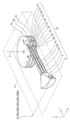
- FIG. 1 is a perspective view schematically showing an example of the configuration of the information recording apparatus 1 in the present embodiment.
- the information recording apparatus 1 is a heat-assisted magnetic information recording apparatus, and can be used as a so-called hard disk drive. Further, a high coercive force medium is used as the recording medium of the information recording apparatus 1.
- the information recording apparatus 1 when the magnetic information recorded on the high coercive force medium is rewritten, the information recording apparatus 1 locally irradiates the recording surface of the high coercive force medium and locally applies thermal energy. As a result, the temperature of the region (rewrite region) to which the thermal energy is applied rises, and the coercivity of the magnetic information in the rewrite region decreases. Therefore, even when a high coercive force medium is used as a recording medium, rewriting of magnetic information can be easily performed.
- the temperature of the rewriting area to which the thermal energy based on the light radiation is applied falls rapidly thereafter. Therefore, the coercive force of the recording surface returns to the original high coercive force state. Therefore, the rewritten magnetic information is stably stored on the recording surface of the high coercive force medium.
- the information recording apparatus 1 mainly includes a housing 1a, first to third recording disks 2a to 2c, a head signal control unit 9, and an arm mechanism 10.
- . 1 and the subsequent drawings have an XYZ orthogonal coordinate system in which the Z-axis direction is a vertical direction and the XY plane is a horizontal plane, as necessary, in order to clarify the directional relationship. .
- the housing 1a is a substantially rectangular parallelepiped box. In the inner space of the housing 1a, the first to third recording disks 2a to 2c and the arm mechanism 10 are hermetically stored.
- the first to third recording disks 2a to 2c are substantially disc-shaped recording media, and are constituted by a high coercive force medium. As shown in FIG. 1, the first to third recording disks 2a to 2c are provided in this order from the upper side to the lower side (Z-axis minus direction). Further, as shown in FIG. 1, adjacent recording disks 2a to 2c are separated from each other by a predetermined minute distance (for example, 1 mm or less), and the first to fifth recording surfaces 3a to 3e are provided. It arrange
- the head signal control unit 9 is a control circuit attached to the side surface of the actuator 6 as shown in FIG.
- the head signal control unit 9 causes the first to fifth slider units 31 to 35 to execute magnetic recording and magnetic reproduction processes.
- the head signal control unit 9 executes a process of amplifying the reproduction signal read by each slider unit 31 to 35. Further, the head signal control unit 9 causes the magnetic recording process to be performed on one of the first to fifth slider units 31 to 35 which is a recording target.
- the arm mechanism 10 moves the first to fifth light deflecting portions 21 to 25 and the first to fifth slider portions 31 to 35 in the tracking direction mA with respect to the first to third recording disks 2a to 2c. It is a moving mechanism to move.
- the first to fifth slider portions 31 to 35 are moved relative to the corresponding first to fifth recording surfaces 3a to 3e. Therefore, the magnetic information at the desired position of the rotating first to third recording disks 2a to 2c is read, or the magnetic information at the desired position of the first to third recording disks 2a to 2c is rewritten.
- the detailed configuration of the arm mechanism 10 will be described later. Further, the number of recording disks and the number of recording surfaces (the number of corresponding slider portions) can be changed, and are not limited to the numbers in the present embodiment.
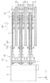
- FIG. 2 is a plan view showing an example of the configuration of the arm mechanism 10 in the present embodiment.
- 3 is a side sectional view taken along line VV in FIG.
- the arm mechanism 10 mainly includes a swing shaft 5, an actuator 6, and a plurality of (three in the present embodiment) arm portions 41 to 43. .
- the first to third arm portions 41 to 43 are cantilever members having the same shape. As shown in FIG. 3, the arm portions 41 to 43 are fixed to the swing shaft 5 and extend from the swing shaft 5 side to the first to third recording disks 2a to 2c.
- the first to third arm portions 41 to 43 are provided in this order from the upper side to the lower side.
- the first recording disk 2a is sandwiched between the first and second arm portions 42, and the second recording disk 2b is sandwiched between the second and third arm portions 43, respectively.
- a third recording disk 2 c is disposed below the third arm portion 43.
- first to third arm portions 41 to 43 are linked to the actuator 6 via the swing shaft 5. Therefore, when the actuator 6 is driven, the arm portions 41 to 43 swing around the swing shaft 5 substantially parallel to the Z axis.
- the first arm portion 41 extends in one direction and can swing around a swing shaft 5 provided near one end 45 in the extending direction AR1. As shown in FIG. 3, the first arm portion 41 mainly includes an arm main body portion 41a and a suspension portion 41b.
- the arm main body 41 a is provided on one end 45 side (fixed end side) of the first arm 41 and is fixed to the swing shaft 5.
- the arm main body 41a is made of a material having a larger size (thickness) in the height direction and higher rigidity than the suspension 41b.
- the suspension part 41b is formed of a flexible material. As shown in FIG. 3, the suspension portion 41b is provided on the other end 46 side (free end side) of the first arm portion 41, and is fixed to the lower side of the arm main body portion 41a.
- the first light source LS1 supplies light irradiated to the first recording surface 3a (the upper surface of the first recording disk 2a) for heat assist. As shown in FIG. 3, the first light source LS1 is attached to the lower surface side of the arm main body 41a. The light Li emitted from the first light source LS1 is emitted from the one end 45 side to the other end 46 side of the first arm portion 41 in the extending direction AR1.
- a Fabry-Perot laser diode is used as the first light source LS1.
- This laser diode is inexpensive, but the wavelength of the laser beam changes due to temperature changes.
- the first light deflection unit 21 folds the light Li emitted from the first light source LS1 to the first slider unit 31 side. As shown in FIG. 3, the first light deflection unit 21 is fixed near the lower other end 46 of the first arm portion 41 with a resin adhesive or the like.
- the first slider portion 31 is a head portion that protrudes from the suspension portion 41b toward the first recording surface 3a.
- the first slider portion 31 is attached to the vicinity of the lower other end 46 of the first arm portion 41 (suspension portion 41b) via a spring member 31a.
- the first slider unit 31 performs processing for reading magnetic information from the first recording surface 3a and processing for newly writing or rewriting magnetic information while irradiating the first recording surface 3a with light.
- the light (diffracted light other than the 0th-order light) L1 that is turned back by the first light deflecting unit 21 is applied to the first recording surface 3a via the first slider unit 31.
- the 1st light deflection part 21 and the 1st slider part 31 are used as the 1st light guide unit 11 which guides the light emitted from the 1st light source LS1 to the 1st recording surface 3a.
- the shape of the surface of the first slider portion 31 that faces the first recording surface 3a (that is, the lower surface of the first slider portion 31) is a so-called air bearing surface (ABS: Air Bearing Surface). Further, when the first recording disk 2a does not rotate and is stationary, the first slider portion 31 is in contact with the first recording surface 3a.
- first recording disk 2a does not rotate and remains stationary, a mechanism for lifting the first slider portion 31 and retracting it to the outside of the first recording disk 2a may be provided. By doing so, it is possible to avoid the first slider portion 31 from contacting the first recording disk 2a.
- the first slider 31 floats from the first recording surface 3a by a minute distance. Therefore, the first slider portion 31 can read, write, or rewrite magnetic information without contacting the first recording surface 3a.
- the second arm portion 42 extends in one direction and can swing around a swing shaft 5 provided near one end 45 in the extending direction AR1.
- the second arm portion 42 mainly includes an arm main body portion 42a, an upper suspension portion 42b, and a lower suspension portion 42c.
- the arm main body 42a is formed of the same material as the arm main body 41a and has the same shape. As shown in FIG. 3, the arm main body portion 42 a constitutes one end 45 side of the second arm portion 42, and is fixed to the swing shaft 5.
- the upper and lower suspension parts 42b and 42c are formed of a flexible material, like the suspension part 41b, and constitute the other end 46 side of the second arm part 42. As shown in FIG. 3, the upper suspension part 42b is fixed to the upper side of the arm main body part 42a, and the lower suspension part 42c is fixed to the lower side of the arm main body part 42a.
- the second light source LS2 has a hardware configuration similar to that of the first light source LS1, and supplies light irradiated to the second recording surface 3b (the lower surface of the first recording disk 2a) for heat assist. . As shown in FIG. 3, the second light source LS2 is attached to the upper surface side of the arm main body 42a. The light emitted from the second light source LS2 is emitted from the one end 45 side of the second arm portion 42 toward the other end 46 side in the extending direction AR1.
- the second light deflection unit 22 has a hardware configuration similar to that of the first light deflection unit 21, and turns back the light emitted from the second light source LS2 to the second slider unit 32 side. As shown in FIG. 3, the second light deflection unit 22 is fixed near the upper other end 46 of the upper suspension portion 42b by a resin adhesive or the like.
- the second slider portion 32 has a hardware configuration similar to that of the first slider portion 31, and is a head portion protruding from the upper suspension portion 42b toward the second recording surface 3b as shown in FIG.
- the second slider portion 32 is attached to the vicinity of the upper other end 46 of the second arm portion 42 (upper suspension portion 42b) via a spring member 32a.
- the second slider unit 32 performs a process of reading magnetic information from the second recording surface 3b and a process of rewriting the magnetic information while irradiating the second recording surface 3b with light.
- the light reflected by the second light deflecting unit 22 is applied to the second recording surface 3 b via the second slider unit 32.
- the second light deflection unit 22 and the second slider unit 32 are used as the second light guide unit 12 that guides the light emitted from the second light source LS2 to the second recording surface 3b of the first recording disk 2a. Is done.
- the shape of the second slider portion 32 facing the second recording surface 3b (that is, the upper surface of the second slider portion 32) is a so-called floating surface shape.
- the second slider portion 32 is in contact with the second recording surface 3b.
- the second slider portion 32 moves down by a minute distance from the second recording surface 3b. For this reason, the second slider portion 32 can read and rewrite magnetic information without contacting the second recording surface 3b.
- the third light source LS3 has a hardware configuration similar to that of the first light source LS1, and supplies light irradiated to the third recording surface 3c (the upper surface of the second recording disk 2b) for heat assist. . As shown in FIG. 3, the third light source LS3 is attached to the lower surface side of the arm main body 42a. The light emitted from the third light source LS3 is emitted from the one end 45 side of the second arm portion 42 toward the other end 46 side in the extending direction AR1.
- the third light deflection unit 23 has a hardware configuration similar to that of the first light deflection unit 21, and folds the light emitted from the third light source LS3 toward the third slider unit 33. As shown in FIG. 3, the third light deflection unit 23 is fixed in the vicinity of the lower other end 46 of the lower suspension unit 42c with a resin adhesive or the like.
- the third slider portion 33 has a hardware configuration similar to that of the first slider portion 31, and is a head portion protruding from the lower suspension portion 42c toward the third recording surface 3c as shown in FIG.
- the third slider portion 33 is attached to the vicinity of the lower other end 46 of the second arm portion 42 (lower suspension portion 42c) via a spring member 33a.
- the third slider section 33 performs processing for reading magnetic information from the third recording surface 3c and processing for rewriting magnetic information while irradiating the third recording surface 3c with light.
- the light reflected by the third light deflecting unit 23 is irradiated onto the third recording surface 3 c via the third slider unit 33.
- the third light deflector 23 and the third slider 33 are used as the third light guide unit 13 that guides the light emitted from the third light source LS3 to the third recording surface 3c of the second recording disk 2b. Is done.
- the shape of the surface facing the third recording surface 3c (that is, the lower surface of the third slider portion 33) of the third slider portion 33 is a so-called floating surface shape. Further, when the second recording disk 2b does not rotate and is in a stationary state, the third slider portion 33 is in contact with the third recording surface 3c.
- the third slider 33 floats from the third recording surface 3c by a minute distance. For this reason, the second slider portion 32 can read and rewrite magnetic information without contacting the second recording surface 3b.
- the third arm portion 43 includes an arm main body portion 43a and upper and lower suspension portions 43b and 43c.
- a fourth light source LS4 is attached to the arm main body 43a, the fourth light deflection unit 24 is fixed to the upper suspension unit 43b, and the fourth slider unit 34 is connected to the third arm unit 43 via a spring member 34a. It is attached.
- the arm light source LS5 is attached to the arm main body 43a, the fifth light deflector 25 is fixed to the lower suspension part 43c, and the fifth slider part 35 attaches the spring member 35a to the third arm part 43. Is attached through.
- each component in the third arm portion 43 has the same structure and function as the corresponding component in the second arm portion 42, description thereof is omitted.
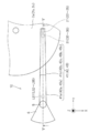
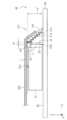
- FIG. 4 is a side view showing an example of the configuration of the first light guide unit 11 according to the first embodiment.
- FIG. 5 is a side view showing an example of the configuration of the first slider portion 31.
- FIG. 6 is a front view illustrating an example of the configuration of the light assist unit 51.
- FIG. 7 is a side view for explaining the detailed configuration of the optical waveguide 60.
- the first light guide unit 11 mainly includes a first light deflection unit 21 and a first slider unit 31.
- each of the second to fifth light deflection units 22 to 25 included in the second to fifth light guide units 12 to 15 is the first light deflection unit of the first light guide unit 11.
- 21 has the same hardware configuration.
- Each of the second to fifth slider portions 32 to 35 included in the second to fifth light guide units 12 to 15 has the same hardware as the first slider portion 31 of the first light guide unit 11. It has a configuration.
- the first light deflection unit 21 is provided on the opposite side of the first light source LS1 with the first slider portion 31 interposed therebetween, and mainly includes a reflection type diffraction grating 21a and a main body. Part 21b.
- the first light deflection unit 21 deflects the light emitted from the first light source LS1 by the diffraction grating 21a.
- the main body portion 21 b has a substantially trapezoidal shape when viewed from the side, and is formed of, for example, resin.
- the main body 21b functions as a prism that refracts incident light.
- the diffraction grating 21a is provided so as to face the light assist portion 51, and has a plurality of substantially serrated grooves.
- the plurality of grooves are formed of the same resin as that of the main body portion 21b.
- a metal such as aluminum (Al) or silver (Ag) or a dielectric multilayer film reflective film 21c (hatched portion) is formed on the surface of each groove.
- the diffraction grating 21a not only diffracts the light incident from the first slider portion 31 side and reflected by each groove (more specifically, the reflection film 21c) of the diffraction grating 21a, but also from the other end 46 side.
- Light incident on the main body 21b of the first light deflection unit 21 and reflected by each groove of the diffraction grating 21a can also be diffracted.
- the diffracted light L1 diffracted by the diffraction grating 21a is folded back to the first slider portion 31 side.
- the first light deflection unit 21 and the first slider unit 31 are disposed on the suspension unit 41b of the first arm unit 41 so as to face the same recording surface 3a of the first recording disk 2a. It is attached. That is, it is not necessary to dispose the first light deflection unit 21 in a space on the opposite side of the first recording disk 2a with the first arm unit 41 interposed therebetween. Therefore, space saving near the first arm portion 41 can be realized.
- the first light deflection section 21 is attached to the suspension section 41b of the first arm section 41 as shown in FIG. 4, but is not limited to this.
- the first light deflection unit 21 may be attached to the first slider unit 31.
- the first light deflection unit 21 can be attached to the first slider unit 31 by, for example, a member that connects the side surfaces so as not to obstruct the optical path.
- the groove shape of the diffraction grating 21a is not limited to a substantially sawtooth shape but may be a substantially sinusoidal shape or a rectangular shape (a shape similar to a grating coupler 68 described later).
- the first light deflecting unit 21 is configured such that the diffraction grating 21a is disposed at an appropriate position, and the inclination of the grating surface of the diffraction grating 21a is controlled, so that (1) Of the diffracted light diffracted by the diffraction grating 21a, The 0th-order light L0 travels farther than the light assist portion 51 as viewed from the first light deflection portion 21, reaches the first recording disk 2a farther than the light assist portion 51, and (2 ) Of the diffracted light diffracted by the diffraction grating 21a, light other than the 0th-order light (at least the first-order light) is set so as to enter the grating coupler 68 of the light assist unit 51.
- the position P11 (first position) indicates the arrival position where the light Li emitted from the first light source LS1 reaches the diffraction grating 21a.
- the position P12 (second position) indicates the lower end position of the light assist unit 51.
- the absolute value of the Z-axis component (vertical component) of the vector connecting the positions P11 and P12 is “a 1 ”
- the absolute value of the Y-axis component (horizontal component) of the vector connecting the positions P11 and P12 is “d 1 ”, Respectively.
- the 0th-order light L0 diffracted by the diffraction grating 21a does not hit the light assist unit 51 and is farther from the light assist unit 51 (particularly, the first order light L0). It can be used as illumination light for illuminating the recording disk 2a), and the 0th-order light L0 is effectively utilized.
- the traveling direction of the 0th-order light L0 diffracted by the diffraction grating 21a is the wavelength of the light Li emitted from the first light source LS1. Regardless, it is constant. Therefore, even when the wavelength of the light Li emitted from the first light source LS1 changes due to a change in the ambient temperature, the arrival position of the 0th-order light L0 on the first recording surface 3a is not affected by the wavelength change. , Become constant.
- the mounting adjustment of the first light deflection unit 21 and the first light source LS1 is performed. Performed accurately and easily.
- the first slider portion 31 functions as an optical head that irradiates light onto the opposing first recording surface 3a and magnetism for reading and writing magnetic information recorded on the opposing first recording surface 3a. And a function as a head.
- the first slider portion 31 mainly includes an optical assist portion 51, a magnetic recording portion 52, and a magnetic reproducing portion 53.
- the magnetic reproducing unit 53, the magnetic recording unit 52, the optical assist unit 51, and the first optical deflection unit 21 are directed from one end 45 to the other end 46 of the first arm unit 41. These are provided in this order along the arrangement direction mC.
- the light assist unit 51 places the diffracted light L1 folded back by the first light deflection unit 21 at a desired position on the first recording surface 3a in order to locally apply thermal energy to the first recording surface 3a. Irradiate. As shown in FIG. 6, the light assist part 51 has an optical waveguide 60.
- the optical waveguide 60 has the same configuration as a waveguide type solid immersion mirror (PSIM) disclosed in Patent Document 1.
- the optical waveguide 60 mainly includes a grating coupler 68, and transmits the light L1 emitted from the first light source LS1 and incident through the grating coupler 68. As shown in FIGS. 5 and 6, the optical waveguide 60 is provided on the side of the substrate 50 that faces the diffraction grating 21 a of the first light deflection unit 21.
- the optical waveguide 60 is formed by laminating a lower cladding layer 60c, a core layer 60b, and an upper cladding layer 60a in this order along the arrangement direction mC.
- the core layer 60b is formed of a material (for example, Ta 2 O 5 ) having a higher refractive index than the clad layers 60a and 60c (for example, formed of SiO 2 ). Thereby, the light guided to the optical waveguide 60 is totally reflected between the core layer 60b and the cladding layers 60a and 60c.
- the size (thickness) of the optical waveguide 60 in the Y-axis direction is small (thin). Furthermore, the inner surfaces 70 and 72 of the optical waveguide 60 have a parabolic shape, and the size of the optical waveguide 60 in the X-axis direction (the width of the optical waveguide 60) gradually increases from the grating coupler 68 toward the emission end 62. The shape of the optical waveguide 60 in the vertical section is narrowed and tapered.
- the light 64 introduced into the optical waveguide 60 and transmitted is totally reflected by the inner surfaces 70 and 72 and is condensed as it approaches the emission end 62.
- Near-field light is emitted from the emission end 62. Therefore, a minute light spot is formed on the first recording surface 3a of the first recording disk 2a, and a minute region on the first recording surface 3a is heated.
- the grating coupler 68 is a diffraction grating having a rectangular cross section.
- the grating coupler 68 has a function as an optical coupler, and guides the diffracted light L ⁇ b> 1 turned back by the diffraction grating 21 a of the first light deflection unit 21 into the optical waveguide 60.
- the grating coupler 68 is provided on the upper side surface of the optical waveguide 60. As shown in FIG. 7, the grating coupler 68 is formed of the same material as that of the core layer 60b, and is formed as a plurality of protruding portions protruding toward the upper cladding layer 60a.
- the magnetic recording unit 52 has a magnetic recording element (not shown), and is irradiated from the optical waveguide 60 of the light assist unit 51 in the first recording surface 3 a irradiated with light locally by the light assist unit 51. Magnetic information is newly written or rewritten in the portion where the light has reached.
- the magnetic reproducing unit 53 has a magnetic reproducing element (not shown) and reads magnetic information recorded on the first recording surface 3a.
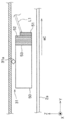
- FIG. 8 is a side view for explaining the diffracted light diffracted by the diffraction grating 21 a of the first light deflecting unit 21.
- the wavelength change of the light emitted from the first to fifth light sources LS1 to LS5 the diffraction angles of the first to fifth light deflectors 21 to 25, and the first to fifth light sources 21 to 25 are described.
- a relationship between the incident angles of the fifth slider portions 31 to 35 to the optical waveguide 60 will be described.
- each of the second to fifth light sources LS2 to LS5 has a hardware configuration similar to that of the first light source LS1.
- Each of the second to fifth light deflection units 22 to 25 has a hardware configuration similar to that of the first light deflection unit 21.
- each of the second to fifth slider portions 32 to 35 has a hardware configuration similar to that of the first slider portion 31.
- an arrow AR2 indicates the arrangement direction of each groove of the diffraction grating 21a.
- the normal line NL (two-dot chain line) of the diffraction grating 21a intersects the arrow AR2 perpendicularly on the YZ plane.
- the light Li indicates the light emitted from the first light source LS1 (see FIGS. 2 and 3).
- Light (0th-order diffracted light) L0 and light (diffracted light other than 0th-order light) L1 indicate light that is reflected and diffracted by the reflective film 21c of each groove.
- the wavelength of the light emitted from the first light source LS1 is “ ⁇ ”, and the incident angle of the light emitted from the first light source LS1 and incident on the diffraction grating 21a (the angle formed by the light Li and the normal NL).
- the diffraction order is “q”
- the diffraction angle of the diffracted light of q order (where q is an integer other than “0”) diffracted by the diffraction grating 21 a (between the light L1 and the normal line NL).
- the traveling direction of the diffracted light L1 moves from the normal line NL side to the light Li side, and rotates in the arrow R2 direction.
- the traveling direction of the diffracted light L1 moves from the light Li side to the normal NL side and rotates in the direction opposite to the arrow R2.
- the traveling direction of the diffracted light L1 (light other than the 0th-order light) diffracted by the diffraction grating 21a of the first light deflecting unit 21 varies according to the wavelength change of the light emitted from the first light source LS1. To do.
- the angle ⁇ 0 indicates the incident angle of the diffracted light L 1 that is diffracted by the first light deflecting unit 21 and enters the upper cladding layer 60 a.
- the angle theta c indicates the incident angle of the diffracted light L1 incident on the core layer 60b.
- the distance da indicates the interval (grating interval) between the protruding portions of the grating coupler 68.
- the refractive index of each cladding layer 60a, 60c is “n 0 ”
- the refractive index of the core layer 60b is “n c ”
- the waveguide mode (light is transmitted between the core layer 60b and the cladding layers 60a, 60c).
- "n eff" the effective refractive index in the traveling mode) in the core layer 60b with total reflection, when the wavelength of light incident on the grating coupler 68 to a " ⁇ ", the diffraction order "q", the formula (4) Is established.
- the incident angle ⁇ 0 that satisfies Expression (4) is the incident angle at which the coupling efficiency to the grating coupler 68 is maximized.
- the refractive index n 0 of the upper and lower cladding layers 60a and 60c is “1.47”, and the effective refractive index n eff in the waveguide mode is “1.72”. 6)
- the diffraction order q is an integer smaller than “0”.
- the wavelength ⁇ of the diffracted light L1 is decreased, the value in the braces of the equation (5) is increased, and the incident angle (optimum incident angle) ⁇ 0 is increased. That is, when the wavelength ⁇ of the diffracted light L1 decreases, the traveling direction of the diffracted light L1 moves in the direction opposite to the arrow R1.
- the traveling direction of the diffracted light L1 diffracted by the diffraction grating 21a corresponds to the fluctuation of the optimum incident angle.
- the traveling direction of the diffracted light L1 varies in the direction of the arrow R2 (see FIG. 8), and the variation direction of the optimum incident angle (the direction of the arrow R1: This corresponds to FIG.
- the optimum incidence angle the incident angle theta 0 of the diffracted light L1 incident on the grating coupler 68 of the optical waveguide 60 including the allowable range (optimum incidence angle ⁇ 0. 1 degree). That is, the diffraction grating 21a of the first light deflection unit 21 can absorb the influence of the wavelength change of the light from the first light source LS1.
- the light assist unit 51 can irradiate the first recording surface 3a with good spot light, and can be fine.
- the region can be heated.
- the diffraction grating 21a of the first light deflection unit 21 of the first embodiment can absorb the influence of the wavelength change of the light from the first light source LS1. Therefore, even when the wavelength ⁇ of the light Li from the first light source LS1 is changed, the light assist unit 51 can irradiate the first recording surface 3a with good spot light, and can be fine. The region can be heated.
- the angle ⁇ 1 (see FIG. 4) formed by the light Li emitted from the first light source LS1 and the 0th-order light L0 diffracted by the diffraction grating 21a satisfies the condition of Expression (1), 0
- the next light L0 travels farther than the light assist portion 51 and reaches the first recording disk 2a. Therefore, the 0th-order light L0 diffracted by the diffraction grating 21a can be used as illumination light for illuminating the first recording disk 2a, and the 0th-order light L0 can be used effectively.
- the arrival position of the 0th-order light L0 on the first recording surface 3a is not affected by the wavelength change. It becomes constant. Therefore, the attachment position of the first light source LS1 and the first light deflection unit 21 is accurately adjusted by detecting the arrival position of the zero-order light L0 on the first recording surface 3a and adjusting the arrival position to be a predetermined position. And can be implemented easily.
- the information recording apparatus 100 according to the second embodiment is the same as the information recording apparatus 1 according to the first embodiment, except that the hardware configuration of the light guide unit is different from that of the information recording apparatus 1 according to the first embodiment. It is the same. Therefore, in the following, this difference will be mainly described.
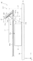
- FIG. 9 is a side view showing an example of the configuration of the first light guide unit 111 in the second embodiment.
- the first light guide unit 111 mainly includes a first slider portion 31 and a first light deflection portion 121.
- the first light deflector 121 folds the light Li emitted from the first light source LS1 toward the first slider 31 similarly to the first light deflector 21.
- the tip (other end) 46 of the suspension part 41b is bent downward, and the shape of the suspension part 41b is substantially L-shaped in side view.
- the first light deflection unit 121 is fixed to the lower end 46 of the suspension portion 41b formed by bending with a resin adhesive or the like.
- the first light deflector 121 is formed as a reflective diffraction grating 21a (diffraction grating mirror). That is, unlike the first light deflection unit 21 of the first embodiment, the first light deflection unit 121 does not have the main body 21b. Therefore, the member attached near the other end 46 of the first arm portion 41 can be reduced in weight, and the load applied to the first arm portion 41 can be reduced.
- the diffraction grating 21a of the first light deflection unit 121 of the second embodiment is similar to the first light deflection unit 21 of the first embodiment in the wavelength of light from the first light source LS1.
- the effects of change can be absorbed. Therefore, even when the wavelength ⁇ of the light Li from the first light source LS1 is changed, the light assist unit 51 can irradiate the first recording surface 3a with good spot light, and can be fine. The region can be heated.
- the angle ⁇ 1 (see FIG. 9) formed by the light Li emitted from the first light source LS1 and the 0th-order light L0 diffracted by the diffraction grating 21a satisfies the condition of Expression (1), 0
- the next light L0 travels farther than the light assist portion 51 and reaches the first recording disk 2a. Therefore, the 0th-order light L0 diffracted by the diffraction grating 21a can be used as illumination light for illuminating the first recording disk 2a, and the 0th-order light L0 can be used effectively.
- the arrival position of the 0th-order light L0 on the first recording surface 3a is not affected by the wavelength change. , Become constant. Therefore, the attachment position of the first light source LS1 and the first light deflection unit 21 is accurately adjusted by detecting the arrival position of the zero-order light L0 on the first recording surface 3a and adjusting the arrival position to be a predetermined position. And can be implemented easily.
- the first light deflection unit 121 of the second embodiment does not have a main body 21b. Therefore, the member attached near the other end 46 of the first arm portion 41 can be reduced in weight, and the load applied to the first arm portion 41 can be reduced.
- the information recording apparatus 200 according to the third embodiment is the same as the information recording apparatus 1 according to the first embodiment, except that the hardware configuration of the light guide unit is different from that of the information recording apparatus 1 according to the first embodiment. It is the same. Therefore, in the following, this difference will be mainly described.
- FIG. 10 is a side view showing an example of the configuration of the first light guide unit 211 in the third embodiment.
- the first light guide unit 211 mainly includes a first slider portion 31 and a first light deflection portion 221.
- the first light deflection unit 221 has a hardware configuration similar to that of the first light deflection unit 21 of the first embodiment, and the light Li emitted from the first light source LS1 is transmitted to the first slider unit 31 side. Wrap around.
- the first light deflection unit 221 is disposed on the opposite side of the first slider unit 31 with the first arm unit 41 interposed therebetween.
- the light other than the 0th-order light L0 and the 0th-order light (at least the first-order light) diffracted by the diffraction grating 21a of the first light deflector 221 is the suspension part of the first arm part 41. It reaches the optical waveguide 60 side of the light assist part 51 through the through hole 221b provided in 41b.
- the first light deflection unit 221 it is not necessary to arrange the first light deflection unit 221 in a narrow space between the first arm unit 41 and the first recording disk 2a (interval: 0.5 mm or less). Therefore, the degree of freedom of attachment of the first light deflection unit 221 can be increased. Moreover, the attachment position of the 1st light deflection
- the diffraction grating 21a of the first light deflection unit 221 according to the third embodiment is similar to the first light deflection unit 21 according to the first embodiment in the wavelength of light from the first light source LS1.
- the effects of change can be absorbed. Therefore, even when the wavelength ⁇ of the light Li from the first light source LS1 is changed, the light assist unit 51 can irradiate the first recording surface 3a with good spot light, and can be fine. The region can be heated.
- the angle ⁇ 1 (see FIG. 10) formed by the light Li emitted from the first light source LS1 and the 0th-order light L0 diffracted by the diffraction grating 21a satisfies the condition of Expression (1), 0
- the next light L0 travels farther than the light assist portion 51 and reaches the first recording disk 2a. Therefore, the 0th-order light L0 diffracted by the diffraction grating 21a can be used as illumination light for illuminating the first recording disk 2a, and the 0th-order light L0 can be used effectively.
- the arrival position of the 0th-order light L0 on the first recording surface 3a is not affected by the wavelength change. , Become constant. Therefore, the attachment position of the first light source LS1 and the first light deflection unit 21 is accurately adjusted by detecting the arrival position of the zero-order light L0 on the first recording surface 3a and adjusting the arrival position to be a predetermined position. And can be implemented easily.
- the first light deflection unit 221 of the third embodiment is disposed on the opposite side of the first slider unit 31 with the first arm unit 41 interposed therebetween, and is diffracted by the first light deflection unit 221.
- the light reaches the optical waveguide 60 side of the light assist portion 51 through the through hole 221b of the suspension portion 41b.
- the degree of freedom of attachment of the first light deflection unit 221 can be increased, and the attachment position of the first light deflection unit 221 can be easily adjusted.
- the information recording apparatus 300 according to the fourth embodiment is the same as that of the information recording apparatus 200 according to the third embodiment, except that the hardware configuration of the light guide unit is different. It is the same. Therefore, in the following, this difference will be mainly described.
- FIG. 11 is a side view showing an example of the configuration of the first light guide unit 311 in the fourth embodiment.
- the first light guide unit 311 mainly includes a first slider portion 31 and a first light deflection portion 321.
- the first light deflection unit 321 has a hardware configuration similar to that of the first light deflection unit 121 of the second embodiment, and the light Li emitted from the first light source LS1 is transmitted to the first slider unit 31 side. Wrap around.
- the first light deflection unit 321 is disposed on the opposite side of the first slider unit 31 with the first arm unit 41 interposed therebetween. Further, as shown in FIG. 11, the light other than the 0th order light L0 and the 0th order light (at least the first order light) diffracted by the diffraction grating 21a of the first light deflector 321 is the suspension part of the first arm part 41. It reaches the optical waveguide 60 side of the light assist part 51 through the through hole 221b provided in 41b.
- the first light deflection unit 221 it is not necessary to arrange the first light deflection unit 221 in a narrow space between the first arm unit 41 and the first recording disk 2a. Therefore, the degree of freedom of attachment of the first light deflection unit 221 can be increased. Moreover, the attachment position of the 1st light deflection
- the first light deflection unit 321 of the fourth embodiment does not have a main body 21b. Therefore, the member attached near the other end 46 of the first arm portion 41 can be reduced in weight, and the load applied to the first arm portion 41 can be reduced.
- the diffraction grating 21a of the first light deflection unit 321 according to the fourth embodiment is similar to the first light deflection unit 21 according to the first embodiment in the wavelength of light from the first light source LS1.
- the effects of change can be absorbed. Therefore, even when the wavelength ⁇ of the light Li from the first light source LS1 is changed, the light assist unit 51 can irradiate the first recording surface 3a with good spot light, and can be fine. The region can be heated.
- the angle ⁇ 1 (see FIG. 11) formed by the light Li emitted from the first light source LS1 and the 0th-order light L0 diffracted by the diffraction grating 21a satisfies the condition of Expression (1), 0
- the next light L0 travels farther than the light assist portion 51 and reaches the first recording disk 2a. Therefore, the 0th-order light L0 diffracted by the diffraction grating 21a can be used as illumination light for illuminating the first recording disk 2a, and the 0th-order light L0 can be used effectively.
- the arrival position of the 0th-order light L0 on the first recording surface 3a is not affected by the wavelength change. , Become constant. Therefore, the attachment position of the first light source LS1 and the first light deflection unit 21 is accurately adjusted by detecting the arrival position of the zero-order light L0 on the first recording surface 3a and adjusting the arrival position to be a predetermined position. And can be implemented easily.
- the first light deflection unit 321 according to the fourth embodiment is disposed on the opposite side of the first slider unit 31 with the first arm unit 41 interposed therebetween, and is diffracted by the first light deflection unit 321.
- the light reaches the optical waveguide 60 side of the light assist portion 51 through the through hole 221b of the suspension portion 41b. Thereby, it is not necessary to arrange the first light deflection section 321 in a narrow space between the first arm section 41 and the first recording disk 2a. Therefore, the degree of freedom of attachment of the first light deflection unit 321 can be increased.
- the first light deflecting unit 321 according to the fourth embodiment does not have the main body portion 21b, like the first light deflecting unit 121 according to the second embodiment. Therefore, the member attached near the other end 46 of the first arm portion 41 can be reduced in weight, and the load applied to the first arm portion 41 can be reduced.
- the information recording apparatus 400 in the fifth embodiment is the same as that in the first embodiment except that the hardware configuration of the light guide unit is different from that of the information recording apparatus 1 in the first embodiment. It is the same. Therefore, in the following, this difference will be mainly described.
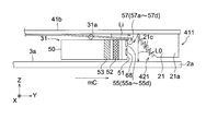
- FIG. 12 is a side view showing an example of the configuration of the first light guide unit 411 according to the first embodiment.
- FIG. 13 is a side view showing an example of the configuration of the first light deflection unit 421.
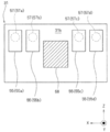
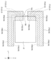
- 14 and 15 are a front view and a plan view showing an example of the configuration of the first slider portion 31, respectively.
- the first light guide unit 411 mainly includes a first light deflection unit 421, a first slider unit 31, and an FPC (Flexible Printed Circuits) 56. Yes.
- FPC Flexible Printed Circuits
- each of the second to fifth light deflection units 22 to 25 included in the second to fifth light guide units 12 to 15 is the first light deflection unit of the first light guide unit 411.
- 421 has the same hardware configuration.
- Each of the second to fifth slider portions 32 to 35 included in the second to fifth light guide units 12 to 15 has the same hardware as the first slider portion 31 of the first light guide unit 411. It has a configuration.
- the first light deflection unit 421 deflects the light emitted from the first light source LS1 by the diffraction grating 21a and introduces it to the light assist unit 51 of the first arm unit 41.
- the first light deflection unit 421 is provided on the opposite side of the first light source LS1 across the first slider unit 31, and mainly includes a reflective diffraction grating 21a and a main body. Part 21b.
- the main body 21b has a substantially trapezoidal shape when viewed from the side, and is made of, for example, glass or resin.
- the diffraction grating 21a is provided so as to face and oppose the light assist portion 51 of the first arm portion 41, and has a plurality of substantially serrated grooves.
- the plurality of grooves are formed of the same material (for example, glass or resin) as the main body portion 21b.
- a reflective film 21c and an insulating film 21g are laminated on the surface of each groove in this order from the main body portion 21b toward the grating coupler 68 of the light assist portion 51. Note that the diffraction grating 21a and the light assist portion 51 are arranged close to each other because the optimum incident angle ⁇ 0 (see FIG. 7) of the light incident on the grating coupler 68 of the light assist portion 51 is previously set. This is because it is set.
- the reflective film 21c (hatched portion) is formed of a metal such as aluminum (Al) or silver (Ag), or a dielectric.
- the insulating film 21g has an electrical resistivity such as an insulating material (for example, magnesium fluoride (MgF 2 ), calcium fluoride (CaF 2 ), silicon dioxide (SiO 2 ), titanium dioxide (TiO 2 ), or the like.
- MgF 2 magnesium fluoride
- CaF 2 calcium fluoride
- SiO 2 silicon dioxide
- TiO 2 titanium dioxide
- ⁇ ⁇ m is 10 6 (10 6) or more).
- the surface of the diffraction grating 21a is coated with an insulating material to be an insulator.
- the diffraction grating 21a diffracts the light Li that is incident from the first light source LS1 side and reaches each groove (more specifically, the reflective film 21c) of the diffraction grating 21a, and moves toward the first slider portion 31 side. Can be folded.
- the diffraction grating 21 a functions as a light deflection unit that deflects (diffracts) the incident light Li toward the first slider unit 31.
- first light deflecting unit 421 the first slider unit 31, the diffraction grating 21a, the optical assist unit 51, the optical waveguide 60, and the grating coupler 68 are the same as those in the first embodiment, and thus description thereof is omitted. To do.
- a plurality (four in this embodiment) of electrodes 55 (55a to 55d) are opposed to the first light deflector 421 on the side surface of the first slider portion 31, as shown in FIGS. It is provided on the surface 31b.
- the FPC 56 (56a, 56b) electrically connects the head signal control unit 9 and the electrode 55 (55a to 55d) of the first slider unit 31.
- the FPC 56a includes metal balls 57a and 57b and conductor foils (for example, copper foils) 58a and 58b.
- the FPC 56b includes metal balls 57c and 57d and conductor foils (for example, copper foils) 58c and 58d.
- each FPC 56 (56a, 56b) is created by adhering the above-described conductor foil 58 (58a-58d) on a film-like insulator (for example, polyimide).
- the metal spheres 57 are metal spheres connected to the ends of the corresponding conductor foils 58 (58a to 58d). As shown in FIGS. 14 and 15, each metal ball 57 (57a to 57d) is connected to the corresponding electrode 55 (55a to 55d) by, for example, thermocompression bonding. Therefore, the FPC 56 and the metal sphere 57 constitute a wiring member that electrically connects the electrode 55 of the first slider portion 31 and the head signal control portion 9.
- the first slider unit 31 having the light assist unit 51 and the magnetic recording unit 52 performs light irradiation based on the light L1 on the minute region of the first recording disk 2a, and the minute region on the minute region. Corresponding magnetic information can be rewritten.
- the first light deflector 421 is provided with a reflective diffraction grating 21 a, and the optical waveguide 60 is provided with a grating coupler 68.
- the incident angle of light L1 (0 non-order diffracted light) is incident on the grating coupler 68 of the optical waveguide 60, the allowable range including the optimum incidence angle theta 0 Can be maintained within (optimal incident angle ⁇ 0.1 degree). That is, the diffraction grating 21a of the first light deflection unit 421 can absorb the influence of the wavelength change of the incident light Li.
- the light assist unit 51 can irradiate the first recording surface 3a with good spot light, It is possible to heat the minute region satisfactorily.
- the surface of the diffraction grating 21a is coated with an insulating material and is an insulator. Therefore, it is possible to prevent a short circuit from occurring between the electrode 55, the FPC 56, the metal sphere 57, and the first light deflection unit 421. Therefore, it is possible to prevent the first light deflection unit 421 and the first slider unit 31 from being damaged due to an electrical adverse effect.
- the surface of the diffraction grating 21a is coated with an insulating material. Therefore, the durability of the diffraction grating 21a can be improved.
- the information recording apparatus 500 in the sixth embodiment has a hardware configuration similar to that of the first optical deflection section (and the first optical deflection section) compared to the information recording apparatus 400 of the fifth embodiment.
- the second embodiment is the same as the fifth embodiment except that the hardware configuration of the second to fifth light deflection units is different. Therefore, in the following, this difference will be mainly described.
- FIG. 16 is a side view showing an example of the configuration of the first light deflection unit 521 in the sixth embodiment.
- the components corresponding to the second to fifth light deflection units have the same hardware configuration as that of the first light deflection unit 521. Therefore, only the first light deflection unit 521 will be described below.
- the first light deflection unit 521 deflects the light Li emitted from the first light source LS ⁇ b> 1 by the reflecting mirror 121 f and introduces it into the light assist unit 51 of the first arm unit 41.
- the first light deflector 521 mainly includes a reflecting mirror 121f and a main body 21b.
- the reflecting mirror 121f is a plane mirror whose reflecting surface is substantially flat. As shown in FIG. 16, on the surface of the reflecting mirror 121f, a reflecting film 121c and an insulating film 121g are laminated in this order from the main body portion 21b toward the grating coupler 68 of the light assist portion 51.
- the reflective film 121c (hatched portion) is formed of a metal such as aluminum (Al) or silver (Ag), or a dielectric.
- the insulating film 121g has an electrical resistivity such as an insulating material (for example, magnesium fluoride (MgF 2 ), calcium fluoride (CaF 2 ), silicon dioxide (SiO 2 ), titanium dioxide (TiO 2 ), or the like.
- MgF 2 magnesium fluoride
- CaF 2 calcium fluoride
- SiO 2 silicon dioxide
- TiO 2 titanium dioxide
- ⁇ ⁇ m is 10 6 (10 6) or more). That is, the surface of the reflecting mirror 121f is coated with an insulating material and is an insulator.
- the reflecting mirror 121f can reflect the light Li incident from the first light source LS1 side by the reflecting mirror 121f and fold it back to the first slider portion 31 side. That is, the reflecting mirror 121 f functions as a light deflecting unit that deflects (reflects) the incident light Li toward the first slider unit 31.
- the reflecting mirror 121f is not limited to a plane mirror, and may be a convex or concave spherical mirror or a parabolic mirror.
- the surface of the reflecting mirror 121f is coated with an insulating material and is an insulator. Therefore, it is possible to prevent a short circuit from occurring between the electrode 55, the FPC 56, the metal sphere 57, and the first light deflection unit 521. Therefore, it is possible to prevent the first light deflection unit 521 and the first slider unit 31 from being damaged due to an electrical adverse effect.
- the surface of the reflecting mirror 121f is coated with an insulating material. Therefore, the durability of the reflecting mirror 121f can be improved.
- the surfaces of the diffraction grating 21a and the reflecting mirror 121f are described as being coated with an insulating material, but the present invention is not limited to this.
- the diffraction grating 21a and the reflecting mirror 121f may be formed of a dielectric.
- the entire first light deflecting portions 421 and 521 (not only the diffraction grating 21a and the reflecting mirror 121f but also the main body portion 21b) may be formed of a dielectric. Also in this case, it is possible to prevent a short circuit from occurring between the electrode 55, the FPC 56, the metal ball 57, and the first deflecting units 421 and 521.
- the surfaces of the diffraction grating 21a and the reflecting mirror 121f are insulators, but the measures for preventing a short circuit are limited to this. Not a thing.
- the surfaces of the electrodes 55 (55a to 55d) and the metal spheres 57 (57a to 57d) may be insulators.
- the surfaces of the electrodes 55 (55a to 55d) and the metal spheres 57 (57a to 57d) may be insulators. Also in these cases, it is possible to prevent the first light deflection unit 421 and the first slider unit 31 from being damaged due to an adverse electrical effect.
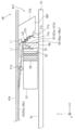
- FIG. 17 is a side view showing an example of the configuration of the first light guide unit 511 in the present embodiment.
- FIG. 18 is a side view showing an example of the configuration of the first light deflection unit 621.
- FIG. 19 is a plan view showing an example of the configuration of the first slider portion 31.
- the first light guide unit 511 mainly includes a first light deflection unit 621, a first slider unit 31, and an FPC 56.
- each of the second to fifth light deflection units 22 to 25 included in the second to fifth light guide units 12 to 15 is the first light deflection unit of the first light guide unit 511.
- 621 has the same hardware configuration.
- Each of the second to fifth slider portions 32 to 35 included in the second to fifth light guide units 12 to 15 has the same hardware as the first slider portion 31 of the first light guide unit 511. It has a configuration.
- the first light deflection unit 621 deflects the light emitted from the first light source LS1 by the diffraction grating 621a and introduces the light into the light assist unit 51 of the first arm unit 41.
- the first light deflection unit 621 is provided on the opposite side of the first light source LS1 across the first slider unit 31, and mainly includes a reflective diffraction grating 621a and a main body. It has a part 621b and a protruding part 621d.
- the main body portion 621 b is a block body having a substantially parallelogram in a side view, and is formed of, for example, glass or resin.
- side view in the present embodiment refers to a case where the YZ plane is viewed in the negative direction of the X axis.
- the diffraction grating 621 a is provided so as to face and oppose the light assist portion 51 of the first arm portion 41. Further, as shown in FIG. 17, the diffraction grating 621a has a plurality of substantially serrated grooves.
- the plurality of grooves are formed of a material (for example, glass or resin) similar to that of the main body portion 621b.
- a reflective film 621c is laminated on the surface of each groove.
- the reflective film 621c (hatched portion) is made of a metal such as aluminum (Al) or silver (Ag), or a dielectric.
- the protruding portion 621d is a block body having a substantially parallelogram in side view, and is formed of the same material (for example, glass or resin) as the main body portion 621b. As shown in FIGS. 17, 18, and 19, the protruding portion 621d is provided so as to protrude from the vicinity of the center of the mounting surface 621e of the main body portion 621b toward the light assist portion 51. A diffraction grating 621a is formed on the surface of the protrusion 621d.
- the diffraction grating 621a formed on the surface of the protruding portion 621d is provided so as to protrude from the main body portion 621b into the non-interference space 31c.
- the diffraction grating 621a protrudes from the vicinity of the center of the mounting surface 621e in plan view (when the XY plane is viewed in the negative Z-axis direction) toward the first slider portion 31.
- the diffraction grating 621 a protrudes from the vicinity of the center of the mounting surface 621 e in the side view toward the first slider portion 31.
- non-interference space 31c is provided even when the first slider portion 31 floats, the electrodes 55 (55a to 55d), the FPCs 56 (56a, 56b), and the metal balls 57 (57a) of the first slider portion 31. To 57d) are determined in advance as spaces that do not enter.
- the information recording apparatus 1 prevents the interference between the electrodes 55 (55a to 55d), the FPCs 56 (56a and 56b), the metal spheres 57 (57a to 57d), and the diffraction grating 621a, and the diffraction grating 621a. Can be brought close to the light assist portion 51 of the first slider portion 31. Therefore, the light L1 can be satisfactorily introduced into the light assist part 51 without affecting the flying characteristics of the first slider part 31, and the magnetic information is good with respect to the first recording disk 2a. Can be recorded.
- the surface of the protruding portion 621d and the mounting surface 621e of the main body portion 621b are set to be substantially parallel.
- the inclination (angle) of the surface of the protruding portion 621 d with respect to the facing surface 31 b of the first slider portion 31 is set in advance based on the optimum incident angle ⁇ 0 of light incident on the grating coupler 68.
- the diffraction grating 621a diffracts the light Li that enters from the first light source LS1 side and reaches each groove (more specifically, the reflective film 621c) of the diffraction grating 621a, and moves it toward the first slider portion 31 side. Can be folded. That is, the diffraction grating 621 a functions as a light deflection unit that deflects (diffracts) the incident light Li toward the first slider unit 31.
- the first light deflection unit 621 and the first slider unit 31 are placed on the suspension unit 41b of the first arm unit 41 so as to face the same recording surface 3a of the first recording disk 2a. It is attached. That is, it is not necessary to arrange the first light deflecting unit 621 in the space opposite to the first recording disk 2a with the first arm unit 41 interposed therebetween. Therefore, space saving near the first arm portion 41 can be realized.
- the groove shape of the diffraction grating 621a is not limited to a substantially sawtooth shape, but may be a substantially sine wave shape or a rectangular shape (a shape similar to a grating coupler 68 described later).
- the first slider portion 31 functions as an optical head that irradiates light onto the opposing first recording surface 3a and magnetism for reading and writing magnetic information recorded on the opposing first recording surface 3a. And a function as a head.
- the configuration of the first slider unit 31, the configuration of the light assist unit 51 and the FPC 56, and the operation are the same as described above, and will be omitted.
- the diffraction grating 621a formed on the surface of the protruding portion 621d is provided so as to protrude from the main body portion 621b to the non-interference space 31c.
- the information recording apparatus 1 prevents the interference between the electrodes 55 (55a to 55d), the FPCs 56 (56a and 56b), the metal spheres 57 (57a to 57d), and the diffraction grating 621a, and the diffraction grating 621a.
- the protruding portion 621d is assumed to be provided so as to protrude from the vicinity of the center of the mounting surface 621e of the main body portion 621b toward the light assist portion 51.
- the shape and attachment method of the protrusion 621d are not limited to this.
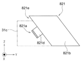
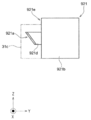
- 20 to 22 are side views showing the configurations of the first light deflection units 721, 821, and 921. FIG. As shown in FIGS.
- the shape of the first light deflection unit 721 in a side view is substantially L-shaped, and the protrusion 721d and the diffraction grating 721a are located below the mounting surface 721e (head facing surface). Projecting from the vicinity toward the first slider portion 31.
- the diffraction grating 721a formed on the protruding portion 721d is common to the diffraction grating 621a of the protruding portion 621d in that it protrudes from the vicinity of the center of the mounting surface 621e in plan view toward the first slider portion 31.
- the diffraction grating 721a is different from the attachment surface 621e in the positional relationship with the attachment surface 621e in a side view.
- the information recording apparatus 1 in which the first light deflecting units 721, 821, and 921 are employed also has good light L 1 with respect to the light assist unit 51 without affecting the flying characteristics of the first slider unit 31. And magnetic information can be satisfactorily recorded on the first recording disk 2a.
- the diffraction grating 621a has been described as being used as an optical deflection unit, but the present invention is not limited to this.
- a reflecting mirror may be used as the light deflection unit.
- the reflecting mirror is not limited to a plane mirror but may be a convex or concave spherical mirror or a parabolic mirror.
Landscapes
- Physics & Mathematics (AREA)
- Optics & Photonics (AREA)
- Electromagnetism (AREA)
- Engineering & Computer Science (AREA)
- Manufacturing & Machinery (AREA)
- Recording Or Reproducing By Magnetic Means (AREA)
Abstract
本発明は、光源から出射された光の利用効率を向上させることができる導光ユニットおよび、これを用いた情報記録装置を提供する。 第1導光ユニット11は、主として、第1光偏向部21と、第1スライダ部31と、を有している。第1光偏向部21は、第1スライダ部31を挟んで光源と逆側に設けられており、主として、反射型の回折格子21aを有している。第1光偏向部21は、光源から出射された光を回折格子21aにて偏向する。これにより、回折格子21aで回折される光のうち0次光は、光アシスト部51より遠方側の第1記録用ディスク2aに到達する。一方、回折格子21aで回折される光のうち少なくとも1次光は、光アシスト部51に到達し、光導波路のグレーティングカプラに入射する。
Description
本発明は、光源から出射された光を光導波路に導く導光ユニット、およびこの導光ユニットを用いた情報記録装置に関する。
従来より、光放射による熱アシスト方式の磁気情報記録技術が知られている(例えば、特許文献1)。特許文献1の磁気情報記録技術において、熱アシスト用の光は、集光機能付きプラナー導波路の下端から照射される。
ここで、熱アシスト方式の磁気情報記録技術では、記録密度を向上させるため、記録媒体として高保磁力媒体が使用されている。この高保磁力媒体は、高密度記録および熱安定性を両立できる記録媒体であり、高密度に記録された磁気情報(記録ビット)を長期間、安定して保存することができる。
また、熱アシスト方式の磁気情報記録技術では、磁気情報の書き換えに先立って、記録面に対して局所的に熱エネルギーが付与される。これにより、記録面に対して局所的に熱エネルギーが付与され、書き換え対象となる磁気情報の保磁力が小さくなる。そのため、記録媒体として高保磁力媒体が使用される場合であっても、書き換え対象となる磁気情報は容易に磁化反転させられ、磁気情報の書き換えが容易に実行される。
そして、光が照射された記録面の温度は、その後急速に下降し、記録面の保磁力は、元の高保磁力状態に戻る。そのため、書き換えられた磁気情報は、安定して保存されることになる。
しかしながら、特許文献1には、光源から集光機能付きプラナー導波路の回折格子に光を入射させる場合において、この回折格子に対して光を傾けて入射させることが記載されているのみで、光源からの光をどのように入射されるかという具体的な手法については記載されていない。
そこで、本発明では、光源から出射された光の利用効率を向上させることができる導光ユニットおよび、これを用いた情報記録装置を提供することを目的とする。
上記の課題を解決するため、請求項1の発明は、光源から出射された光を導く導光ユニットであって、グレーティングカプラを有するとともに、前記グレーティングカプラを介して入射する光を伝送する光導波路と、反射型の回折格子を有するとともに、前記光導波路を挟んで前記光源と逆側に設けられており、前記光源から出射された光を前記回折格子にて偏向する光偏向部とを備え、前記光偏向部は、前記回折格子で回折される回折光のうち、0次光が、前記光偏向部から見て前記光導波路よりも遠方に向かって進行し、前記回折格子で回折される回折光のうち、少なくとも1次光が、前記グレーティングカプラに入射する、ように設定されていることを特徴とする。
また、請求項2の発明は、請求項1に記載の導光ユニットにおいて、式(1)に従って、前記光源から出射された光と、前記回折格子で回折される前記0次光と、のなす角θ1が求められることを特徴とする。ただし、第1位置が、前記光源から出射された光が前記回折格子に到達する位置と、第2位置が、前記光導波路の下端位置と、それぞれ定義される場合において、a1は、前記第1および第2位置を結ぶベクトルの垂直成分の絶対値を示し、d1は、前記第1および第2位置を結ぶベクトルの水平成分の絶対値を示す。
また、請求項3の発明は、記録媒体に磁気情報を記録する情報記録装置であって、一方向に延伸するとともに、その延伸方向における一端付近に設けられた揺動軸を中心に揺動可能なアーム部と、前記延伸方向における前記アーム部の一端側から他端側に向かって光を出射する光源と、前記アーム部の他端付近に取り付けられており、前記光源から出射された光を伝送する光導波路と、前記記録媒体の記録面のうち、前記光導波路から照射された光が到達した部分について、磁気情報を新規に書き込み又は書き換える磁気記録部とを有するヘッド部と、前記アーム部の他端付近に取り付けられており、前記光源から出射された光を回折格子にて偏向する光偏向部とを備え、前記磁気記録部、前記光導波路、および前記光偏向部は、前記アーム部の一端から他端に向かって、この順番に設けられており、前記光導波路は、グレーティングカプラを有するとともに、前記グレーティングカプラを介して入射する光を伝送し、前記光偏向部は、前記回折格子で回折される回折光のうち、0次光が、前記光偏向部から見て前記光導波路よりも遠方の前記記録媒体に到達し、前記回折格子で回折される回折光のうち、少なくとも1次光が、前記グレーティングカプラに入射する、ように設定されていることを特徴とする。
また、請求項4の発明は、請求項3に記載の情報記録装置において、前記ヘッド部および前記光偏向部は、前記記録媒体の同一記録面と対向するように、前記アーム部に取り付けられていることを特徴とする。
また、請求項5の発明は、請求項3に記載の情報記録装置において、前記ヘッド部は、前記記録媒体と対向するように、前記アーム部に取り付けられ、前記光偏向部は、前記アーム部を挟んで前記ヘッド部と逆側に配置されるとともに、前記回折格子で回折される前記0次光および前記少なくとも1次光を、前記アーム部に設けられた貫通孔を介して前記光導波路側に到達させることを特徴とする。
また、請求項6の発明は、請求項3ないし請求項5のいずれかに記載の情報記録装置において、式(1)に従って、前記光源から出射された光と、前記回折格子で回折される前記0次光と、のなす角θ1が求められることを特徴とする。ただし、第1位置が、前記光源から出射された光が前記回折格子に到達する位置と、第2位置が、前記光導波路の下端位置と、それぞれ定義される場合において、a1は、前記第1および第2位置を結ぶベクトルの垂直成分の絶対値を示し、d1は、前記第1および第2位置を結ぶベクトルの水平成分の絶対値を示す。
請求項1および請求項2に記載の発明によれば、光源から出射された光は、光偏向部の回折格子で光導波路側に折り返される。そして、回折格子で回折される回折光のうち、少なくとも1次光が、光導波路のグレーティングカプラに入射され、0次光が光導波路よりも遠方に向かって進行する。そのため、回折格子で回折される0次光を、光導波路よりも遠方を照明する照明光として使用でき、0次光を有効活用できる。
一方、請求項3ないし請求項6に記載の発明によれば、アーム部の揺動軸(一端)側から他端側に出射された光は、光偏向部の回折格子にてヘッド部の光導波路側に折り返される。そして、回折格子で回折される回折光のうち、少なくとも1次光が光導波路のグレーティングカプラに入射され、0次光が光導波路よりも遠方の記録媒体に到達する。そのため、回折格子で回折される0次光を、記録媒体を照明する照明光として使用でき、0次光を有効活用できる。
また、請求項1ないし請求項6において、光源から出射される光の波長が変化すると、光偏向部の回折格子で回折される回折光(0次光を除く)の回折角は、この波長変化に応じて変動する。また、グレーティングカプラを介して光導波路に入射する光の適正入射角も、光源から出射される光の波長変化に応じて変動する。
これにより、適切な回折格子が選択されることによって、光源から出射される光の波長が変化した場合であっても、グレーティングカプラに入射する回折光の入射角は、適正入射角に維持される。すなわち、光偏向部の回折格子によって、波長変化の影響が吸収される。そのため、光源から出射される光の波長が変化した場合であっても、光導波路に対して回折光を良好に入射させることができる。
特に、請求項3ないし請求項6に記載において、回折格子で回折される0次光は、光偏向部から見て光導波路よりも遠方側の記録媒体に到達する。また、回折格子における0次光の回折角は、光源から出射される光の波長が変化しても変動しない。これにより、記録媒体に到達する0次光の到達位置は、波長変化の影響を受けない。そのため、記録媒体における0次光の到達位置が所定位置となるように調整することによって、光偏向部の取付調整を正確かつ容易に実行できる。
特に、請求項4に記載の発明によれば、ヘッド部および光偏向部は、記録媒体の記録面と対向するようにアーム部に取り付けられている。すなわち、アーム部を挟んで記録媒体と逆側の空間に光偏向部を配置する必要がない。そのため、アーム部付近の省スペース化を実現できる。
特に、請求項5に記載の発明によれば、ヘッド部と記録媒体との間の狭い空間に、光偏向部を配置する必要がない。そのため、光偏向部の取り付けの自由度を高めることができるとともに、光偏向部の取付位置を容易に調整することができる。
以下、図面を参照しつつ本発明の実施の形態について詳細に説明する。
<1.第1の実施の形態>
<1.1.情報記録装置の構成>
図1は、本実施の形態における情報記録装置1の構成の一例を模式的に示す斜視図である。情報記録装置1は、熱アシスト方式の磁気情報記録装置であり、いわゆるハードディスクドライブとして使用することができる。また、情報記録装置1の記録媒体としては、高保磁力媒体が用いられている。
<1.1.情報記録装置の構成>
図1は、本実施の形態における情報記録装置1の構成の一例を模式的に示す斜視図である。情報記録装置1は、熱アシスト方式の磁気情報記録装置であり、いわゆるハードディスクドライブとして使用することができる。また、情報記録装置1の記録媒体としては、高保磁力媒体が用いられている。
ここで、高保磁力媒体に記録されている磁気情報が書き換えられるとき、情報記録装置1は、高保磁力媒体の記録面に対して局所的に光を照射し、局所的に熱エネルギーを付与する。これにより、熱エネルギーが付与された領域(書換領域)の温度が上昇し、書換領域における磁気情報の保磁力が小さくなる。そのため、記録媒体として高保磁力媒体が使用される場合であっても、磁気情報の書き換えを容易に実行することができる。
そして、光放射に基づく熱エネルギーが付与された書換領域の温度は、その後急速に下降する。そのため、記録面の保磁力は元の高保磁力状態に戻る。そのため、書き換えられた磁気情報は、高保磁力媒体の記録面上に、安定して保存されることになる。
図1に示すように、情報記録装置1は、主として、筐体1aと、第1ないし第3記録用ディスク2a~2cと、ヘッド信号制御部9と、アーム機構10と、を有している。なお、図1および以降の各図には、それらの方向関係を明確にすべく必要に応じて適宜、Z軸方向を鉛直方向とし、XY平面を水平面とするXYZ直交座標系が付されている。
筐体1aは、略直方体状の箱体である。筐体1aの内側空間には、第1ないし第3記録用ディスク2a~2cと、アーム機構10と、が密閉して収納されている。
第1ないし3記録用ディスク2a~2cは、略円盤状の記録媒体であり、高保磁力媒体により構成されている。図1に示すように、第1ないし3記録用ディスク2a~2cは、上側から下側(Z軸マイナス方向)に向かって、この順番に設けられている。また、図1に示すように、隣接する記録用ディスク2a~2cは、相互に所定の微小距離(例えば、1mm以下)だけ離隔するように、かつ、第1ないし第5記録面3a~3eが略平行となるように、配置されている。さらに、第1ないし3記録用ディスク2a~2cは、Z軸と略平行な回転軸4を中心に回転方向mBに回転可能とされている。
ヘッド信号制御部9は、図1に示すように、アクチュエータ6の側面に取り付けられた制御回路である。ヘッド信号制御部9は、第1ないし第5スライダ部31~35に対して、磁気記録および磁気再生の各処理を実行させる。例えば、ヘッド信号制御部9は、各スライダ部31~35で読み取られた再生信号を増幅する処理を実行する。また、ヘッド信号制御部9は、第1ないし第5スライダ部31~35のうち記録対象となっているものに対して、磁気記録処理を実行させる。
アーム機構10は、第1ないし第3記録用ディスク2a~2cに対して、第1ないし第5光偏向部21~25と、第1ないし第5スライダ部31~35と、をトラッキング方向mAに移動させる移動機構である。
これにより、第1ないし第5スライダ部31~35が、対応する第1ないし第5記録面3a~3eに対して移動させられる。そのため、回転する第1ないし第3記録用ディスク2a~2cの所望位置の磁気情報が読み出され、または、第1ないし第3記録用ディスク2a~2cの所望位置の磁気情報が書き換えられる。なお、アーム機構10の詳細な構成については、後述する。また、記録用ディスクの枚数や記録面の数(対応するスライダ部の個数)は、変更することが可能であり、本実施の形態の数に限られるものではない。
<1.2.アーム機構の構成>
図2は、本実施の形態におけるアーム機構10の構成の一例を示す平面図である。図3は、図2のV-V線から見た側面断面図である。図1ないし図3に示すように、アーム機構10は、主として、揺動軸5と、アクチュエータ6と、複数の(本実施の形態では3つの)アーム部41~43と、を有している。
図2は、本実施の形態におけるアーム機構10の構成の一例を示す平面図である。図3は、図2のV-V線から見た側面断面図である。図1ないし図3に示すように、アーム機構10は、主として、揺動軸5と、アクチュエータ6と、複数の(本実施の形態では3つの)アーム部41~43と、を有している。
第1ないし第3アーム部41~43は、それぞれ同様な形状を有する片持ち梁状の部材である。図3に示すように、各アーム部41~43は、揺動軸5に固定されるとともに、揺動軸5側から第1ないし第3記録用ディスク2a~2c側に延びる。
また、図3に示すように、第1ないし第3アーム部41~43は、上側から下側に向かって、この順番に設けられている。そして、第1および第2アーム部42の間に第1記録用ディスク2aが、第2および第3アーム部43の間に第2記録用ディスク2bが、それぞれ挟まれている。また、第3アーム部43の下方に第3記録用ディスク2cが配置されている。
さらに、第1ないし第3アーム部41~43は、揺動軸5を介して、アクチュエータ6と連動連結されている。したがって、アクチュエータ6が駆動すると、各アーム部41~43は、Z軸と略平行な揺動軸5を中心に揺動する。
第1アーム部41は、一方向に延伸するとともに、その延伸方向AR1における一端45付近に設けられた揺動軸5を中心に揺動可能とされている。図3に示すように、第1アーム部41は、主として、アーム本体部41aと、サスペンション部41bと、を有している。
アーム本体部41aは、第1アーム部41の一端45側(固定端側)に設けられており、揺動軸5に固定されている。アーム本体部41aは、サスペンション部41bと比較して、高さ方向のサイズ(厚み)が大きく、かつ、剛性が高い材料で形成されている。
サスペンション部41bは、可撓性を有する材料で形成されている。図3に示すように、サスペンション部41bは、第1アーム部41の他端46側(自由端側)に設けられており、アーム本体部41aの下側に固定されている。
第1光源LS1は、熱アシストのために第1記録面3a(第1記録用ディスク2aの上面)に照射される光を供給する。図3に示すように、第1光源LS1は、アーム本体部41aの下面側に取り付けられている。第1光源LS1から出射された光Liは、延伸方向AR1における第1アーム部41の一端45側から他端46側に向かって出射される。
ここで、本実施の形態では、第1光源LS1としてファブリ・ペロー型レーザ・ダイオードが使用されている。このレーザ・ダイオードは、安価な反面、温度変化によりレーザ光の波長が変化する。
第1光偏向部21は、第1光源LS1から出射された光Liを第1スライダ部31側に折り返す。図3に示すように、第1光偏向部21は、第1アーム部41の下側他端46付近に、樹脂製接着剤などにより固定されている。
第1スライダ部31は、図3に示すように、サスペンション部41bから第1記録面3a側に突出するヘッド部である。第1スライダ部31は、第1アーム部41(サスペンション部41b)の下側他端46付近に、バネ部材31aを介して取り付けられている。第1スライダ部31は、第1記録面3aから磁気情報を読み出す処理、および第1記録面3aに光照射しつつ磁気情報を新規に書き込み又は書き換える処理を実行する。
また、図3に示すように、第1光偏向部21で折り返された光(0次光以外の回折光)L1は、第1スライダ部31を介して第1記録面3aに照射される。このように、第1光偏向部21および第1スライダ部31は、第1光源LS1から出射された光を第1記録面3aに導く第1導光ユニット11として使用される。
また、第1スライダ部31について、第1記録面3aと対向する面(すなわち、第1スライダ部31の下面)の形状は、いわゆる浮上面形状(ABS:Air Bearing Surface)とされている。さらに、第1記録用ディスク2aが回転せず静止状態の場合において、第1スライダ部31は、第1記録面3aと接触している。
なお、第1記録用ディスク2aが回転せず静止状態となる場合に、第1スライダ部31を持ち上げて第1記録用ディスク2aの外側に退避させる機構を設けても良い。こうすることで、第1スライダ部31が第1記録用ディスク2aと接触することを避けることができる。
したがって、回転軸4を中心に第1記録用ディスク2aが回転すると、第1スライダ部31は、第1記録面3aから微小距離だけ浮上する。そのため、第1スライダ部31は、第1記録面3aと接触することなく、磁気情報の読み出し、新規に書き込み又は書き換えを実行することができる。
第2アーム部42は、第1アーム部41と同様に、一方向に延伸するとともに、その延伸方向AR1における一端45付近に設けられた揺動軸5を中心に揺動可能とされている。図3に示すように、第2アーム部42は、主として、アーム本体部42aと、上部サスペンション部42bと、下部サスペンション部42cと、を有している。
アーム本体部42aは、アーム本体部41aと同様な材料で形成され、同様な形状を有している。図3に示すように、アーム本体部42aは、第2アーム部42の一端45側を構成しており、揺動軸5に固定されている。
上部および下部サスペンション部42b、42cは、サスペンション部41bと同様に、可撓性を有する材料で形成されており、第2アーム部42の他端46側を構成している。また、図3に示すように、上部サスペンション部42bはアーム本体部42aの上側に、下部サスペンション部42cはアーム本体部42aの下側に、それぞれ固定されている。
第2光源LS2は、第1光源LS1と同様なハードウェア構成を有しており、熱アシストのために第2記録面3b(第1記録用ディスク2aの下面)に照射される光を供給する。図3に示すように、第2光源LS2は、アーム本体部42aの上面側に取り付けられている。第2光源LS2から出射された光は、延伸方向AR1における第2アーム部42の一端45側から他端46側に向かって出射される。
第2光偏向部22は、第1光偏向部21と同様なハードウェア構成を有しており、第2光源LS2から出射された光を第2スライダ部32側に折り返す。図3に示すように、第2光偏向部22は、上部サスペンション部42bの上側他端46付近に、樹脂製接着剤などにより固定されている。
第2スライダ部32は、第1スライダ部31と同様なハードウェア構成を有しており、図3に示すように、上部サスペンション部42bから第2記録面3b側に突出するヘッド部である。第2スライダ部32は、第2アーム部42(上部サスペンション部42b)の上側他端46付近に、バネ部材32aを介して取り付けられている。第2スライダ部32は、第2記録面3bから磁気情報を読み出す処理、および第2記録面3bに光照射しつつ磁気情報を書き換える処理を実行する。
また、図3に示すように、第2光偏向部22で折り返された光は、第2スライダ部32を介して第2記録面3bに照射される。このように、第2光偏向部22および第2スライダ部32は、第2光源LS2から出射された光を第1記録用ディスク2aの第2記録面3bに導く第2導光ユニット12として使用される。
また、第2スライダ部32について、第2記録面3bと対向する面(すなわち、第2スライダ部32の上面)の形状は、いわゆる浮上面形状となっている。また、第1記録用ディスク2aが回転せず静止状態の場合において、第2スライダ部32は、第2記録面3bと接触している。
したがって、回転軸4を中心に第1記録用ディスク2aが回転すると、第2スライダ部32は、第2記録面3bから微小距離だけ下降して離隔する。そのため、第2スライダ部32は、第2記録面3bと接触することなく、磁気情報の読み出し、および書き換えを実行することができる。
第3光源LS3は、第1光源LS1と同様なハードウェア構成を有しており、熱アシストのために第3記録面3c(第2記録用ディスク2bの上面)に照射される光を供給する。図3に示すように、第3光源LS3は、アーム本体部42aの下面側に取り付けられている。第3光源LS3から出射された光は、延伸方向AR1における第2アーム部42の一端45側から他端46側に向かって出射される。
第3光偏向部23は、第1光偏向部21と同様なハードウェア構成を有しており、第3光源LS3から出射された光を第3スライダ部33側に折り返す。図3に示すように、第3光偏向部23は、下部サスペンション部42cの下側他端46付近に、樹脂製接着剤などにより固定されている。
第3スライダ部33は、第1スライダ部31と同様なハードウェア構成を有しており、図3に示すように、下部サスペンション部42cから第3記録面3c側に突出するヘッド部である。第3スライダ部33は、第2アーム部42(下部サスペンション部42c)の下側他端46付近に、バネ部材33aを介して取り付けられている。第3スライダ部33は、第3記録面3cから磁気情報を読み出す処理、および第3記録面3cに光照射しつつ磁気情報を書き換える処理を実行する。
また、図3に示すように、第3光偏向部23で折り返された光は、第3スライダ部33を介して第3記録面3cに照射される。このように、第3光偏向部23および第3スライダ部33は、第3光源LS3から出射された光を第2記録用ディスク2bの第3記録面3cに導く第3導光ユニット13として使用される。
また、第3スライダ部33について、第3記録面3cと対向する面(すなわち、第3スライダ部33の下面)の形状は、いわゆる浮上面形状となっている。また、第2記録用ディスク2bが回転せず静止状態の場合において、第3スライダ部33は、第3記録面3cと接触している。
したがって、回転軸4を中心に第2記録用ディスク2bが回転すると、第3スライダ部33は、第3記録面3cから微小距離だけ浮上する。そのため、第2スライダ部32は、第2記録面3bと接触することなく、磁気情報の読み出し、および書き換えを実行することができる。
第3アーム部43は、アーム本体部43a、上部および下部サスペンション部43b、43cを備える。アーム本体部43aには、第4光源LS4が取り付けられ、第4光偏向部24は、上部サスペンション部43bに固定され、第4スライダ部34は、第3アーム部43にバネ部材34aを介して取り付けられている。
また、アーム本体部43aには、第5光源LS5が取り付けられ、第5光偏向部25は、下部サスペンション部43cに固定され、第5スライダ部35は、第3アーム部43にバネ部材35aを介して取り付けられている。
第3アーム部43における各々の構成部品は、第2アーム部42における該当する構成部品と同様の構造と機能を有するので説明を省略する。
<1.3.導光ユニットの構成>
図4は、第1の実施の形態における第1導光ユニット11の構成の一例を示す側面図である。図5は、第1スライダ部31の構成の一例を示す側面図である。図6は、光アシスト部51の構成の一例を示す正面図である。図7は、光導波路60の詳細な構成を説明するための側面図である。図4に示すように、第1導光ユニット11は、主として、第1光偏向部21と、第1スライダ部31と、を有している。
図4は、第1の実施の形態における第1導光ユニット11の構成の一例を示す側面図である。図5は、第1スライダ部31の構成の一例を示す側面図である。図6は、光アシスト部51の構成の一例を示す正面図である。図7は、光導波路60の詳細な構成を説明するための側面図である。図4に示すように、第1導光ユニット11は、主として、第1光偏向部21と、第1スライダ部31と、を有している。
なお、上述のように、第2ないし第5導光ユニット12~15に含まれている第2ないし第5光偏向部22~25のそれぞれは、第1導光ユニット11の第1光偏向部21と、同様なハードウェア構成を有している。また、第2ないし第5導光ユニット12~15に含まれている第2ないし第5スライダ部32~35のそれぞれは、第1導光ユニット11の第1スライダ部31と、同様なハードウェア構成を有している。
そこで、以下では、第1導光ユニット11の第1光偏向部21および第1スライダ部31についてのみ説明する。
第1光偏向部21は、図3および図4に示すように、第1スライダ部31を挟んで第1光源LS1と逆側に設けられており、主として、反射型の回折格子21aと、本体部21bと、を有している。第1光偏向部21は、第1光源LS1から出射された光を回折格子21aにて偏向する。
本体部21bは、図4に示すように、側面視略台形状とされており、例えば樹脂により形成されている。本体部21bは、入射する光を屈折させるプリズムとしての機能を有している。
回折格子21aは、図4に示すように、光アシスト部51と対向するように設けられており、複数の略鋸歯状の溝を有している。複数の溝は、本体部21bと同様の樹脂により形成されている。また、各溝の表面には、アルミニウム(Al)や銀(Ag)などの金属、または、誘電体多層膜の反射膜21c(ハッチング部分)が形成されている。
したがって、回折格子21aは、第1スライダ部31側から入射し、回折格子21aの各溝(より具体的には、反射膜21c)で反射する光を回折させるだけでなく、他端46側から第1光偏向部21の本体部21bに入射し、回折格子21aの各溝で反射する光をも回折させることができる。
なお、本実施の形態では、図4に示すように、回折格子21aで回折される回折光L1が、第1スライダ部31側に折り返される。
また、図4に示すように、第1光偏向部21および第1スライダ部31は、第1記録用ディスク2aの同一記録面3aと対向するように、第1アーム部41のサスペンション部41bに取り付けられている。すなわち、第1アーム部41を挟んで第1記録用ディスク2aと逆側の空間に第1光偏向部21を配置する必要がない。そのため、第1アーム部41付近の省スペース化を実現できる。
なお、本実施の形態において、第1光偏向部21は、図4に示すように第1アーム部41のサスペンション部41bに取り付けられているが、これに限定されるものでない。第1光偏向部21は、第1スライダ部31に取り付けられても良い。この場合、光路の邪魔にならないように、例えば側面を連結する部材によって第1光偏向部21を第1スライダ部31に取り付けることができる。
さらに、回折格子21aの溝形状としては、略鋸歯状だけでなく、略正弦波状であってもよいし、矩形状(後述するグレーティングカプラ68と同様な形状)であってもよい。
また、第1光偏向部21は、回折格子21aが適切な位置に配置され、回折格子21aの格子面の傾きを制御することで、(1)回折格子21aで回折される回折光のうち、0次光L0が、第1光偏向部21から見て光アシスト部51よりも遠方に向かって進行し、光アシスト部51よりも遠方の第1記録用ディスク2aに到達し、かつ、(2)回折格子21aで回折される回折光のうち、0次光以外の光(少なくとも1次光)が、光アシスト部51のグレーティングカプラ68に入射するように、設定されることになる。
ここで、図4に示すように、位置P11(第1位置)は、第1光源LS1から出射された光Liが回折格子21aに到達する到達位置を示す。また、位置P12(第2位置)は、光アシスト部51の下端位置を示す。
また、位置P11、P12を結ぶベクトルのZ軸成分(垂直成分)の絶対値を「a1」、位置P11、P12を結ぶベクトルのY軸成分(水平成分)の絶対値を「d1」、とそれぞれ定義する。
この場合において、第1光源LS1から出射される光Liと、回折格子21aで回折される0次光(単なる反射光)L0と、のなす角θ1が、式(1)の条件を満たすと、0次光L0は、光アシスト部51よりも遠方に向かって進行し、第1記録用ディスク2aに到達する。

このように、角度θ1が式(1)の条件を満たすと、回折格子21aで回折される0次光L0は、光アシスト部51に当たらずに光アシスト部51よりも遠方(特に、第1記録用ディスク2a)を照明する照明光として使用でき、0次光L0が有効活用される。
なお、第1光源LS1と第1光偏向部21との位置関係が一定の場合、回折格子21aで回折される0次光L0の進行方向は、第1光源LS1から出射される光Liの波長によらず、一定となる。したがって、周囲温度の変化により第1光源LS1から出射される光Liの波長が変化する場合であっても、第1記録面3aにおける0次光L0の到達位置は、波長変化の影響を受けず、一定となる。
そのため、第1記録面3aにおける0次光L0の到達位置を検出し、この到達位置が所定位置となるように調整することによって、第1光偏向部21および第1光源LS1の取付調整が、正確かつ容易に実行される。
第1スライダ部31(ヘッド部)は、対向する第1記録面3a上に光を照射する光ヘッドとしての機能と、対向する第1記録面3a上に記録されている磁気情報を読み書きする磁気ヘッドとしての機能と、を有している。
図5に示すように、第1スライダ部31は、主として、光アシスト部51と、磁気記録部52と、磁気再生部53と、を有している。また、図4および図5に示すように、磁気再生部53、磁気記録部52、光アシスト部51、および第1光偏向部21は、第1アーム部41の一端45から他端46に向かい、配置方向mCに沿って、この順番に設けられている。
光アシスト部51は、第1記録面3aに対して局所的に熱エネルギーを付与するために、第1光偏向部21で折り返された回折光L1を第1記録面3a上の所望の位置に照射する。図6に示すように、光アシスト部51は、光導波路60を有している。
光導波路60は、特許文献1で開示されている導波路型ソリッド・イマージョン・ミラー(PSIM:Planar Solid Immersion Mirror)と同様な構成を有している。光導波路60は、主として、グレーティングカプラ68を有しており、第1光源LS1から出射され、グレーティングカプラ68を介して入射する光L1を伝送する。図5および図6に示すように、光導波路60は、基板50の側面のうち、第1光偏向部21の回折格子21aと対向する面に設けられている。
また、図7に示すように、光導波路60は、下部クラッド層60c、コア層60b、上部クラッド層60aを、配置方向mCに沿って、この順番に積層させたものである。コア層60bは、各クラッド層60a、60c(例えば、SiO2で形成)よりも屈折率の高い素材(例えば、Ta2O5)で形成されている。これにより、光導波路60に導かれた光は、コア層60bと、クラッド層60a、60cとの間で全反射する。
また、図6に示すように、Y軸方向における光導波路60のサイズ(厚さ)は小さい(薄い)。さらに、光導波路60の内面70、72は、放物線状とされており、X軸方向における光導波路60のサイズ(光導波路60の幅)は、グレーティングカプラ68から出射端62に向かって、徐々に狭まり、鉛直断面における光導波路60の形状は、テーパ状とされている。
したがって、光導波路60に導入され伝送される光64は、内面70、72で全反射され、出射端62に近付くに従って集光される。そして、出射端62からは近接場光が出射される。そのため、第1記録用ディスク2aの第1記録面3aに微小光スポットが形成され、第1記録面3a上の微小領域が加熱される。
グレーティングカプラ68は、矩形状の断面をもつ回折格子である。グレーティングカプラ68は、光結合器としての機能を有しており、第1光偏向部21の回折格子21aで折り返された回折光L1を光導波路60内に導く。
図6に示すように、グレーティングカプラ68は、光導波路60の上部側面に設けられている。また、図7に示すように、グレーティングカプラ68は、コア層60bと同様の素材により形成されており、上部クラッド層60a側に突出する複数の突出部として形成されている。
磁気記録部52は、磁気記録素子(図示省略)を有しており、光アシスト部51により局所的に光が照射された第1記録面3aうち光アシスト部51の光導波路60から照射された光が到達した部分について、磁気情報を新規に書き込み又は書き換える。
磁気再生部53は、磁気再生素子(図示省略)を有しており、第1記録面3aに記録されている磁気情報を読み取る。
<1.4.光の波長変化と、光偏向部の回折角および光導波路への入射角の関係>
図8は、第1光偏向部21の回折格子21aで回折する回折光を説明するための側面図である。ここでは、図7および図8を参照しつつ、第1ないし第5光源LS1~LS5から出射される光の波長変化と、第1ないし第5光偏向部21~25の回折角および第1ないし第5スライダ部31~35の光導波路60への入射角と、の関係について説明する。
図8は、第1光偏向部21の回折格子21aで回折する回折光を説明するための側面図である。ここでは、図7および図8を参照しつつ、第1ないし第5光源LS1~LS5から出射される光の波長変化と、第1ないし第5光偏向部21~25の回折角および第1ないし第5スライダ部31~35の光導波路60への入射角と、の関係について説明する。
なお、上述のように、第2ないし第5光源LS2~LS5のそれぞれは、第1光源LS1と同様なハードウェア構成を有している。また、第2ないし第5光偏向部22~25のそれぞれは、第1光偏向部21と同様なハードウェア構成を有している。さらに、第2ないし第5スライダ部32~35のそれぞれは、第1スライダ部31と同様なハードウェア構成を有している。
そこで、以下では、第1光源LS1から出射される光の波長変化と、第1光偏向部21および第1スライダ部31の光導波路60と、の関係についてのみ説明する。
まず、第1光偏向部21の回折格子21aで回折する0次光以外の回折光L1について説明する。図8において、矢印AR2は、回折格子21aの各溝の配置方向を示す。また、回折格子21aの法線NL(2点鎖線)は、YZ平面において矢印AR2と垂直に交わる。また、光Liは、第1光源LS1(図2および図3参照)から出射された光を示す。また、光(0次の回折光)L0および光(0次光以外の回折光)L1は、各溝の反射膜21cで反射され回折される光を示す。
この場合において、第1光源LS1から出射される光の波長を「λ」、第1光源LS1から出射されて回折格子21aに入射する光の入射角(光Liと法線NLとのなす角)を「φ1」、回折次数を「q」、回折格子21aで回折されるq次(ただし、qは、「0」以外の整数)の回折光の回折角(光L1と法線NLとの成す角)を「φ2」、回折格子21aの各溝の間隔(格子間隔)を「db」、とする場合、式(2)で表されるグレーティング方程式が成立する。ただし、φ1、φ2は法線NLから時計回りを正の方向とする。

また、式(2)を整理すると、回折角φ2は、式(3)のように表される。

したがって、式(3)に示されるように、光Liの波長が大きくなると、回折角φ2は増大する。その結果、回折光L1の進行方向は、法線NL側から光Li側に移動し、矢印R2方向に回動する。
一方、光Liの波長が小さくなると、回折角φ2は減少する。その結果、回折光L1の進行方向は、光Li側から法線NL側に移動し、矢印R2と逆方向に回動する。このように、第1光偏向部21の回折格子21aで回折される回折光L1(0次光以外の光)の進行方向は、第1光源LS1から出射される光の波長変化に応じて変動する。
次に、グレーティングカプラ68から光導波路60に導かれる光について説明する。図7において、角度θ0は、第1光偏向部21で回折されて上部クラッド層60aに入射する回折光L1の入射角を示す。また、角度θcは、コア層60bに入射する回折光L1の入射角を示す。また、距離daは、グレーティングカプラ68の突出部の間隔(格子間隔)を示す。
この場合において、各クラッド層60a、60cの屈折率を「n0」、コア層60bの屈折率を「nc」、導波モード(光がコア層60bとクラッド層60a、60cとの間で全反射しつつコア層60b内で伝わるモード)における実効屈折率を「neff」、グレーティングカプラ68に入射する光の波長を「λ」、回折次数を「q」とする場合、式(4)が成立する。式(4)を満足する入射角θ0がグレーティングカプラ68への結合効率が最大となる入射角である。

また、式(4)を整理すると、入射角θ0は、式(5)のように表される。

ここで、上部および下部クラッド層60a、60c(SiO2で形成)の屈折率n0は「1.47」、導波モードにおける実効屈折率neffは「1.72」となるため、式(6)
が成立し、回折次数qは「0」より小さい整数となる。
が成立し、回折次数qは「0」より小さい整数となる。
neff/n0>1 (6)
したがって、式(5)に示されるように、第1光源LS1から出射され回折格子21aで回折される回折光L1の波長λが大きくなると、式(5)の中カッコ内の値が減少するため、入射角(最適入射角)θ0は減少する。すなわち、回折光L1の波長λが増大すると、回折光L1の進行方向は、矢印R1方向に移動する。
したがって、式(5)に示されるように、第1光源LS1から出射され回折格子21aで回折される回折光L1の波長λが大きくなると、式(5)の中カッコ内の値が減少するため、入射角(最適入射角)θ0は減少する。すなわち、回折光L1の波長λが増大すると、回折光L1の進行方向は、矢印R1方向に移動する。
一方、回折光L1の波長λが小さくなると、式(5)の中カッコ内の値が増加するため、入射角(最適入射角)θ0は増大する。すなわち、回折光L1の波長λが減少すると、回折光L1の進行方向は、矢印R1と逆方向に移動する。
以上のように、周囲温度の変化により第1光源LS1から出射される光Liの波長λが変化すると、回折格子21aで回折される回折光L1の進行方向は、最適入射角の変動に対応するように変化する。例えば、第1光源LS1から出射される光Liの波長λが増大すると、回折光L1の進行方向は、矢印R2方向(図8参照)に変動し、最適入射角の変動方向(矢印R1方向:図7参照)と一致する。
これにより、適切な回折格子21aが選択されることによって、光導波路60のグレーティングカプラ68に入射される回折光L1の入射角θ0を最適入射角を、含む許容範囲(最適入射角±0.1度)に維持することができる。すなわち、第1光偏向部21の回折格子21aは、第1光源LS1からの光の波長変化の影響を吸収することができる。
そのため、第1光源LS1からの光Liの波長λが変化した場合であっても、光アシスト部51から第1記録面3aに対して、良好にスポット光を照射することができ、良好に微小領域を加熱することができる。
<1.5.第1の実施の形態の導光ユニットおよび情報記録装置の利点>
以上のように、第1の実施の形態の第1光偏向部21の回折格子21aは、第1光源LS1からの光の波長変化の影響を吸収することができる。そのため、第1光源LS1からの光Liの波長λが変化した場合であっても、光アシスト部51から第1記録面3aに対して、良好にスポット光を照射することができ、良好に微小領域を加熱することができる。
以上のように、第1の実施の形態の第1光偏向部21の回折格子21aは、第1光源LS1からの光の波長変化の影響を吸収することができる。そのため、第1光源LS1からの光Liの波長λが変化した場合であっても、光アシスト部51から第1記録面3aに対して、良好にスポット光を照射することができ、良好に微小領域を加熱することができる。
また、第1光源LS1から出射される光Liと、回折格子21aで回折される0次光L0と、のなす角θ1(図4参照)が、式(1)の条件を満たすと、0次光L0は、光アシスト部51よりも遠方に向かって進行し、第1記録用ディスク2aに到達する。そのため、回折格子21aで回折される0次光L0を、第1記録用ディスク2aを照明する照明光として使用でき、0次光L0を有効活用できる。
さらに、周囲温度の変化により第1光源LS1から出射される光Liの波長が変化する場合であっても、第1記録面3aにおける0次光L0の到達位置は、波長変化の影響を受けず、一定となる。そのため、第1記録面3aにおける0次光L0の到達位置を検出し、この到達位置が所定位置となるように調整することによって、第1光源LS1および第1光偏向部21の取付調整を正確かつ容易に実行することができる。
<2.第2の実施の形態>
次に、本発明の第2の実施の形態について説明する。第2の実施の形態における情報記録装置100は、第1の実施の形態の情報記録装置1と比較して、導光ユニットのハードウェア構成が異なる点を除いては、第1の実施の形態と同様である。そこで、以下ではこの相違点を中心に説明する。
次に、本発明の第2の実施の形態について説明する。第2の実施の形態における情報記録装置100は、第1の実施の形態の情報記録装置1と比較して、導光ユニットのハードウェア構成が異なる点を除いては、第1の実施の形態と同様である。そこで、以下ではこの相違点を中心に説明する。
なお、以下の説明において、第1の実施の形態の情報記録装置1における構成要素と同様な構成要素については同一符号を付している。これら同一符号の構成要素は、第1の実施の形態において説明済みであるため、本実施形態では説明を省略する。
<2.1.導光ユニットの構成>
図9は、第2の実施の形態における第1導光ユニット111の構成の一例を示す側面図である。図9に示すように、第1導光ユニット111は、主として、第1スライダ部31と、第1光偏向部121と、を有している。
図9は、第2の実施の形態における第1導光ユニット111の構成の一例を示す側面図である。図9に示すように、第1導光ユニット111は、主として、第1スライダ部31と、第1光偏向部121と、を有している。
第1光偏向部121は、第1光偏向部21と同様に、第1光源LS1から出射された光Liを第1スライダ部31側に折り返す。ここで、図9に示すように、サスペンション部41bの先端(他端)46は、下方に屈曲形成されており、サスペンション部41bの形状は、側面視略L字状とされている。そして、第1光偏向部121は、屈曲形成されたサスペンション部41bの下側先端46に、樹脂製接着剤などにより固定されている。
図9に示すように、第1光偏向部121は、反射型の回折格子21a(回折格子ミラー)として形成されている。すなわち、第1光偏向部121は、第1の実施の形態の第1光偏向部21と異なり、本体部21bを有していない。そのため、第1アーム部41の他端46付近に取り付けられる部材を軽量化でき、第1アーム部41に掛かる荷重を低減することができる。
<2.2.第2の実施の形態の導光ユニットおよび情報記録装置の利点>
以上のように、第2の実施の形態の第1光偏向部121の回折格子21aは、第1の実施の形態の第1光偏向部21と同様に、第1光源LS1からの光の波長変化の影響を吸収することができる。そのため、第1光源LS1からの光Liの波長λが変化した場合であっても、光アシスト部51から第1記録面3aに対して、良好にスポット光を照射することができ、良好に微小領域を加熱することができる。
以上のように、第2の実施の形態の第1光偏向部121の回折格子21aは、第1の実施の形態の第1光偏向部21と同様に、第1光源LS1からの光の波長変化の影響を吸収することができる。そのため、第1光源LS1からの光Liの波長λが変化した場合であっても、光アシスト部51から第1記録面3aに対して、良好にスポット光を照射することができ、良好に微小領域を加熱することができる。
また、第1光源LS1から出射される光Liと、回折格子21aで回折される0次光L0と、のなす角θ1(図9参照)が、式(1)の条件を満たすと、0次光L0は、光アシスト部51よりも遠方に向かって進行し、第1記録用ディスク2aに到達する。そのため、回折格子21aで回折される0次光L0を、第1記録用ディスク2aを照明する照明光として使用でき、0次光L0を有効活用できる。
また、周囲温度の変化により第1光源LS1から出射される光Liの波長が変化する場合であっても、第1記録面3aにおける0次光L0の到達位置は、波長変化の影響を受けず、一定となる。そのため、第1記録面3aにおける0次光L0の到達位置を検出し、この到達位置が所定位置となるように調整することによって、第1光源LS1および第1光偏向部21の取付調整を正確かつ容易に実行することができる。
さらに、第2の実施の形態の第1光偏向部121は、第1の実施の形態の第1光偏向部21と異なり、本体部21bを有していない。そのため、第1アーム部41の他端46付近に取り付けられる部材を軽量化でき、第1アーム部41に掛かる荷重を低減することができる。
<3.第3の実施の形態>
次に、本発明の第3の実施の形態について説明する。第3の実施の形態における情報記録装置200は、第1の実施の形態の情報記録装置1と比較して、導光ユニットのハードウェア構成が異なる点を除いては、第1の実施の形態と同様である。そこで、以下ではこの相違点を中心に説明する。
次に、本発明の第3の実施の形態について説明する。第3の実施の形態における情報記録装置200は、第1の実施の形態の情報記録装置1と比較して、導光ユニットのハードウェア構成が異なる点を除いては、第1の実施の形態と同様である。そこで、以下ではこの相違点を中心に説明する。
なお、以下の説明において、第1の実施の形態の情報記録装置1における構成要素と同様な構成要素については同一符号を付している。これら同一符号の構成要素は、第1の実施の形態において説明済みであるため、本実施形態では説明を省略する。
<3.1.導光ユニットの構成>
図10は、第3の実施の形態における第1導光ユニット211の構成の一例を示す側面図である。図10に示すように、第1導光ユニット211は、主として、第1スライダ部31と、第1光偏向部221と、を有している。
図10は、第3の実施の形態における第1導光ユニット211の構成の一例を示す側面図である。図10に示すように、第1導光ユニット211は、主として、第1スライダ部31と、第1光偏向部221と、を有している。
第1光偏向部221は、第1の実施の形態の第1光偏向部21と同様なハードウェア構成を有しており、第1光源LS1から出射された光Liを第1スライダ部31側に折り返す。
図10に示すように、第1光偏向部221は、第1アーム部41を挟んで第1スライダ部31と逆側に配置されている。また、図10に示すように、第1光偏向部221の回折格子21aで回折される0次光L0および0次光以外の光(少なくとも1次光)は、第1アーム部41のサスペンション部41bに設けられた貫通孔221bを介して、光アシスト部51の光導波路60側に到達する。
これにより、第1アーム部41と第1記録用ディスク2aとの間(間隔:0.5mm以下)の狭い空間に、第1光偏向部221を配置する必要がない。そのため、第1光偏向部221の取り付けの自由度を高めることができる。また、第1光偏向部21の取付位置を容易に調整できる。
<3.2.第3の実施の形態の導光ユニットおよび情報記録装置の利点>
以上のように、第3の実施の形態の第1光偏向部221の回折格子21aは、第1の実施の形態の第1光偏向部21と同様に、第1光源LS1からの光の波長変化の影響を吸収することができる。そのため、第1光源LS1からの光Liの波長λが変化した場合であっても、光アシスト部51から第1記録面3aに対して、良好にスポット光を照射することができ、良好に微小領域を加熱することができる。
以上のように、第3の実施の形態の第1光偏向部221の回折格子21aは、第1の実施の形態の第1光偏向部21と同様に、第1光源LS1からの光の波長変化の影響を吸収することができる。そのため、第1光源LS1からの光Liの波長λが変化した場合であっても、光アシスト部51から第1記録面3aに対して、良好にスポット光を照射することができ、良好に微小領域を加熱することができる。
また、第1光源LS1から出射される光Liと、回折格子21aで回折される0次光L0と、のなす角θ1(図10参照)が、式(1)の条件を満たすと、0次光L0は、光アシスト部51よりも遠方に向かって進行し、第1記録用ディスク2aに到達する。そのため、回折格子21aで回折される0次光L0を、第1記録用ディスク2aを照明する照明光として使用でき、0次光L0を有効活用できる。
また、周囲温度の変化により第1光源LS1から出射される光Liの波長が変化する場合であっても、第1記録面3aにおける0次光L0の到達位置は、波長変化の影響を受けず、一定となる。そのため、第1記録面3aにおける0次光L0の到達位置を検出し、この到達位置が所定位置となるように調整することによって、第1光源LS1および第1光偏向部21の取付調整を正確かつ容易に実行することができる。
さらに、第3の実施の形態の第1光偏向部221は、第1アーム部41を挟んで第1スライダ部31と逆側に配置されており、第1光偏向部221で回折される回折光は、サスペンション部41bの貫通孔221bを介して光アシスト部51の光導波路60側に到達する。
これにより、第1アーム部41と第1記録用ディスク2aとの間の狭い空間に、第1光偏向部221を配置する必要がない。そのため、第1光偏向部221の取り付けの自由度を高めることができ、第1光偏向部221の取付位置を容易に調整できる。
<4.第4の実施の形態>
次に、本発明の第4の実施の形態について説明する。第4の実施の形態における情報記録装置300は、第3の実施の形態の情報記録装置200と比較して、導光ユニットのハードウェア構成が異なる点を除いては、第3の実施の形態と同様である。そこで、以下ではこの相違点を中心に説明する。
次に、本発明の第4の実施の形態について説明する。第4の実施の形態における情報記録装置300は、第3の実施の形態の情報記録装置200と比較して、導光ユニットのハードウェア構成が異なる点を除いては、第3の実施の形態と同様である。そこで、以下ではこの相違点を中心に説明する。
なお、以下の説明において、第3の実施の形態の情報記録装置200における構成要素と同様な構成要素については同一符号を付している。これら同一符号の構成要素は、第3の実施の形態において説明済みであるため、本実施形態では説明を省略する。
<4.1.導光ユニットの構成>
図11は、第4の実施の形態における第1導光ユニット311の構成の一例を示す側面図である。図11に示すように、第1導光ユニット311は、主として、第1スライダ部31と、第1光偏向部321と、を有している。
図11は、第4の実施の形態における第1導光ユニット311の構成の一例を示す側面図である。図11に示すように、第1導光ユニット311は、主として、第1スライダ部31と、第1光偏向部321と、を有している。
第1光偏向部321は、第2の実施の形態の第1光偏向部121と同様なハードウェア構成を有しており、第1光源LS1から出射された光Liを第1スライダ部31側に折り返す。
ここで、図11に示すように、第1光偏向部321は、第1アーム部41を挟んで第1スライダ部31と逆側に配置されている。また、図11に示すように、第1光偏向部321の回折格子21aで回折される0次光L0および0次光以外の光(少なくとも1次光)は、第1アーム部41のサスペンション部41bに設けられた貫通孔221bを介して、光アシスト部51の光導波路60側に到達する。
これにより、第1アーム部41と第1記録用ディスク2aとの間の狭い空間に、第1光偏向部221を配置する必要がない。そのため、第1光偏向部221の取り付けの自由度を高めることができる。また、第1光偏向部21の取付位置を容易に調整できる。
さらに、第4の実施の形態の第1光偏向部321は、第1の実施の形態の第1光偏向部21と異なり、本体部21bを有していない。そのため、第1アーム部41の他端46付近に取り付けられる部材を軽量化でき、第1アーム部41に掛かる荷重を低減することができる。
<4.2.第4の実施の形態の導光ユニットおよび情報記録装置の利点>
以上のように、第4の実施の形態の第1光偏向部321の回折格子21aは、第1の実施の形態の第1光偏向部21と同様に、第1光源LS1からの光の波長変化の影響を吸収することができる。そのため、第1光源LS1からの光Liの波長λが変化した場合であっても、光アシスト部51から第1記録面3aに対して、良好にスポット光を照射することができ、良好に微小領域を加熱することができる。
以上のように、第4の実施の形態の第1光偏向部321の回折格子21aは、第1の実施の形態の第1光偏向部21と同様に、第1光源LS1からの光の波長変化の影響を吸収することができる。そのため、第1光源LS1からの光Liの波長λが変化した場合であっても、光アシスト部51から第1記録面3aに対して、良好にスポット光を照射することができ、良好に微小領域を加熱することができる。
また、第1光源LS1から出射される光Liと、回折格子21aで回折される0次光L0と、のなす角θ1(図11参照)が、式(1)の条件を満たすと、0次光L0は、光アシスト部51よりも遠方に向かって進行し、第1記録用ディスク2aに到達する。そのため、回折格子21aで回折される0次光L0を、第1記録用ディスク2aを照明する照明光として使用でき、0次光L0を有効活用できる。
また、周囲温度の変化により第1光源LS1から出射される光Liの波長が変化する場合であっても、第1記録面3aにおける0次光L0の到達位置は、波長変化の影響を受けず、一定となる。そのため、第1記録面3aにおける0次光L0の到達位置を検出し、この到達位置が所定位置となるように調整することによって、第1光源LS1および第1光偏向部21の取付調整を正確かつ容易に実行することができる。
また、第4の実施の形態の第1光偏向部321は、第1アーム部41を挟んで第1スライダ部31と逆側に配置されており、第1光偏向部321で回折される回折光は、サスペンション部41bの貫通孔221bを介して光アシスト部51の光導波路60側に到達する。これにより、第1アーム部41と第1記録用ディスク2aとの間の狭い空間に、第1光偏向部321を配置する必要がない。そのため、第1光偏向部321の取り付けの自由度を高めることができる。
さらに、第4の実施の形態の第1光偏向部321は、第2の実施の形態の第1光偏向部121と同様に、本体部21bを有していない。そのため、第1アーム部41の他端46付近に取り付けられる部材を軽量化でき、第1アーム部41に掛かる荷重を低減することができる。
<5.第5の実施の形態>
次に、本発明の第5の実施の形態について説明する。第5の実施の形態における情報記録装置400は、第1の実施の形態の情報記録装置1と比較して、導光ユニットのハードウェア構成が異なる点を除いては、第1の実施の形態と同様である。そこで、以下ではこの相違点を中心に説明する。
次に、本発明の第5の実施の形態について説明する。第5の実施の形態における情報記録装置400は、第1の実施の形態の情報記録装置1と比較して、導光ユニットのハードウェア構成が異なる点を除いては、第1の実施の形態と同様である。そこで、以下ではこの相違点を中心に説明する。
なお、以下の説明において、第1の実施の形態の情報記録装置1における構成要素と同様な構成要素については同一符号を付している。これら同一符号の構成要素は、第5の実施の形態において説明済みであるため、本実施形態では説明を省略する。
<5.1.導光ユニットの構成>
図12は、第1の実施の形態における第1導光ユニット411の構成の一例を示す側面図である。図13は、第1光偏向部421の構成の一例を示す側面図である。図14および図15は、第1スライダ部31の構成の一例を示す正面図および平面図である。
図12は、第1の実施の形態における第1導光ユニット411の構成の一例を示す側面図である。図13は、第1光偏向部421の構成の一例を示す側面図である。図14および図15は、第1スライダ部31の構成の一例を示す正面図および平面図である。
図12に示すように、第1導光ユニット411は、主として、第1光偏向部421と、第1スライダ部31と、FPC(Flexible Printed Circuits:フレキシブルプリント配線板)56と、を有している。
なお、上述のように、第2ないし第5導光ユニット12~15に含まれている第2ないし第5光偏向部22~25のそれぞれは、第1導光ユニット411の第1光偏向部421と、同様なハードウェア構成を有している。また、第2ないし第5導光ユニット12~15に含まれている第2ないし第5スライダ部32~35のそれぞれは、第1導光ユニット411の第1スライダ部31と、同様なハードウェア構成を有している。
そこで、以下では、第1導光ユニット411の第1光偏向部421および第1スライダ部31についてのみ説明する。
第1光偏向部421は、第1光源LS1から出射された光を回折格子21aにて偏向し、第1アーム部41の光アシスト部51に導入する。図3および図12に示すように、第1光偏向部421は、第1スライダ部31を挟んで第1光源LS1と逆側に設けられており、主として、反射型の回折格子21aと、本体部21bと、を有している。
本体部21bは、図12に示すように、側面視略台形状とされており、例えばガラスや樹脂により形成されている。
回折格子21aは、図12に示すように、第1アーム部41の光アシスト部51と近接対向するように設けられており、複数の略鋸歯状の溝を有している。複数の溝は、本体部21bと同様の材料(例えば、ガラスや樹脂)により形成されている。また、各溝の表面には、本体部21bから光アシスト部51のグレーティングカプラ68に向かって、反射膜21cおよび絶縁膜21gが、この順番に積層されている。なお、回折格子21aと光アシスト部51とが近接配置されているのは、前述のように、光アシスト部51のグレーティングカプラ68に入射する光の最適入射角θ0(図7参照)が予め設定されているためである。
ここで、反射膜21c(ハッチング部)は、アルミニウム(Al)や銀(Ag)などの金属、または、誘電体により形成されている。一方、絶縁膜21gは、絶縁性物質(例えば、フッ化マグネシウム(MgF2)、フッ化カルシウム(CaF2)、二酸化ケイ素(SiO2)、二酸化チタン(TiO2)等のように、電気抵抗率(Ω・m)が106(10の6乗)以上となる材料)により形成されている。すなわち、回折格子21aの表面は、絶縁性物質でコーティングされており、絶縁体とされている。
したがって、回折格子21aは、第1光源LS1側から入射し、回折格子21aの各溝(より具体的には、反射膜21c)に到達する光Liを、回折させ、第1スライダ部31側に折り返すことができる。すなわち、回折格子21aは、第1スライダ部31に向けて入射光Liを偏向する(回折させる)光偏向部として機能する。
なお、第1光偏向部421、第1スライダ部31、回折格子21a、光アシスト部51、光導波路60、グレーティングカプラ68の構造と機能は第1の実施の形態と同様であるので説明を省略する。
複数(本実施の形態では、4つ)の電極55(55a~55d)は、図14および図15に示すように、第1スライダ部31の側面のうち第1光偏向部421と対向する対向面31bに設けられている。
FPC56(56a、56b)は、ヘッド信号制御部9と第1スライダ部31の電極55(55a~55d)を電気的に接続する。図15に示すように、FPC56aは、金属球57a、57bと、導体箔(例えば、銅箔)58a、58bと、を有している。また、FPC56bは、金属球57c、57dと、導体箔(例えば、銅箔)58c、58dと、を有している。ここで、各FPC56(56a、56b)は、上述の導体箔58(58a~58d)をフィルム状の絶縁体(例えば、ポリイミド)の上に接着することによって、作成される。
金属球57(57a~57d)は、対応する導体箔58(58a~58d)の端部に接続された金属製の球体である。図14および図15に示すように、各金属球57(57a~57d)は、例えば熱圧着によって、対応する電極55(55a~55d)と接続されている。したがって、FPC56および金属球57は、第1スライダ部31の電極55と、ヘッド信号制御部9と、を電気的に接続する配線部材を構成している。
このように、光アシスト部51および磁気記録部52を有する第1スライダ部31は、第1記録用ディスク2aの微小領域に対し、光L1に基づいた光照射を実行しつつ、この微小領域に対応する磁気情報を書き換えることができる。
また、図12に示すように、第1光偏向部421には反射型の回折格子21aが、光導波路60にはグレーティングカプラ68が、それぞれ設けられている。これにより、適切な回折格子21aが選択されることによって、光導波路60のグレーティングカプラ68に入射される光L1(0次以外の回折光)の入射角を、最適入射角θ0を含む許容範囲内(最適入射角±0.1度)に維持することができる。すなわち、第1光偏向部421の回折格子21aは、入射光Liの波長変化の影響を吸収することができる。
そのため、温度変化等により第1光源LS1からの光Liの波長が変化した場合であっても、光アシスト部51から第1記録面3aに対して、良好にスポット光を照射することができ、良好に微小領域を加熱することができる。
<5.2.第5の実施の形態の情報記録装置の利点>
以上のように、第1の実施の形態の情報記録装置1において、回折格子21aの表面は、絶縁性物質でコーティングされており、絶縁体とされている。これにより、電極55、FPC56、および金属球57と、第1光偏向部421と、の間で短絡が発生することを防止できる。そのため、電気的悪影響により第1光偏向部421や第1スライダ部31が破損することを防止できる。
以上のように、第1の実施の形態の情報記録装置1において、回折格子21aの表面は、絶縁性物質でコーティングされており、絶縁体とされている。これにより、電極55、FPC56、および金属球57と、第1光偏向部421と、の間で短絡が発生することを防止できる。そのため、電気的悪影響により第1光偏向部421や第1スライダ部31が破損することを防止できる。
また、上述のように、回折格子21aの表面は、絶縁性物質でコーティングされている。そのため、回折格子21aの耐久性を向上させることができる。
<6.第6の実施の形態>
次に、本発明の第6の実施の形態について説明する。第6の実施の形態における情報記録装置500は、第5の実施の形態の情報記録装置400と比較して、第1光偏向部(および第1光偏向部と同様なハードウェア構成を有する第2ないし第5光偏向部)のハードウェア構成が異なる点を除いては、第5の実施の形態と同様である。そこで、以下ではこの相違点を中心に説明する。
次に、本発明の第6の実施の形態について説明する。第6の実施の形態における情報記録装置500は、第5の実施の形態の情報記録装置400と比較して、第1光偏向部(および第1光偏向部と同様なハードウェア構成を有する第2ないし第5光偏向部)のハードウェア構成が異なる点を除いては、第5の実施の形態と同様である。そこで、以下ではこの相違点を中心に説明する。
なお、以下の説明において、第5の実施の形態の情報記録装置400における構成要素と同様な構成要素については同一符号を付している。これら同一符号の構成要素は、第1の実施の形態において説明済みであるため、本実施形態では説明を省略する。
<6.1.第1光偏向部の構成>
図16は、第6の実施の形態における第1光偏向部521の構成の一例を示す側面図である。本実施の形態において、第2ないし第5光偏向部に対応するものは、第1光偏向部521と同様なハードウェア構成を有している。そこで、以下では、第1光偏向部521についてのみ説明する。
図16は、第6の実施の形態における第1光偏向部521の構成の一例を示す側面図である。本実施の形態において、第2ないし第5光偏向部に対応するものは、第1光偏向部521と同様なハードウェア構成を有している。そこで、以下では、第1光偏向部521についてのみ説明する。
第1光偏向部521は、第1光偏向部21と同様に、第1光源LS1から出射された光Liを反射鏡121fにて偏向し、第1アーム部41の光アシスト部51に導入する。図16に示すように、第1光偏向部521は、主として、反射鏡121fと、本体部21bと、を有している。
反射鏡121fは、反射面が略平面とされた平面鏡である。図16に示すように、反射鏡121fの表面には、本体部21bから光アシスト部51のグレーティングカプラ68に向かって、反射膜121cおよび絶縁膜121gが、この順番に積層されている。
ここで、反射膜121c(ハッチング部)は、アルミニウム(Al)や銀(Ag)などの金属、または、誘電体により形成されている。一方、絶縁膜121gは、絶縁性物質(例えば、フッ化マグネシウム(MgF2)、フッ化カルシウム(CaF2)、二酸化ケイ素(SiO2)、二酸化チタン(TiO2)等のように、電気抵抗率(Ω・m)が106(10の6乗)以上となる材料)により形成されている。すなわち、反射鏡121fの表面は、絶縁性物質でコーティングされており、絶縁体とされている。
したがって、反射鏡121fは、第1光源LS1側から入射した光Liを反射鏡121fで反射させ、第1スライダ部31側に折り返すことができる。すなわち、反射鏡121fは、第1スライダ部31に向けて入射光Liを偏向(反射)する光偏向部として機能する。
なお、反射鏡121fは、平面鏡に限定されず、凸状または凹状の球面鏡であっても良いし、放物面鏡であっても良い。
<6.2.第6の実施の形態の導光ユニットおよび情報記録装置の利点>
以上のように、第6の実施の形態の情報記録装置500において、反射鏡121fの表面は、絶縁性物質でコーティングされており、絶縁体とされている。これにより、電極55、FPC56、および金属球57と、第1光偏向部521と、の間で短絡が発生することを防止できる。そのため、電気的悪影響により第1光偏向部521や第1スライダ部31が破損することを防止できる。
以上のように、第6の実施の形態の情報記録装置500において、反射鏡121fの表面は、絶縁性物質でコーティングされており、絶縁体とされている。これにより、電極55、FPC56、および金属球57と、第1光偏向部521と、の間で短絡が発生することを防止できる。そのため、電気的悪影響により第1光偏向部521や第1スライダ部31が破損することを防止できる。
また、上述のように、反射鏡121fの表面は、絶縁性物質でコーティングされている。そのため、反射鏡121fの耐久性を向上させることができる。
<7.変形例>
本発明は上記実施の形態に限定されるものではなく様々な変形が可能である。
本発明は上記実施の形態に限定されるものではなく様々な変形が可能である。
(1)第5および第6の実施の形態において、回折格子21aおよび反射鏡121fの表面は、絶縁性物質でコーティングされているものとして説明したがこれに限定されるものでない。例えば、回折格子21aおよび反射鏡121fが誘電体で形成されてもよい。さらに、第1光偏向部421、521全体が(回折格子21aおよび反射鏡121fだけでなく、本体部21bも)誘電体で形成されてもよい。この場合も、電極55、FPC56、および金属球57と、第1偏向部421、521と、の間で短絡が発生することを防止できる。
(2)また、第5および第6の実施の形態において、回折格子21aおよび反射鏡121fの表面は絶縁体とされるものとして説明したが、短絡を防止するための方策はこれに限定されるものでない。
例えば、回折格子21aおよび反射鏡121fに代えて、電極55(55a~55d)および金属球57(57a~57d)の表面が、絶縁体とされてもよい。また、回折格子21aおよび反射鏡121fだけでなく、電極55(55a~55d)および金属球57(57a~57d)の表面も絶縁体とされてもよい。これらの場合も、電気的悪影響によって、第1光偏向部421や第1スライダ部31が破損することを防止できる。
<8.第7の実施の形態>
<8.1.導光ユニットの構成>
図17は、本実施の形態における第1導光ユニット511の構成の一例を示す側面図である。図18は、第1光偏向部621の構成の一例を示す側面図である。図19は、第1スライダ部31の構成の一例を示す平面図である。
<8.1.導光ユニットの構成>
図17は、本実施の形態における第1導光ユニット511の構成の一例を示す側面図である。図18は、第1光偏向部621の構成の一例を示す側面図である。図19は、第1スライダ部31の構成の一例を示す平面図である。
図17に示すように、第1導光ユニット511は、主として、第1光偏向部621と、第1スライダ部31と、FPC56と、を有している。
なお、上述のように、第2ないし第5導光ユニット12~15に含まれている第2ないし第5光偏向部22~25のそれぞれは、第1導光ユニット511の第1光偏向部621と、同様なハードウェア構成を有している。また、第2ないし第5導光ユニット12~15に含まれている第2ないし第5スライダ部32~35のそれぞれは、第1導光ユニット511の第1スライダ部31と、同様なハードウェア構成を有している。
そこで、以下では、第1導光ユニット511の第1光偏向部621および第1スライダ部31についてのみ説明する。
第1光偏向部621は、第1光源LS1から出射された光を回折格子621aにて偏向し、第1アーム部41の光アシスト部51に導入する。図3および図4に示すように、第1光偏向部621は、第1スライダ部31を挟んで第1光源LS1と逆側に設けられており、主として、反射型の回折格子621aと、本体部621bと、突出部621dと、を有している。
本体部621bは、図17に示すように、側面視略平行四辺形のブロック体であり、例えばガラスや樹脂により形成されている。ここで、本実施の形態の「側面視」とは、YZ平面をX軸負方向に見た場合を言うものとする。
回折格子621aは、図17に示すように、第1アーム部41の光アシスト部51と近接対向するように設けられている。また、図17に示すように、回折格子621aは、複数の略鋸歯状の溝を有している。複数の溝は、本体部621bと同様の材料(例えば、ガラスや樹脂)により形成されている。また、各溝の表面には、反射膜621cが積層されている。
ここで、回折格子621aと光アシスト部51とが近接配置されているのは、グレーティングカプラ68に入射する光の最適入射角θ0(図7参照)が予め設定されているためである。また、反射膜621c(ハッチング部)は、アルミニウム(Al)や銀(Ag)などの金属、または、誘電体により形成されている。
突出部621dは、図17および図18に示すように、側面視略平行四辺形のブロック体であり、本体部621bと同様の材料(例えば、ガラスや樹脂)により形成されている。図17、図18、および図19に示すように、突出部621dは、本体部621bの取付面621e中央付近から光アシスト部51側に突出するように設けられている。そして、突出部621dの表面には、回折格子621aが形成されている。
すなわち、突出部621dの表面に形成された回折格子621aは、図18および図19に示すように、本体部621bから非干渉空間31cに突出するように設けられている。例えば、図18および図19に示すように、回折格子621aは、平面視における(XY平面を、Z軸負方向に見た)取付面621eの中央付近から第1スライダ部31に向けて突出する。また、図17および図18に示すように、回折格子621aは、側面視における取付面621eの中央付近から第1スライダ部31に向けて突出する。
さらに、この非干渉空間31cは、第1スライダ部31が浮上した時であっても、第1スライダ部31の電極55(55a~55d)、FPC56(56a、56b)、および金属球57(57a~57d)が進入しない空間として、予め定められている。
これにより、情報記録装置1は、電極55(55a~55d)、FPC56(56a、56b)、および金属球57(57a~57d)と、回折格子621aと、の干渉を防止しつつ、回折格子621aを第1スライダ部31の光アシスト部51に近接させることができる。そのため、第1スライダ部31の浮上特性に影響を及ぼすことなく、光L1を光アシスト部51に対して良好に導入することができ、かつ、第1記録用ディスク2aに対して磁気情報を良好に記録することができる。
また、図18に示すように、突出部621dの表面と、本体部621bの取付面621eと、は、略平行となるように設定されている。また、第1スライダ部31の対向面31bに対する突出部621dの表面の傾き(角度)は、グレーティングカプラ68に入射する光の最適入射角θ0に基づいて、予め設定されている。
そのため、回折格子621aは、第1光源LS1側から入射し、回折格子621aの各溝(より具体的には、反射膜621c)に到達する光Liを、回折させ、第1スライダ部31側に折り返すことができる。すなわち、回折格子621aは、第1スライダ部31に向けて入射光Liを偏向する(回折させる)光偏向部として機能する。
なお、図17に示すように、第1光偏向部621および第1スライダ部31は、第1記録用ディスク2aの同一記録面3aと対向するように、第1アーム部41のサスペンション部41bに取り付けられている。すなわち、第1アーム部41を挟んで第1記録用ディスク2aと逆側の空間に第1光偏向部621を配置する必要がない。そのため、第1アーム部41付近の省スペース化を実現できる。
また、回折格子621aの溝形状としては、略鋸歯状だけでなく、略正弦波状であってもよいし、矩形状(後述するグレーティングカプラ68と同様な形状)であってもよい。
第1スライダ部31(ヘッド部)は、対向する第1記録面3a上に光を照射する光ヘッドとしての機能と、対向する第1記録面3a上に記録されている磁気情報を読み書きする磁気ヘッドとしての機能と、を有している。
第1スライダ部31の構成、光アシスト部51やFPC56の構成、動作は前述した通りであるので省略する。
<8.2.第7の実施の形態の情報記録装置の利点>
以上のように、本実施の形態の情報記録装置1において、突出部621dの表面に形成された回折格子621aは、本体部621bから非干渉空間31cに突出するように設けられている。これにより、情報記録装置1は、電極55(55a~55d)、FPC56(56a、56b)、および金属球57(57a~57d)と、回折格子621aと、の干渉を防止しつつ、回折格子621aを光アシスト部51のグレーティングカプラ68に近接させることができる。そのため、第1スライダ部31の浮上特性に影響を及ぼすことなく、光L1を光アシスト部51に対して良好に導入することができ、かつ、第1記録用ディスク2aに対して磁気情報を良好に記録することができる。
以上のように、本実施の形態の情報記録装置1において、突出部621dの表面に形成された回折格子621aは、本体部621bから非干渉空間31cに突出するように設けられている。これにより、情報記録装置1は、電極55(55a~55d)、FPC56(56a、56b)、および金属球57(57a~57d)と、回折格子621aと、の干渉を防止しつつ、回折格子621aを光アシスト部51のグレーティングカプラ68に近接させることができる。そのため、第1スライダ部31の浮上特性に影響を及ぼすことなく、光L1を光アシスト部51に対して良好に導入することができ、かつ、第1記録用ディスク2aに対して磁気情報を良好に記録することができる。
<9.変形例>
本発明は上記実施の形態に限定されるものではなく様々な変形が可能である。
本発明は上記実施の形態に限定されるものではなく様々な変形が可能である。
(1)第7の実施の形態において、突出部621dは、図18に示すように、本体部621bの取付面621e中央付近から光アシスト部51側に突出するように設けられているものとして説明したが、突出部621dの形状および取付手法はこれに限定されるものでない。図20ないし図22は、第1光偏向部721、821、921の構成を示す側面図である。図20ないし図22に示すように、(A)突出部721d、821d、921dが、非干渉空間31cに突出し、かつ、(B)第1スライダ部31の対向面31bに対する突出部721d、821d、921dの表面の傾き(角度)が光アシスト部51のグレーティングカプラ68に入射する光の最適入射角θ0に基づいて、予め設定されていれば、十分である。
例えば、図20に示すように、側面視における第1光偏向部721の形状は、略L字形状とされており、突出部721dおよび回折格子721aは、取付面721e(ヘッド対向面)の下部付近から第1スライダ部31に向けて突出する。
すなわち、突出部721dに形成された回折格子721aは、平面視における取付面621eの中央付近から第1スライダ部31に向けて突出している点で、突出部621dの回折格子621aと共通する。一方、回折格子721aは、側面視における取付面621eとの位置関係において取付面621eと相違する。
したがって、第1光偏向部721、821、921が、採用された情報記録装置1についても、第1スライダ部31の浮上特性に影響を及ぼすことなく、光L1を光アシスト部51に対して良好に導入することができ、かつ、第1記録用ディスク2aに対して磁気情報を良好に記録することができる。
(2)また、本実施の形態において、回折格子621aが光偏向部として使用されるものとして説明したが、これに限定されるものでない。例えば、光偏向部として反射鏡が使用されてもよい。この場合、反射鏡としては、平面鏡だけでなく、凸状または凹状の球面鏡であっても良いし、放物面鏡であっても良い。
1、100、200、300、400、500 情報記録装置
2a~2c 第1ないし第3記録用ディスク
3a~3e 第1ないし第5記録面
4 回転軸
5 揺動軸
7 光源ユニット部
10 アーム機構
11、111、211、311、411、511 第1導光ユニット
12~15 第2ないし第5導光ユニット
21、121、221、321、421、521、621 第1光偏向部
22~25 第2ないし第5光偏向部
21a 回折格子
31~35 第1ないし第5スライダ部
41~43 第1ないし第3アーム部
41a、42a、43a アーム本体部
41b サスペンション部
42b、43b 上部サスペンション部
42c、43c 下部サスペンション部
45 一端
46 他端
51 光アシスト部
52 磁気記録部
53 磁気再生部
60 導波路
60a 上部クラッド層
60b コア層
60c 下部クラッド層
68 グレーティングカプラ
221b 貫通孔
AR1 延伸方向
L0、L1、Li 光
LS1~LS5 第1ないし第5光源
mA トラッキング方向
mB 回転方向
mC 配置方向
2a~2c 第1ないし第3記録用ディスク
3a~3e 第1ないし第5記録面
4 回転軸
5 揺動軸
7 光源ユニット部
10 アーム機構
11、111、211、311、411、511 第1導光ユニット
12~15 第2ないし第5導光ユニット
21、121、221、321、421、521、621 第1光偏向部
22~25 第2ないし第5光偏向部
21a 回折格子
31~35 第1ないし第5スライダ部
41~43 第1ないし第3アーム部
41a、42a、43a アーム本体部
41b サスペンション部
42b、43b 上部サスペンション部
42c、43c 下部サスペンション部
45 一端
46 他端
51 光アシスト部
52 磁気記録部
53 磁気再生部
60 導波路
60a 上部クラッド層
60b コア層
60c 下部クラッド層
68 グレーティングカプラ
221b 貫通孔
AR1 延伸方向
L0、L1、Li 光
LS1~LS5 第1ないし第5光源
mA トラッキング方向
mB 回転方向
mC 配置方向
Claims (6)
- 光源から出射された光を導く導光ユニットであって、
(a)グレーティングカプラを有するとともに、前記グレーティングカプラを介して入射する光を伝送する光導波路と、
(b)反射型の回折格子を有するとともに、前記光導波路を挟んで前記光源と逆側に設けられており、前記光源から出射された光を前記回折格子にて偏向する光偏向部と、
を備え、
前記光偏向部は、
i)前記回折格子で回折される回折光のうち、0次光が、前記光偏向部から見て前記光導波路よりも遠方に向かって進行し、
ii)前記回折格子で回折される回折光のうち、少なくとも1次光が、前記グレーティングカプラに入射する、
ように設定されていることを特徴とする導光ユニット。 - 請求項1に記載の導光ユニットにおいて、
式(1)に従って、前記光源から出射される光と、前記回折格子で回折される前記0次光と、のなす角θ1が求められることを特徴とする導光ユニット。
ただし、
第1位置が、前記光源から出射された光が前記回折格子に到達する位置と、
第2位置が、前記光導波路の下端位置と、
それぞれ定義される場合において、
a1は、前記第1および第2位置を結ぶベクトルの垂直成分の絶対値を示し、
d1は、前記第1および第2位置を結ぶベクトルの水平成分の絶対値を示す。

- 記録媒体に磁気情報を記録する情報記録装置であって、
(a)一方向に延伸するとともに、その延伸方向における一端付近に設けられた揺動軸を中心に揺動可能なアーム部と、
(b)前記延伸方向における前記アーム部の一端側から他端側に向かって光を出射する光源と、
(c)前記アーム部の他端付近に取り付けられており、
(c-1)前記光源から出射された光を伝送する光導波路と、
(c-2)前記記録媒体の記録面のうち、前記光導波路から照射された光が到達した部分について、磁気情報を新規に書き込み又は書き換える磁気記録部と、
を有するヘッド部と、
(d)前記アーム部の他端付近に取り付けられており、前記光源から出射された光を回折格子にて偏向する光偏向部と、
を備え、
前記磁気記録部、前記光導波路、および前記光偏向部は、前記アーム部の一端から他端に向かって、この順番に設けられており、
前記光導波路は、グレーティングカプラを有するとともに、前記グレーティングカプラを介して入射する光を伝送し、
前記光偏向部は、
i)前記回折格子で回折される回折光のうち、0次光が、前記光偏向部から見て前記光導波路よりも遠方の前記記録媒体に到達し、
ii)前記回折格子で回折される回折光のうち、少なくとも1次光が、前記グレーティングカプラに入射する、
ように設定されていることを特徴とする情報記録装置。 - 請求項3に記載の情報記録装置において、
前記ヘッド部および前記光偏向部は、前記記録媒体の同一記録面と対向するように、前記アーム部に取り付けられていることを特徴とする情報記録装置。 - 請求項3に記載の情報記録装置において、
前記ヘッド部は、前記記録媒体と対向するように、前記アーム部に取り付けられ、
前記光偏向部は、
前記アーム部を挟んで前記ヘッド部と逆側に配置されるとともに、
前記回折格子で回折される前記0次光および前記少なくとも1次光を、前記アーム部に設けられた貫通孔を介して前記光導波路側に到達させることを特徴とする情報記録装置。 - 請求項3ないし請求項5のいずれかに記載の情報記録装置において、
式(1)に従って、前記光源から出射される光と、前記回折格子で回折される前記0次光と、のなす角θ1が求められることを特徴とする導光ユニット。
ただし、
第1位置が、前記光源から出射された光が前記回折格子に到達する位置と、
第2位置が、前記光導波路の下端位置と、
それぞれ定義される場合において、
a1は、前記第1および第2位置を結ぶベクトルの垂直成分の絶対値を示し、
d1は、前記第1および第2位置を結ぶベクトルの水平成分の絶対値を示す。

Applications Claiming Priority (2)
| Application Number | Priority Date | Filing Date | Title |
|---|---|---|---|
| JP2009-148635 | 2009-06-23 | ||
| JP2009148635 | 2009-06-23 |
Publications (1)
| Publication Number | Publication Date |
|---|---|
| WO2010150581A1 true WO2010150581A1 (ja) | 2010-12-29 |
Family
ID=43386363
Family Applications (1)
| Application Number | Title | Priority Date | Filing Date |
|---|---|---|---|
| PCT/JP2010/054201 Ceased WO2010150581A1 (ja) | 2009-06-23 | 2010-03-12 | 導光ユニットおよび情報記録装置 |
Country Status (1)
| Country | Link |
|---|---|
| WO (1) | WO2010150581A1 (ja) |
Cited By (1)
| Publication number | Priority date | Publication date | Assignee | Title |
|---|---|---|---|---|
| JP2011065724A (ja) * | 2009-09-18 | 2011-03-31 | Konica Minolta Opto Inc | 情報記録装置 |
Citations (4)
| Publication number | Priority date | Publication date | Assignee | Title |
|---|---|---|---|---|
| JPH02162304A (ja) * | 1988-12-16 | 1990-06-21 | Fuji Photo Film Co Ltd | 導波光と外部光との結合方法 |
| JPH038134A (ja) * | 1989-06-05 | 1991-01-16 | Hitachi Ltd | 光集積回路及び光学装置 |
| JP2006179169A (ja) * | 2004-12-22 | 2006-07-06 | Seagate Technology Llc | 導波路構造体及び相変化媒体を使用する光記録 |
| JP2008210452A (ja) * | 2007-02-26 | 2008-09-11 | Tdk Corp | 熱アシスト磁気ヘッド、ヘッドジンバルアセンブリ及びハードディスク装置 |
-
2010
- 2010-03-12 WO PCT/JP2010/054201 patent/WO2010150581A1/ja not_active Ceased
Patent Citations (4)
| Publication number | Priority date | Publication date | Assignee | Title |
|---|---|---|---|---|
| JPH02162304A (ja) * | 1988-12-16 | 1990-06-21 | Fuji Photo Film Co Ltd | 導波光と外部光との結合方法 |
| JPH038134A (ja) * | 1989-06-05 | 1991-01-16 | Hitachi Ltd | 光集積回路及び光学装置 |
| JP2006179169A (ja) * | 2004-12-22 | 2006-07-06 | Seagate Technology Llc | 導波路構造体及び相変化媒体を使用する光記録 |
| JP2008210452A (ja) * | 2007-02-26 | 2008-09-11 | Tdk Corp | 熱アシスト磁気ヘッド、ヘッドジンバルアセンブリ及びハードディスク装置 |
Cited By (1)
| Publication number | Priority date | Publication date | Assignee | Title |
|---|---|---|---|---|
| JP2011065724A (ja) * | 2009-09-18 | 2011-03-31 | Konica Minolta Opto Inc | 情報記録装置 |
Similar Documents
| Publication | Publication Date | Title |
|---|---|---|
| US8259417B1 (en) | Disk drive head stack assembly having a flexible printed circuit with stiffener bend axis normal to the actuator pivot axis | |
| US8411391B2 (en) | Head gimbal assembly | |
| US20150235657A1 (en) | Manufacturing methods of write portion and thermally assisted magnetic head slider | |
| US8184506B2 (en) | Near-field optical head with inclined magnetic poles and information recording/reproducing device | |
| US8599654B2 (en) | Head gimbal assembly using near-field light and information recording and reproducing apparatus including the same | |
| CN101536090A (zh) | 记录头和信息记录再现装置 | |
| JP5055646B2 (ja) | 情報記録再生装置 | |
| US20090097364A1 (en) | Head slider | |
| CN102047328B (zh) | 信息记录再现装置 | |
| WO2010010823A1 (ja) | ヘッドジンバルアセンブリ及びそれを備えた情報記録再生装置 | |
| JP5469484B2 (ja) | 近接場光利用ヘッドジンバルアセンブリ及びそれを備えた情報記録再生装置 | |
| US7649717B2 (en) | Data storage device with support for wiring structure portion to suppress fluttering | |
| WO2009139258A1 (ja) | 光学素子、アーム機構、および情報記録装置 | |
| WO2010150581A1 (ja) | 導光ユニットおよび情報記録装置 | |
| EP1821288B1 (en) | Magnetic head and information storage apparatus | |
| WO2007129542A1 (ja) | 近接場光記録素子、近接場光ヘッド及び情報記録再生装置 | |
| US20030002217A1 (en) | Head suspension assembly, disk device, and head suspension assembly manufacturing method | |
| JP5689009B2 (ja) | プラズモン変換素子の製造方法 | |
| JP2011065724A (ja) | 情報記録装置 | |
| JP2010129141A (ja) | フレキシャおよびその製造方法 | |
| JP2011065725A (ja) | 情報記録装置 | |
| US8687475B2 (en) | Optical pickup device, optical pickup unit and data streamer apparatus | |
| WO2007129543A1 (ja) | 近接場光ヘッド及び情報記録再生装置 | |
| JP5692797B2 (ja) | 近接場光素子、記録ヘッド及び情報記録再生装置、並びに近接場光素子の製造方法及び記録ヘッドの製造方法 | |
| JP2009259312A (ja) | 光ヘッド、アーム機構、および情報記録装置 |
Legal Events
| Date | Code | Title | Description |
|---|---|---|---|
| 121 | Ep: the epo has been informed by wipo that ep was designated in this application |
Ref document number: 10791901 Country of ref document: EP Kind code of ref document: A1 |
|
| NENP | Non-entry into the national phase |
Ref country code: DE |
|
| 122 | Ep: pct application non-entry in european phase |
Ref document number: 10791901 Country of ref document: EP Kind code of ref document: A1 |
|
| NENP | Non-entry into the national phase |
Ref country code: JP |