WO2010150357A1 - シートの搬送速度制御方法、着用物品の製造方法、着用物品の製造装置、及び着用物品 - Google Patents
シートの搬送速度制御方法、着用物品の製造方法、着用物品の製造装置、及び着用物品 Download PDFInfo
- Publication number
- WO2010150357A1 WO2010150357A1 PCT/JP2009/061414 JP2009061414W WO2010150357A1 WO 2010150357 A1 WO2010150357 A1 WO 2010150357A1 JP 2009061414 W JP2009061414 W JP 2009061414W WO 2010150357 A1 WO2010150357 A1 WO 2010150357A1
- Authority
- WO
- WIPO (PCT)
- Prior art keywords
- sheet
- rotation angle
- detection
- index
- cutting
- Prior art date
- Legal status (The legal status is an assumption and is not a legal conclusion. Google has not performed a legal analysis and makes no representation as to the accuracy of the status listed.)
- Ceased
Links
Images



Classifications
-
- B—PERFORMING OPERATIONS; TRANSPORTING
- B26—HAND CUTTING TOOLS; CUTTING; SEVERING
- B26D—CUTTING; DETAILS COMMON TO MACHINES FOR PERFORATING, PUNCHING, CUTTING-OUT, STAMPING-OUT OR SEVERING
- B26D5/00—Arrangements for operating and controlling machines or devices for cutting, cutting-out, stamping-out, punching, perforating, or severing by means other than cutting
- B26D5/20—Arrangements for operating and controlling machines or devices for cutting, cutting-out, stamping-out, punching, perforating, or severing by means other than cutting with interrelated action between the cutting member and work feed
- B26D5/30—Arrangements for operating and controlling machines or devices for cutting, cutting-out, stamping-out, punching, perforating, or severing by means other than cutting with interrelated action between the cutting member and work feed having the cutting member controlled by scanning a record carrier
- B26D5/32—Arrangements for operating and controlling machines or devices for cutting, cutting-out, stamping-out, punching, perforating, or severing by means other than cutting with interrelated action between the cutting member and work feed having the cutting member controlled by scanning a record carrier with the record carrier formed by the work itself
-
- A—HUMAN NECESSITIES
- A61—MEDICAL OR VETERINARY SCIENCE; HYGIENE
- A61F—FILTERS IMPLANTABLE INTO BLOOD VESSELS; PROSTHESES; DEVICES PROVIDING PATENCY TO, OR PREVENTING COLLAPSING OF, TUBULAR STRUCTURES OF THE BODY, e.g. STENTS; ORTHOPAEDIC, NURSING OR CONTRACEPTIVE DEVICES; FOMENTATION; TREATMENT OR PROTECTION OF EYES OR EARS; BANDAGES, DRESSINGS OR ABSORBENT PADS; FIRST-AID KITS
- A61F13/00—Bandages or dressings; Absorbent pads
- A61F13/15—Absorbent pads, e.g. sanitary towels, swabs or tampons for external or internal application to the body; Supporting or fastening means therefor; Tampon applicators
- A61F13/15577—Apparatus or processes for manufacturing
- A61F13/15707—Mechanical treatment, e.g. notching, twisting, compressing, shaping
- A61F13/15723—Partitioning batts; Cutting
-
- A—HUMAN NECESSITIES
- A61—MEDICAL OR VETERINARY SCIENCE; HYGIENE
- A61F—FILTERS IMPLANTABLE INTO BLOOD VESSELS; PROSTHESES; DEVICES PROVIDING PATENCY TO, OR PREVENTING COLLAPSING OF, TUBULAR STRUCTURES OF THE BODY, e.g. STENTS; ORTHOPAEDIC, NURSING OR CONTRACEPTIVE DEVICES; FOMENTATION; TREATMENT OR PROTECTION OF EYES OR EARS; BANDAGES, DRESSINGS OR ABSORBENT PADS; FIRST-AID KITS
- A61F13/00—Bandages or dressings; Absorbent pads
- A61F13/15—Absorbent pads, e.g. sanitary towels, swabs or tampons for external or internal application to the body; Supporting or fastening means therefor; Tampon applicators
- A61F13/15577—Apparatus or processes for manufacturing
- A61F13/15707—Mechanical treatment, e.g. notching, twisting, compressing, shaping
- A61F13/15739—Sealing, e.g. involving cutting
-
- A—HUMAN NECESSITIES
- A61—MEDICAL OR VETERINARY SCIENCE; HYGIENE
- A61F—FILTERS IMPLANTABLE INTO BLOOD VESSELS; PROSTHESES; DEVICES PROVIDING PATENCY TO, OR PREVENTING COLLAPSING OF, TUBULAR STRUCTURES OF THE BODY, e.g. STENTS; ORTHOPAEDIC, NURSING OR CONTRACEPTIVE DEVICES; FOMENTATION; TREATMENT OR PROTECTION OF EYES OR EARS; BANDAGES, DRESSINGS OR ABSORBENT PADS; FIRST-AID KITS
- A61F13/00—Bandages or dressings; Absorbent pads
- A61F13/15—Absorbent pads, e.g. sanitary towels, swabs or tampons for external or internal application to the body; Supporting or fastening means therefor; Tampon applicators
- A61F13/15577—Apparatus or processes for manufacturing
- A61F13/15756—Applying tabs, strips, tapes, loops; Knotting the ends of pads
-
- A—HUMAN NECESSITIES
- A61—MEDICAL OR VETERINARY SCIENCE; HYGIENE
- A61F—FILTERS IMPLANTABLE INTO BLOOD VESSELS; PROSTHESES; DEVICES PROVIDING PATENCY TO, OR PREVENTING COLLAPSING OF, TUBULAR STRUCTURES OF THE BODY, e.g. STENTS; ORTHOPAEDIC, NURSING OR CONTRACEPTIVE DEVICES; FOMENTATION; TREATMENT OR PROTECTION OF EYES OR EARS; BANDAGES, DRESSINGS OR ABSORBENT PADS; FIRST-AID KITS
- A61F13/00—Bandages or dressings; Absorbent pads
- A61F13/15—Absorbent pads, e.g. sanitary towels, swabs or tampons for external or internal application to the body; Supporting or fastening means therefor; Tampon applicators
- A61F13/15577—Apparatus or processes for manufacturing
- A61F13/15772—Control
-
- B—PERFORMING OPERATIONS; TRANSPORTING
- B65—CONVEYING; PACKING; STORING; HANDLING THIN OR FILAMENTARY MATERIAL
- B65H—HANDLING THIN OR FILAMENTARY MATERIAL, e.g. SHEETS, WEBS, CABLES
- B65H35/00—Delivering articles from cutting or line-perforating machines; Article or web delivery apparatus incorporating cutting or line-perforating devices, e.g. adhesive tape dispensers
- B65H35/04—Delivering articles from cutting or line-perforating machines; Article or web delivery apparatus incorporating cutting or line-perforating devices, e.g. adhesive tape dispensers from or with transverse cutters or perforators
- B65H35/08—Delivering articles from cutting or line-perforating machines; Article or web delivery apparatus incorporating cutting or line-perforating devices, e.g. adhesive tape dispensers from or with transverse cutters or perforators from or with revolving, e.g. cylinder, cutters or perforators
-
- B—PERFORMING OPERATIONS; TRANSPORTING
- B26—HAND CUTTING TOOLS; CUTTING; SEVERING
- B26D—CUTTING; DETAILS COMMON TO MACHINES FOR PERFORATING, PUNCHING, CUTTING-OUT, STAMPING-OUT OR SEVERING
- B26D1/00—Cutting through work characterised by the nature or movement of the cutting member or particular materials not otherwise provided for; Apparatus or machines therefor; Cutting members therefor
- B26D1/56—Cutting through work characterised by the nature or movement of the cutting member or particular materials not otherwise provided for; Apparatus or machines therefor; Cutting members therefor involving a cutting member which travels with the work otherwise than in the direction of the cut, i.e. flying cutter
- B26D1/62—Cutting through work characterised by the nature or movement of the cutting member or particular materials not otherwise provided for; Apparatus or machines therefor; Cutting members therefor involving a cutting member which travels with the work otherwise than in the direction of the cut, i.e. flying cutter and is rotating about an axis parallel to the line of cut, e.g. mounted on a rotary cylinder
- B26D1/626—Cutting through work characterised by the nature or movement of the cutting member or particular materials not otherwise provided for; Apparatus or machines therefor; Cutting members therefor involving a cutting member which travels with the work otherwise than in the direction of the cut, i.e. flying cutter and is rotating about an axis parallel to the line of cut, e.g. mounted on a rotary cylinder for thin material, e.g. for sheets, strips or the like
-
- B—PERFORMING OPERATIONS; TRANSPORTING
- B26—HAND CUTTING TOOLS; CUTTING; SEVERING
- B26D—CUTTING; DETAILS COMMON TO MACHINES FOR PERFORATING, PUNCHING, CUTTING-OUT, STAMPING-OUT OR SEVERING
- B26D5/00—Arrangements for operating and controlling machines or devices for cutting, cutting-out, stamping-out, punching, perforating, or severing by means other than cutting
- B26D5/20—Arrangements for operating and controlling machines or devices for cutting, cutting-out, stamping-out, punching, perforating, or severing by means other than cutting with interrelated action between the cutting member and work feed
- B26D5/30—Arrangements for operating and controlling machines or devices for cutting, cutting-out, stamping-out, punching, perforating, or severing by means other than cutting with interrelated action between the cutting member and work feed having the cutting member controlled by scanning a record carrier
- B26D5/34—Arrangements for operating and controlling machines or devices for cutting, cutting-out, stamping-out, punching, perforating, or severing by means other than cutting with interrelated action between the cutting member and work feed having the cutting member controlled by scanning a record carrier scanning being effected by a photosensitive device
-
- B—PERFORMING OPERATIONS; TRANSPORTING
- B29—WORKING OF PLASTICS; WORKING OF SUBSTANCES IN A PLASTIC STATE IN GENERAL
- B29C—SHAPING OR JOINING OF PLASTICS; SHAPING OF MATERIAL IN A PLASTIC STATE, NOT OTHERWISE PROVIDED FOR; AFTER-TREATMENT OF THE SHAPED PRODUCTS, e.g. REPAIRING
- B29C66/00—General aspects of processes or apparatus for joining preformed parts
- B29C66/90—Measuring or controlling the joining process
- B29C66/93—Measuring or controlling the joining process by measuring or controlling the speed
- B29C66/934—Measuring or controlling the joining process by measuring or controlling the speed by controlling or regulating the speed
-
- B—PERFORMING OPERATIONS; TRANSPORTING
- B29—WORKING OF PLASTICS; WORKING OF SUBSTANCES IN A PLASTIC STATE IN GENERAL
- B29C—SHAPING OR JOINING OF PLASTICS; SHAPING OF MATERIAL IN A PLASTIC STATE, NOT OTHERWISE PROVIDED FOR; AFTER-TREATMENT OF THE SHAPED PRODUCTS, e.g. REPAIRING
- B29C66/00—General aspects of processes or apparatus for joining preformed parts
- B29C66/90—Measuring or controlling the joining process
- B29C66/93—Measuring or controlling the joining process by measuring or controlling the speed
- B29C66/934—Measuring or controlling the joining process by measuring or controlling the speed by controlling or regulating the speed
- B29C66/93451—Measuring or controlling the joining process by measuring or controlling the speed by controlling or regulating the speed by controlling or regulating the rotational speed, i.e. the speed of revolution
-
- B—PERFORMING OPERATIONS; TRANSPORTING
- B65—CONVEYING; PACKING; STORING; HANDLING THIN OR FILAMENTARY MATERIAL
- B65H—HANDLING THIN OR FILAMENTARY MATERIAL, e.g. SHEETS, WEBS, CABLES
- B65H2513/00—Dynamic entities; Timing aspects
- B65H2513/10—Speed
-
- B—PERFORMING OPERATIONS; TRANSPORTING
- B65—CONVEYING; PACKING; STORING; HANDLING THIN OR FILAMENTARY MATERIAL
- B65H—HANDLING THIN OR FILAMENTARY MATERIAL, e.g. SHEETS, WEBS, CABLES
- B65H2513/00—Dynamic entities; Timing aspects
- B65H2513/10—Speed
- B65H2513/11—Speed angular
-
- B—PERFORMING OPERATIONS; TRANSPORTING
- B65—CONVEYING; PACKING; STORING; HANDLING THIN OR FILAMENTARY MATERIAL
- B65H—HANDLING THIN OR FILAMENTARY MATERIAL, e.g. SHEETS, WEBS, CABLES
- B65H2513/00—Dynamic entities; Timing aspects
- B65H2513/50—Timing
-
- Y—GENERAL TAGGING OF NEW TECHNOLOGICAL DEVELOPMENTS; GENERAL TAGGING OF CROSS-SECTIONAL TECHNOLOGIES SPANNING OVER SEVERAL SECTIONS OF THE IPC; TECHNICAL SUBJECTS COVERED BY FORMER USPC CROSS-REFERENCE ART COLLECTIONS [XRACs] AND DIGESTS
- Y10—TECHNICAL SUBJECTS COVERED BY FORMER USPC
- Y10T—TECHNICAL SUBJECTS COVERED BY FORMER US CLASSIFICATION
- Y10T156/00—Adhesive bonding and miscellaneous chemical manufacture
- Y10T156/10—Methods of surface bonding and/or assembly therefor
-
- Y—GENERAL TAGGING OF NEW TECHNOLOGICAL DEVELOPMENTS; GENERAL TAGGING OF CROSS-SECTIONAL TECHNOLOGIES SPANNING OVER SEVERAL SECTIONS OF THE IPC; TECHNICAL SUBJECTS COVERED BY FORMER USPC CROSS-REFERENCE ART COLLECTIONS [XRACs] AND DIGESTS
- Y10—TECHNICAL SUBJECTS COVERED BY FORMER USPC
- Y10T—TECHNICAL SUBJECTS COVERED BY FORMER US CLASSIFICATION
- Y10T156/00—Adhesive bonding and miscellaneous chemical manufacture
- Y10T156/10—Methods of surface bonding and/or assembly therefor
- Y10T156/1052—Methods of surface bonding and/or assembly therefor with cutting, punching, tearing or severing
- Y10T156/1062—Prior to assembly
- Y10T156/1075—Prior to assembly of plural laminae from single stock and assembling to each other or to additional lamina
- Y10T156/1077—Applying plural cut laminae to single face of additional lamina
-
- Y—GENERAL TAGGING OF NEW TECHNOLOGICAL DEVELOPMENTS; GENERAL TAGGING OF CROSS-SECTIONAL TECHNOLOGIES SPANNING OVER SEVERAL SECTIONS OF THE IPC; TECHNICAL SUBJECTS COVERED BY FORMER USPC CROSS-REFERENCE ART COLLECTIONS [XRACs] AND DIGESTS
- Y10—TECHNICAL SUBJECTS COVERED BY FORMER USPC
- Y10T—TECHNICAL SUBJECTS COVERED BY FORMER US CLASSIFICATION
- Y10T156/00—Adhesive bonding and miscellaneous chemical manufacture
- Y10T156/10—Methods of surface bonding and/or assembly therefor
- Y10T156/1052—Methods of surface bonding and/or assembly therefor with cutting, punching, tearing or severing
- Y10T156/1084—Methods of surface bonding and/or assembly therefor with cutting, punching, tearing or severing of continuous or running length bonded web
- Y10T156/1085—One web only
-
- Y—GENERAL TAGGING OF NEW TECHNOLOGICAL DEVELOPMENTS; GENERAL TAGGING OF CROSS-SECTIONAL TECHNOLOGIES SPANNING OVER SEVERAL SECTIONS OF THE IPC; TECHNICAL SUBJECTS COVERED BY FORMER USPC CROSS-REFERENCE ART COLLECTIONS [XRACs] AND DIGESTS
- Y10—TECHNICAL SUBJECTS COVERED BY FORMER USPC
- Y10T—TECHNICAL SUBJECTS COVERED BY FORMER US CLASSIFICATION
- Y10T156/00—Adhesive bonding and miscellaneous chemical manufacture
- Y10T156/10—Methods of surface bonding and/or assembly therefor
- Y10T156/1089—Methods of surface bonding and/or assembly therefor of discrete laminae to single face of additional lamina
- Y10T156/1092—All laminae planar and face to face
- Y10T156/1097—Lamina is running length web
-
- Y—GENERAL TAGGING OF NEW TECHNOLOGICAL DEVELOPMENTS; GENERAL TAGGING OF CROSS-SECTIONAL TECHNOLOGIES SPANNING OVER SEVERAL SECTIONS OF THE IPC; TECHNICAL SUBJECTS COVERED BY FORMER USPC CROSS-REFERENCE ART COLLECTIONS [XRACs] AND DIGESTS
- Y10—TECHNICAL SUBJECTS COVERED BY FORMER USPC
- Y10T—TECHNICAL SUBJECTS COVERED BY FORMER US CLASSIFICATION
- Y10T156/00—Adhesive bonding and miscellaneous chemical manufacture
- Y10T156/12—Surface bonding means and/or assembly means with cutting, punching, piercing, severing or tearing
-
- Y—GENERAL TAGGING OF NEW TECHNOLOGICAL DEVELOPMENTS; GENERAL TAGGING OF CROSS-SECTIONAL TECHNOLOGIES SPANNING OVER SEVERAL SECTIONS OF THE IPC; TECHNICAL SUBJECTS COVERED BY FORMER USPC CROSS-REFERENCE ART COLLECTIONS [XRACs] AND DIGESTS
- Y10—TECHNICAL SUBJECTS COVERED BY FORMER USPC
- Y10T—TECHNICAL SUBJECTS COVERED BY FORMER US CLASSIFICATION
- Y10T83/00—Cutting
- Y10T83/04—Processes
-
- Y—GENERAL TAGGING OF NEW TECHNOLOGICAL DEVELOPMENTS; GENERAL TAGGING OF CROSS-SECTIONAL TECHNOLOGIES SPANNING OVER SEVERAL SECTIONS OF THE IPC; TECHNICAL SUBJECTS COVERED BY FORMER USPC CROSS-REFERENCE ART COLLECTIONS [XRACs] AND DIGESTS
- Y10—TECHNICAL SUBJECTS COVERED BY FORMER USPC
- Y10T—TECHNICAL SUBJECTS COVERED BY FORMER US CLASSIFICATION
- Y10T83/00—Cutting
- Y10T83/525—Operation controlled by detector means responsive to work
- Y10T83/536—Movement of work controlled
Definitions
- the present invention relates to a sheet conveying speed control method, a wearing article manufacturing method, a wearing article manufacturing apparatus, and a wearing article.
- Wearing articles such as diapers and sanitary napkins are manufactured by laminating a plurality of continuous sheets such as non-woven fabrics and films and applying predetermined processing.
- the processing include disposing a member such as an absorber or a tape at a predetermined position of the continuous sheet, and printing such as a pattern for improving the appearance or application of ink.
- a member such as an absorber or a tape
- printing such as a pattern for improving the appearance or application of ink.
- Patent Documents 1 to 3 disclose controls and methods for aligning the positions of two continuous sheets. Specifically, these Patent Documents 1 to 3 disclose that the reference mark is deviated from the component in order to align the first layer having a plurality of components and the second layer having a plurality of reference marks. A technique for adjusting the speed of the first layer and the second layer is disclosed.
- the cited documents 1 to 3 disclose means for suppressing the positional deviation when the positional deviation between the target cutting position and the actual cutting position occurs according to the expansion and contraction of the continuous sheet. Absent. Therefore, when an absorbent body, a tape, or a pattern (hereinafter referred to as a workpiece) is provided on a continuous sheet, the position of the workpiece with respect to the cutting position (end surface) of the continuous sheet differs for each worn article after cutting. Therefore, it was not possible to manufacture the worn article with high accuracy.
- the present invention has been made to solve the above-described problem, and is a sheet conveyance speed control method, a wearing article manufacturing method, a wearing article manufacturing apparatus, and a wearing device that can accurately manufacture a wearing article.
- the purpose is to provide goods.
- the sheet conveyance speed control method corresponds to this cutting position when a sheet conveyed by the rotational drive of the drive roller is cut at a predetermined length by a cutting member having a rotary blade.
- the sheet conveyance speed is controlled such that the plurality of indexes provided on the sheet and the cutting position have a predetermined positional relationship, and upstream of the cutting member in the sheet conveyance direction.
- a setting step of setting a reference rotation angle as the rotation angle of the rotary blade for establishing the predetermined positional relationship when the index is detected at the detection position, and the drive roller and the cutting member are driven to rotate A driving step; a first detection step of detecting an index of the sheet at the detection position; and a rotary blade of the cutting member when the index is detected in the first detection step.
- a speed control step of controlling the rotational speed of the drive roller in the direction of moving
- a method for manufacturing a worn article wherein a sheet conveyed by rotational driving of a driving roller is attached to the sheet by cutting the sheet with a predetermined length by a cutting member having a rotary blade.
- a method for manufacturing a wearing article having a constituent article wherein the sheet is provided on the sheet corresponding to a cutting position by the cutting member at a detection position upstream of the cutting member in the conveyance direction of the sheet.
- a setting step of setting a reference rotation angle that is a rotation angle of the rotary blade when the index is detected, and the index and the cutting position have a predetermined positional relationship, and a driving roller and a cutting member A driving step of rotationally driving, an attaching step of attaching the constituent article to the sheet between the driving roller and the cutting member in the conveying direction of the sheet, A first detection step of detecting an index of the sheet at the exit position; a second detection step of detecting a rotation angle of the rotary blade of the cutting member when the index is detected in the first detection step; (2) a specifying step for specifying a difference between the rotation angle detected in the detection step and the reference rotation angle, and a speed for controlling the rotation speed of the driving roller in a direction to reduce the angle difference specified in the specifying step. Control step.
- a wearing article manufacturing apparatus is a wearing article manufacturing apparatus having a sheet and a component article mounted on the sheet, and a driving roller capable of conveying the sheet;
- a drive motor that rotationally drives the drive roller; a mounting portion that allows the component to be mounted on the sheet; a cutting member having a rotary blade capable of cutting the sheet at predetermined intervals according to the rotational drive; and the drive
- a first detection member provided between the roller and the cutting member and capable of detecting an index provided on the sheet corresponding to a cutting position by the cutting member; and a first detection member capable of detecting a rotation angle of the cutting member. 2 based on the detection results of the two detection members and the first detection member and the second detection member, the rotational speed of the drive motor is controlled so that the index and the cutting position have a predetermined positional relationship.
- a device based on the detection results of the two detection members and the first detection member and the second detection member, the rotational speed of the drive motor is controlled so that the index and the cutting position have a predetermined positional
- a wearing article according to still another aspect of the present invention is manufactured by the manufacturing apparatus.
- a worn article can be manufactured with high accuracy.
- FIG. 1 is a schematic diagram illustrating a configuration of a wearing article manufacturing apparatus according to an embodiment of the present invention.
- FIG. 2 is a plan view schematically showing the state of the line L4 in FIG.
- FIG. 3 is a block diagram showing an electrical configuration of the control device of FIG.
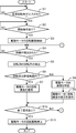
- FIG. 4 is a flowchart showing processing executed by the control device of FIG.
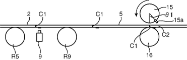
- FIG. 5 is a side view schematically showing the operation of the control device of FIG. 1, and shows a state where the cutting blade is at the reference rotation angle.
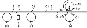
- FIG. 6 is a side view schematically showing the operation of the control device of FIG. 1 and shows a state in which the actual rotation angle of the cutting blade is advanced from the reference rotation angle.
- FIG. 7 is a side view schematically showing the operation of the control device of FIG. 1, and shows a state in which the actual rotation angle of the cutting blade is retracted from the reference rotation angle.
- FIG. 1 is a schematic view showing a configuration of a wearing article manufacturing apparatus according to an embodiment of the present invention.
- the manufacturing apparatus 1 is for manufacturing a disposable diaper having an absorbent core 4. Specifically, the manufacturing apparatus 1 includes a line L1 that conveys the back sheet 2, a line L2 that conveys the top sheet 3, a line L3 that conveys the absorbent core 4, and the back sheet 2 and the top sheet 3. It is roughly divided into a line L4 for conveying the joined body 5.
- the line L 1 includes a roll 6 around which the back sheet 2 is wound, guide rollers R 1 to R 3 for conveying the back sheet 2 fed from the roll 6 along a predetermined path, and a back sheet 2.
- a dancer roller R4 for applying tension to the roller, a driving roller R5 for applying power for pulling the back sheet 2 from the roll 6, and a roll motor for rotating the roll 6 (see FIG. 3).
- a drive motor for rotating the drive roller R5, an index detection sensor 9 capable of detecting an index provided on the backsheet 2, and tension by the dancer roller R4 are adjusted.
- a tension motor 10 is provided.
- an elastic member is attached to the back sheet 2 in an expanded state as necessary, or a fastening tape is attached.
- the back sheet 2 conveyed in the line L1 is a sheet (for example, a sheet made of a water-repellent nonwoven fabric or a plastic film) having a property of not allowing liquid to permeate.
- the back sheet 2 is provided with a plurality of indexes 2a at the same interval as the cutting position C1 of the back sheet 2 by a cutting device 14 described later.
- Each index 2a according to the present embodiment is composed of characters, figures, symbols or patterns printed on the backsheet 2.
- an article for example, a fastening tape
- the line L2 is provided with guide rollers R6 and R7 for conveying the top sheet 3 along a predetermined path.
- the top sheet 3 conveyed in the line L2 is a sheet having a property of transmitting liquid (for example, a sheet made of a liquid-permeable nonwoven fabric or a plastic film having an opening).
- the top sheet 3 is joined onto the back sheet 2 at a line L4 described later.
- the attachment device 12 has the longitudinal direction of the substantially rectangular absorbent core 4 along the longitudinal direction of the backsheet 2, and the absorbent core 4 is placed at the same interval as the cutting position C1. 2 is joined. That is, as shown in FIG. 2, the indicator 2 a is provided on the outer surface (the lower surface in FIG. 1) of the backsheet 2, and the absorbent core 4 is disposed on the inner surface (the upper surface in FIG. 1) of the backsheet 2. Will be provided.
- the conveying speed of the absorbent core 4 by the conveyor 11 is controlled by the line L1.
- the absorbent core 4 is arranged on the back sheet 2 at intervals by passing the absorbent core 4 from the conveyor 11 to the line L1 with a fixed period by the attachment device 12 after making it slower than the conveying speed of the sheet 2. can do.
- the mounting device 12 can be omitted, and the absorbent core 4 can be directly delivered from the conveyor 11 to the line L4 described later.
- the nip rolls R8 and R9 which will be described later, provided in the line L4 with a function of sucking and holding the absorbent core 4, the absorbent core 4 is transferred from the conveyor 11 to the back sheet by the nip rolls R8 and R9. 2 can be picked up.
- the nip rolls R8 and R9 constitute an attachment portion.
- the absorbent core 4 conveyed in the line L3 is a fluff pulp obtained by pulverizing pulp, and may contain a super absorbent polymer or the like.
- the line L4 includes a pair of nip rolls R8 and R9 for sandwiching the back sheet 2 and the top sheet 3, and a cutting device 14 for cutting the back sheet 2 and the top sheet 3 at the cutting position C1 (see FIG. 2). And are provided.
- the nip rolls R8 and R9 are arranged to face each other with the joined body 5 of the back sheet 2 and the top sheet 3 interposed therebetween, and each of the nip rolls R8 and R9 is guided to the downstream side by rotating.
- the cutting device 14 includes a rotary cutter 15 having a rotary blade 15 a, a counter roller 16 disposed to face the rotary cutter 15, and a motor (not shown) that rotationally drives the rotary cutter 15. ) And an angle detection sensor 17 (see FIG. 3) including a rotary encoder that detects the rotational position of the motor (that is, the rotational position of the rotary blade 15a).
- the rotary cutter 15 and the counter roller 16 are disposed with the joined body 5 of the back sheet 2 and the top sheet 3 interposed therebetween, and rotate in synchronization with each other, thereby transporting the joined body 5 by the rotary blade 15a.
- the joined body 5 is cut every rotation.
- FIG. 3 is a block diagram showing an electrical configuration of the control device 18 of FIG.
- control device 18 is electrically connected to the drive motor 8, the roll motor 7, the tension motor 10, the index detection sensor 9, and the angle detection sensor 17. Yes.
- the control device 18 is provided with an input unit 19 for an operator to input various settings.
- control device 18 includes a storage unit 20, a drive control unit 21, and an arithmetic processing unit 22.
- the storage unit 20 is used as an area for storing initial settings and the like, and can store information output from the input unit 19. Specifically, the storage unit 20 stores a reference rotation angle that is a rotation angle of the rotary blade 15a for cutting the joined body 5 of the back sheet 2 and the top sheet 3 at a preset cutting position C1.
- the reference rotation angle is the rotation angle of the rotary blade 15a of the rotary cutter 15 at the time when the index detection sensor 9 detects the index 2a of the backsheet 2. If the rotation angle is the reference rotation angle, the rotary blade 15 a is set in advance as reaching the cutting position C ⁇ b> 1 of the joined body 5.
- the storage unit 20 stores a scheduled period that is a period from when one index 2a (see FIG. 2) is detected by the index detection sensor 9 until the next index 2a is detected. This scheduled period is a period determined by the conveyance speed of the back sheet 2 and the interval between the indexes 2 a provided on the back sheet 2.
- the drive control unit 21 drives the drive motor 8, the roll motor 7 and the tension motor 10 based on the settings stored in the storage unit 20 or the settings determined by the arithmetic processing unit 22 described later.
- the drive control unit 21 receives the signal from the input unit 19 and drives the drive motor 8, the roll motor 7, and the tension motor 10.
- the arithmetic processing unit 22 calculates the reference rotation angle and the actual rotation angle of the rotary blade 15a based on the detection results of the index detection sensor 9 and the angle detection sensor 17 and the reference rotation angle stored in the storage unit 20. Detect the difference. Further, the arithmetic processing unit 22 calculates the speed of the drive motor 8 for filling the difference in the rotation angle during the scheduled period. The contents of the processing executed by the arithmetic processing unit 22 will be described with reference to FIGS.
- the state shown in FIG. 5 shows a state where the rotation angle of the rotary blade 15a is at the reference rotation angle (the rotation angle corresponding to the cutting position C1 of the joined body 5) when the index 2a is detected by the index detection sensor 9. ing.
- FIG. 6 shows the case where the rotation angle of the rotary blade 15a at the time when the index 2a is detected by the index detection sensor 9 is advanced by the angle ⁇ 1 from the reference rotation angle (at the cutting position C2 downstream of the cutting position C1). Shows the case of disconnection).
- the transport position of the joined body 5 is rotated by the rotary blade 15 a because the joined body 5 is stretched more than expected due to the fluctuation of the tension applied to the joined body 5. It is in a state of retreating relative to the position.
- the arithmetic processing unit 22 specifies the angle difference ⁇ 1 from the reference rotation angle, and with respect to the rotation angle of the rotary blade 15a from the present time to a scheduled period (a period until the next index 2a is detected).
- a command for causing the rotation angle of the drive motor 8 to relatively advance by the angle ⁇ 1 (command for increasing the speed of the drive motor 8) is output to the drive control unit 21.
- the relationship of the following formula (1) needs to be established.
- w1 is an angular velocity (rad / s) of the drive motor 8
- t is a scheduled period (s)
- r1 is a radius of the drive roller R5.
- W2 is the angular velocity of the rotary cutter 15, and r2 is the radius of the rotary cutter 15.
- W1 ⁇ ( ⁇ 1 ⁇ t ⁇ 2 ⁇ r2) + (w2 ⁇ t ⁇ 2 ⁇ r2) ⁇ ⁇ (t ⁇ 2 ⁇ r1) (2)
- FIG. 7 shows the case where the rotation angle of the rotary blade 15a at the time when the index 2a is detected by the index detection sensor 9 is retracted by the angle ⁇ 2 from the reference rotation angle (cutting position upstream of the cutting position C1). In the case of cutting at C3).
- the transport position of the joined body 5 is the rotation of the rotary blade 15a due to the fact that the joined body 5 is not expanded more than expected due to the fluctuation of the tension applied to the joined body 5. It is in a state of proceeding relative to the position.
- the arithmetic processing unit 22 identifies the angle difference ⁇ 2 from the reference rotation angle, and retreats the rotation angle of the drive motor 8 relative to the rotation angle of the rotary blade 15a relative to the rotation angle from the current time by the angle ⁇ 2.
- Command (command for decelerating the drive motor 8) is output to the drive control unit 21. Specifically, in order to change to the state of FIG. 5 after the lapse of the scheduled period from the state of FIG. 7, the relationship of the following formula (3) needs to be established.
- W1 ⁇ (w2 ⁇ t ⁇ 2 ⁇ r2)-( ⁇ 2 ⁇ t ⁇ 2 ⁇ r2) ⁇ ⁇ (t ⁇ 2 ⁇ r1) (4)
- a predetermined range can be set as the reference rotation angle. In other words, within this predetermined range, even when the reference rotation angle and the actual rotation angle do not match, the arithmetic processing unit 22 issues a command for maintaining the speed of the drive motor 8 constant. Output to the drive control unit 21.
- step S1 it waits whether or not a reference rotation angle has been input (step S1). That is, it is determined whether or not the reference rotation angle (rotation angle and its allowable range) is input by the input unit 19.
- step S1 If it is determined that the reference rotation angle has been input (YES in step S1), it is determined whether a start operation has been input by the input unit 19 (step S2), and if it has not been input (step S2). NO), step S2 is repeatedly executed.
- step S2 when a start operation is input (YES in step S2), rotation driving of the drive motor 8 and the rotary cutter 15 is started (step S3), and it is determined whether or not the index 2a is detected (step S4). ).
- step S4 is repeatedly executed. On the other hand, if it is determined that the index 2a is detected (YES in step S4), the rotation angle of the rotary blade 15a is determined. Is detected (step S5).
- step S6 it is determined whether or not the rotation angle of the rotary blade 15a is within the allowable range of the reference rotation angle. If it is determined that the rotation angle is within the allowable range (YES in step S6), the drive motor 8 The rotation speed is maintained (step S7).
- step S8 a speed change command is output to the drive motor 8 (step S9).
- step S7 and step S9 it is determined whether or not an end operation has been performed by the input unit 19 (step S10). If it is determined that the end operation has not been performed (NO in step S10), the step S4 is repeatedly executed.
- step S10 if it is determined in step S10 that the end operation has been performed, the driving of the drive motor 8 is stopped (step S11), and the process ends.
- the control device 18 controls the rotation speed of the drive motor 8 in a direction that reduces the difference between the reference rotation angle and the rotation angle detected by the angle detection sensor 17. Since the conveyance speed of the back sheet 2 with respect to the rotary blade 15a can be adjusted in an appropriate direction every time the index 2a is detected, the cutting position with respect to the index 2a can be set appropriately.
- the absorber can be manufactured with high accuracy.
- the position of the tape and the printing provided on the absorbent core 4 and the back sheet 2 are substantially uniform for each disposable diaper. Therefore, it can suppress that appearance and usability change for every disposable diaper.
- an angle range is set as a reference rotation angle (step S1), and when the rotation angle detected by the angle detection sensor 17 is within the angle range (YES in step S6), driving is performed. If the rotation speed of the motor 8 is kept constant (step S7), it is possible to simplify the control by setting a range in which the speed control of the drive motor 8 can be omitted.
- the difference in the rotation angle is set to the scheduled period. It becomes possible to fill in after the elapse of time.
- the reference rotation angle stored in the storage unit 20 can be input according to the type of disposable diaper and the characteristics of the sheet.
- the sheet conveyance speed control method corresponds to this cutting position when a sheet conveyed by the rotational drive of the drive roller is cut at a predetermined length by a cutting member having a rotary blade.
- the sheet conveyance speed is controlled such that the plurality of indexes provided on the sheet and the cutting position have a predetermined positional relationship, and upstream of the cutting member in the sheet conveyance direction.
- a setting step of setting a reference rotation angle as the rotation angle of the rotary blade for establishing the predetermined positional relationship when the index is detected at the detection position, and the drive roller and the cutting member are driven to rotate A driving step; a first detection step of detecting an index of the sheet at the detection position; and a rotary blade of the cutting member when the index is detected in the first detection step.
- a speed control step of controlling the rotational speed of the drive roller in the direction of moving
- the rotational speed of the driving roller can be controlled in a direction approaching the reference rotation angle set so that the sheet index and the cutting position have a predetermined positional relationship.
- the conveyance speed of the sheet with respect to the rotary blade can be adjusted in an appropriate direction every time, and the cutting position with respect to the index can be set appropriately.
- a worn article can be manufactured with high accuracy.
- an angle range is set as the reference rotation angle
- the rotation angle detected in the second detection step is included in the angle range. It is preferable that the rotational speed of the drive roller is kept constant regardless of the angle difference specified in the specifying step.
- control method it is possible to simplify the method by setting a range in which the drive roller speed control can be omitted. That is, in the control method, even when the positional relationship between the index and the cutting position is out of the target positional relationship, the control of the rotational speed of the drive roller can be omitted if it is within a predetermined range. it can.
- a method for manufacturing a worn article wherein a sheet conveyed by rotational driving of a driving roller is attached to the sheet by cutting the sheet with a predetermined length by a cutting member having a rotary blade.
- a method for manufacturing a wearing article having a constituent article wherein the sheet is provided on the sheet corresponding to a cutting position by the cutting member at a detection position upstream of the cutting member in the conveyance direction of the sheet.
- a setting step of setting a reference rotation angle that is a rotation angle of the rotary blade when the index is detected, and the index and the cutting position have a predetermined positional relationship, and a driving roller and a cutting member A driving step of rotationally driving, an attaching step of attaching the constituent article to the sheet between the driving roller and the cutting member in the conveying direction of the sheet, A first detection step of detecting an index of the sheet at the exit position; a second detection step of detecting a rotation angle of the rotary blade of the cutting member when the index is detected in the first detection step; (2) a specifying step for specifying a difference between the rotation angle detected in the detection step and the reference rotation angle, and a speed for controlling the rotation speed of the driving roller in a direction to reduce the angle difference specified in the specifying step. Control step.
- the rotational speed of the drive roller can be controlled in a direction approaching the reference rotation angle set so that the sheet index and the cutting position are in a predetermined positional relationship.
- the conveyance speed of the sheet with respect to the rotary blade can be adjusted in an appropriate direction every time, and the cutting position with respect to the index can be set appropriately.
- the manufacturing method since the sheet to which the constituent article is attached in the attachment process can be cut with high accuracy, the wearing article can be manufactured with high accuracy.
- an angle range is set as the reference rotation angle
- the rotation angle detected in the second detection step is included in the angle range. It is preferable that the rotational speed of the drive roller is kept constant regardless of the angle difference specified in the specifying step.
- the method can be simplified by setting a range in which the speed control of the driving roller can be omitted. That is, in the manufacturing method, even when the positional relationship between the index and the cutting position is out of the target positional relationship, the control of the rotational speed of the drive roller can be omitted if it is within a predetermined range. it can.
- the absorbent core as the constituent article is attached on the sheet, and after the attachment step, the absorbent core is sandwiched between the sheet and the sheet. It is preferable to further include a joining step for joining the second sheet.
- a wearing article in which an absorbent core is sandwiched between a pair of sheets can be manufactured.
- a wearing article manufacturing apparatus is a wearing article manufacturing apparatus having a sheet and a component article mounted on the sheet, and a driving roller capable of conveying the sheet;
- a drive motor that rotationally drives the drive roller; a mounting portion that allows the component to be mounted on the sheet; a cutting member having a rotary blade capable of cutting the sheet at predetermined intervals according to the rotational drive; and the drive
- a first detection member provided between the roller and the cutting member and capable of detecting an index provided on the sheet corresponding to a cutting position by the cutting member; and a first detection member capable of detecting a rotation angle of the cutting member. 2 based on the detection results of the two detection members and the first detection member and the second detection member, the rotational speed of the drive motor is controlled so that the index and the cutting position have a predetermined positional relationship.
- a device based on the detection results of the two detection members and the first detection member and the second detection member, the rotational speed of the drive motor is controlled so that the index and the cutting position have a predetermined positional
- the rotation angle of the drive roller is controlled so that the sheet index and the cutting position have a predetermined positional relationship
- the sheet conveyance speed with respect to the rotary blade is appropriate every time the index is detected. It is adjusted in the direction, and the cutting position for the index can be set appropriately.
- the manufacturing apparatus since the sheet to which the constituent article is attached can be cut with high accuracy, the wearing article can be manufactured with high accuracy.
- the control device is a rotation angle of the cutting member detected by the second detection member when the index is detected by the first detection member, and the index and the cutting position And a storage unit that stores a reference rotation angle that is set in advance so that the predetermined positional relationship is established, and a difference between the rotation angle of the cutting member detected by the second detection member and the reference rotation angle is specified It is preferable to include an arithmetic processing unit that performs the operation and a drive control unit that outputs a signal for changing the speed of the drive motor to the drive motor in a direction to reduce the difference in the rotation angle.
- the storage unit stores an angle range as the reference rotation angle
- the drive control unit includes a rotation angle detected by the second detection member in the angle range.
- the driving speed of the driving motor is maintained constant regardless of the angle difference specified by the arithmetic processing unit.
- this manufacturing apparatus it is possible to simplify the processing by the drive control unit by setting a range in which the speed control of the drive motor can be omitted. That is, in the manufacturing apparatus, even when the positional relationship between the index and the cutting position is out of the target positional relationship, the control of the rotational speed of the driving roller may be omitted if it is within a predetermined range. it can.
- the storage unit stores a scheduled period set in advance as a period from detection of one index to detection of the next index, and the arithmetic processing unit calculates the difference in the rotation angle. It is preferable to specify the rotational speed of the drive motor to fill during the scheduled period.
- the difference between the reference rotation angle and the actual rotation angle can be filled in until the next index is detected by setting the rotation speed specified by the arithmetic processing unit.
- the manufacturing apparatus further includes an input unit capable of inputting the reference rotation angle to the storage unit upon receiving a user operation.
- this manufacturing apparatus it is possible to input the reference rotation angle stored in the storage unit according to the type of wearing article, the characteristics of the sheet, and the like.
- a wearing article according to still another aspect of the present invention is manufactured by the manufacturing apparatus.
- this wearing article it is possible to provide a wearing article in which the positional relationship between the index (component article) and the cutting position is appropriately set.
- the present invention can be suitably used when manufacturing wearing articles such as disposable diapers and absorbent bodies.
Landscapes
- Health & Medical Sciences (AREA)
- Engineering & Computer Science (AREA)
- Life Sciences & Earth Sciences (AREA)
- Animal Behavior & Ethology (AREA)
- Public Health (AREA)
- Heart & Thoracic Surgery (AREA)
- Vascular Medicine (AREA)
- Epidemiology (AREA)
- Manufacturing & Machinery (AREA)
- General Health & Medical Sciences (AREA)
- Biomedical Technology (AREA)
- Veterinary Medicine (AREA)
- Mechanical Engineering (AREA)
- Forests & Forestry (AREA)
- Absorbent Articles And Supports Therefor (AREA)
- Controlling Rewinding, Feeding, Winding, Or Abnormalities Of Webs (AREA)
- Control Of Cutting Processes (AREA)
- Labeling Devices (AREA)
Abstract
Description
Claims (11)
- 駆動ローラの回転駆動により搬送されるシートを回転刃を有する切断部材により所定の長さで切断する際に、この切断位置に対応して前記シートに設けられた複数の指標と前記切断位置とが所定の位置関係となるように前記シートの搬送速度を制御する方法であって、
前記シートの搬送方向における前記切断部材よりも上流側の検出位置において前記指標が検出されたときに前記所定の位置関係が成立するための前記回転刃の回転角として、基準回転角を設定する設定工程と、
前記駆動ローラ及び切断部材を回転駆動させる駆動工程と、
前記検出位置において前記シートの指標を検出する第1検出工程と、
前記第1検出工程において前記指標が検出された時に、前記切断部材の回転刃の回転角を検出する第2検出工程と、
前記第2検出工程において検出された回転角と前記基準回転角との角度の差を特定する特定工程と、
前記特定工程において特定された角度差を小さくする方向に前記駆動ローラの回転速度を制御する速度制御工程とを含むことを特徴とするシートの搬送速度の制御方法。 - 前記設定工程では、前記基準回転角として角度範囲を設定し、
前記速度制御工程では、前記第2検出工程において検出された回転角が前記角度範囲に含まれている場合には、前記特定工程において特定された角度差にかかわらず前記駆動ローラの回転速度を一定に維持することを特徴とする請求項1に記載のシートの搬送速度の制御方法。 - 駆動ローラの回転駆動により搬送されるシートを回転刃を有する切断部材により所定の長さで切断することによって、前記シート上に取り付けられた構成物品を有する着用物品を製造するための方法であって、
前記シートの搬送方向における前記切断部材よりも上流側の検出位置において、前記切断部材による切断位置に対応して前記シートに設けられた指標が検出された時の前記回転刃の回転角であり、かつ、前記指標と前記切断位置とが所定の位置関係となるための基準回転角を設定する設定工程と、
駆動ローラ及び切断部材を回転駆動させる駆動工程と、
前記シートの搬送方向における前記駆動ローラと前記切断部材との間で前記シートに前記構成物品を取り付ける取付工程と、
前記検出位置において前記シートの指標を検出する第1検出工程と、
前記第1検出工程において前記指標が検出された時に、前記切断部材の回転刃の回転角を検出する第2検出工程と、
前記第2検出工程において検出された回転角と前記基準回転角との角度の差を特定する特定工程と、
前記特定工程において特定された角度差を小さくする方向に前記駆動ローラの回転速度を制御する速度制御工程とを含むことを特徴とする着用物品の製造方法。 - 前記設定工程では、前記基準回転角として角度範囲を設定し、
前記速度制御工程では、前記第2検出工程において検出された回転角が前記角度範囲に含まれている場合には、前記特定工程において特定された角度差にかかわらず前記駆動ローラの回転速度を一定に維持することを特徴とする請求項3に記載の着用物品の製造方法。 - 前記取付工程では、前記構成物品としての吸収性コアを前記シート上に取り付け、
前記取付工程の後に、前記吸収性コアを前記シートとの間で挟むように、前記シート上に第2シートを接合する接合工程をさらに備えていることを特徴とする請求項3又は4に記載の着用物品の製造方法。 - シートと、前記シート上に取り付けられた構成物品とを有する着用物品の製造装置であって、
前記シートを搬送可能な駆動ローラと、
前記駆動ローラを回転駆動させる駆動モータと、
前記シート上に前記構成物品を取付可能な取付部と、
回転駆動に応じて所定間隔で前記シートを切断可能な回転刃を有する切断部材と、
前記駆動ローラと前記切断部材との間に設けられ、前記切断部材による切断位置に対応して前記シートに設けられた指標を検出可能な第1検出部材と、
前記切断部材の回転角を検出可能な第2検出部材と、
前記第1検出部材及び第2検出部材の検出結果に基づいて、前記指標と前記切断位置とが所定の位置関係となるように、前記駆動モータの回転速度を制御する制御装置とを備えていることを特徴とする着用物品の製造装置。 - 前記制御装置は、
前記第1検出部材により前記指標が検出された時点における前記第2検出部材により検出される前記切断部材の回転角であり、かつ、前記指標と前記切断位置とが前記所定の位置関係となるように予め設定された基準回転角を記憶する記憶部と、
前記第2検出部材により検出された前記切断部材の回転角と前記基準回転角との差を特定する演算処理部と、
前記回転角の差を小さくする方向に前記駆動モータの速度を変化させるための信号を前記駆動モータに出力する駆動制御部と、
を備えていることを特徴とする請求項6に記載の着用物品の製造装置。 - 前記記憶部は、前記基準回転角として角度範囲を記憶しており、
前記駆動制御部は、前記第2検出部材により検出された回転角が前記角度範囲に含まれている場合には、前記演算処理部により特定された角度差にかかわらず前記駆動モータの駆動速度を一定に維持することを特徴とする請求項7に記載の着用物品の製造装置。 - 前記記憶部は、1の指標の検知から次の指標の検知までの期間として予め設定された予定期間を記憶しており、
前記演算処理部は、前記回転角の差を前記予定期間の間に埋めるための駆動モータの回転速度を特定することを特徴とする請求項7又は8に記載の着用物品の製造装置。 - 使用者の操作を受けることにより前記記憶部に前記基準回転角を入力可能な入力部をさらに備えていることを特徴とする請求項7~9の何れか1項に記載の着用物品の製造装置。
- 請求項6~10の何れか1項に記載の製造装置により製造されたことを特徴とする着用物品。
Priority Applications (5)
| Application Number | Priority Date | Filing Date | Title |
|---|---|---|---|
| JP2011519418A JP5631876B2 (ja) | 2009-06-23 | 2009-06-23 | シートの搬送速度制御方法、着用物品の製造方法、及び着用物品の製造装置 |
| CN200980160065.XA CN102802573B (zh) | 2009-06-23 | 2009-06-23 | 片材的搬送速度控制方法、穿用物品的制造方法、穿用物品的制造装置以及穿用物品 |
| DE112009004995.8T DE112009004995B4 (de) | 2009-06-23 | 2009-06-23 | Verfahren zum Herstellen eines Hygieneartikels zum Tragen, Einrichtung zum Herstellen eines Hygieneartikels zum Tragen |
| US13/378,468 US9073230B2 (en) | 2009-06-23 | 2009-06-23 | Method for controlling conveyance speed of sheet, method for manufacturing wearing article, apparatus for manufacturing wearing article, and wearing article |
| PCT/JP2009/061414 WO2010150357A1 (ja) | 2009-06-23 | 2009-06-23 | シートの搬送速度制御方法、着用物品の製造方法、着用物品の製造装置、及び着用物品 |
Applications Claiming Priority (1)
| Application Number | Priority Date | Filing Date | Title |
|---|---|---|---|
| PCT/JP2009/061414 WO2010150357A1 (ja) | 2009-06-23 | 2009-06-23 | シートの搬送速度制御方法、着用物品の製造方法、着用物品の製造装置、及び着用物品 |
Publications (1)
| Publication Number | Publication Date |
|---|---|
| WO2010150357A1 true WO2010150357A1 (ja) | 2010-12-29 |
Family
ID=43386152
Family Applications (1)
| Application Number | Title | Priority Date | Filing Date |
|---|---|---|---|
| PCT/JP2009/061414 Ceased WO2010150357A1 (ja) | 2009-06-23 | 2009-06-23 | シートの搬送速度制御方法、着用物品の製造方法、着用物品の製造装置、及び着用物品 |
Country Status (5)
| Country | Link |
|---|---|
| US (1) | US9073230B2 (ja) |
| JP (1) | JP5631876B2 (ja) |
| CN (1) | CN102802573B (ja) |
| DE (1) | DE112009004995B4 (ja) |
| WO (1) | WO2010150357A1 (ja) |
Cited By (3)
| Publication number | Priority date | Publication date | Assignee | Title |
|---|---|---|---|---|
| JP2015006702A (ja) * | 2013-06-24 | 2015-01-15 | 株式会社ユウコス | ロータリーダイカッターシステム |
| JP2016182158A (ja) * | 2015-03-25 | 2016-10-20 | 新興機械株式会社 | 使い捨て着用物品、その製造装置及び製造方法 |
| JP2018149065A (ja) * | 2017-03-13 | 2018-09-27 | 王子ホールディングス株式会社 | 吸収性物品の製造装置に用いられる張力調整装置および張力調整方法 |
Families Citing this family (20)
| Publication number | Priority date | Publication date | Assignee | Title |
|---|---|---|---|---|
| US8505423B2 (en) | 2009-01-08 | 2013-08-13 | Esys Corporation | Weight material dispensing and cutting system |
| US20130269493A1 (en) * | 2012-04-17 | 2013-10-17 | Goss International Americas, Inc. | Variable cutoff in a cutter folder |
| JP5801843B2 (ja) * | 2013-04-25 | 2015-10-28 | 株式会社ブリヂストン | 耳片の突出量測定方法及び耳片の突出量測定装置 |
| JP5786056B1 (ja) * | 2014-03-27 | 2015-09-30 | ユニ・チャーム株式会社 | 吸収性物品の製造装置、及び吸収性物品の製造方法 |
| JP5760110B1 (ja) | 2014-03-27 | 2015-08-05 | ユニ・チャーム株式会社 | 吸収性物品に係る複合シートの製造装置、及び製造方法 |
| AU2014396902B2 (en) * | 2014-06-13 | 2017-01-19 | Essity Hygiene And Health Aktiebolag | A packaging unit for hygiene articles and a method of forming a packaging unit |
| US9834355B2 (en) | 2014-06-13 | 2017-12-05 | Sca Hygiene Products Ab | Packaging unit having improved sealing, and a method for forming such a packaging unit |
| US10086989B2 (en) | 2014-06-13 | 2018-10-02 | Sca Hygiene Products Ab | Packaging unit for hygiene articles and a method of forming a packaging unit |
| CN106456418A (zh) | 2014-06-13 | 2017-02-22 | Sca卫生用品公司 | 具有改良密封性和使用者提示装置的包装单元及用于制造此包装单元的方法 |
| BR112016028062B1 (pt) | 2014-06-13 | 2021-12-14 | Essity Hygiene And Health Aktiebolag | Unidade de empacotamento para artigos de higiene e método de formação de uma unidade de empacotamento para artigos de higiene |
| RU2644113C1 (ru) | 2014-06-13 | 2018-02-07 | Ска Хайджин Продактс Аб | Способ образования обертывающего листа, имеющего улучшенную герметизирующую способность |
| JP5895106B1 (ja) * | 2015-06-29 | 2016-03-30 | ユニ・チャーム株式会社 | シート固定方法、及び、シート固定装置 |
| CN107613919B (zh) * | 2015-06-29 | 2019-02-15 | 尤妮佳股份有限公司 | 片材固定方法以及片材固定装置 |
| CN105726217B (zh) * | 2016-01-29 | 2019-03-01 | 泉州市汉威机械制造有限公司 | 一种高分子间断施加控制方法 |
| CN108882995B (zh) * | 2016-03-28 | 2019-12-13 | 尤妮佳股份有限公司 | 用于制造吸收性物品的包装体的方法和设备 |
| EP3441052B1 (en) * | 2016-04-08 | 2020-07-08 | Unicharm Corporation | Manufacturing method and manufacturing device for sheet-like member for absorbent article |
| JP7085324B2 (ja) * | 2017-08-30 | 2022-06-16 | ユニ・チャーム株式会社 | 包装体製造方法、及び、包装体製造装置 |
| US11273570B2 (en) * | 2018-05-25 | 2022-03-15 | Mespack Cloud, Llc | Pouch registration monitoring and control system |
| CN108855767B (zh) * | 2018-09-06 | 2019-12-03 | 武汉华茂自动化股份有限公司 | 定点涂布机的控制方法及定点涂布机 |
| JP7096200B2 (ja) * | 2019-05-20 | 2022-07-05 | ユニ・チャーム株式会社 | ペット用おむつ、ペット用おむつの収容体及びペット用おむつの製造方法 |
Citations (4)
| Publication number | Priority date | Publication date | Assignee | Title |
|---|---|---|---|---|
| JPH04314443A (ja) * | 1990-11-15 | 1992-11-05 | Paper Converting Mach Co Inc | おむつ製造装置の切断位置調整方法及びその装置 |
| JPH11502738A (ja) * | 1995-03-27 | 1999-03-09 | ザ、プロクター、エンド、ギャンブル、カンパニー | おむつ位置決め制御システム |
| JP2001029385A (ja) * | 1999-07-19 | 2001-02-06 | Kao Corp | 吸収性物品の製造方法 |
| JP2005080827A (ja) * | 2003-09-08 | 2005-03-31 | Oji Paper Co Ltd | 吸収性物品の製造方法 |
Family Cites Families (7)
| Publication number | Priority date | Publication date | Assignee | Title |
|---|---|---|---|---|
| WO1992005959A1 (en) * | 1990-09-27 | 1992-04-16 | Computype, Inc. | Rotary die cutting mechanism |
| AU712443B2 (en) | 1995-12-29 | 1999-11-04 | Kimberly-Clark Worldwide, Inc. | Disposable absorbent article having a registered graphic and process for making |
| US5818719A (en) | 1995-12-29 | 1998-10-06 | Kimberly-Clark, Worldwide, Inc. | Apparatus for controlling the registration of two continuously moving layers of material |
| US6092002A (en) | 1996-11-13 | 2000-07-18 | Kimberly-Clark Worldwide, Inc. | Variable tension process and apparatus for continuously moving layers |
| DE69818005T2 (de) | 1998-03-19 | 2004-06-24 | Fameccanica Data S.P.A. | Vorrichtung zum Schneiden bestimmter Längen von blattförmigen Elementen, insbesondere zum Herstellen von Sanitärprodukten |
| EP1162162B1 (en) | 1999-12-16 | 2006-11-22 | Zuiko Corporation | Method and device for transportation |
| US6895649B2 (en) | 2001-08-29 | 2005-05-24 | Zuiko Corporation | Article production method |
-
2009
- 2009-06-23 DE DE112009004995.8T patent/DE112009004995B4/de active Active
- 2009-06-23 WO PCT/JP2009/061414 patent/WO2010150357A1/ja not_active Ceased
- 2009-06-23 US US13/378,468 patent/US9073230B2/en active Active
- 2009-06-23 JP JP2011519418A patent/JP5631876B2/ja not_active Expired - Fee Related
- 2009-06-23 CN CN200980160065.XA patent/CN102802573B/zh active Active
Patent Citations (4)
| Publication number | Priority date | Publication date | Assignee | Title |
|---|---|---|---|---|
| JPH04314443A (ja) * | 1990-11-15 | 1992-11-05 | Paper Converting Mach Co Inc | おむつ製造装置の切断位置調整方法及びその装置 |
| JPH11502738A (ja) * | 1995-03-27 | 1999-03-09 | ザ、プロクター、エンド、ギャンブル、カンパニー | おむつ位置決め制御システム |
| JP2001029385A (ja) * | 1999-07-19 | 2001-02-06 | Kao Corp | 吸収性物品の製造方法 |
| JP2005080827A (ja) * | 2003-09-08 | 2005-03-31 | Oji Paper Co Ltd | 吸収性物品の製造方法 |
Cited By (4)
| Publication number | Priority date | Publication date | Assignee | Title |
|---|---|---|---|---|
| JP2015006702A (ja) * | 2013-06-24 | 2015-01-15 | 株式会社ユウコス | ロータリーダイカッターシステム |
| JP2016182158A (ja) * | 2015-03-25 | 2016-10-20 | 新興機械株式会社 | 使い捨て着用物品、その製造装置及び製造方法 |
| JP2018149065A (ja) * | 2017-03-13 | 2018-09-27 | 王子ホールディングス株式会社 | 吸収性物品の製造装置に用いられる張力調整装置および張力調整方法 |
| JP7115820B2 (ja) | 2017-03-13 | 2022-08-09 | 王子ホールディングス株式会社 | 吸収性物品の製造装置に用いられる張力調整装置および張力調整方法 |
Also Published As
| Publication number | Publication date |
|---|---|
| DE112009004995B4 (de) | 2023-08-17 |
| US9073230B2 (en) | 2015-07-07 |
| CN102802573A (zh) | 2012-11-28 |
| DE112009004995T5 (de) | 2012-10-25 |
| CN102802573B (zh) | 2016-06-01 |
| JPWO2010150357A1 (ja) | 2012-12-06 |
| JP5631876B2 (ja) | 2014-11-26 |
| US20120090071A1 (en) | 2012-04-19 |
Similar Documents
| Publication | Publication Date | Title |
|---|---|---|
| JP5631876B2 (ja) | シートの搬送速度制御方法、着用物品の製造方法、及び着用物品の製造装置 | |
| JP5155837B2 (ja) | シートの折り返し装置並びに該装置を用いた吸収性物品の製造方法及び吸収性物品 | |
| WO2001005345A1 (en) | Production method for absorbent article | |
| CN102482042B (zh) | 用于连续递送纤维网材料的体系和方法 | |
| JP2023514858A (ja) | 個々のスプールから巻き出された弾性ストランドを有するエラストマー積層体を作製するための方法及び装置 | |
| US20050241774A1 (en) | Apparatus and process for aligning materials during a splice | |
| EP2811957B1 (en) | Apparatuses for folding absorbent articles | |
| ITUB20150807A1 (it) | Dispositivo e metodo per realizzare saldature con ultrasuoni su materiali in nastro in movimento continuo | |
| JP7085324B2 (ja) | 包装体製造方法、及び、包装体製造装置 | |
| JP2005080827A (ja) | 吸収性物品の製造方法 | |
| US20160030252A1 (en) | Slip-Cut Operation with Static Electric Holding Force and Ultrasonic Bonding Apparatus | |
| EP3395309A1 (en) | Manufacturing method and manufacturing device for continuous sheet composite body pertaining to absorbent articles | |
| BR112013014922B1 (pt) | aplicador de fita configurado para guiar a fita para uma trama, e, aparelho para ligar a fita em um padrão não linear a uma trama | |
| CN108882995B (zh) | 用于制造吸收性物品的包装体的方法和设备 | |
| EP3424853B1 (en) | Material splicing method, and material supply device | |
| TWI556800B (zh) | Apparatus for manufacturing absorbent articles | |
| EP3741718B1 (en) | Absorbent article manufacturing method and absorbent article manufacturing device | |
| EP3157851B1 (en) | Apparatus and method for controlling the unwinding of a web | |
| JP2017202889A (ja) | ウェブガイド装置 | |
| JP6681515B2 (ja) | 第一のウェブを非線形パターンでベースウェブに貼るための装置および方法 | |
| WO2017221385A1 (ja) | 吸収性物品に係るシート状部材の製造方法及び製造装置 | |
| JP6008703B2 (ja) | 伸縮性複合シートの製造装置および製造方法 | |
| JP2003047630A (ja) | 吸収性物品用の長尺状連続部材 |
Legal Events
| Date | Code | Title | Description |
|---|---|---|---|
| WWE | Wipo information: entry into national phase |
Ref document number: 200980160065.X Country of ref document: CN |
|
| 121 | Ep: the epo has been informed by wipo that ep was designated in this application |
Ref document number: 09846490 Country of ref document: EP Kind code of ref document: A1 |
|
| WWE | Wipo information: entry into national phase |
Ref document number: 13378468 Country of ref document: US |
|
| WWE | Wipo information: entry into national phase |
Ref document number: 2011519418 Country of ref document: JP |
|
| WWE | Wipo information: entry into national phase |
Ref document number: 112009004995 Country of ref document: DE Ref document number: 1120090049958 Country of ref document: DE |
|
| 122 | Ep: pct application non-entry in european phase |
Ref document number: 09846490 Country of ref document: EP Kind code of ref document: A1 |