WO2010147170A1 - 熱交換器のろう付方法 - Google Patents
熱交換器のろう付方法 Download PDFInfo
- Publication number
- WO2010147170A1 WO2010147170A1 PCT/JP2010/060264 JP2010060264W WO2010147170A1 WO 2010147170 A1 WO2010147170 A1 WO 2010147170A1 JP 2010060264 W JP2010060264 W JP 2010060264W WO 2010147170 A1 WO2010147170 A1 WO 2010147170A1
- Authority
- WO
- WIPO (PCT)
- Prior art keywords
- brazing
- flux
- refrigerant chamber
- heat exchanger
- refrigerant
- Prior art date
- Legal status (The legal status is an assumption and is not a legal conclusion. Google has not performed a legal analysis and makes no representation as to the accuracy of the status listed.)
- Ceased
Links
Images

Classifications
-
- B—PERFORMING OPERATIONS; TRANSPORTING
- B23—MACHINE TOOLS; METAL-WORKING NOT OTHERWISE PROVIDED FOR
- B23K—SOLDERING OR UNSOLDERING; WELDING; CLADDING OR PLATING BY SOLDERING OR WELDING; CUTTING BY APPLYING HEAT LOCALLY, e.g. FLAME CUTTING; WORKING BY LASER BEAM
- B23K1/00—Soldering, e.g. brazing, or unsoldering
- B23K1/0008—Soldering, e.g. brazing, or unsoldering specially adapted for particular articles or work
- B23K1/0012—Brazing of heat exchangers
-
- B—PERFORMING OPERATIONS; TRANSPORTING
- B23—MACHINE TOOLS; METAL-WORKING NOT OTHERWISE PROVIDED FOR
- B23K—SOLDERING OR UNSOLDERING; WELDING; CLADDING OR PLATING BY SOLDERING OR WELDING; CUTTING BY APPLYING HEAT LOCALLY, e.g. FLAME CUTTING; WORKING BY LASER BEAM
- B23K1/00—Soldering, e.g. brazing, or unsoldering
- B23K1/008—Soldering within a furnace
-
- B—PERFORMING OPERATIONS; TRANSPORTING
- B23—MACHINE TOOLS; METAL-WORKING NOT OTHERWISE PROVIDED FOR
- B23K—SOLDERING OR UNSOLDERING; WELDING; CLADDING OR PLATING BY SOLDERING OR WELDING; CUTTING BY APPLYING HEAT LOCALLY, e.g. FLAME CUTTING; WORKING BY LASER BEAM
- B23K1/00—Soldering, e.g. brazing, or unsoldering
- B23K1/19—Soldering, e.g. brazing, or unsoldering taking account of the properties of the materials to be soldered
-
- B—PERFORMING OPERATIONS; TRANSPORTING
- B23—MACHINE TOOLS; METAL-WORKING NOT OTHERWISE PROVIDED FOR
- B23K—SOLDERING OR UNSOLDERING; WELDING; CLADDING OR PLATING BY SOLDERING OR WELDING; CUTTING BY APPLYING HEAT LOCALLY, e.g. FLAME CUTTING; WORKING BY LASER BEAM
- B23K1/00—Soldering, e.g. brazing, or unsoldering
- B23K1/20—Preliminary treatment of work or areas to be soldered, e.g. in respect of a galvanic coating
- B23K1/203—Fluxing, i.e. applying flux onto surfaces
-
- F—MECHANICAL ENGINEERING; LIGHTING; HEATING; WEAPONS; BLASTING
- F28—HEAT EXCHANGE IN GENERAL
- F28F—DETAILS OF HEAT-EXCHANGE AND HEAT-TRANSFER APPARATUS, OF GENERAL APPLICATION
- F28F21/00—Constructions of heat-exchange apparatus characterised by the selection of particular materials
- F28F21/08—Constructions of heat-exchange apparatus characterised by the selection of particular materials of metal
- F28F21/089—Coatings, claddings or bonding layers made from metals or metal alloys
-
- F—MECHANICAL ENGINEERING; LIGHTING; HEATING; WEAPONS; BLASTING
- F28—HEAT EXCHANGE IN GENERAL
- F28F—DETAILS OF HEAT-EXCHANGE AND HEAT-TRANSFER APPARATUS, OF GENERAL APPLICATION
- F28F3/00—Plate-like or laminated elements; Assemblies of plate-like or laminated elements
- F28F3/02—Elements or assemblies thereof with means for increasing heat-transfer area, e.g. with fins, with recesses, with corrugations
- F28F3/025—Elements or assemblies thereof with means for increasing heat-transfer area, e.g. with fins, with recesses, with corrugations the means being corrugated, plate-like elements
-
- F—MECHANICAL ENGINEERING; LIGHTING; HEATING; WEAPONS; BLASTING
- F28—HEAT EXCHANGE IN GENERAL
- F28F—DETAILS OF HEAT-EXCHANGE AND HEAT-TRANSFER APPARATUS, OF GENERAL APPLICATION
- F28F3/00—Plate-like or laminated elements; Assemblies of plate-like or laminated elements
- F28F3/12—Elements constructed in the shape of a hollow panel, e.g. with channels
-
- B—PERFORMING OPERATIONS; TRANSPORTING
- B23—MACHINE TOOLS; METAL-WORKING NOT OTHERWISE PROVIDED FOR
- B23K—SOLDERING OR UNSOLDERING; WELDING; CLADDING OR PLATING BY SOLDERING OR WELDING; CUTTING BY APPLYING HEAT LOCALLY, e.g. FLAME CUTTING; WORKING BY LASER BEAM
- B23K2101/00—Articles made by soldering, welding or cutting
- B23K2101/04—Tubular or hollow articles
- B23K2101/10—Pipe-lines
-
- B—PERFORMING OPERATIONS; TRANSPORTING
- B23—MACHINE TOOLS; METAL-WORKING NOT OTHERWISE PROVIDED FOR
- B23K—SOLDERING OR UNSOLDERING; WELDING; CLADDING OR PLATING BY SOLDERING OR WELDING; CUTTING BY APPLYING HEAT LOCALLY, e.g. FLAME CUTTING; WORKING BY LASER BEAM
- B23K2101/00—Articles made by soldering, welding or cutting
- B23K2101/04—Tubular or hollow articles
- B23K2101/14—Heat exchangers
Definitions
- the present invention relates to a brazing method for a heat exchanger having a semi-enclosed refrigerant chamber.
- Non-Patent Document 1 It is known that brazing of an aluminum material can be satisfactorily brazed without using a flux in an inert gas atmosphere (see Non-Patent Document 1).
- the present invention provides a brazed product or brazing environment by dropping off a flux while performing good brazing by attaching a flux to a refrigerant chamber in brazing of a semi-enclosed heat exchanger.
- the goal is to minimize contamination.
- the present invention has the configurations described in [1] to [7] below.
- At least one of the two members has a bulging portion, and this one member is arranged opposite to the other member in a state where fins are arranged in the bulging portion, and around the bulging portion.
- a heat exchanger brazing method in which a semi-sealed refrigerant chamber having a refrigerant inlet / outlet opening portion is formed by brazing to the other member, and fins are brazed into the refrigerant chamber, Fluoride-based flux particles are injected into at least a part of the part forming the refrigerant chamber and at least a part of the brazing part around the refrigerant chamber on both sides or one side of the opposing surfaces of the two members to collide at high speed Mechanically attach the flux particles, Assembling the two members and the fins into a temporary assembly in which the fins are arranged in the refrigerant chamber, A brazing method for a heat exchanger, wherein the temporary assembly is brazed by heating in an inert gas atmosphere.
- the inside of the refrigerant chamber is sufficiently replaced with an inert gas that is a brazing atmosphere. Even if the brazing material melts in a state where the brazing portion around the refrigerant chamber is not in contact with the inert gas, the inner surface of the refrigerant chamber and the fin are brazed well due to the effect of the flux.
- the brazing part around the refrigerant chamber is also brazed well.
- the flux When the flux is vaporized by brazing heat, the flux is also supplied to the non-adhered part to suppress the growth of the oxide film, and the vaporized flux reacts with oxygen and moisture in the atmosphere to improve the brazing atmosphere. . For this reason, even if the part which the flux has not adhered exists, the whole refrigerant chamber is brazed well.
- flux particles are jetted and collided at a high speed to the required part of the member to attach the flux particles mechanically, so even a small amount of flux can be uniformly attached, and good brazing can be achieved with a small amount of flux. Can be achieved.
- the adhesion method in which the flux particles collide with each other at such a high speed has a strong adhesion force of the flux, so that there is little dropout, and contamination of the brazed product and the brazing environment due to the dropped flux can be suppressed.
- the fins are satisfactorily brazed by the flux effect.
- the region near the opening is replaced with the inert gas at an early stage, the fins can be brazed well even without flux.
- the flux is vaporized by brazing additional heat, the flux is also supplied to the non-adhered part to suppress the growth of the oxide film, and the vaporized flux reacts with oxygen and moisture in the atmosphere to improve the brazing atmosphere. Therefore, by preferentially attaching the flux to a region far from the opening, the brazing property of the entire refrigerant chamber can be improved with a smaller amount of flux.
- the amount of flux attached is appropriate for achieving good brazing properties.
- the flux particles can be attached efficiently.
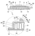
- FIG. 2 is a sectional view taken along line BB in FIG. It is typical explanatory drawing explaining the adhesion area
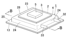
- FIG. 1 shows a state where an insulating substrate (3) for mounting a heating element (5) is brazed to a heat exchanger (1) brazed according to the present invention.
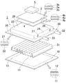
- 2 is an exploded perspective view of FIG. 1
- FIG. 3 is a sectional view taken along line BB of FIG.
- the heating element (5) is an electronic element such as an LED, IGBT, or semiconductor, and the heat exchanger (1) is used to cool them.
- the heat exchanger (1) includes a first member (10), a second member (20), a fin (31), an inlet pipe (32), and an outlet pipe (33).
- the three members of the first member (10), the second member (20) and the fin (31) are temporarily assembled and brazed together, and the inlet joint (32) and the outlet joint (33) Separately welded after brazing.
- the first member (10) is a rectangular flat plate, and is composed of a single-side brazing sheet in which a brazing material (12) is clad on one side of an aluminum core material (11).
- the peripheral region constitutes a joint portion (13) for brazing with the second member (20), and the central region forms a bottom wall (14) of the refrigerant chamber (2).
- the imaginary line on the upper surface of the first member (10) indicates the boundary between the joint portion (13) and the bottom wall (14).
- the second member (20) has the same planar dimension as the first member (10), and has a bulging portion (23) having a rectangular shape in plan view for forming the refrigerant chamber (2) at the center. Yes.
- the opening side periphery of the bulging portion (23) is bent outward from the side wall (24) to form a joint portion (25) for brazing to the first member (10).
- two circular holes (26) and (27) are formed in one side wall (24) of the bulging portion (23).
- This second member (20) was formed by pressing a required portion of a single-sided brazing sheet in which a brazing material (22) was clad on one side of an aluminum core material (21) to form a bulging portion (23).
- Circular holes (26) and (27) are formed in the side wall (24) of the bulging portion (23).
- the fin (31) is formed by corrugating aluminum bare material.
- the inlet joint (32) and the outlet joint (33) are round pipes corresponding to the circular holes (26) and (27) of the second member (20).
- the fins (31) are arranged inside the bulging portion (23) of the second member (20), and the first member (10) and the second member (20) are faced to the respective brazing materials (12) (22).
- the joints (13) and (25) are overlapped with each other facing inside, the bulging part (23) is closed by the first member (10) and only the circular holes (26) and (27) are opened.
- a semi-enclosed refrigerant chamber (2) is formed.
- the insulating substrate (3) is assembled to the temporary assembly of the heat exchanger (1), and the insulating substrate (3) is brazed simultaneously with the brazing of the heat exchanger (1).
- the insulating substrate (3) is a three-layer clad in which a heat conductive layer (3b) made of a material having high heat conductivity such as pure aluminum is laminated on both surfaces of an insulating layer (3a) made of aluminum oxide (Al 2 O 3 ) or the like. It is a material.
- a double-sided brazing sheet (4) in which a brazing material layer (4b) (4b) is clad on both sides of a core material (4a) is used.
- the brazing is performed on the outer surface of the refrigerant chamber (2) of the temporary assembly of the heat exchanger (1), that is, the ceiling wall (23) of the bulging portion (23) of the second member (20).
- the brazing sheet (4) and the insulating substrate (3) are stacked on the outer surface of 28).
- the locations to be brazed are the joints (13) and (25) around the refrigerant chamber (2), the tops of the fins (31) and the ceiling of the bulge (23).
- the brazing heat is performed in an inert gas atmosphere.
- the outer surface of the bulging part (23), the insulating substrate (3), and the brazing sheet (4) are exposed, so that replacement with inert gas can be performed quickly.
- the inside of the refrigerant chamber (2) is replaced with inert gas through two small circular holes (26) and (27), it takes time until the internal atmosphere is replaced with inert gas. There is a situation. Further, the joint portions (13) and (25) are in contact with the inert gas on the outer peripheral side, but the inner peripheral side facing the refrigerant chamber (2) is a portion that is difficult to contact with the inert gas.
- brazing filler metal melts in a state where replacement with the inert gas in the refrigerant chamber (2) is insufficient, the refrigerant in the inner surface of the refrigerant chamber (2) and the fins (31) or the joints (13) (25) The part facing the chamber (2) is poorly brazed.
- the present invention for the inner part of the refrigerant chamber (2), which takes time to replace with the inert gas, and the joint portion (13) (25) which is difficult to contact with the inert gas, a method specific to the member before temporary assembly In this case, the flux is applied, and even when the brazing temperature is reached with the air remaining, good brazing can be surely achieved by the effect of the flux. On the other hand, since the exposed brazing location is quickly replaced with an inert gas, good brazing can be achieved without applying flux. As described above, by selectively applying the flux to the portion that is difficult to be replaced by the inert gas, it is possible to achieve good brazing while reducing the amount of flux used.
- the application of the flux is performed by spraying the flux particles to a required portion of the member at a low temperature, causing the flux particles to collide at high speed, and mechanically adhering to the surface.
- the mechanical adhesion is a state in which the flux particles are directly adhered to the member without using a binder.
- such a flux adhesion method is abbreviated as cold spray.
- flux particles are sprayed at high speed from a nozzle of an spraying device by a carrier gas, and particles such as flux collide and adhere to the surface of a member.
- the flux particles colliding with the member are mechanically attached in a state of being deformed flat by impact, and a uniform flux adhesion layer is formed even with a small amount of adhesion.
- the particles in the spray material have a spherical shape or a shape closer to the spherical shape than the adhered particles. However, by deforming and adhering to a flat shape, it is possible to cover a larger area than when adhering in a spherical shape.
- the flux can be uniformly supplied to the brazed portion.
- the flux particles have a strong adhesive force and the amount of dropout is less than that applied and applied with the flux liquid, the brazing environment is less contaminated by the dropout flux.
- the flux can be attached to a desired portion by relatively moving the member and the nozzle of the injection device.
- non-corrosive fluoride flux As the type of flux, non-corrosive fluoride flux is used. Specifically AlF 3, KF, KAlF 4, K 2 AlF 5, K 3 AlF 6, ZnF 2, KZnF 3, LiF, can be exemplified BiF 3, CsF. These fluxes can be used alone or as a mixture of two or more.
- the flux does not necessarily have to be attached to the entire area of the portion forming the inner surface of the refrigerant chamber (2) and the joint portion (13) (25), and at least a part of the portion forming the inner surface of the refrigerant chamber (2) and What is necessary is just to make it adhere to at least one part of a joint part (13) (25).
- the flux is vaporized by the brazing heat, the flux is also supplied to the non-adhered portion to suppress the growth of the oxide film.
- the vaporized flux has an effect of improving the brazing atmosphere by reacting with oxygen and moisture in the atmosphere. Accordingly, the present invention includes a case where the flux is attached to only one member of the two members (10) and (20), and a case where the flux is attached to a part of one member.
- the outer peripheral side of the joints (13) and (25) around the refrigerant chamber (2) is in contact with the inert gas, but the inner peripheral side facing the refrigerant chamber (2) is in the refrigerant chamber (2).
- the flux is attached to at least a part of the part forming the refrigerant chamber and at least a part of the brazing part around the refrigerant chamber on both sides or one side of the opposing surfaces of the two members. It becomes a condition.
- the flux When the flux is partially adhered on the inner surface of the refrigerant chamber (2), it is preferably adhered to a portion far from the circular holes (26) and (27). This is because the circular holes (26) and (27), that is, the portions close to the opening of the refrigerant chamber (2) are replaced with the inert gas at an early stage, so that good brazing can be achieved without flux. .
- the flux adhering to the vicinity of the opening is likely to escape from the opening to the refrigerant chamber (2) at an early stage, and contributes little to the brazing property improvement effect in the refrigerant chamber (2). . Therefore, in order to improve the brazing property in the refrigerant chamber (2) with a smaller amount of flux, it is preferable to preferentially adhere the flux to a region far from the opening.
- FIG. 4 is a schematic plan view of the heat exchanger (1) of the present embodiment. Since the heat exchanger (1) is provided with circular holes (26) and (27) only in one side wall (24) of the refrigerant chamber (2), the area indicated by the halftone dots is an area (A1) far from the opening. ), And the shaded area is the area (A2) close to the opening. As described above, when the flux is partially attached, it is preferable that (A1) far from the opening is an attached region and (A2) near the opening is an unattached region.
- the area of the adhering area (A1) should be set within a range of 10 to 50% of the total area of the inner surface of the refrigerant chamber (2) and the joints (13) and (25) around the refrigerant chamber (2). Is preferred.
- the joint portion (13) and bottom wall (14) of the first member (10), the ceiling wall (28) of the bulging portion (23) of the second member (20) and the four side walls (24) (circular holes) And the joint (25) is preferably set in the range of 10 to 50% of the total area. If the area ratio of the adhesion region (A1) is less than 10%, the flux amount may be insufficient, and if it exceeds 50%, the reduction amount of the flux amount decreases. Therefore, the area ratio is in a range where good brazing in the refrigerant chamber (2) and reduction of the flux amount are compatible. A particularly preferable area ratio of the adhesion region (A1) is 20 to 40%.
- FIG. 4 does not limit the position of the said adhesion area
- the attached region (A1) or the non-attached region (A2) may be divided into a plurality of locations. For example, when an opening is provided in one side wall and the side wall opposite to this side wall, two locations close to both side walls are regions close to the opening, and a region between these regions is a region far from the opening.
- a preferable amount of the flux to be attached is preferably in a range of 0.005 to 1 g with respect to a total area of 1 m 2 of the inner surface of the refrigerant chamber (2) and the joint portions (13) and (25) around it.
- Adhesion amount may result in insufficient flux is less than 0.005 g / m 2, increasing to greater than 1 g / m 2 so sufficiently good brazeability when caused to adhere to 1 g / m 2 achievable flux amount Contrary to the reduction.
- a particularly preferable flux adhesion amount is 0.05 to 0.8 g / m 2 .
- the total area serving as a reference for defining the flux adhesion amount is equal to the total surface area of the opposing surfaces (surfaces on the brazing material side) of the first member (10) and the second member (20).
- the present invention does not limit the shape of the heat exchanger to that in which all portions except the refrigerant chamber are joint portions.
- a suitable amount of flux adhesion is set by subtracting the area of the portion from the reference area.
- the reference area is also used for setting the area ratio of the flux adhesion region (A1).
- the fluidity of the particles is good. Specifically, it is preferable that the particles are separated and not agglomerated.
- the flux used for brazing aluminum is generally highly hygroscopic and tends to clump when the water content is high. For this reason, it is preferable that the particles of the flux be sufficiently dried so that the particles are separated apart.
- the flux particles can be uniformly supplied to the injection device, and the particles can be uniformly injected to allow the flux to adhere uniformly.
- the water content is 2% or less, particularly preferably 1% or less.
- flux particles having an average particle size of 40 ⁇ m or less. If the particle size is too large, it is difficult to adhere to the surface of the member, and the attachment efficiency may be reduced.
- the lower limit of the flux particles for injection is not limited, but if it becomes too small, the inertial force of the particles becomes small, and there is a possibility that the flow velocity becomes slow near the member and the adhesion efficiency is lowered, so 3 ⁇ m or more is preferable.
- a particularly preferred average diameter of the flux particles is 3 to 25 ⁇ m.
- the injection temperature is a factor that affects the deformation and adhesion efficiency of the flux particles. If the injection temperature is too high, the flux may be transformed and the function as the flux may be reduced. Therefore, it is preferable to inject at a temperature 30 ° C. or more lower than the melting point of the flux, and it is preferable to inject at a temperature lower than 50 ° C. .
- the lower limit value of the spraying temperature is not limited, but it can be adhered at about room temperature (25 ° C.). However, if the temperature is too low, the flux particles are not sufficiently softened, and the adhesion efficiency is lowered. Therefore, the temperature difference from the melting point of the flux is preferably within 150 ° C. That is, the preferred jetting temperature is 30 to 150 ° C. lower than the melting point of the flux, and the particularly preferred jetting temperature is 50 to 150 ° C. lower than the melting point of the flux.
- the said injection temperature is the particle temperature at the time of injection.
- the speed at which the particles collide with the surface of the member is a factor affecting the adhesion of the particles, and the average collision speed with the surface is preferably 100 m / sec or more.
- the average collision speed is less than 100 m / sec, the number of particles falling without adhering increases, resulting in poor adhesion efficiency and uneconomical.
- the average collision speed is too high, the average collision speed is too high and the member may be deformed by an impact at the time of collision, so 500 m / sec or less is preferable.
- a particularly preferred average collision speed is 150 to 450 m / sec.
- the type of carrier gas for jetting the flux particles at high speed is not limited, and examples thereof include air, nitrogen gas, carbon dioxide gas, and argon gas.
- a non-oxidizing atmosphere such as nitrogen gas or argon gas.
- the first member (10) and second member (20) with flux attached to the required part are temporarily assembled together with the fin (31), the insulating substrate (3) and the brazing sheet (4), and the temporary assembly is inactive. Heat in a gas atmosphere and braze.
- the inert gas atmosphere in the present invention is a gas type: an inert gas such as nitrogen gas or argon gas, a dew point of ⁇ 40 ° C. or lower, and an oxygen concentration of 100 ppm or lower.
- the heating temperature during brazing is preferably 580 to 620 ° C.
- joints (32) and (33) for the entrance and exit can be collectively brazed together with the heat exchanger.
- the brazing material (22) of the second member (20) may be used for brazing the joints (32) and (33) for the entrance / exit, or a ring-shaped brazing material may be supplied separately.
- the insulating substrate (3) and the brazing sheet (4) are combined and brazed together to the temporary assembly of the heat exchanger, but the present invention relates to the heat exchanger (1).
- External brazing is not a requirement.
- the kind of member brazed to an outer surface is not limited.
- the refrigerant chamber is not limited to one in which the bulging portion of one member is closed by the other flat member, and may be a combination of the bulging portions formed on both of the two members. Moreover, what formed several refrigerant
- the two members may be integrated.
- the present invention includes a bulging portion and a portion that closes the bulging portion in one member, and the refrigerant chamber is formed by bending.
- the position of the opening is not limited, and an opening may be provided at the joint around the refrigerant chamber.
- the material of the constituent member is not limited as long as it is aluminum or an alloy thereof, and well-known materials can be used as appropriate.
- a material of the first member and the second member a JIS 1000 series aluminum alloy, an aluminum alloy added with a trace amount of Cu and Mn, and a 3000 series aluminum alloy such as JIS 3003 can be recommended.
- the fin material JIS 3203 aluminum alloy can be recommended.
- an Al—Si based alloy such as JIS 4343 can be exemplified as the brazing material.
- the single-side brazing sheet is used as the material of the first member and the second member, but the form of brazing material is not limited to these.
- a bare material may be used as the first member or the second member, brazed to the inside of the refrigerant chamber with fins of a brazing sheet, and a brazing material may be separately supplied to the joint portion.
- the brazing material may be applied to only one of the first member and the second member, and the fin may be brazed only on one side. This is because if the fin is joined to the member on the side where the heating element is mounted, heat exchange can be performed quickly and the heating element can be cooled.
- a double-sided brazing sheet is used as a member on the side where the heating element is mounted among the first member and the second member, the fin is brazed with the inner brazing material, and the insulating substrate is brazed with the outer brazing material. You can also.
- the present invention includes a case where a powder flux is adhered by cold spray.
- the brazing material for brazing the externally arranged member such as an insulating substrate is not limited, and the externally arranged member can be brazed to the heat exchanger with a single layer of brazing material.
- the heat exchanger (1) shown in FIGS. 1 to 3 was manufactured, and at the same time as the heat exchanger (1) was brazed, the insulating substrate (3) was brazed to the outer surface of the refrigerant chamber (2) with a brazing sheet (4). .
- Table 1 shows materials constituting the first member (10), the second member (20), the fin (31), the insulating substrate (3), and the brazing sheet (4) constituting the heat exchanger (1).
- the material and shape of each member are the same, and the adhesion method, the adhesion region, and the adhesion amount of the flux to the first member (10) and the second member (20) are different.
- no flux is attached to the surfaces of the core members (11) and (21) of the first member (10) and the second member (20) which are the outer surfaces of the heat exchanger (1). .
- the flux was a eutectic composition of KF and AlF 3 having an average particle size of 8 ⁇ m, dried to a moisture content of 1%, and attached by cold spray.
- the nozzle of the injection device is 5 mm in diameter, the distance between the surface of the brazing material (12) (22) of the first member (10) and the second member (20) and the nozzle is set to 10 mm, and the flux from the nozzle
- the particles were jetted together with nitrogen gas at high speed, and the flux particles were caused to collide with the surface of the brazing material (12) (22) at a speed of 200 m / sec.
- the first member (10) and the second member (20) are fixed, and the flux is applied to the required regions of the first member (10) and the second member (20) while moving the nozzle at a feed rate of 6 m / min. Was attached.
- the amount of flux adhesion was adjusted by the amount of flux particles fed to the nozzle.
- Examples 1 to 3 differ only in the amount of flux adhesion.
- Table 2 shows the flux adhesion amount of each example.
- Examples 4 to 7 In Examples 4 to 7, as shown in FIG. 4, openings (26) and (27) are formed on the surfaces of the first member (10) and the second member (20) on the brazing material (12) and (22) side. ) The flux was allowed to adhere only to either the region (A1) far from the region (A1) or the region (A2) close to the openings (26) (27). The adhesion area ratio was 50% in all cases. Other attachment conditions are the same as those in Examples 1 to 3.
- the upper part is the adhesion amount converted to the adhesion amount per 1 m 2 of the reference area
- the lower part () is the adhesion amount in the adhesion region.
- Comparative Examples 11 to 14 A flux solution in which the same flux as in the example was dissolved in water was applied to the entire area of the first member (10) and the second member (20) on the brazing material (12) (22) side and dried. Comparative Examples 11 to 14 differ only in the amount of flux adhesion. Table 2 shows the flux adhesion amount of each example.
- the first member (10) and the second member (20) in each of the above examples were assembled together with the fin (31), the insulating substrate (3), and the brazing sheet (4).
- the temporary assembly was brazed by heating at 600 ° C. for 10 minutes in a nitrogen gas atmosphere having a dew point of ⁇ 40 ° C. and an oxygen concentration of 100 ppm.
- brazing property inside and outside the refrigerant chamber (2) of the brazed product was evaluated according to the following criteria. Furthermore, the contamination state of the brazing product, the brazing furnace, and the brazing environment of the brazing jig was evaluated according to the following criteria.
- brazing can be satisfactorily performed without flux if the inert gas is sufficiently in contact with the insulating substrate on the outer surface of the refrigerant chamber.
- the present invention can be used for manufacturing a semi-enclosed heat exchanger used for cooling an electronic element.
Landscapes
- Engineering & Computer Science (AREA)
- Mechanical Engineering (AREA)
- Physics & Mathematics (AREA)
- Thermal Sciences (AREA)
- General Engineering & Computer Science (AREA)
- Chemical & Material Sciences (AREA)
- Materials Engineering (AREA)
- Heat-Exchange Devices With Radiators And Conduit Assemblies (AREA)
Abstract
半密閉型の熱交換器のろう付において、冷媒室内にフラックスを付与して良好なろう付を行いつつ、フラックスの脱落によるろう付環境の汚染を最小限に抑える。 一方の部材(20)が膨出部(20)を有し、この一方の部材(20)を膨出部(20)内にフィン(31)を配置した状態で他の部材(20)と対向配置し、前記膨出部(23)の周囲(25)を他方の部材(10)とろう付することによって、開口部(26)(27)を有する半密閉型の冷媒室(2)を形成するとともにフィン(31)をろう付する熱交換器のろう付方法であって、前記2つの部材(10)(20)の対向面の両面または片面において、冷媒室(2)を形成する部分の少なくとも一部および冷媒室(2)の周囲のろう付部の少なくとも一部に、フッ化物系フラックス粒子を噴射し、高速で衝突させて該フラックス粒子を機械的に付着させ、前記2つの部材(10)(20)とフィン(31)とを組み立てて冷媒室(2)内にフィン(31)が配置された仮組体とし、前記仮組体を不活性ガス雰囲気中で加熱してろう付する。
Description
この発明は、半密閉型の冷媒室を有する熱交換器のろう付方法に関する。
アルミニウム材のろう付において、不活性ガス雰囲気中ではフラックスを用いずとも良好にろう付できることが知られている(非特許文献1参照)。
ドロンカップ型エバポレーターやカッププレート型熱交換器のような半密閉型の熱交換器のろう付では、仮組み時にカップ内に閉じこめられた大気とろう付雰囲気との置換は冷媒の出入口となる狭い開口部を介して行われる。このため、カップ内の雰囲気置換に時間がかかり、カップ内が不活性ガスに置換される以前にろう材が溶融すればろう付不良となる。
このような半密閉型の熱交換器のろう付においては、良好なろう付を達成するために、ろう付雰囲気が不活性ガスであってもカップ内部にフラックスを水に溶いたフラックス液が塗布される。しかし、塗布したフラックス液は、熱交換器の仮組み時や水分乾燥時に剥離して脱落しやすく、製品やろう付治具を汚染させるという問題点がある。
フラックスによるろう付環境の汚染に対しては、熱交換器を仮組みした後、冷媒流通部分に空気とともに粉末状のフラックスを流通させて付着させる方法が提案されている(特許文献1参照)。
軽金属学会第80回春期大会講演概要、第215-216頁、1991年、軽金属学会発行
しかしながら、特許文献1に記載された方法では、フラックスの付着力が弱いためにフラックスの脱落を確実に防ぐことは困難であり、ろう付環境の汚染という問題も依然として残っている。また、冷媒の流通路に一様にフラックスが付着するので、ろう付部以外の部分やろう付雰囲気との置換が容易に行われる開口部およびその近傍にも、ろう付部と同量のフラックスが付着する。従って、粉末フラックスを用いた場合でも過剰量のフラックスが付与されることになって、ろう付環境の汚染も解消されない。
本発明は、上述した背景技術に鑑み、半密閉型の熱交換器のろう付において、冷媒室内にフラックスを付着させて良好なろう付を行いつつ、フラックスの脱落によるろう付品やろう付環境の汚染を最小限に抑えることを目的とする。
即ち、本発明は下記[1]~[7]に記載の構成を有する。
[1]2つの部材のうちの少なくとも一方の部材が膨出部を有し、この一方の部材を膨出部内にフィンを配置した状態で他の部材と対向配置し、前記膨出部の周囲を他方の部材とろう付することによって、冷媒入出用の開口部を有する半密閉型の冷媒室を形成するとともに冷媒室内にフィンをろう付する熱交換器のろう付方法であって、
前記2つの部材の対向面の両面または片面において、冷媒室を形成する部分の少なくとも一部および冷媒室の周囲のろう付部の少なくとも一部に、フッ化物系フラックス粒子を噴射し、高速で衝突させて該フラックス粒子を機械的に付着させ、
前記2つの部材とフィンとを組み立てて冷媒室内にフィンが配置された仮組体とし、
前記仮組体を不活性ガス雰囲気中で加熱してろう付することを特徴とする熱交換器のろう付方法。
前記2つの部材の対向面の両面または片面において、冷媒室を形成する部分の少なくとも一部および冷媒室の周囲のろう付部の少なくとも一部に、フッ化物系フラックス粒子を噴射し、高速で衝突させて該フラックス粒子を機械的に付着させ、
前記2つの部材とフィンとを組み立てて冷媒室内にフィンが配置された仮組体とし、
前記仮組体を不活性ガス雰囲気中で加熱してろう付することを特徴とする熱交換器のろう付方法。
[2]前記2つの部材の対向面の両面または片面において、冷媒室を形成する部分および冷媒室の周囲のろう付部の全域にフラックスを付着させる前項1に記載の熱交換器のろう付方法。
[3]前記2つの部材の対向面の両面または片面において、冷媒室の開口部から遠い領域にのみフラックスを付着させる前項1に記載の熱交換器のろう付方法。
[4]前記フラックス付着領域の面積は、冷媒室の内表面と冷媒室の周囲のろう付部との合計面積の10~50%である前項3に記載の熱交換器のろう付方法。
[5]フラックス付着量が、冷媒室の内表面と冷媒室の周囲のろう付部との合計面積1m2あたり0.005~1gである前項1~4のいずれかに記載の熱交換器のろう付方法。
[6]噴射に用いるフラックス粒子の平均粒径が40μm以下である前項1~5のいずれかに記載の熱交換器のろう付方法。
[7]噴射に用いるフラックス粒子の水分量が2%以下である前項1~6のいずれかに記載の熱交換器のろう付方法。
上記[1]に記載の発明によれば、半密閉型の冷媒室の内面にフラックスを付着させてろう付を行うので、冷媒室内部がろう付雰囲気である不活性ガスに十分に置換されておらず、また冷媒室の周囲のろう付部が不活性ガスに接触していない状態でろう材が溶融した場合であっても、フラックスの効果によって冷媒室の内面とフィンとが良好にろう付され、冷媒室の周囲のろう付部も良好にろう付される。ろう付加熱によってフラックスが気化すると、未付着部分にもフラックスが供給されて酸化皮膜の成長を抑え、また気化したフラックスは雰囲気中の酸素や水分と反応してろう付雰囲気を改善する効果がある。このため、フラックスが付着していない部分が存在していても冷媒室内全体が良好にろう付される。さらに、部材の所要部分に対し、フラックス粒子を噴射し高速で衝突させてフラックス粒子を機械的に付着させるので、少量のフラックスでも均一に付着させることができ、少量のフラックスで良好なろう付を達成できる。また、このようにフラックス粒子を高速で衝突させる付着方法はフラックスの付着力が強いために脱落が少なく、脱落したフラックスによるろう付品およびろう付環境の汚染を抑制できる。
上記[2]に記載の発明によれば、冷媒室の内面および冷媒室の周囲のろう付部にフラックスを付着させてろう付を行うので、冷媒室内のフィンおよび冷媒室の周囲のろう付部の良好なろう付を確実なものとすることができる。
上記[3]に記載の発明によれば、冷媒室内において特に不活性ガスに置換されにくい開口部から遠い領域にフラックスが付着しているので、フラックス効果によりフィンは良好にろう付される。一方、開口部に近い領域は早期に不活性ガスに置換されるのでフラックスが無くてもフィンは良好にろう付される。さらに、ろう付加熱によってフラックスが気化すると、未付着部分にもフラックスが供給されて酸化皮膜の成長を抑え、また気化したフラックスは雰囲気中の酸素や水分と反応してろう付雰囲気を改善する効果があるので、開口部から遠い領域に優先的にフラックスを付着させることにより、より少ないフラックス量で冷媒室内全体のろう付性を良好にすることができる。
上記[4]に記載の発明によれば、冷媒室内の良好なろう付性とフラックス量の削減とを両立させることができる。
前記[5]に記載の発明によれば、良好なろう付性を達成する上でフラックスの付着量が適正である。
上記[6]に記載の発明によれば、フラックス粒子を効率良く付着させることができる。
上記[7]に記載の発明によれば、フラックス粒子の流動性を高めてフラックス粒子を均一に付着させることができる。
図1は、本発明によってろう付された熱交換器(1)に、発熱体(5)を装着するための絶縁基板(3)をろう付した状態を示している。図2は図1の分解斜視図、図3は図1のB-B線断面図である。
前記発熱体(5)はLED、IGBT、半導体等の電子素子であり、熱交換器(1)はこれらを冷却するために用いられる。
前記熱交換器(1)は、第1部材(10)、第2部材(20)、フィン(31)、入口用パイプ(32)、出口用パイプ(33)によって構成されている。第1部材(10)、第2部材(20)およびフィン(31)の3つの部材は仮組みして一括ろう付されたものであり、入口用ジョイント(32)および出口用ジョイント(33)はろう付後に別途溶接したものである。
第1部材(10)は四角形の平板であり、アルミニウム製の心材(11)の片面にろう材(12)をクラッドした片面ブレージングシートで構成されている。また、周縁領域は第2部材(20)とろう付するための継ぎ手部(13)を構成し、中央領域は冷媒室(2)の底壁(14)を形成する。図2において、第1部材(10)上面の仮想線は、継ぎ手部(13)と底壁(14)の境界を示している。
第2部材(20)は、前記第1部材(10)と平面寸法が同一であり、中央部に冷媒室(2)を形成するための平面視四角形の膨出部(23)を有している。前記膨出部(23)の開口側周縁は側壁(24)から外方に屈曲し、第1部材(10)とろう付するための継ぎ手部(25)を形成している。また、前記膨出部(23)の1つの側壁(24)には2の円形孔(26)(27)が穿設されている。この第2部材(20)は、アルミニウム製の心材(21)の片面にろう材(22)をクラッドした片面ブレージングシートの所要部分にプレス加工して膨出部(23)を成形し、成形した膨出部(23)の側壁(24)に円形孔(26)(27)を穿設したものである。
前記フィン(31)は、アルミニウム製ベア材を波状に成形したものである。
前記入口用ジョイント(32)および出口用ジョイント(33)は、第2部材(20)の円形孔(26)(27)に対応する丸パイプである。
[熱交換器の仮組み]
第2部材(20)の膨出部(23)の内部にフィン(31)を配置し、第1部材(10)と第2部材(20)をそれぞれのろう材(12)(22)の面を内側にして対向配置し、継ぎ手部(13)(25)同士を重ねると、膨出部(23)は第1部材(10)に閉塞されて円形孔(26)(27)のみが開口する半密閉型の冷媒室(2)が形成される。
[熱交換器の仮組み]
第2部材(20)の膨出部(23)の内部にフィン(31)を配置し、第1部材(10)と第2部材(20)をそれぞれのろう材(12)(22)の面を内側にして対向配置し、継ぎ手部(13)(25)同士を重ねると、膨出部(23)は第1部材(10)に閉塞されて円形孔(26)(27)のみが開口する半密閉型の冷媒室(2)が形成される。
本実施形態においては、前記熱交換器(1)の仮組体に絶縁基板(3)を組み付け、熱交換器(1)のろう付と同時に絶縁基板(3)のろう付を行う。前記絶縁基板(3)は、酸化アルミニウム(Al2O3)等による絶縁層(3a)の両面に純アルミニウム等の熱伝導性の高い材料からなる熱伝導層(3b)を積層した3層クラッド材である。また、前記絶縁基板(3)のろう付には、心材(4a)の両面にろう材層(4b)(4b)をクラッドした両面ブレージングシート(4)が用いられる。
従って、ろう付は、図3に示すように、熱交換器(1)の仮組体の冷媒室(2)の外面、即ち第2部材(20)の膨出部(23)の天井壁(28)の外面に前記ブレージングシート(4)および絶縁基板(3)を重ねた状態で行う。
[フラックスの付着]
上述のように組み立てた仮組体において、ろう付される箇所は、冷媒室(2)の周囲の継ぎ手部(13)(25)、フィン(31)の頂点と膨出部(23)の天井壁(28)、フィン(31)の頂点との底壁(14)、冷媒室(2)の外面とブレージングシート(4)のろう材層(4b)、絶縁基板(3)の熱伝導層(3b)とブレージングシート(4b)のろう材層(4b)である。
上述のように組み立てた仮組体において、ろう付される箇所は、冷媒室(2)の周囲の継ぎ手部(13)(25)、フィン(31)の頂点と膨出部(23)の天井壁(28)、フィン(31)の頂点との底壁(14)、冷媒室(2)の外面とブレージングシート(4)のろう材層(4b)、絶縁基板(3)の熱伝導層(3b)とブレージングシート(4b)のろう材層(4b)である。
ろう付加熱は不活性ガス雰囲気中で行う。ろう付炉内において、上記のろう付箇所のうち、膨出部(23)の外面、絶縁基板(3)、ブレージングシート(4)は露出しているので不活性ガスとの置換が速やかに行われるが、冷媒室(2)の内部は2つの小さい円形孔(26)(27)を介して不活性ガスに置換されるので、内部の大気が不活性ガスに置換されるまで時間がかかるという状況がある。また、継ぎ手部(13)(25)は、外周側は不活性ガスに接触しているが、冷媒室(2)に臨む内周側は不活性ガスと接触しにくい部分である。冷媒室(2)内の不活性ガスへの置換が不十分な状態でろう材が溶融すると、冷媒室(2)の内面とフィン(31)、あるいはさらに継ぎ手部(13)(25)の冷媒室(2)に臨む部分がろう付不良となる。
本発明においては、不活性ガスへの置換に時間を要する冷媒室(2)の内面および不活性ガスと接触しにくい継ぎ手部(13)(25)に対し、仮組み前の部材に特定の方法でフラックスを付与しておき、大気が残っている状態でろう付温度に達した場合においてもフラックスの効果によって確実に良好なろう付を達成できるようにする。一方、露出するろう付箇所は速やかに不活性ガスに置換されるので、フラックスを付与しなくても良好なろう付が達成される。このように、不活性ガスに置換されにくい部分に選択的にフラックスを付与することにより、フラックスの使用量を低減しつつ、良好なろう付を達成することができる。
フラックスの付与は、部材の所要部分にフラックス粒子を低温で噴射し、フラックス粒子を高速で衝突させ、表面に機械的に付着させることにより行う。機械的付着とは、バインダーを介さずフラックス粒子が部材に直接付着している状態である。以下の説明において、かかるフラックスの付着方法をコールドスプレーと略称する。
コールドスプレーは、例えば噴射装置のノズルからフラックス粒子をキャリアガスによって高速で噴射し、部材の表面にフラックス等の粒子を衝突させて付着させる。部材に衝突したフラックス粒子は衝撃によって扁平に変形した状態で機械的に付着し、少ない付着量でも均一なフラックス付着層が形成される。噴射用材料における粒子は球状または付着した粒子よりも球状に近い形状であるが、扁平に変形して付着することで球状のままで付着するよりも広い面積を覆うことができる。その結果、均一なフラックス付着層が形成され、ひいてはろう付部に対してフラックスを均一に供給することができる。しかも、フラックス液を塗布して付着させるよりもフラックス粒子の付着力が強く脱落量も少ないので、脱落フラックスによるろう付環境の汚染も少ない。また、コールドスプレーでは、部材と噴射装置のノズルとを相対的に移動させることにより、所望の部分にフラックスを付着させることができる。
フラックスの種類は、非腐食性のフッ化物系フラックスを用いる。具体的にはAlF3、KF、KAlF4、K2AlF5、K3AlF6、ZnF2、KZnF3、LiF、BiF3、CsFを例示できる。これらのフラックスは1種を単独で使用することも、複数種を混合して使用することもできる。
前記フラックスは、必ずしも冷媒室(2)の内面を形成する部分および継ぎ手部(13)(25)の全域に付着させる必要はなく、冷媒室(2)の内面を形成する部分の少なくとも一部および継ぎ手部(13)(25)の少なくとも一部に付着させれば良い。ろう付加熱によってフラックスが気化すると、未付着部分にもフラックスが供給されて酸化皮膜の成長を抑えるからである。また、気化したフラックスは雰囲気中の酸素や水分と反応してろう付雰囲気を改善する効果がある。従って、2つの部材(10)(20)のうちの一方の部材にのみフラックスを付着させた場合や、一方の部材のさらのその一部にフラックスを付着させた場合も本発明に含まれる。
また、冷媒室(2)の周囲の継ぎ手部(13)(25)の外周側は不活性ガスに接触しているが、冷媒室(2)に臨む内周側は冷媒室(2)内と同じく不活性ガスに接触しにくい部分である。このため、継ぎ手部(13)(25)の良好なろう付性を確実なものとするために、継ぎ手部(13)(25)に対してもフラックスを付着させる。
従って、本発明は、2つの部材の対向面の両面または片面において、冷媒室を形成する部分の少なくとも一部および冷媒室の周囲のろう付部の少なくとも一部にフラックスを付着させることが必須の条件となる。
冷媒室(2)の内面において、フラックスを部分的に付着させる場合は、円形孔(26)(27)から遠い部分に付着させることが好ましい。円形孔(26)(27)、即ち冷媒室(2)の開口部に近い部分は早期に不活性ガスに置換されるので、フラックスなしでも良好なろう付が達成される部分であるからである。また、開口部近傍に付着させたフラックスは、早期に開口部から冷媒室(2)外に抜ける可能性が高く、冷媒室(2)内のろう付性向上効果への寄与が少ないからである。従って、より少ないフラックス量で冷媒室(2)内のろう付性を良好にするには、開口部から遠い領域に優先的にフラックスを付着させることが好ましい。
図4は、本実施形態の熱交換器(1)の模式的平面図である。熱交換器(1)は冷媒室(2)の1つの側壁(24)のみに円形孔(26)(27)が設けられているので、網点で示した領域が開口部から遠い領域(A1)であり、斜線で示した領域が開口部に近い領域(A2)である。上述したようにフラックスを部分的に付着させる場合、開口部から遠い(A1)を付着領域とし、開口部に近い(A2)を未付着領域とすることが好ましい。前記付着領域(A1)の面積は、冷媒室(2)の内表面と冷媒室(2)の周囲の継ぎ手部(13)(25)との合計面積の10~50%の範囲に設定することが好ましい。即ち、第1部材(10)の継ぎ手部(13)および底壁(14)、第2部材(20)の膨出部(23)の天井壁(28)と4つの側壁(24)(円形孔を除く)および継ぎ手(25)の合計面積の10~50%の範囲に設定することが好ましい。前記付着領域(A1)の面積率が10%未満ではフラックス量が不足するおそれがあり、50%を超えるとフラックス量の削減量が少なくなる。従って、上記面積率は、冷媒室(2)内の良好なろう付性とフラックス量の削減が両立する範囲である。付着領域(A1)の特に好ましい面積率は20~40%である。
なお、前記付着領域(A1)と未付着領域(A2)は開口部の位置によって決まるので、図4は前記付着領域(A1)の位置を限定するものではない。また、開口部に位置によっては付着領域(A1)または未付着領域(A2)が複数箇所に分断されることもある。例えば、1つの側壁とこの側壁に対向する側壁に開口部を設けた場合は、両側壁に近い2カ所が開口部に近い領域であり、これらの領域の間が開口部から遠い領域となる。
フラックスの好ましい付着量は、冷媒室(2)の内表面とその周囲の継ぎ手部(13)(25)との合計面積1m2に対し、0.005~1gの範囲が好ましい。付着量が0.005g/m2未満ではフラックスが不足するおそれがあり、1g/m2を付着させれば十分に良好なろう付性を達成できるので1g/m2を超える増量はフラックス使用量の削減に反する。特に好ましいフラックス付着量は0.05~0.8g/m2である。
なお、本実施形態の熱交換器(1)の第1部材(10)および第2部材(20)は、冷媒室(2)を除く全ての部分が継ぎ手部(13)(25)を構成しているので、フラックス付着量を規定するための基準となる上記合計面積は第1部材(10)および第2部材(20)の対向面(ろう材側の面)の総表面積に等しい。しかし、本発明は、熱交換器の形状を冷媒室を除く全ての部分が継ぎ手部であるものに限定するものではない。冷媒室形成のためのろう付に関与しない部分を有する部材に対しては、その部分の面積を上記基準面積から差し引いてフラックス付着量の好適量を設定する。また、上記基準面積は、フラックスの付着領域(A1)の面積率の設定にも用いる。
[コールドスプレーの好適条件]
フラックス粒子を噴射装置にスムーズに供給し、均一な噴射を行ってフラックスを均一に付着させるには粒子の流動性が良好であることが好ましい。具体的には、粒子同士が離れていて塊になっていない状態であることが好ましい。アルミニウムのろう付に用いるフラックスは一般に吸湿性の高いものであり、含水量が多い場合は塊になりやすい。このため、フラックスの粒子を十分に乾燥させて粒子がばらばらに離れている状態にしておくことが好ましい。フラックス粒子がばらばらに離れていることでフラックス粒子を噴射装置に均一に供給でき、粒子が均一に噴射されてフラックスを均一に付着させることができる。具体的には、含水量が2%以下の状態、特に好ましくは1%以下の状態で噴射装置に供給することが好ましい。
フラックス粒子を噴射装置にスムーズに供給し、均一な噴射を行ってフラックスを均一に付着させるには粒子の流動性が良好であることが好ましい。具体的には、粒子同士が離れていて塊になっていない状態であることが好ましい。アルミニウムのろう付に用いるフラックスは一般に吸湿性の高いものであり、含水量が多い場合は塊になりやすい。このため、フラックスの粒子を十分に乾燥させて粒子がばらばらに離れている状態にしておくことが好ましい。フラックス粒子がばらばらに離れていることでフラックス粒子を噴射装置に均一に供給でき、粒子が均一に噴射されてフラックスを均一に付着させることができる。具体的には、含水量が2%以下の状態、特に好ましくは1%以下の状態で噴射装置に供給することが好ましい。
また、フラックス粒子は、その粒子の平均粒径が40μm以下のものを用いることが好ましい。粒径が大きすぎると部材の表面に付着しにくくなって付着効率が低下するおそれがある。噴射用フラックス粒子の下限値は限定されないが、小さくなり過ぎると粒子の慣性力が小さくなり、部材近くで流速が遅くなって付着効率が低下するおそれがあるため、3μm以上が好ましい。フラックス粒子の特に好ましい平均直径は3~25μmである。
噴射温度は、フラックス粒子の変形および付着効率に影響を及ぼす因子である。噴射温度が高すぎるとフラックスが変成してフラックスとしての機能が低下するおそれがあるため、フラックスの融点より30℃以上低い温度で噴射することが好ましく、50℃以上低い温度で噴射することが好ましい。噴射温度の下限値は限定されないが、常温(25℃)程度であれば付着させることができる。但し、温度が低すぎるとフラックス粒子が十分に軟化せず、付着効率が低下するのでフラックスの融点との温度差が150℃以内であることが好ましい。即ち、好ましい噴射温度はフラックスの融点よりも30~150℃低い温度であり、特に好ましい噴射温度はフラックスの融点よりも50~150℃低い温度である。なお、前記噴射温度とは、射時の粒子温度である。
また、粒子が部材の表面に衝突する速度は粒子の付着性に影響する因子であり、表面への平均衝突速度を100m/sec以上とすることが好ましい。平均衝突速度が100m/sec未満では、付着せずに脱落する粒子が多くなって付着効率が悪く不経済である。一方、平均衝突速度が速くなりすぎると、平均衝突速度が速すぎて衝突時の衝撃で部材が変形するおそれがあるので500m/sec以下が好ましい。特に好ましい平均衝突速度は150~450m/secである。
前記フラックス粒子を高速噴射するためのキャリアガスの種類は限定されないが、空気、窒素ガス、炭酸ガス、アルゴンガス等を例示できる。噴射用材料を酸化させないために、特に窒素ガスやアルゴンガス等の非酸化性雰囲気下で噴射することが好ましい。
[ろう付雰囲気]
所要部分にフラックスを付着させた第1部材(10)および第2部材(20)は、フィン(31)、絶縁基板(3)およびブレージングシート(4)とともに仮組みし、仮組体を不活性ガス雰囲気中で加熱してろう付する。本発明における不活性ガス雰囲気とは、ガスの種類:窒素ガス、アルゴンガス等の不活性ガス、露点-40℃以下、酸素濃度100ppm以下である。また、ろう付時の加熱温度は580~620℃が好ましい。
所要部分にフラックスを付着させた第1部材(10)および第2部材(20)は、フィン(31)、絶縁基板(3)およびブレージングシート(4)とともに仮組みし、仮組体を不活性ガス雰囲気中で加熱してろう付する。本発明における不活性ガス雰囲気とは、ガスの種類:窒素ガス、アルゴンガス等の不活性ガス、露点-40℃以下、酸素濃度100ppm以下である。また、ろう付時の加熱温度は580~620℃が好ましい。
また、前記出入口用のジョイント(32)(33)は熱交換器とともに一括ろう付することもできる。出入口用のジョイント(32)(33)のろう付には、第2部材(20)のろう材(22)を用いるか、あるいはリング状ろう材を別途供給すれば良い。
なお、本実施形態においては、熱交換器の仮組体に絶縁基板(3)およびブレージングシート(4)を組み合わせてこれらを一括ろう付しているが、本発明は熱交換器(1)の外面におけるろう付は必須要件ではない。また、外面にろう付する部材の種類を限定するものでもない。
[熱交換器の他の形状]
本発明の熱交換器の形状は上記実施形態に限定されるものではない。
本発明の熱交換器の形状は上記実施形態に限定されるものではない。
冷媒室は、一方の部材の膨出部をフラットな他方の部材で閉じたものに限定されず、2つの部材の両方に形成された膨出部を合わせたものであっても良い。また、複数の膨出部を有する部材を用いて複数の冷媒室を形成したものであっても良い。また、冷媒室の形状も何ら限定されない。
また、2つの部材は一体化されていても良い。例えば、1つの部材に膨出部とその膨出部を閉塞させる部分を有し、折り曲げによって冷媒室を形成するものも本発明に含まれる。
さらに、開口部の位置も限定されず、冷媒室の周囲の継ぎ手部に開口部を設けても良い。
[各部材の材料]
本発明の熱交換器において、構成部材の材料はアルミニウムまたはその合金である限り限定されず、周知のものを適宜使用できる。第1部材および第2部材の材料として、JIS 1000系のアルミニウム合金、微量のCu、Mnを添加したアルミニウム合金、JIS 3003等の3000系のアルミニウム合金を推奨できる。また、フィン材料としてはJIS 3203アルミニウム合金を推奨できる。また、ろう材としてJIS 4343等のAl-Si系合金を例示できる。
本発明の熱交換器において、構成部材の材料はアルミニウムまたはその合金である限り限定されず、周知のものを適宜使用できる。第1部材および第2部材の材料として、JIS 1000系のアルミニウム合金、微量のCu、Mnを添加したアルミニウム合金、JIS 3003等の3000系のアルミニウム合金を推奨できる。また、フィン材料としてはJIS 3203アルミニウム合金を推奨できる。また、ろう材としてJIS 4343等のAl-Si系合金を例示できる。
また、上記の実施形態においては、第1部材および第2部材の材料として片面ブレージングシートを使用しているが、ろう材の付与形態もこれらに限定されない。例えば、第1部材または第2部材としてベア材を用い、ブレージングシートによるフィンで冷媒室内部にろう付し、継ぎ手部には別途ろう材を供給しても良い。また、第1部材および第2部材のいずれか一方のみにろう材を付与し、フィンを片側のみでろう付しても良い。発熱体を装着する側の部材にフィンが接合されていれば速やかに熱交換が行われて発熱体を冷却できるからである。また、第1部材および第2部材のうち、発熱体を装着する側の部材として両面ブレージングシートを用い、内側のろう材でフィンをろう付し、外側のろう材で絶縁基板をろう付することもできる。
さらにブレージングシートを用いることにも限定されない。例えば、コールドスプレーによって粉末のフラックスを付着させる場合も本発明に含まれる。
また、絶縁基板等の外部配置部材をろう付するためのろう材も限定されず、単層のろう材で外部配置部材を熱交換器にろう付することもできる。
図1~3に示す熱交換器(1)を製作し、熱交換器(1)のろう付と同時に冷媒室(2)の外面にブレージングシート(4)によって絶縁基板(3)をろう付した。
熱交換器(1)を構成する第1部材(10)、第2部材(20)、フィン(31)、絶縁基板(3)、ブレージングシート(4)を構成する材料を表1に示す。各実施例および比較例において、各部材の材料および形状は共通であり、第1部材(10)および第2部材(20)へのフラックスの付着方法、付着領域、付着量が異なる。また、全ての実施例および比較例において、熱交換器(1)の外面となる第1部材(10)および第2部材(20)の心材(11)(21)の面にはフラックスを付着しない。

[実施例1~3]
フラックスは平均粒径が8μmのKFとAlF3の共晶組成物であり、含水量が1%となるように乾燥させてコールドスプレーにより付着させた。
フラックスは平均粒径が8μmのKFとAlF3の共晶組成物であり、含水量が1%となるように乾燥させてコールドスプレーにより付着させた。
噴射装置のノズルは口径5mmのものを用い、第1部材(10)および第2部材(20)のろう材(12)(22)の面とノズルとの距離を10mmに設定し、ノズルからフラックス粒子を窒素ガスととも高速で噴射し、フラックス粒子をろう材(12)(22)の面に200m/secの速度で衝突させて付着させた。また、第1部材(10)および第2部材(20)を固定し、ノズルを6m/分の送り速度で移動させながら、第1部材(10)および第2部材(20)の所要領域にフラックスを付着させた。また、フラックス付着量は、フラックス粒子のノズルへの送り量によって調節するものとした。
上記の方法により、第1部材(10)および第2部材(20)のろう材(12)(22)側の面の全域にフラックスを付着させた。また、実施例1~3はフラックス付着量のみが異なる。各例のフラックス付着量を表2に示す。
[実施例4~7]
実施例4~7は、図4に参照されるように、第1部材(10)および第2部材(20)のろう材(12)(22)側の面において、開口部(26)(27)から遠い領域(A1)または開口部(26)(27)に近い領域(A2)のいずれかの領域にのみフラックスを付着させた。付着面積率はいずれも50%とした。その他の付着条件は実施例1~3と同じである。
実施例4~7は、図4に参照されるように、第1部材(10)および第2部材(20)のろう材(12)(22)側の面において、開口部(26)(27)から遠い領域(A1)または開口部(26)(27)に近い領域(A2)のいずれかの領域にのみフラックスを付着させた。付着面積率はいずれも50%とした。その他の付着条件は実施例1~3と同じである。
表2に示すフラックス付着量のうち、上段は基準面積1m2あたりの付着量に換算した付着量であり、下段の()内は付着領域における付着量である。
[比較例11~14]
実施例と同じフラックスを水に溶かしたフラックス液を第1部材(10)および第2部材(20)のろう材(12)(22)側の面の全域に塗布し乾燥させた。比較例11~14はフラックス付着量のみが異なる。各例のフラックス付着量を表2に示す。
実施例と同じフラックスを水に溶かしたフラックス液を第1部材(10)および第2部材(20)のろう材(12)(22)側の面の全域に塗布し乾燥させた。比較例11~14はフラックス付着量のみが異なる。各例のフラックス付着量を表2に示す。
[比較例15]
第1部材(10)および第2部材(20)のろう材(12)(22)側の面にフラックスを付着させなかった。
第1部材(10)および第2部材(20)のろう材(12)(22)側の面にフラックスを付着させなかった。
上記各例の第1部材(10)および第2部材(20)を、フィン(31)、絶縁基板(3)、ブレージングシート(4)とともに組み立てた。この仮組体を、露点-40℃、酸素濃度100ppmの窒素ガス雰囲気中で600℃で10分間加熱してろう付した。
そして、ろう付品の冷媒室(2)の内部および外部におけるろう性を下記の基準で評価した。さらに、ろう付品およびろう付炉内およびろう付治具のろう付環境の汚染状態を下記の基準で評価した。
(内部のろう付性)
冷媒室(2)の内面とフィン(31)とのろう付状態、継ぎ手部(13)(25)のろう付状態により評価した。
冷媒室(2)の内面とフィン(31)とのろう付状態、継ぎ手部(13)(25)のろう付状態により評価した。
○:フィンおよび継ぎ手部のいずれにもろう切れが無く良好にろう付されていた
△:一部にろう切れがあった
×:フィンをろう付できなかった
(外部のろう付性)
冷媒室(2)の外面と絶縁基板(3)とのろう付状態により評価した。
△:一部にろう切れがあった
×:フィンをろう付できなかった
(外部のろう付性)
冷媒室(2)の外面と絶縁基板(3)とのろう付状態により評価した。
○:ろう切れが無く良好にろう付されていた
(ろう付品・ろう付環境の汚染)
○:フラックスの脱落が認められず、ろう付品・ろう付環境の汚染はなかった
△:少量のフラックスの脱落が認められた
×:フラックスの脱落が多く認められた
(ろう付品・ろう付環境の汚染)
○:フラックスの脱落が認められず、ろう付品・ろう付環境の汚染はなかった
△:少量のフラックスの脱落が認められた
×:フラックスの脱落が多く認められた

表2より、半密閉型の冷媒室の内部のろう付において、フラックスをコールドスプレーによって付着させることにより、フラックスの脱落を防いでろう付品やろう付環境を汚染することなく、良好なろう付を達成できることを確認した。さらに、冷媒室内において開口部から遠い領域にのみフラックスを付着させることで、より少ないフラックス量で良好なろう付を達成できることも確認した。
さらに、冷媒室の外面における絶縁基板をのろう付状態により、不活性ガスが十分に接触していればフラックスなしで良好にろう付できることも確認した。
本願は、2009年6月18日に出願された日本国特許出願の特願2009-145722号の優先権主張を伴うものであり、その開示内容はそのまま本願の一部を構成するものである。
ここに用いられた用語および表現は、説明のために用いられたものであって限定的に解釈するために用いられたものではなく、ここに示されかつ述べられた特徴事項の如何なる均等物をも排除するものではなく、この発明のクレームされた範囲内における各種変形をも許容するものであると認識されなければならない。
本発明は、電子素子の冷却等に用いられる半密閉型の熱交換器の製造に利用できる。
1…熱交換器
2…冷媒室
3…絶縁基板
4…ブレージングシート
10…第1部材
20…第2部材
11、21…心材
12、22…ろう材
13、25…継ぎ手部(冷媒室の周囲のろう付部)
23…膨出部
26、27…円形孔(開口部)
31…フィン
A1…フラックス付着領域
A2…フラックス未付着領域
2…冷媒室
3…絶縁基板
4…ブレージングシート
10…第1部材
20…第2部材
11、21…心材
12、22…ろう材
13、25…継ぎ手部(冷媒室の周囲のろう付部)
23…膨出部
26、27…円形孔(開口部)
31…フィン
A1…フラックス付着領域
A2…フラックス未付着領域
Claims (7)
- 2つの部材のうちの少なくとも一方の部材が膨出部を有し、この一方の部材を膨出部内にフィンを配置した状態で他の部材と対向配置し、前記膨出部の周囲を他方の部材とろう付することによって、冷媒入出用の開口部を有する半密閉型の冷媒室を形成するとともに冷媒室内にフィンをろう付する熱交換器のろう付方法であって、
前記2つの部材の対向面の両面または片面において、冷媒室を形成する部分の少なくとも一部および冷媒室の周囲のろう付部の少なくとも一部に、フッ化物系フラックス粒子を噴射し、高速で衝突させて該フラックス粒子を機械的に付着させ、
前記2つの部材とフィンとを組み立てて冷媒室内にフィンが配置された仮組体とし、
前記仮組体を不活性ガス雰囲気中で加熱してろう付することを特徴とする熱交換器のろう付方法。 - 前記2つの部材の対向面の両面または片面において、冷媒室を形成する部分および冷媒室の周囲のろう付部の全域にフラックスを付着させる請求項1に記載の熱交換器のろう付方法。
- 前記2つの部材の対向面の両面または片面において、冷媒室の開口部から遠い領域にのみフラックスを付着させる請求項1に記載の熱交換器のろう付方法。
- 前記フラックス付着領域の面積は、冷媒室の内表面と冷媒室の周囲のろう付部との合計面積の10~50%である請求項3に記載の熱交換器のろう付方法。
- フラックス付着量が、冷媒室の内表面と冷媒室の周囲のろう付部との合計面積1m2あたり0.005~1gである請求項1~4のいずれかに記載の熱交換器のろう付方法。
- 噴射に用いるフラックス粒子の平均粒径が40μm以下である請求項1~5のいずれかに記載の熱交換器のろう付方法。
- 噴射に用いるフラックス粒子の水分量が2%以下である請求項1~6のいずれかに記載の熱交換器のろう付方法。
Applications Claiming Priority (2)
| Application Number | Priority Date | Filing Date | Title |
|---|---|---|---|
| JP2009145722A JP2011000614A (ja) | 2009-06-18 | 2009-06-18 | 熱交換器のろう付方法 |
| JP2009-145722 | 2009-06-18 |
Publications (1)
| Publication Number | Publication Date |
|---|---|
| WO2010147170A1 true WO2010147170A1 (ja) | 2010-12-23 |
Family
ID=43356486
Family Applications (1)
| Application Number | Title | Priority Date | Filing Date |
|---|---|---|---|
| PCT/JP2010/060264 Ceased WO2010147170A1 (ja) | 2009-06-18 | 2010-06-17 | 熱交換器のろう付方法 |
Country Status (2)
| Country | Link |
|---|---|
| JP (1) | JP2011000614A (ja) |
| WO (1) | WO2010147170A1 (ja) |
Cited By (4)
| Publication number | Priority date | Publication date | Assignee | Title |
|---|---|---|---|---|
| EP3195972A3 (en) * | 2016-01-14 | 2017-09-06 | UACJ Corporation | Heat exchanger and method of manufacturing the same |
| US10640852B2 (en) | 2017-03-30 | 2020-05-05 | Uacj Corporation | Aluminum-alloy clad material and method of manufacturing the same |
| US10661395B2 (en) | 2014-07-30 | 2020-05-26 | Uacj Corporation | Aluminum-alloy brazing sheet |
| US11007609B2 (en) | 2016-11-29 | 2021-05-18 | Uacj Corporation | Brazing sheet and manufacturing method thereof |
Families Citing this family (9)
| Publication number | Priority date | Publication date | Assignee | Title |
|---|---|---|---|---|
| JP2013220427A (ja) * | 2012-04-13 | 2013-10-28 | Showa Denko Kk | ろう付用アルミニウム材料の製造方法 |
| JP2014024104A (ja) * | 2012-07-30 | 2014-02-06 | Showa Denko Kk | フラックス付ろう材 |
| JP5996321B2 (ja) * | 2012-08-01 | 2016-09-21 | 昭和電工株式会社 | フラックスろう付方法 |
| JP6118608B2 (ja) * | 2013-03-28 | 2017-04-19 | 昭和電工株式会社 | 放熱装置のろう付方法 |
| CN103521953B (zh) * | 2013-10-25 | 2017-09-01 | 广州汉源新材料股份有限公司 | 一种预成型焊片助焊剂的涂覆工艺 |
| JP7042023B2 (ja) | 2014-12-11 | 2022-03-25 | 株式会社Uacj | ろう付方法 |
| JP6916715B2 (ja) | 2017-11-08 | 2021-08-11 | 株式会社Uacj | ブレージングシート及びその製造方法 |
| JP7105111B2 (ja) * | 2018-06-12 | 2022-07-22 | 株式会社Uacj | 熱交換器における二重管の接合方法 |
| US11571769B2 (en) | 2018-09-11 | 2023-02-07 | Uacj Corporation | Method of manufacturing a brazing sheet |
Citations (6)
| Publication number | Priority date | Publication date | Assignee | Title |
|---|---|---|---|---|
| JPS63132767A (ja) * | 1986-11-25 | 1988-06-04 | Nippon Light Metal Co Ltd | ロウ付け方法 |
| JPH11291028A (ja) * | 1998-04-09 | 1999-10-26 | Furukawa Electric Co Ltd:The | ろう材被覆金属材の製造方法 |
| JP2001255090A (ja) * | 2000-03-14 | 2001-09-21 | Sanden Corp | 熱交換器の製造方法および熱交換器 |
| JP2002538006A (ja) * | 1999-03-05 | 2002-11-12 | アルコア インコーポレイテッド | フラックス又はフラックスと金属を金属ロウ付け基材上に付着させる方法 |
| JP2008039255A (ja) * | 2006-08-03 | 2008-02-21 | Toshiba Corp | 熱交換器及びその製造方法 |
| JP2008231486A (ja) * | 2007-03-19 | 2008-10-02 | Ihi Corp | 合金塗布方法、ロウ材塗布方法、熱交換器の製造方法 |
Family Cites Families (1)
| Publication number | Priority date | Publication date | Assignee | Title |
|---|---|---|---|---|
| JP2007190574A (ja) * | 2006-01-17 | 2007-08-02 | Calsonic Kansei Corp | アルミニウム製熱交換器の製造方法 |
-
2009
- 2009-06-18 JP JP2009145722A patent/JP2011000614A/ja active Pending
-
2010
- 2010-06-17 WO PCT/JP2010/060264 patent/WO2010147170A1/ja not_active Ceased
Patent Citations (6)
| Publication number | Priority date | Publication date | Assignee | Title |
|---|---|---|---|---|
| JPS63132767A (ja) * | 1986-11-25 | 1988-06-04 | Nippon Light Metal Co Ltd | ロウ付け方法 |
| JPH11291028A (ja) * | 1998-04-09 | 1999-10-26 | Furukawa Electric Co Ltd:The | ろう材被覆金属材の製造方法 |
| JP2002538006A (ja) * | 1999-03-05 | 2002-11-12 | アルコア インコーポレイテッド | フラックス又はフラックスと金属を金属ロウ付け基材上に付着させる方法 |
| JP2001255090A (ja) * | 2000-03-14 | 2001-09-21 | Sanden Corp | 熱交換器の製造方法および熱交換器 |
| JP2008039255A (ja) * | 2006-08-03 | 2008-02-21 | Toshiba Corp | 熱交換器及びその製造方法 |
| JP2008231486A (ja) * | 2007-03-19 | 2008-10-02 | Ihi Corp | 合金塗布方法、ロウ材塗布方法、熱交換器の製造方法 |
Cited By (5)
| Publication number | Priority date | Publication date | Assignee | Title |
|---|---|---|---|---|
| US10661395B2 (en) | 2014-07-30 | 2020-05-26 | Uacj Corporation | Aluminum-alloy brazing sheet |
| EP3195972A3 (en) * | 2016-01-14 | 2017-09-06 | UACJ Corporation | Heat exchanger and method of manufacturing the same |
| US11320217B2 (en) | 2016-01-14 | 2022-05-03 | Uacj Corporation | Heat exchanger and method of manufacturing the same |
| US11007609B2 (en) | 2016-11-29 | 2021-05-18 | Uacj Corporation | Brazing sheet and manufacturing method thereof |
| US10640852B2 (en) | 2017-03-30 | 2020-05-05 | Uacj Corporation | Aluminum-alloy clad material and method of manufacturing the same |
Also Published As
| Publication number | Publication date |
|---|---|
| JP2011000614A (ja) | 2011-01-06 |
Similar Documents
| Publication | Publication Date | Title |
|---|---|---|
| JP2011000614A (ja) | 熱交換器のろう付方法 | |
| CN103501958B (zh) | 挤压1xxx‑系列铝合金管产品 | |
| CN102089117B (zh) | 钎焊铝板材 | |
| US10898963B2 (en) | Brazing sheet for flux-free brazing, method for flux-free brazing and method for producing heat exchanger | |
| CN106881511B (zh) | 热交换器及其制造方法 | |
| CN103221212B (zh) | 将铝合金翅片连接至钢管的方法以及由此制造的换热器 | |
| CN107073618A (zh) | 钎焊方法 | |
| CN107002184B (zh) | 换热器用铝合金包覆材料 | |
| US20210205933A1 (en) | Flux cored brazing preforms | |
| CN107708907A (zh) | 铝结构体的制造方法 | |
| KR100847131B1 (ko) | 저온분사 코팅을 이용한 열교환기의 제조방법 | |
| CN105014256A (zh) | 一种铝合金硬钎焊板材及硬钎焊组件 | |
| EP2226150B1 (en) | Process for producing member for heat exchanger | |
| JPS60145268A (ja) | 熱交換素子の製造方法 | |
| US8450632B2 (en) | Brazing method with application of brazing flux on one side of a section of a flat tube for a heat exchanger | |
| JP3858685B2 (ja) | アルミニウム熱交換器の製造方法 | |
| JP2023524113A (ja) | フラックスフリーろう付け用アルミニウム合金多層ろう付けシート材 | |
| KR20010062366A (ko) | 알루미늄 열교환기를 분위기 가스 납땜하기 위한 플럭스 | |
| CN100457347C (zh) | 含Mg铝合金材料的钎焊方法 | |
| JPH10128580A (ja) | ろう付け用アルミニウム押出材の調製方法 | |
| JP2001191176A (ja) | アルミニウムのろう付け方法およびフラックス組成物並びに該フラックス組成物被覆アルミニウム合金 | |
| JP2023522812A (ja) | フラックスフリーろう付け用アルミニウム合金多層ブレージングシート材 | |
| JP2005207728A (ja) | 熱交換器及びその製造方法 | |
| JP7560283B2 (ja) | フラックス塗料、塗膜、熱交換器用アルミニウムチューブ、および熱交換器組立体 | |
| JPH11291028A (ja) | ろう材被覆金属材の製造方法 |
Legal Events
| Date | Code | Title | Description |
|---|---|---|---|
| 121 | Ep: the epo has been informed by wipo that ep was designated in this application |
Ref document number: 10789544 Country of ref document: EP Kind code of ref document: A1 |
|
| NENP | Non-entry into the national phase |
Ref country code: DE |
|
| 122 | Ep: pct application non-entry in european phase |
Ref document number: 10789544 Country of ref document: EP Kind code of ref document: A1 |