WO2010147128A1 - 日除け用部材成形品および日除け - Google Patents
日除け用部材成形品および日除け Download PDFInfo
- Publication number
- WO2010147128A1 WO2010147128A1 PCT/JP2010/060161 JP2010060161W WO2010147128A1 WO 2010147128 A1 WO2010147128 A1 WO 2010147128A1 JP 2010060161 W JP2010060161 W JP 2010060161W WO 2010147128 A1 WO2010147128 A1 WO 2010147128A1
- Authority
- WO
- WIPO (PCT)
- Prior art keywords
- basic element
- awning
- dihedron
- basic
- member molded
- Prior art date
- Legal status (The legal status is an assumption and is not a legal conclusion. Google has not performed a legal analysis and makes no representation as to the accuracy of the status listed.)
- Ceased
Links
Images






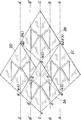
Classifications
-
- B—PERFORMING OPERATIONS; TRANSPORTING
- B29—WORKING OF PLASTICS; WORKING OF SUBSTANCES IN A PLASTIC STATE IN GENERAL
- B29C—SHAPING OR JOINING OF PLASTICS; SHAPING OF MATERIAL IN A PLASTIC STATE, NOT OTHERWISE PROVIDED FOR; AFTER-TREATMENT OF THE SHAPED PRODUCTS, e.g. REPAIRING
- B29C45/00—Injection moulding, i.e. forcing the required volume of moulding material through a nozzle into a closed mould; Apparatus therefor
- B29C45/0053—Injection moulding, i.e. forcing the required volume of moulding material through a nozzle into a closed mould; Apparatus therefor combined with a final operation, e.g. shaping
- B29C45/006—Joining parts moulded in separate cavities
- B29C45/0062—Joined by injection moulding
-
- B—PERFORMING OPERATIONS; TRANSPORTING
- B29—WORKING OF PLASTICS; WORKING OF SUBSTANCES IN A PLASTIC STATE IN GENERAL
- B29C—SHAPING OR JOINING OF PLASTICS; SHAPING OF MATERIAL IN A PLASTIC STATE, NOT OTHERWISE PROVIDED FOR; AFTER-TREATMENT OF THE SHAPED PRODUCTS, e.g. REPAIRING
- B29C45/00—Injection moulding, i.e. forcing the required volume of moulding material through a nozzle into a closed mould; Apparatus therefor
- B29C45/17—Component parts, details or accessories; Auxiliary operations
- B29C45/26—Moulds
- B29C45/33—Moulds having transversely, e.g. radially, movable mould parts
-
- B—PERFORMING OPERATIONS; TRANSPORTING
- B29—WORKING OF PLASTICS; WORKING OF SUBSTANCES IN A PLASTIC STATE IN GENERAL
- B29C—SHAPING OR JOINING OF PLASTICS; SHAPING OF MATERIAL IN A PLASTIC STATE, NOT OTHERWISE PROVIDED FOR; AFTER-TREATMENT OF THE SHAPED PRODUCTS, e.g. REPAIRING
- B29C45/00—Injection moulding, i.e. forcing the required volume of moulding material through a nozzle into a closed mould; Apparatus therefor
- B29C45/17—Component parts, details or accessories; Auxiliary operations
- B29C45/26—Moulds
- B29C45/37—Mould cavity walls, i.e. the inner surface forming the mould cavity, e.g. linings
-
- E—FIXED CONSTRUCTIONS
- E04—BUILDING
- E04F—FINISHING WORK ON BUILDINGS, e.g. STAIRS, FLOORS
- E04F10/00—Sunshades, e.g. Florentine blinds or jalousies; Outside screens; Awnings or baldachins
- E04F10/08—Sunshades, e.g. Florentine blinds or jalousies; Outside screens; Awnings or baldachins of a plurality of similar rigid parts, e.g. slabs, lamellae
Definitions
- the present invention relates to an awning member molded product and an awning capable of efficiently suppressing a temperature rise, and more particularly to an injection molded product of a member constituting a awning having a fractal structure and an awning formed by using a plurality of the same. .
- Patent Document 1 includes, as an awning having a fractal structure, four basic elements having a dihedral shape that is a quadrangle when viewed from the plane, arranged so as to be adjacent to each other on the left, right, front, back, and top and bottom. There are gaps between the elements, but it is disclosed that each basic element is arranged such that these gaps become zero when viewed from the maximum light shielding direction inclined by a predetermined angle.
- Patent Document 1 describes forming a fractal structure (a member for awning) by cutting and bending a part of a plastically deformable plate.
- the awning member disclosed in Patent Document 1 has a problem that it takes time to manufacture and it is difficult to obtain a sufficient strength.
- An object of the present invention is to provide an awning member molded product that is easy to manufacture and has high strength, and an awning formed by using a plurality of these.
- the sunshade member molded article according to the present invention is such that four basic elements of a dihedral shape that is a quadrangle when viewed from above are arranged so as to be adjacent to each other on the left, right, front, back, and top and bottom.
- An element, a second basic element arranged on either the left or right side of the first basic element, a third basic element arranged either before or after the first basic element, and first to third It consists of a fourth basic element arranged above the basic element, and there are gaps between the basic elements, but when viewed from the maximum light-shielding direction inclined by a predetermined angle, these gaps become zero.
- a basic element of the fractal structure formed by injection molding in which each basic element is disposed on the first basic element, the second basic element, the third basic element, and the fourth basic element.
- the butt part is joined during injection molding Together it is, is characterized in that the butt portion is also bonded during injection molding of the second basic element and the third basic element.
- each basic element having a tetrahedron shape that is a quadrilateral when viewed from the plane are arranged so as to be adjacent to each other in the left-right, front-back, and top-bottom directions, and the first basic element at the reference position and the left and right of the first basic element A second basic element arranged in any one, a third basic element arranged either before or after the first basic element, and a fourth arranged above the first to third basic elements. There are gaps between the basic elements, but each basic element is such that these gaps are zero (substantially zero) when viewed from the maximum light-shielding direction inclined by a predetermined angle.
- a member for sunshade having a fractal structure in which is disposed is known.
- dihedral shape means having a dihedral body part composed of two triangular plate parts, and includes a part protruding from the dihedral body part. Is also included in this.
- the dihedron shape including the part projecting with respect to the dihedron main body part is a large dihedron joined so that two large triangular parts are inverted V-shaped, and two small triangular parts are V-shaped.
- the sunshade member is, for example, installed on the rooftop of a building to block sunlight, and the installation surface is usually horizontal (although not limited to this). During this installation, the lower sides of the first to third basic elements are placed on the horizontal plane, and the ridge lines of the basic elements are inclined at a predetermined angle (30 to 40 ° with respect to the horizontal plane) with respect to the vertical plane. It is done.
- the awning member has a symmetrical central plane that bisects the first basic element and the fourth basic element in a symmetrical manner at the center thereof, and the second and third basic elements are arranged with respect to the symmetrical central plane. Are arranged symmetrically with each other.
- the gap between the basic elements is smaller than the gap when viewed from the front and the plane (substantially zero and
- the direction that is on the symmetry center plane and that is orthogonal to the ridge line direction is the “maximum light shielding direction”.
- the “maximum light shielding direction” can also be referred to as a direction connecting the abutting portion between the first basic element and the fourth basic element and the abutting portion between the second basic element and the third basic element.
- the angle of the portion of the corner portion of the first basic element at the reference position that is the corner portion of the molded member for sunshade is 90 °
- the second basic of the corners of the element and the third basic element the angle of the part which is the corner of the molded part for the awning is slightly smaller than 90 °
- the awning member is molded out of the corners of the fourth basic element.
- the angle of the portion that is the corner of the product is preferably greater than 90 °.
- the shape of the awning member molded product in the front view when the ridge line is set at the center is formed by the corners of the fourth basic element with the lower surfaces of the first, second and third basic elements as the bottom sides (slanted sides). It is preferable that the vertical angle is a right isosceles triangle of 90 °. In this case, the parts constituting each basic element (middle triangle plate part, middle triangle hole and each dihedron) are also right-angled isosceles triangles. If it does in this way, when assembling the awning member molded product, it is possible to easily align the adjacent awning member molded products by using these right isosceles triangles as a reference.
- a conventional awning member is manufactured by forming a triangular hole and a bent portion by cutting and bending a part of a plastically deformable plate material, and surrounds the size of the triangular hole.
- the first basic element, the second basic element, the third basic element, and the fourth basic element are joined at the abutting portion by making the size slightly smaller than the size of the three triangular plate portions. .
- joining of the butted portion between the second basic element and the third basic element is impossible unless welding is performed later, which is disadvantageous in terms of strength. .
- the awning member is an injection-molded product made of synthetic resin.
- the butt portion between the second basic element and the third basic element that could not be necessarily joined is joined at the time of injection molding. In this way, strength improvement is achieved.
- each basic element is arranged such that four dihedrons that are quadrangular when viewed from above are adjacent to each other in the left-right, front-back, and top-bottom directions, and the first dihedron at the reference position and the first two
- the second dihedron arranged on either the left or right side of the face body, the third dihedron arranged on either the front or back side of the first dihedron, and the first to third dihedrons.
- the fourth dihedron and the butted portion between the dihedrons are joined at the time of injection molding.
- This basic element can itself be a awning member molded product (single molded product that is not an assembly of a plurality of parts) (in this case, the dihedron is the basic element in claim 1). Become.). Further, an element (extended basic element) in which the four basic elements are arranged so as to be adjacent to each other on the left, right, front, back, and top and bottom can be used as a sunshade molded member. In any case, a plurality of (a large number) of the awning member molded products are continuously installed to form a awning that covers a required range.
- Such an awning uses a dihedron that is a quadrangle when viewed from the plane as a minimum unit, is adjacent to the first dihedron at the reference position, the first dihedron, and shares one vertex with each other. Are adjacent to the first dihedron, share the other apex of the first dihedron, and collinear with the other side of the first dihedron.
- Four dihedrons that share one vertex and have a fourth dihedron whose diagonals are on the same straight line are the basic elements, and the first basic element at the reference position is adjacent to the first basic element.
- a second basic element that shares one vertex with each other and whose sides are on the same straight line, and the first basic A third basic element that is adjacent to the element and shares the other vertices of the first basic element and is collinear with the other side of the first basic element; Adjacent to an element, sharing one vertex with each other, one side being on the same straight line, adjacent to the first basic element, sharing one vertex with each other, and having diagonal lines on the same straight line Fractal structure in which each basic element is arranged so that there is no gap when viewed from the maximum light-shielding direction inclined at a predetermined angle. Awning.
- the maximum light shielding direction is made to coincide with the axial direction of the injection molding apparatus.
- the contour shape of the same cross section is a hollow shape extending in that direction, and using this hollow shape, slide here A core is inserted.
- slide here A core is inserted.
- the awning member molded article can be obtained by one injection molding.
- the slide core for example, a pair of slide cores approaching / separating along the ridgeline direction is used, and a plurality of pairs of slide cores approaching / separating along the ridgeline direction are used as necessary.
- the injection molding apparatus includes a first mold that has a convex portion corresponding to the gap and is applied from the peak side of the basic element, and a second mold that has a corrugated uneven portion and is applied from the valley side of the basic element;
- a cavity is formed by a slide core that moves along the ridgeline of the basic element, and one of the first and second molds is a fixed mold, and the other is a movable mold.
- through-holes are respectively provided at four corners forming a quadrangle when viewed from above, and the awning member molded products arranged next to each other are
- the connection is made possible by a joint having a protrusion fitted into the through-hole of the other awning member molded product and a projection fitted into the through-hole of the other awning member molded product.
- the through hole is preferably provided at the same time as the injection molding, and the joint is preferably formed as a synthetic resin injection molded product.
- Assembling of the awning using the joint is performed at the awning installation site such as the rooftop of the building, and the awning member molded products are arranged adjacent to each other, and the adjacent awning member molded products are connected by the joint. By repeating the work, the sunshade can be assembled efficiently.
- the awning is not limited to the one using the joint, and the awning can be formed using a reinforcing material and a wire instead.
- the sunshade is a unit formed by arranging a predetermined number of sunshade molded parts so that the ridge lines are continuous, and the unit is supported by a reinforcing material extending in the ridge line direction. It is said.
- the reinforcing material metal wire, metal wire, natural fiber or synthetic fiber rope can be used.
- the reinforcing material may be flexible and can be bent easily, or may not be flexible like a steel material.
- the reinforcing member and each awning member molded product can be fixed by, for example, an adhesive. Also, a projection is added to each awning member molded product, and holes, slits, etc. for supporting the reinforcing material are provided. You may make it form in a permite
- the reinforcing material when the reinforcing material has flexibility, the reinforcing material is sequentially inserted into the through holes of the awning member molded product using the through holes provided in the respective awning member molded products. If the reinforcing material is not flexible, a wire is inserted into the through-hole provided in each awning member molding, and the reinforcing material and the awning molding are formed by this wire. And may be combined.
- the reinforcing material has a length that protrudes from the awning member molded product at both ends, and each end of the reinforcing material is fixed to a pair of supporting materials arranged opposite to each other, so that one unit is a supporting material. Fixed to. A plurality of units are arranged in parallel at a pitch corresponding to the size of the sunshade member molded product (the length in the direction orthogonal to the ridgeline direction), and the sunshade member is used in one unit on one side.
- the support member may be a frame that is supported at four corners by pillars.
- the support material may be installed horizontally or may be installed so as to be inclined at a predetermined angle with respect to the horizontal.
- the support material that supports the reinforcing material is set according to the direction of the sunshade (east, west, south, north) and the elevation angle. For example, if you want to prevent sunlight during the summer day, you can set the ridge line to the south and set the elevation angle in accordance with the altitude of the sun. If you want to prevent the sun, turn the ridge line to the west and the elevation angle. Should be reduced to match the western day. In general, it is preferable to install the awning ridgeline in a substantially horizontal direction with the aim of passing most of the solar radiation in the winter and almost blocking out the solar radiation in the summer.
- a reinforcing material By using a reinforcing material, it can be easily assembled and has excellent strength, and can easily cope with the time and direction in which it is desired to prevent solar radiation.
- each basic element has a vertex shared with an adjacent basic element and another vertex not shared, the first basic element, the second, the third,
- the triangle ABC with the fourth basic element shared as B, C, G, the other vertex of the first basic element as A, and the two sides AB, AC as the base is installed approximately horizontally
- the point of symmetry of the point A in the horizontal direction with respect to the side BC is defined as D, and the angle F formed by ⁇ ADG is defined as the reference angle.
- ⁇ may be north latitude or south latitude.
- 113- ⁇ corresponds to the solar altitude at the summer solstice.
- the shape of the tetrahedron viewed from the second horizontal direction orthogonal to the first horizontal direction has a vertex a positioned on the installation surface, and the lower side is arranged on the lower side.
- One side of the large triangular portion which consists of two upper triangular portions bfc and dce arranged on the upper side so as to form a triangular opening bcd between the inverted triangular portion abd and the lower inverted triangular portion abd
- the angle between the straight line af forming the ridge line and the straight line ef forming the ridge line of the large dihedron is an angle ⁇ ° corresponding to the solar altitude in winter, and the straight line ac that bisects the large triangular part and the ridge line of the large dihedron May be an angle ⁇ ° ( ⁇ > ⁇ ) corresponding to the solar altitude in the summer (second sunshade installation mode).
- the point a When installing the second installation form, the point a is positioned on the installation surface, the points c, e, and f form a ridge line (maximum height), and the points b and d are 1/2. Form a line of height.
- the straight line ef is parallel to the installation surface, the angle formed by the straight line af and the straight line ef is the same as the angle formed by the straight line af and the installation surface, and the angle formed by the straight line ac and the straight line ef is the straight line ac and It is the same as the angle made with the installation surface.
- the opening has an effect of improving ventilation, and both light shielding and good ventilation are realized.
- the opening area / total area of the awning viewed from a certain direction is greatly different depending on the direction (angle). It is preferable to block sunlight in summer, but it is not preferable to block sunlight in winter.
- the angle between the straight line af and the straight line ef (installation surface) is an angle ⁇ ° corresponding to the solar altitude in winter, and the straight line ac and the straight line ef (installation surface)
- the angle ⁇ ° ( ⁇ > ⁇ ) corresponding to the solar altitude in the summer
- the sunlight can be blocked in the summer and the sunlight can be easily transmitted in the winter.
- it is easy to install at an appropriate angle including use in winter.
- ⁇ min 90 ⁇ (latitude + 23)
- ⁇ max 90 ⁇ (latitude ⁇ 23)
- ⁇ max 90 ⁇ (23 ⁇ latitude).
- it is.
- ⁇ min is the lowest solar altitude in the northern hemisphere on the winter solstice day, and ⁇ min ⁇ ⁇ min + 10 is less than ⁇ min + 10, which is the solar altitude one or two months after ⁇ reaches the lowest temperature. It is shown that the range of is preferable.
- ⁇ max is the highest solar altitude on the day of the summer solstice in the northern hemisphere, and is calculated differently for regions with latitudes greater than 23 ° and regions with latitudes greater than 23 °.
- ⁇ max ⁇ 10 ⁇ ⁇ max indicates that ⁇ is smaller than this ⁇ max and a range of ⁇ max ⁇ 10 or more, which is the solar altitude after one to two months when the actual maximum temperature is reached, is preferable.
- the awning member comprising four basic elements is an integral part of injection molding, and the first basic element, the second basic element, the third basic element, and the fourth basic element Not only the butting part, but also the butting part of the second basic element and the third basic element is joined at the time of injection molding, so that the sunshading member can be easily manufactured, and the strength of the sunshading member Will improve.
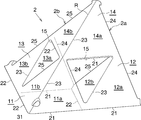
- FIG. 1 is a perspective view showing an embodiment of a molded product for an awning according to the present invention.
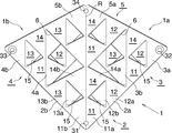
- FIG. 2 is a plan view of the same.
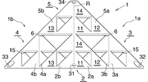
- FIG. 3 is a front view with the ridge line of the awning member molded product according to the present invention at the center.
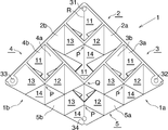
- FIG. 4 is a bottom view of the same.
- FIG. 5 is a view of the awning member molded product according to the present invention as seen from the maximum light shielding direction.
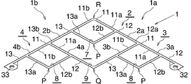
- FIG. 6 is a view of the awning member molded product according to the present invention as seen from the ridge line direction.
- FIG. 7 is an enlarged perspective view of the basic elements of the awning member molded product according to the present invention.
- FIG. 1 is a perspective view showing an embodiment of a molded product for an awning according to the present invention.
- FIG. 2 is a plan view of the same.
- FIG. 3 is a front view with the ridge line of the awning member molded product according to the present invention at the center.
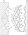
- FIG. 8 is a longitudinal cross-sectional view showing an example of a mold for manufacturing a awning member molded article according to the present invention.
- FIG. 9 is a perspective view showing a part of one embodiment of an awning assembled using a plurality of awning molded parts according to the present invention.
- FIG. 10 is a perspective view showing a part of another embodiment of an awning assembled by using a plurality of awning molded parts according to the present invention.
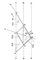
- FIG. 11 is a view showing a first installation form of an awning according to the present invention.
- FIG. 12 is a diagram (front view) showing a second installation form of an awning according to the present invention.
- FIG. 13 is a side view of the same.
- FIG. 14 is a plan view of the same.
- FIG. 15 is a sectional view of the same.
- FIG. 16 is a perspective view of the same.
- FIG. 17 is a plan view in the case where four tetrahedrons are joined with the ridgeline
- left and right in FIG. 1 are referred to as left and right, and up and down are referred to as up and down, and a direction orthogonal to these is referred to as front and back (the front side of the drawing in FIG. 1 is front).
- the shape of the single product obtained by injection molding is the shape shown in FIG. 1 to FIG. 9 and 10 can be obtained (a part thereof is shown).
- Such an awning has a fractal structure composed of a large number of awning molded parts (1), and the awning molded part (1) has four basic elements (2) (3) (4) (5 ), And each basic element (2) (3) (4) (5) itself is a dihedron (11) (12) (13) ( It has a fractal structure in units of 14).
- Each basic element (2) (3) (4) (5) has four dihedrons (11), (12), (13), and (14) that are quadrangular when viewed from the plane so that they are adjacent to each other on the left, right, front, back, and top and bottom
- the awning member molded product (1) has four basic elements (2), (3), (4), and (5) arranged so as to be adjacent to each other in the left-right, front-back, and top-bottom directions.
- the basic element (2), the second basic element (3) arranged to the right of the first basic element (2), and the third basic element arranged behind the first basic element (2) It consists of an element (4) and a fourth basic element (5) arranged above the first to third basic elements (2), (3) and (4).
- Each basic element (2), (3), (4), and (5) is a rectangle when viewed from the plane, and the awning member molded product (1) is also a rectangle when viewed from the plane.
- the ridgelines of the first and fourth dihedrons (11) and (14) included in the first and fourth basic elements (2) and (5) are continuous, and the awning forms a dihedral shape as a whole. This is the ridgeline (R) of the molded part (1).
- the ridge line (R) is inclined at a required angle (about 30 to 40 °) with respect to the horizontal plane.
- the four dihedrons (11) (12) (13) (14) constituting the basic element (2) (the same applies to the other basic elements (3), (4), and (5)).
- each of the dihedrons (11), (12), (13), and (14) forms side surfaces with the small triangular plate portions (11a), (12a), (13a), and (14a) that form the front surface.
- the first dihedron (11) is located on the horizontal plane and forms the two sides of the square from the intersection of the lower side (21) (22) and the lower side (21) (22) between the lower side (21) (22).
- the common side (23) that extends diagonally upward to form the ridge line (R), the upper side of the near side and the back side connecting the upper end of the common side (23) and the end of each lower side (21) (22) ( 24) (25).
- the second dihedron (12) includes a lower side (21) in the left-right direction in which the lower side (21) in the left-right direction of the first dihedron (11) is extended in the left-right direction, and the first dihedron (11).
- the third dihedron (13) includes a lower side (22) in the front-rear direction in which the lower side (22) in the front-rear direction of the first dihedron (11) is extended in the front-rear direction, and the first dihedron (11).
- the fourth dihedron (14) includes a common side (23) in which the common side (23) of the first dihedron (11) extends obliquely upward, and a front side of the second dihedron (12).
- a lower side (21) in the left-right direction parallel to the lower side (21) in the left-right direction of the first dihedron (11), and a front-rear direction parallel to the lower side (22) in the front-rear direction of the first dihedron (11) It consists of the lower side (22) of the direction.
- the small triangular plate portions (11a), (12a), and (14a) forming the front surfaces of the first, second, and fourth dihedrons (11), (12), and (14) are in the same plane (front surface).
- the small triangular plate part (12b) that forms the side surface of the second dihedron (12) is bent to the bottom side with respect to the front surface. Is formed with a triangular small triangular hole (15).
- the small triangular plate portions (11b), (13b), and (14b) that form the side surfaces of the first, third, and fourth dihedrons (11), (13), and (14) are on the same plane (side surface).
- the basic element (2) includes a dihedral body portion in which two middle triangular plate portions (2a) (2b) having a small triangular hole (15) in the central portion are joined via a ridgeline (R), It has a dihedral shape composed of small triangular plate portions (protruding portions) (12b) and (13a) that are bent toward the bottom surface with respect to the triangular plate portions (2a) and (2b).
- each small triangular hole (15) is slightly smaller than the size of the three triangular plate portions (11a) (12a) (14a) (11b) (13b) (14b) surrounding it.
- a predetermined thickness is secured between the adjacent triangular plate portions (11a) (12a) (14a) (11b) (13b) (14b), and the triangular plate portions (11a) (12a) (14a) (11b) ) (13b) (14b) are joined to each other at the butted portion.
- the basic elements (2), (3), (4), and (5) that are adjacent to each other on the left and right, front and rear, and top and bottom are also joined to each other by ensuring a predetermined thickness at each butted portion.
- the first, second and fourth basic elements (2), (3) and (5) are on the same plane (front surface), and the middle triangular plate forming the side surface of the second basic element (3) with respect to the front surface. Since the portion (3b) is bent toward the bottom surface side, a triangular middle triangular hole (6) is formed in the large triangular portion (1a) on the front surface. Further, the middle triangular plate portions (2b), (4b) and (5b) forming the side surfaces of the first, third and fourth basic elements (2), (4) and (5) are on the same plane (side surface).
- the sunshade molded part (1) has a dihedral body in which two large triangular plates (1a) (1b) having a middle triangular hole (6) at the center are joined via a ridgeline (R). It has a dihedral shape composed of a portion and a middle triangular plate portion (protruding portion) (3b) (4a) bent to the bottom side with respect to the large triangular plate portions (1a) (1b).
- the molded part for awning (1) is a basic element, and four of them are used in the same way as the above basic elements (2), (3), (4), and (5).
- an assembly of the awning member molded product (1) shown in FIG. 9 is obtained, and an awning having a necessary size is obtained by appropriately increasing the number of the awning member molded products (1) to be used. be able to.
- the portion of the corner portion of the first basic element (2) at the reference position that is the corner portion of the awning member molded product (1) (the corner on the lower side of FIG. 2)
- the angle of the part) is 90 °
- the ridge line (R) bisects this.
- the angle of the corner part (the corner part on the left and right in FIG. 2) that is the corner part of the sunshade molded part (1) are equal to each other and slightly smaller than 90 °, and therefore, the portion of the corner of the fourth basic element (5) that is the corner of the awning member molded product (1) (see FIG. 2).
- the angle of the upper corner is greater than 90 °.
- the awning member molded product (1) has the first, second and third basic elements (2) (3) (4 ) With the bottom surface (the hypotenuse) as the base (slope side), the apex angle formed by the corners of the fourth basic element (4) is a 90 degree right angled isosceles triangle.
- Each dihedron (11) (12) (13) (14) is also a right-angled isosceles triangle.
- the small triangle plate part (12b) bent to the bottom surface side of the second dihedron (12) and the small triangle bent to the bottom surface side of the third dihedron (13) A predetermined thickness is secured also at the abutting portion with the plate portion (13a), and the second dihedral body (12) and the third dihedral body of each basic element (2) (3) (4) (5)
- the strength of the basic elements (2), (3), (4), and (5) of the sunshade molded part (1) is greatly improved.
- the awning member molded product (1) when forming the awning member molded product (1) by the basic elements (2), (3), (4), and (5), it was bent to the bottom side of the second basic element (3) indicated by the arrow Q A predetermined thickness is secured at the abutting portion between the middle triangle plate portion (3b) and the middle triangle plate portion (4a) bent to the bottom surface side of the third basic element (4), and the second basic configuration.
- the element (3) and the third basic component (4) are joined together, whereby the strength of the awning member molded product (1) is further improved.
- the awning member molded product (1) is formed with the triangular holes (6) and (15) having different sizes as described above, so that the awning member molded product (1) is shown in FIGS. In any of the drawings up to this point, there are gaps at multiple locations (the portions not covered by the triangular plate portions (3b) (4a) (12b) (13a) beyond the triangular holes (6) and (15)). There is a shape.
- the awning member molded product (1) is viewed obliquely from above with the ridge line (R) in front (corresponding to viewing from the sun direction), as shown in FIG.
- the small triangular hole (15) Is blocked by the folded small triangular plate (12b) (13a), and the middle triangular hole (6) is folded by the bent middle triangular plate (3b) (4a).
- the gap in the member molded product (1) is substantially zero, thereby improving the light shielding property.
- Each triangular hole (6) (15) has an effect of improving ventilation, thereby realizing both light shielding properties and good ventilation.
- the awning member molded product (1) is a small part folded at the position indicated by the arrow P, that is, the bottom surface side of the second dihedron (12), as viewed from above in the ridgeline direction.
- the first basic element (2) And the small triangular plate portions (11a) and (11b) of the first dihedron (11) of the fourth basic element (5) on the other side (and the fourth dihedron (14 on the other side) )
- second cylindrical portions (second cylindrical portions) (8) extending in the ridge direction whose rhombus cross section is half the length of the first cylindrical portion (7).
- the portion indicated by the arrow Q that is, the middle triangular plate portion (3b) bent to the bottom surface side of the second basic element (3) and the middle triangular plate portion bent to the bottom surface side of the third basic element (4)
- a hollow cylindrical portion (third cylindrical portion) (9) having a V-shaped cross section and extending in the ridge line direction is formed.
- the peripheral walls of the cylindrical portions (7), (8), and (9) are cut out at locations corresponding to the gaps (triangular holes (6) and (15)).
- slide cores (43) (44) (45) having a cross-sectional shape corresponding to the cross-sectional shape of the cylindrical portions (7), (8), and (9) are replaced with the cylindrical portion ( 7) Insert into the inside of (8) and (9) from both sides in the ridgeline direction (front side and back side of the paper surface of FIG. 6), and awning by a pair of molds (41) and (42) from the top and bottom sides of FIG. It can be seen that the awning member molded product (1) can be obtained by injection molding by sandwiching the member molded product (1).
- this awning member molded product (1) in order to obtain this awning member molded product (1), as shown in FIG. 8, it has a V-shaped concave surface (41a) and is applied from the mountain side of the awning member molded product (1).
- a movable mold (41) that moves in the left-right direction (direction perpendicular to the ridge line direction) and a fixed mold (42) that has a corrugated uneven surface (42a) and is applied from the valley side of the awning molded part (1) )
- a plurality of pairs of slide cores (43) (44) (45) that approach and separate from each other in the ridgeline direction of the awning member molded product (1).
- the V-shaped concave surface (41a) of the movable mold (41) forms the surface of the large triangular portion (1a) (1b) of the molded product for the sunshade (1), and is formed on the concave surface (41a).
- the middle triangle plate (3b) fitted to a certain middle triangle hole (6) and folded to the bottom surface side of the second basic element (3) and the bottom surface side of the third basic element (4)
- a second convex portion (41c) forming the surface of the middle triangular plate portion (4a), a middle triangular plate portion (3b) connected to the second convex portion (41c) and the second basic element (3);
- a third convex portion (41d) that fits into each small triangular hole (15) of the middle triangular plate portion (4a) of the third basic element (4) is provided.
- the slide core (43) (44) (45) has a rhombus cross section inserted into the first cylindrical portion (7) and has a shape that does not interfere with the second convex portion (41c) in the central portion.
- the fixed mold side core part (44) having a diamond-shaped cross section inserted into the second cylindrical part (8), and the third cylindrical part (9)
- a central core (45) having a substantially square cross section inserted into a portion where the second convex portion (41c) of the movable mold (41) is not inserted is used.
- the corrugated uneven surface (42a) of the fixed mold (42) is formed with a step portion (42b) for forming a non-thick part by contacting the slide core (43).
- the awning member molded product (1) has four corners (the lower end in the ridgeline direction of the first basic element (2), the second basic element ( In the right lower end of 3), the rear lower end of the third basic element (4) and the upper end of the fourth basic element (5) in the ridge line direction, respectively, through holes (31), (32), (33) ( 34) is provided.
- the adjacent awning member molded products (1) are fitted into the through holes (31) (32) (33) (34) of one awning member molded product (1) as shown in FIG.
- Projections (35a) (36a) (37a) to be inserted and projections (35b) (36b) (35b) to be inserted into the through holes (31) (32) (33) (34) of the other sunshade molded part (1) 37b) can be connected by joints (35) (36) (37).
- the joints (35), (36) and (37) have a first basic element (2) and second and third basic elements (3) and (4) (adjacent to the left and right and front and rear).
- a first joint (35) having two upward projections (35a) and (35b) for connecting the matching basic elements), a first basic element (2) and a fourth basic element (5)
- a second joint (36) having one upward projection (36a) and one downward projection (36b) for connecting the basic elements which are displaced from front to back and from side to side and are adjacent to each other in the vertical direction;
- One upward projection (37a) and 1 for connecting the three basic elements (3), (4) and the fourth basic element (5) (basic elements arranged side by side in the front-rear or left-right direction)
- a third joint (37) having two downward projections (37b) is used.
- the awning member moldings (1) are placed on the right side and the rear side of the awning moldings (1) arranged at predetermined positions. Side by side, these are joined by a first joint (35), and then a new awning part molding (1) is placed on top of the three awning part moldings (1) joined together, and these are joined together in the first and It is only necessary to connect the second joints (35) and (36), and by repeating this operation, an arbitrary number of sunshade molded parts (1) can be arranged on the left, right, front, back, and top and bottom. The sunshade can be assembled very efficiently.
- the awning it is not limited to the one using the joint (37), but instead of using a reinforcing material (51) and a wire (52) as shown in FIG. An awning can also be formed.
- one unit (50) is formed by arranging a predetermined number of awning member molded articles (1) so that ridge lines (R) are continuous, and the unit (50) is formed of ridge lines. It is supported by a reinforcing material (51) extending in the (R) direction. A plurality of units (50) thus obtained are arranged in parallel to form an awning.
- the reinforcing member (51) and each of the awning member molded products (1) can be coupled by winding the wire (52) around the reinforcing member (51).
- the reinforcing member (51) and each sunshade molded member (1) may be bonded in advance with an adhesive or the like.
- the awning When installing the awning using the unit (50) formed as described above, use a support material of a high-strength material such as metal (for example, a U-shaped iron angle) to cover the awning.
- a support material of a high-strength material such as metal (for example, a U-shaped iron angle) to cover the awning.
- the frame along the outer edge of the frame is manufactured, holes for passing the reinforcing material (51) are formed on the two opposite sides of the frame at a required interval, and the end of the reinforcing material (51) is fixed to the frame.
- the awning can be installed at a predetermined height by supporting the four corners of the frame with metal posts (for example, aluminum angles).
- the awning obtained in this way it is easy to assemble by using the reinforcing material (51), and it is easy to adapt to the size and shape of the place where you want to install the awning, and you want to prevent solar radiation It is easy to deal with time and direction.
- the awning does not partially fall in a lump and is excellent in strength against falling snow or falling foreign matter from above.
- An awning formed by installing multiple parts of the awning parts (1) in succession can be installed anywhere in the world, thereby cooling the city without using energy and eliminating the heat island. Can contribute. In order to enhance this effect, it is necessary that the awning be installed at the correct angle. For this purpose, it is first necessary to determine a reference point and set a reference angle.
- the awning member molded product (1) has the shape shown in FIG.
- the first basic element (2) of the awning member molded product (1) (the same applies to the other basic elements (3), (4) and (5)) is the smallest dihedron that is square when viewed from the plane.
- the face body (12) is adjacent to the first dihedron (11), shares the other vertex c of the first dihedron (11), and is the same as the other side of the first dihedron (11).
- the sunshade member molded article (1) has these four dihedrons (11), (12), (13), and (14) as basic elements, the first basic element (2) at the reference position, Adjacent to the first basic element (2), adjacent to the first basic element (2), adjacent to the second basic element (3) sharing one vertex B and having one side on the same straight line,
- the third basic element (4) that shares the other vertex C of the first basic element (2) and is collinear with the other side of the first basic element (2)
- Adjacent to the third basic element (3) (4) share one vertex E, F, one side is on the same straight line, adjacent to the first basic element (2), It consists of a fourth basic element (5) that shares one vertex G and whose diagonals are on the same straight line.
- each basic element (2) (3) (4) (5) has a vertex that is shared with an adjacent basic element and another vertex that is not shared.
- Vertices shared by (2) and the second, third, and fourth basic elements (3), (4), and (5) are B, C, and G, and the other vertices of the first basic element (2) Is a triangle ABC with two sides AB and AC as bases, and a horizontal symmetry point of the point A with respect to the side BC is D, and an angle F formed by ⁇ ADG is a reference angle. .
- the light shielding direction is maximized and the most effective can be obtained.
- the angle of the sun varies depending on the latitude, so the angle F can be expressed using the latitude as a parameter.
- the temperature is the highest and the sunlight is intense from the end of July to the beginning of August, and the time is from 12:00 to 14:00.
- setting the sun's elevation angle to 72 ° in the metropolitan area that is, around 36 ° north latitude, and 108- ⁇ in the region of north latitude ⁇ ° are most effective.
- the amount of direct sunlight in summer is highest at the time of the summer solstice, but the Earth's surface temperature rises for one month from one month to two months later. If the sun's direct sunlight at the sun's altitude at this time is shielded, the temperature rise on the surface can be prevented.
- the south-south altitude of the sun at the summer solstice is 90- ( ⁇ -23) ° ( ⁇ -23.4, but 0.4 ° has little effect on the effect. -23). However, the temperature becomes highest during one month, one month to two months later, and the highest after about 1.5 months.
- the solar altitude at this time is 5 ° lower than the south-central altitude at the time of the summer solstice, and is 90- ( ⁇ -23) -5 ⁇ 108- ⁇ °.
- the direct sunlight is shielded most effectively, so there is no gap between the sunshade when viewed from infinity in this direction (this is the first direction).
- the shape is achieved by the fact that the angle from point D to point G in FIG. 11 is on the sun's direct sunlight angle, that is, on the 108 (or 108.4) - ⁇ line.
- the direction of the DG of FIG. 11 is aligned with the direction of the sun, and the difference between the desired time and noon is 1. What is necessary is just to increase / decrease 12 degrees per hour.
- ⁇ may be north latitude or south latitude.
- 113-S- ⁇ corresponds to the solar altitude at the highest summer temperature in the case of S ⁇ 5. Therefore, by setting 108 ⁇ ⁇ F ⁇ 113 ⁇ , a preferable awning can be obtained in an area where the latitude is ⁇ .
- S + T is an index corresponding to the type of awning necessary to cover regions all over the world.
- 108 ⁇ ⁇ F ⁇ 113 ⁇ is the condition for optimizing the sunshade effect when ⁇ ⁇ 23, and 113 ⁇ S ⁇ ⁇ F ⁇ 113 + T ⁇ when ⁇ ⁇ 23 (where S: 5 to 10 Constant, T: a constant of 0 to 5) is an appropriate condition including the ease of manufacture of the awning member molded article (1) and the ease of storage and management.
- the awning member molded product (1) is an injection molded product made of synthetic resin, and the butted portion between the second basic element (3) and the third basic element (4) is joined.
- the abutting portion coincides with the point D in the above condition, so that the point D is not a virtual point. It is an actual point that can be specified in the awning member molded product (1), and the angle F of the awning member molded product (1) can be easily measured.
- ⁇ Installing the sunshade as described above facilitates installation at an appropriate angle when installing in different regions around the world.
- the following may be performed. The following installation is easy to implement by using the unit (50) supported by the reinforcing material (51) shown in FIG.
- FIG. 12 is regarded as a front view
- FIG. 13 is regarded as a side view
- the orthogonal direction is referred to as front and back (the front side of the paper in FIG. 12 is front). Accordingly, in FIG. 13, the right is front, the left is rear, and the top and bottom are up and down.
- FIG. 14 right is front, left is rear, top is left, and bottom is right.
- the “front view” and “side view” are determined for convenience, and the front face at the time of installation does not need to coincide with this “front face”.
- the sunshade member molded product (1) has the shape shown in FIG.
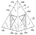
- FIG. 12 shows the shape (front view) seen from the first horizontal direction (front) where the area of the opening is maximum, and the basic element (2) is composed of two large triangular parts (61) (62).
- It is a tetrahedron composed of a small dihedron (20) coupled to a large dihedron (10) so as to be symmetrical with the part.
- FIG. 13 shows a shape (side view) seen from a second horizontal direction (left side of FIG. 12) orthogonal to the first horizontal direction, which shows a large triangular portion (61). .
- a straight line E forms a winter solar altitude ⁇ ° from a point a on the installation surface A
- a straight line F similarly forms a summer solar altitude ⁇ ° from the point a.
- a straight line is drawn from the point a so as to intersect the straight lines B and C in parallel with the straight line bc connecting the intersection point b between the straight line B and the straight line E and the intersection point c between the straight line C and the straight line F. Let e be the intersection with the straight line C.
- the straight line ac is a line that bisects the large triangular portion (61).
- the triangle abd, the triangle bfc, and the triangle dce are made of an awning material, and the triangle bcd is an opening.
- the shape of the basic element (2) viewed from the second horizontal direction orthogonal to the first horizontal direction is such that the lower inverted triangle part abd (61a) arranged on the lower side and the lower inverted triangle part abd (61a) and two upper triangular portions dce (61b) and bfc (61c) arranged on the upper side so as to form a triangular opening bcd (61d).
- the shape seen from the right side of FIG. 12 (large triangular portion (62)) is also the same as the shape shown in FIG. Accordingly, as shown in FIG. 15, the large triangular portion (61) on the left side is provided with the opening bcd (61d), and the large triangular portion (62) on the right side is also provided with the opening b'cd '( 62d), and these two openings (61d) and (62d) are at the same height, and in FIG. 13, they overlap. Accordingly, the sunlight in the paper surface direction of FIG. 13 and the left-right direction of FIG. 15 can pass through one opening (61d) and pass through the other opening (62d) without being interrupted.
- A shows an awning installation surface
- the vertices a and a ′ of the large triangular portions (61) and (62) and the ridge line g of the small dihedron (20) are on this installation surface.
- C indicates the height of the ridgeline (shade height), and the other two vertices e and f of the large triangle (61) (62) forming the ridgeline of the large dihedron (10)
- the point c in the middle is on this installation surface
- B indicates a half height surface
- points b, d which are the joints of the large dihedron (10) and the small dihedron (20).
- b 'and d' are on this 1/2 height plane.
- A, B, and C are mutually parallel at equal intervals.
- FIG. 14 is a plan view of the basic element (2) of FIGS. 12 and 13 as viewed from above.
- the straight lines A, B, C and points a, b, c, d, e, f are the same as those shown in FIG. 13, and the straight lines A ′, B ′ and points a ′, b ′, d ′ are the same as those shown in FIG. Then, it is the place where each overlapped.
- the large triangular portion (62) not shown in FIG. 13 is similar to the large triangular portion (61) shown in FIG.
- the parallel lines A, B, C, B ′, A ′ are equally spaced, and the distance is not particularly limited. However, the distance from which the triangle abd becomes a substantially equilateral triangle when viewed from the direction of FIG. preferable.
- these openings (61d) and (62d) are formed appropriately smaller than the awning material part, and the awning material is attached to each other at each point. It is connected with.
- the actual openings (61d) and (62d) are indicated by solid lines, and the imaginary lines necessary to form the openings (61d) and (62d) are indicated by two-dot chain lines.
- FIG. 16 shows an example of the basic element (2) viewed from an oblique direction.
- the basic element (2) has three different views as shown in FIGS. 12 to 14, and therefore, the view seen from the oblique direction also varies greatly depending on the viewing direction and angle.
- the triangular openings (61d) and (62d) are formed into triangular portions (20a) and (20b) of a small dihedron (20). A part of the gap is blocked by, and the gap through which sunlight can pass varies depending on the direction.
- the basic elements (2) are arranged so that these gaps are zero when viewed from the maximum light-shielding direction inclined at a predetermined angle in summer.
- the basic elements (2) are arranged so that these gaps are zero when viewed from the maximum light-shielding direction inclined at a predetermined angle in summer.
- a straight line af forming one side of the large triangular portion 61 and a straight line ef forming a ridge line of the large dihedron 10 Is defined as an angle ⁇ ° corresponding to the solar altitude in winter
- a straight line ac that bisects the large triangular portion (61) and a straight line ef that forms the ridgeline of the large dihedron (10) (parallel to the installation surface A) ) Is an angle ⁇ ° ( ⁇ > ⁇ ) that corresponds to the solar altitude in the summer, so that it can block sunlight in the summer and make the sunlight more transparent in the winter.
- FIG. 17 is a plan view of a configuration (an example of an awning component) in which four basic elements (2) shown in FIG. 14 are connected.
- This sunshade component is arranged in front of the first basic element (2A) in the reference position, the first basic element (2A), and the f and second basic elements of the first basic element (2A)
- the second basic element (2B) in which e2 of (2B) is overlapped and connected, and the first basic element (2A) and the second basic element (2B) are arranged to the right of the first basic element (2B).
- the basic element (2A) a and the third basic element (2C) e3 are overlapped and connected, and the second basic element (2B) a2 and the third basic element (2C) f3
- the third basic element (2C) that is overlapped and connected, and the first basic element (2A) is arranged to the left of the first basic element (2A) and the second basic element (2B).
- the third basic element (2C) and the fourth basic element (2D) are arranged below the first basic element (2A) and the second basic element (2B).
- the ridge line (straight line C) in (2C) and the straight line A in the first basic element (2A) and the second basic element (2B) are on the same straight line
- the ridge line (straight line in the fourth basic element (2D)) C) and the straight line A in the first basic element (2A) and the second basic element (2B) are on the same straight line.
- Each of the four basic elements (2A), (2B), (2C), and (2D) in FIG. 17 is replaced with an awning component that includes the four basic elements (2A), (2B), (2C), and (2D) shown in FIG.
- an awning component comprising 16 basic elements (2A) (2B) (2C) (2D) is obtained.
- the angle ⁇ ° shown in FIG. 13 varies depending on the latitude of the area where the awning is used.
- the sunshade direction (the direction of line C in FIG. 13) is reversed from north to south.
- the angle ⁇ also changes depending on the latitude of the area where this awning is used, and is 23 ° (23.4 °, which is the inclination of the earth's earth axis, but 0.4 ° has almost no effect on the effect, so 23 ° is assumed. ) It changes depending on higher latitude or lower latitude.
- ⁇ max is the highest solar altitude in the summer solstice, and ⁇ is smaller than this ⁇ max and actually reaches the highest temperature.
- the sunshade direction (the direction of line C in FIG. 13) is reversed from north to south.
- the sunshade direction (the direction of line C in FIG. 13) is reversed from north to south.
- the size of one side of the triangle is 100 mm or less, and preferably 50 mm or less. By doing so, the sunshade effect is large (the increase in the ground temperature in the lower part is small).
- the present invention provides an awning member molded product and an awning that are easy to manufacture and have high strength. By using this, the temperature rise can be efficiently suppressed without using energy, which can contribute to the elimination of heat islands.
Landscapes
- Engineering & Computer Science (AREA)
- Manufacturing & Machinery (AREA)
- Mechanical Engineering (AREA)
- Architecture (AREA)
- Civil Engineering (AREA)
- Structural Engineering (AREA)
- Building Awnings And Sunshades (AREA)
Abstract
Description
(2)(3)(4)(5) 基本要素
(2A)(2B)(2C)(2D) 基本要素
(10) 大きい二面体
(11)(12)(13)(14) 二面体
(20) 小さい二面体
(20a)(20b) 小さい三角形部
(31)(32)(33)(34) 貫通孔
(35)(36)(37) ジョイント
(50) ユニット
(51) 補強材
(61)(62) 大きい三角形部
(61a)(62a) 下側逆三角形部
(61b)(62b)(61c)(62c) 上側三角形部
(61d)(62d) 三角形の開口部
Claims (10)
- 平面から見て四角形となる二面体形状の4つの基本要素が左右、前後および上下に隣り合うように配置されたもので、基準位置にある第1の基本要素と、第1の基本要素の左右いずれかに配置された第2の基本要素と、第1の基本要素の前後いずれかに配置された第3の基本要素と、第1から第3までの基本要素の上方に配置された第4の基本要素とからなり、各基本要素間には隙間が存在するが、所定角度傾斜した最大遮光方向から見た場合に、これらの隙間がゼロとなるように各基本要素が配置された射出成形によって形成されたフラクタル構造の日除け用部材成形品であって、第1の基本要素と第2の基本要素、第3の基本要素および第4の基本要素との突き合わせ部が射出成形時に接合されているとともに、第2の基本要素と第3の基本要素との突き合わせ部も射出成形時に接合されていることを特徴とする日除け用部材成形品。
- 各基本要素は、平面から見て四角形となる4つの二面体が左右、前後および上下に隣り合うように配置されたもので、基準位置にある第1の二面体と、第1の二面体の左右いずれかに配置された第2の二面体と、第1の二面体の前後いずれかに配置された第3の二面体と、第1から第3までの二面体の上方に配置された第4の二面体とからなり、各二面体同士の突き合わせ部が射出成形時に接合されていることを特徴とする請求項1の日除け用部材成形品。
- 隙間に対応する凸部を有し基本要素の山側から当てられる第1の金型と、波形の凹凸部を有し基本要素の谷側から当てられる第2の金型と、基本要素の稜線に沿って移動するスライドコアとが使用されるとともに、第1および第2の金型のいずれか一方が固定側金型、他方が可動側金型とされて、これらの金型が日除け用部材成形品の最大遮光方向を軸方向として対向するように配置された射出成形によって形成されていることを特徴とする請求項1または2の日除け用部材成形品。
- 請求項1から3までのいずれかの日除け用部材成形品が複数連続して設置されることで形成された日除け。
- 各日除け用部材成形品において平面から見て四角形を形成している4つの角部に、隣り合って配置される日除け用部材成形品同士を結合するための貫通孔がそれぞれ設けられている請求項4の日除け。
- 隣り合う日除け用部材成形品同士は、一方の日除け用部材成形品の貫通孔に嵌め入れられる突起と他方の日除け用部材成形品の貫通孔に嵌め入れられる突起とを有するジョイントによって接続されていることを特徴とする請求項5の日除け。
- 所定数の日除け用部材成形品が稜線が連続するように配置されることで1つのユニットが形成されており、該ユニットは、稜線方向に延びる補強材で支持されていることを特徴とする請求項5の日除け。
- 第1の基本要素と、第2、第3、第4の基本要素とが共有する頂点をB,C,Gとし、第1の基本要素の他の頂点をAとし、2辺AB,ACを底辺とする3角形ABCを略水平に設置したとき、点Aの辺BCに対する水平方向の対称点をDとし、∠ADGのなす角度F(°)が、
θ≧23で113-S-θ≦F≦113+T-θ、
θ<23でF=90±10(ここで、θは日除けの設置される場所の緯度であり、Sは5以上10以下の適宜な数、Tは0以上5以下の適宜な数)となされていることを特徴とする請求項4の日除け。 - 日除け用部材成形品は、開口部の面積が最大となる第1の水平方向から見た形状が逆V字状となるように2つの大きい三角形部が結合された大きい二面体と、2つの小さい三角形部がV字状となるように結合されて大きい二面体の上半部と対称となるように大きい二面体に結合された小さい二面体とからなる四面体を有しており、第1の水平方向に直交する第2の水平方向から見た四面体の形状が、設置面に位置させられる頂点aを有し下側に配置された下側逆三角形部abdと、下側逆三角形部abdとの間に三角形の開口部bcdを形成するように上側に配置された2つの上側三角形部bfcおよびdceとからなり、大きい三角形部の1つの辺を形成する直線afと大きい二面体の稜線を形成する直線efとのなす角が冬季の太陽高度に対応する角度α°とされ、大きい三角形部を二等分する直線acと大きい二面体の稜線を形成する直線efとのなす角が夏季の太陽高度に対応する角度β°(β>α)とされていることを特徴とする請求項4の日除け。
- αmin<α<αmin+10かつβmax-10<β<βmax、ただし、αmin=90-(緯度+23)かつβmax=90-(緯度-23)またはβmax=90-(23-緯度)とされている請求項9の日除け。
Priority Applications (4)
| Application Number | Priority Date | Filing Date | Title |
|---|---|---|---|
| AU2010260919A AU2010260919B2 (en) | 2009-06-18 | 2010-06-16 | Molded sunshade member and sunshade |
| KR1020127001148A KR101741858B1 (ko) | 2009-06-18 | 2010-06-16 | 차양용 부재 성형품 및 차양 |
| US13/378,626 US8842256B2 (en) | 2009-06-18 | 2010-06-16 | Awning-member molded article and awning |
| CN201080036470.3A CN102803631B (zh) | 2009-06-18 | 2010-06-16 | 遮阳罩用构件成形品及遮阳罩 |
Applications Claiming Priority (8)
| Application Number | Priority Date | Filing Date | Title |
|---|---|---|---|
| JP2009145179 | 2009-06-18 | ||
| JP2009-145179 | 2009-06-18 | ||
| JP2009-182211 | 2009-08-05 | ||
| JP2009182211A JP2011032808A (ja) | 2009-08-05 | 2009-08-05 | 日除け |
| JP2009-287154 | 2009-12-18 | ||
| JP2009287154A JP5002000B2 (ja) | 2009-06-18 | 2009-12-18 | 日除け用部材成形品および日除け |
| JP2010-087701 | 2010-04-06 | ||
| JP2010087701A JP5066215B2 (ja) | 2010-04-06 | 2010-04-06 | 日除け |
Publications (1)
| Publication Number | Publication Date |
|---|---|
| WO2010147128A1 true WO2010147128A1 (ja) | 2010-12-23 |
Family
ID=43356444
Family Applications (1)
| Application Number | Title | Priority Date | Filing Date |
|---|---|---|---|
| PCT/JP2010/060161 Ceased WO2010147128A1 (ja) | 2009-06-18 | 2010-06-16 | 日除け用部材成形品および日除け |
Country Status (1)
| Country | Link |
|---|---|
| WO (1) | WO2010147128A1 (ja) |
Cited By (3)
| Publication number | Priority date | Publication date | Assignee | Title |
|---|---|---|---|---|
| JP2014034857A (ja) * | 2012-08-10 | 2014-02-24 | Kashii:Kk | 日除け |
| CN107268829A (zh) * | 2017-07-27 | 2017-10-20 | 华南理工大学建筑设计研究院 | 一种组装式自承重绿墙 |
| US20190338527A1 (en) * | 2016-11-16 | 2019-11-07 | Fractal Japan Co., Ltd. | Sunshade |
Citations (2)
| Publication number | Priority date | Publication date | Assignee | Title |
|---|---|---|---|---|
| JPH05202591A (ja) * | 1991-05-24 | 1993-08-10 | Matsushita Electric Works Ltd | ひさし屋根 |
| JP2008196254A (ja) * | 2007-02-15 | 2008-08-28 | Kyoto Univ | 日よけ、放熱器、およびこれらの製造方法 |
-
2010
- 2010-06-16 WO PCT/JP2010/060161 patent/WO2010147128A1/ja not_active Ceased
Patent Citations (2)
| Publication number | Priority date | Publication date | Assignee | Title |
|---|---|---|---|---|
| JPH05202591A (ja) * | 1991-05-24 | 1993-08-10 | Matsushita Electric Works Ltd | ひさし屋根 |
| JP2008196254A (ja) * | 2007-02-15 | 2008-08-28 | Kyoto Univ | 日よけ、放熱器、およびこれらの製造方法 |
Cited By (4)
| Publication number | Priority date | Publication date | Assignee | Title |
|---|---|---|---|---|
| JP2014034857A (ja) * | 2012-08-10 | 2014-02-24 | Kashii:Kk | 日除け |
| US20190338527A1 (en) * | 2016-11-16 | 2019-11-07 | Fractal Japan Co., Ltd. | Sunshade |
| US10801210B2 (en) * | 2016-11-16 | 2020-10-13 | Fractal Japan Co., Ltd. | Sunshade |
| CN107268829A (zh) * | 2017-07-27 | 2017-10-20 | 华南理工大学建筑设计研究院 | 一种组装式自承重绿墙 |
Similar Documents
| Publication | Publication Date | Title |
|---|---|---|
| KR101939244B1 (ko) | 옥상 방수패널 | |
| WO2015160644A1 (en) | An imitation solar module for use in a staggered or irregularly shaped solar array | |
| JP5002000B2 (ja) | 日除け用部材成形品および日除け | |
| JP2011032808A (ja) | 日除け | |
| KR101741858B1 (ko) | 차양용 부재 성형품 및 차양 | |
| JP5066215B2 (ja) | 日除け | |
| JP2019532204A (ja) | 建築構造 | |
| JP5763977B2 (ja) | 日除けの形成方法及び日除け | |
| KR102144864B1 (ko) | 날개가 구비된 지주 구조물 및 이의 시공방법 | |
| KR102156970B1 (ko) | 조립주택 구조물 및 이를 이용한 조립주택의 시공방법 | |
| JP5216157B2 (ja) | 日除け設置構造 | |
| JP5204915B2 (ja) | 日除け | |
| JP5281211B2 (ja) | 日除け設置構造 | |
| SG195427A1 (en) | A covered walkway and a method for semi-precasting the same | |
| JP6362368B2 (ja) | 日除け | |
| JP7045698B2 (ja) | 日除け | |
| KR101459508B1 (ko) | 단위 블럭에 의해 구성되는 커튼월 시스템 | |
| JP6412355B2 (ja) | 日除け | |
| JP7776191B1 (ja) | ハニカム構造パネル、およびハニカム構造パネルの製造方法 | |
| WO2016133163A1 (ja) | 二重の透光フィルムまたは二重の透光板を用いた農業用ハウス | |
| CN212802201U (zh) | 一种用于吊顶安装的边角连接件及边角龙骨组件 | |
| US2412618A (en) | Framing elements | |
| JP6184429B2 (ja) | 光入射調整部材からなる太陽光入射構造 | |
| CN110429899B (zh) | 一种用于太阳能光伏支架的连接装置及太阳能光伏支架 | |
| KR20170038502A (ko) | 칼라 강판용 구조물 연결 장치 |
Legal Events
| Date | Code | Title | Description |
|---|---|---|---|
| WWE | Wipo information: entry into national phase |
Ref document number: 201080036470.3 Country of ref document: CN |
|
| 121 | Ep: the epo has been informed by wipo that ep was designated in this application |
Ref document number: 10789502 Country of ref document: EP Kind code of ref document: A1 |
|
| WWE | Wipo information: entry into national phase |
Ref document number: 2010260919 Country of ref document: AU |
|
| WWE | Wipo information: entry into national phase |
Ref document number: 9474/CHENP/2011 Country of ref document: IN |
|
| NENP | Non-entry into the national phase |
Ref country code: DE |
|
| ENP | Entry into the national phase |
Ref document number: 20127001148 Country of ref document: KR Kind code of ref document: A |
|
| ENP | Entry into the national phase |
Ref document number: 2010260919 Country of ref document: AU Date of ref document: 20100616 Kind code of ref document: A |
|
| WWE | Wipo information: entry into national phase |
Ref document number: 13378626 Country of ref document: US |
|
| 122 | Ep: pct application non-entry in european phase |
Ref document number: 10789502 Country of ref document: EP Kind code of ref document: A1 |