WO2010143717A1 - 中継増幅装置 - Google Patents
中継増幅装置 Download PDFInfo
- Publication number
- WO2010143717A1 WO2010143717A1 PCT/JP2010/059958 JP2010059958W WO2010143717A1 WO 2010143717 A1 WO2010143717 A1 WO 2010143717A1 JP 2010059958 W JP2010059958 W JP 2010059958W WO 2010143717 A1 WO2010143717 A1 WO 2010143717A1
- Authority
- WO
- WIPO (PCT)
- Prior art keywords
- frequency band
- relay
- frequency
- amplifying
- control unit
- Prior art date
- Legal status (The legal status is an assumption and is not a legal conclusion. Google has not performed a legal analysis and makes no representation as to the accuracy of the status listed.)
- Ceased
Links
Images


Classifications
-
- H—ELECTRICITY
- H04—ELECTRIC COMMUNICATION TECHNIQUE
- H04W—WIRELESS COMMUNICATION NETWORKS
- H04W88/00—Devices specially adapted for wireless communication networks, e.g. terminals, base stations or access point devices
- H04W88/02—Terminal devices
- H04W88/04—Terminal devices adapted for relaying to or from another terminal or user
-
- H—ELECTRICITY
- H04—ELECTRIC COMMUNICATION TECHNIQUE
- H04B—TRANSMISSION
- H04B7/00—Radio transmission systems, i.e. using radiation field
- H04B7/14—Relay systems
-
- H—ELECTRICITY
- H04—ELECTRIC COMMUNICATION TECHNIQUE
- H04B—TRANSMISSION
- H04B15/00—Suppression or limitation of noise or interference
-
- H—ELECTRICITY
- H04—ELECTRIC COMMUNICATION TECHNIQUE
- H04B—TRANSMISSION
- H04B7/00—Radio transmission systems, i.e. using radiation field
- H04B7/14—Relay systems
- H04B7/15—Active relay systems
- H04B7/155—Ground-based stations
- H04B7/15528—Control of operation parameters of a relay station to exploit the physical medium
- H04B7/15535—Control of relay amplifier gain
-
- H—ELECTRICITY
- H04—ELECTRIC COMMUNICATION TECHNIQUE
- H04W—WIRELESS COMMUNICATION NETWORKS
- H04W4/00—Services specially adapted for wireless communication networks; Facilities therefor
- H04W4/18—Information format or content conversion, e.g. adaptation by the network of the transmitted or received information for the purpose of wireless delivery to users or terminals
-
- H—ELECTRICITY
- H04—ELECTRIC COMMUNICATION TECHNIQUE
- H04W—WIRELESS COMMUNICATION NETWORKS
- H04W72/00—Local resource management
Definitions
- the present invention relates to a relay amplifying apparatus configured to amplify radio waves received from a radio base station and re-radiate in the downlink.
- a relay amplifying device configured to amplify radio waves received from a radio base station BTS and then re-radiate in the downlink may be provided.
- the relay amplifying device has a problem in that it amplifies not only the desired radio wave but also noise in an unused frequency band.
- the present invention has been made in view of the above-described problems, and can amplify and re-radiate only radio waves in a desired frequency band without amplifying noise in unused bands.
- the purpose is to provide.
- a feature of the present invention is a relay amplification device configured to amplify radio waves received from a radio base station and then re-radiate the radio wave, and receive broadcast information transmitted by the radio base station And a control unit configured to adaptively change a frequency band for amplifying the radio wave based on the broadcast information, and a frequency range included in the broadcast information
- the information includes a combination of a center frequency and a bandwidth for one or a plurality of frequency bands, and the control unit amplifies radio waves in the used frequency band based on the frequency range information, and is unused.
- the gist of the invention is that the frequency band for amplifying the radio wave is adaptively changed by lowering the degree of amplification with respect to the radio wave in the frequency band.
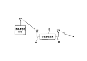
- FIG. 1 is an overall configuration diagram of a mobile communication system according to a first embodiment of the present invention.
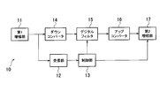
- FIG. 2 is a functional block diagram of the relay amplification device according to the first embodiment of the present invention.
- FIG. 3 is a diagram illustrating an example of broadcast information received by the relay amplification device according to the first embodiment of the present invention.
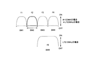
- FIG. 4 is a diagram for explaining how the frequency band to be amplified is appropriately changed in the relay amplifying device according to the first embodiment of the present invention.
- FIG. 5 is a flowchart for explaining the operation of the relay amplifying apparatus according to the first embodiment of the present invention.
- the mobile communication system As shown in FIG. 1, the mobile communication system according to the present embodiment amplifies radio waves received from the radio base station BTS via the first antenna A, and then re-radiates in the downlink via the second antenna B. There is provided a relay amplifying apparatus 10 configured to do so.
- the relay amplification device 10 amplifies radio waves received from the radio base station BTS of a plurality of types of communication methods. Later, it is configured to re-radiate in the downlink.
- W-CDMA mobile communication and LTE (Long Term Evolution) mobile communication are performed.
- LTE Long Term Evolution
- the relay amplifying device 10 includes a first amplifying unit 11, a receiving unit 12, a control unit 13, a down converter 14, a digital filter 15, an up converter 16, And a second amplifying unit 17.
- the first amplifying unit 11 is configured to amplify radio waves (radio signals) received from the radio base station BTS via the first antenna A.
- the down converter 14 is configured to convert the output signal from the first amplifying unit 11 into a baseband signal.
- the digital filter 15 is configured to perform a filtering process on the output signal from the down converter 14.
- the up converter 16 is configured to convert the output signal from the digital filter 15 into a radio signal.
- the second amplification unit 17 is configured to amplify the output signal from the up-converter 16 and re-radiate it in the downlink via the second antenna.
- the receiving unit 12 receives broadcast information included in radio waves (radio signals) received and amplified from the radio base station BTS via the first antenna A in the first amplification unit 11, and the frequency included in the broadcast information
- the range information is configured to be transmitted to the control unit 13.
- the frequency range information includes a combination of “center frequency”, “bandwidth”, “communication method”, and “ON / OFF” for one or a plurality of frequency bands. Including.
- “ON / OFF” is a usage status indicating whether or not the frequency band is in use.
- the frequency range information only needs to include a combination of “center frequency” and “bandwidth” for at least one or a plurality of bands. In other words, the frequency range information may not include “communication method” and “ON / OFF”.
- the frequency range information is not included in the broadcast information and the receiving unit 12 does not transmit the frequency range information to the control unit 13.
- the relay amplification apparatus 10 includes a receiver corresponding to the corresponding communication method, the frequency is changed, and the received cell search is performed. It is possible to recognize whether the bandwidth is in use.
- the frequency band # 2 that is “BW2” is a frequency band for mobile communication of the W-CDMA system, and it can be seen that it is currently in use.
- the frequency band # 3 in which the “center frequency” is “f3” and the “bandwidth” is “BW3” and the “center frequency” is “f4” and the “bandwidth”. It is understood that the frequency band # 4 in which “BW4” is “BW4” is a frequency band for W-CDMA mobile communication and is not currently used.
- the frequency band # 5 in which the “center frequency” is “f5” and the “bandwidth” is “BW5” is a frequency band for LTE mobile communication, You can see that it is not currently used.
- BW1 to “BW4” may be 5 MHz
- BW5 may be 10 MHz
- the receiving unit 12 when the first amplifying unit 11 receives broadcast information from a plurality of neighboring radio base stations BTS, the receiving unit 12 has the smallest propagation loss (path loss) with the relay amplifying device 10. It may be configured to receive only broadcast information transmitted by a certain radio base station BTS.
- the receiving unit 12 uses the downlink common control channel (for example, PCPICH: Physical Common Pilot) in the relay amplifying device 10. It may be configured to receive only broadcast information transmitted by the radio base station BTS having the maximum received power of a signal (for example, pilot signal) received via (Channel).
- PCPICH Physical Common Pilot
- the receiving unit 12 may be configured to periodically receive broadcast information.
- the receiving unit 12 is broadcast information transmitted by a predetermined radio base station BTS in a predetermined communication system (for example, W-CDMA system or LTE system) within a predetermined frequency band (for example, frequency band # 2). May be configured to receive.
- a predetermined radio base station BTS in a predetermined communication system (for example, W-CDMA system or LTE system) within a predetermined frequency band (for example, frequency band # 2). May be configured to receive.
- the receiving unit 12 can receive the LTE frequency band as the frequency range information included in the broadcast information.
- the center frequency (EARFCN) and the bandwidth (Measurement Bandwidth) can be broadcast using SIB19 in BCH (Broadcast Channel) (see 3GPP TS25.331 V8.6.0 SEC. 10.3.7.115). .
- the receiving unit 12 searches for a W-CDMA wireless signal, acquires the center frequency and bandwidth of the wireless signal in use, and acquires frequency range information based on the acquired center frequency and bandwidth. Can do.
- the receiving unit 12 can acquire frequency range information based on the frequency band in which the W-CDMA radio signal can be received and the LTE frequency band included in the broadcast information. That is, the frequency range information included in the broadcast information only needs to include only a communication method (LTE method) other than the communication method (for example, W-CDMA method) that can be received by the receiving unit 12.
- LTE method a communication method
- W-CDMA method a communication method that can be received by the receiving unit 12.
- the receiving unit 12 may receive the frequency range information of both communication methods included in the broadcast information. Good. Even when the receiving unit 12 is a W-CDMA receiver and the frequency range information of different frequencies of the W-CDMA system is not broadcasted by the SIB 11 of the BCH, the frequency range is obtained by searching while switching the frequency that can be received by the receiver Can be specified.
- the control unit 13 is configured to adaptively change the frequency band for amplifying the radio wave based on the broadcast information received by the receiving unit 12 and the frequency range that can be received by searching.
- control unit 13 amplifies the radio wave in the used frequency band based on the frequency range information included in the broadcast information, and lowers the amplification degree for the radio wave in the unused frequency band.
- the frequency band for amplifying radio waves is adaptively changed.
- the control unit 13 when the control unit 13 receives the frequency range information shown in FIG. 3, the control unit 13 amplifies radio waves in the frequency bands # 1, # 2, and # 5 that are in use based on the frequency range information.
- the frequency band for amplifying the radio waves is adaptively changed by lowering the amplification degree for the radio waves in the frequency bands # 3 and # 4.
- control unit 13 is configured to adaptively change the frequency band for amplifying radio waves by changing the waveform of the digital filter 15.
- the control unit 13 passes radio waves in the frequency bands # 1, # 2, and # 5 and passes the frequency bands # 3, # 5 as shown in FIG.
- the digital filter 15 is instructed to perform a filtering process for reducing the transmission rate of the radio wave 4 or blocking the radio waves of the frequency bands # 3 and # 4.
- the digital filter 15 is configured to perform filtering in units of 10 MHz in the frequency band # 5, and is configured to perform filtering in units of 5 MHz in the frequency bands # 1 to # 4. .
- control unit 13 adaptively changes the frequency band for amplifying the radio wave based on the broadcast information transmitted by the radio base station BTS having the smallest propagation loss with the relay amplification device 10. It may be configured.
- control unit 13 broadcasts the radio base station BTS having the maximum received power of a signal (for example, pilot signal) received via the downlink common control channel (for example, PCPICH) in the relay amplifying apparatus 10.
- a signal for example, pilot signal
- PCPICH downlink common control channel
- the frequency band for amplifying radio waves may be adaptively changed based on the information.
- control unit 13 may be configured to change the amplification degree in the second amplification unit 17 based on the minimum value of the propagation loss described above.
- control unit 13 changes the amplification degree in the second amplifying unit 17 so that the power of a signal (for example, a pilot signal) transmitted via the downlink common control channel (for example, PCPICH) becomes a constant value.
- a signal for example, a pilot signal
- PCPICH downlink common control channel
- control unit 13 is configured to amplify the radio wave in the frequency band being used in the downlink and reduce the amplification degree of the radio wave in the unused frequency band in the downlink with respect to the radio wave received via the uplink. It may be.
- control unit 13 may be configured not to amplify radio waves in a frequency band that is not set in the frequency range information described above.
- the relay amplifying apparatus 10 performs a cell search process in step S101, acquires broadcast information in a cell detected by the cell search process in step S102, and includes neighboring cells included in the broadcast information. Get information.
- step S103 the relay amplifying apparatus 10 detects a propagation loss (path loss) in a neighboring cell specified by the obtained neighboring cell information. decide.
- step S105 the relay amplifying apparatus 10 acquires broadcast information transmitted by a radio base station (or cell) with the smallest propagation loss, and acquires frequency range information included in the broadcast information.
- step S106 the relay amplification device 10 adaptively changes the frequency band for amplifying the radio wave based on the frequency range information, that is, determines the pass band of the digital filter 15.
- the relay amplifying apparatus 10 amplifies only radio waves in the used frequency band based on the above-described frequency range information, and uses the unused frequency band. It is possible to operate so as not to amplify the radio wave by judging it as noise.
- the relay amplifying apparatus 10 uses the digital filter 15 in the frequency band near the frequency band operated by itself based on the frequency range information described above. By changing the pass band, the radio waves in these frequency bands can be amplified and re-radiated.
- relaying is performed in an environment where a plurality of types of communication schemes, for example, W-CDMA mobile communication and LTE mobile communication are mixed.
- W-CDMA mobile communication and LTE mobile communication are mixed.
- the amplifying apparatus 10 it is not necessary to provide both the W-CDMA reception unit 12 and the LTE reception unit 12.
- the W-CDMA reception unit 12 uses the W-CDMA mobile communication frequency band (or the LTE mobile communication frequency band) as a radio signal.
- the W-CDMA mobile communication frequency band or the LTE mobile communication frequency band
- Both W-CDMA mobile communication signals and LTE mobile communication signals can be amplified and re-radiated.
- the reception unit 12 may acquire the frequency range information based on the broadcast information. Even in this case, it is not necessary to provide both the W-CDMA receiver 12 and the LTE receiver 12.
- the relay amplification device 10 changes the pass band of the digital filter 15 in consideration of the bandwidth included in the frequency range information described above. Therefore, radio waves in frequency bands with different bandwidths, such as the frequency band of the W-CDMA system and the frequency band of the LTE system, can be accurately re-radiated.
- the relay amplifying apparatus 10 since the relay amplifying apparatus 10 is configured to periodically receive such broadcast information, the frequency range information is changed.
- the pass band of the digital filter 15 can be changed as appropriate.
- the relay amplification device 10 grasps the operation status in the frequency band based on the broadcast information, so that signals of a plurality of systems can be received in the same frequency band.
- the relay amplification device 10 grasps the operation status in the frequency band based on the broadcast information, so that signals of a plurality of systems can be received in the same frequency band.
- the mobile communication system according to the first embodiment of the present invention it is possible to increase the processing speed when realizing this function.
- the relay amplifying apparatus 10 simply determines the frequency band to be amplified only by the reception level, there is a possibility that an error of erroneously amplifying an interference wave or the like may occur. Such a mistake can be avoided if the frequency band to be amplified can be determined.
- the first feature of the present embodiment is a relay amplifying apparatus 10 configured to amplify radio waves received from the radio base station BTS and then re-radiate in the downlink, and is transmitted by the radio base station BTS.
- a receiving unit 12 configured to receive the broadcast information
- a control unit 13 configured to adaptively change a frequency band for amplifying the radio wave based on the broadcast information. Is the gist.
- the frequency range information includes a combination of the center frequency and the bandwidth for one or a plurality of frequency bands
- the control unit 13 includes the frequency range information included in the broadcast information. Is configured to adaptively change the frequency band to amplify the radio wave by amplifying the radio wave in the frequency band in use and lowering the amplification degree for the radio wave in the unused frequency band Also good.
- the frequency range information includes a center frequency, a bandwidth, and a usage status (“ON / OFF”) indicating whether or not the frequency band is in use for one or a plurality of frequency bands.
- the control unit 13 includes a combination, and amplifies the radio wave in the used frequency band based on the frequency range information included in the broadcast information, and lowers the amplification degree for the radio wave in the unused frequency band.
- the frequency band for amplifying radio waves may be adaptively changed.
- the control unit 13 amplifies radio waves based on broadcast information transmitted by the radio base station BTS having the smallest propagation loss (path loss) with the relay amplification device 10.
- the frequency band to be changed may be adaptively changed.
- control unit 13 is based on broadcast information transmitted by the radio base station BTS having the maximum received power of the signal received via the downlink common control channel in the relay amplifying apparatus 10.
- the frequency band for amplifying radio waves may be adaptively changed.
- control unit 13 may be configured to change the amplification degree based on the above-described minimum value of the propagation loss.
- control unit 13 may be configured to adaptively change the frequency band for amplifying radio waves based on the frequency range that the receiving unit 12 can receive.
- control unit 13 is configured to change the amplification degree so that the power of the signal transmitted via the downlink common control channel becomes a constant value. Also good.
- the receiving unit 12 may be configured to periodically receive broadcast information transmitted by the radio base station BTS.
- the control unit 13 amplifies radio waves in the frequency band being used in the downlink for radio waves received via the uplink, and transmits radio waves in the unused frequency band in the downlink. You may be comprised so that amplification degree may be lowered
- control unit 13 is configured to change the amplification degree so that the output of the P-CPICH (specific channel) among the downlink common control channels is constant. Also good.
- the operations of the radio base station BTS and the relay amplifying apparatus 10 described above may be implemented by hardware, may be implemented by a software module executed by a processor, or may be implemented by a combination of both. Good.
- Software modules include RAM (Random Access Memory), flash memory, ROM (Read Only Memory), EPROM (Erasable Programmable ROM), EEPROM (Electronically Erasable and Programmable, Removable ROM, and Hard Disk). Alternatively, it may be provided in an arbitrary format storage medium such as a CD-ROM.
- the storage medium is connected to the processor so that the processor can read and write information from and to the storage medium. Further, such a storage medium may be integrated in the processor. Further, such a storage medium and a processor may be provided in the ASIC. Such an ASIC may be provided in the radio base station BTS and the relay amplification device 10. In addition, the storage medium and the processor may be provided in the radio base station BTS and the relay amplification device 10 as discrete components.
- only a desired radio wave can be amplified and re-radiated without amplifying unused band noise, which is useful in wireless communication and the like.
Landscapes
- Engineering & Computer Science (AREA)
- Computer Networks & Wireless Communication (AREA)
- Signal Processing (AREA)
- Radio Relay Systems (AREA)
- Mobile Radio Communication Systems (AREA)
Abstract
Description
図1乃至図4を参照して、本発明の第1の実施形態に係る移動通信システムの構成について説明する。
以下、図5を参照して、本実施形態に係る移動通信システムの動作、具体的には、本実施形態に係る中継増幅装置10の動作について説明する。
本発明の第1の実施形態に係る移動通信システムによれば、中継増幅装置10が、上述の周波数範囲情報に基づいて、使用中の周波数帯域の電波のみを増幅させ、未使用の周波数帯域の電波を雑音と判断して増幅しないように動作することができる。
11…第1増幅部
12…受信部
13…制御部
14…ダウンコンバータ
15…デジタルフィルタ
16…アップコンバータ
17…第2増幅部
Claims (10)
- 無線基地局から受信した電波を増幅した後、下りリンクにおいて再放射するように構成されている中継増幅装置であって、
無線基地局によって送信されている報知情報を受信するように構成されている受信部と、
前記報知情報に基づいて、前記電波を増幅する周波数帯域を適応的に変化させるように構成されている制御部とを具備し、
前記報知情報に含まれている周波数範囲情報は、1つ又は複数の周波数帯域について、中心周波数と帯域幅との組み合わせを含み、
前記制御部は、前記周波数範囲情報に基づいて、使用中の周波数帯域内の電波を増幅し、未使用の周波数帯域内の電波に対する増幅度を下げることによって、前記電波を増幅する周波数帯域を適応的に変化させるように構成されていることを特徴とする中継増幅装置。 - 前記受信部は、無線基地局によって送信されている報知情報を複数の周波数で受信するように構成され、
前記制御部は、前記受信部で受信可能な周波数に基づいて、使用中の周波数帯域内の電波を増幅し、未使用の周波数帯域内の電波に対する増幅度を下げることによって、前記電波を増幅する周波数帯域を適応的に変化させるように構成されていることを特徴とする請求項1に記載の中継増幅装置。 - 周波数範囲情報は、1つ又は複数の周波数帯域について、中心周波数と帯域幅と使用中であるか否かについて示す使用状況との組み合わせを含み、
前記制御部は、前記報知情報に含まれている周波数範囲情報に基づいて、使用中の周波数帯域内の電波を増幅し、未使用の周波数帯域内の電波に対する増幅度を下げることによって、前記電波を増幅する周波数帯域を適応的に変化させるように構成されていることを特徴とする請求項1に記載の中継増幅装置。 - 前記制御部は、前記中継増幅装置との間の伝搬損が最小である無線基地局によって送信されている報知情報に基づいて、前記電波を増幅する周波数帯域を適応的に変化させるように構成されていることを特徴とする請求項1乃至3の何れか一項に記載の中継増幅装置。
- 前記制御部は、前記中継増幅装置において下り共通制御チャネルを介して受信した信号の受信電力が最大である無線基地局によって送信されている報知情報に基づいて、前記電波を増幅する周波数帯域を適応的に変化させるように構成されていることを特徴とする請求項1乃至3の何れか一項に記載の中継増幅装置。
- 前記制御部は、前記伝搬損の最小値に基づいて、前記増幅度を変化させるように構成されていることを特徴とする請求項4に記載の中継増幅装置。
- 前記制御部は、前記下り共通制御チャネルを介して送信される信号の電力が一定の値になるように、前記増幅度を変化させるように構成されていることを特徴とする請求項5に記載の中継増幅装置。
- 前記受信部は、定期的に、前記無線基地局によって送信されている報知情報を受信するように構成されていることを特徴とする請求項1乃至7のいずれか一項に記載の中継増幅装置。
- 前記制御部は、上りリンクを介して受信した電波について、前記使用中の周波数帯域の電波を増幅し、前記未使用の周波数帯域の電波の増幅度を下げるように構成されていることを特徴とする請求項1に記載の中継増幅装置。
- 前記制御部は、前記下り共通制御チャネルのうち、特定のチャネルの出力が一定となるように、前記増幅度を変化させるように構成されていることを特徴とする請求項5に記載の中継増幅装置。
Priority Applications (4)
| Application Number | Priority Date | Filing Date | Title |
|---|---|---|---|
| EP10786248A EP2442459A1 (en) | 2009-06-12 | 2010-06-11 | Relay amplification apparatus |
| US13/377,713 US20120164939A1 (en) | 2009-06-12 | 2010-06-11 | Repeater equipment |
| CN2010800259942A CN102804635A (zh) | 2009-06-12 | 2010-06-11 | 中继放大装置 |
| JP2011518587A JP5328913B2 (ja) | 2009-06-12 | 2010-06-11 | 中継増幅装置 |
Applications Claiming Priority (2)
| Application Number | Priority Date | Filing Date | Title |
|---|---|---|---|
| JP2009-141487 | 2009-06-12 | ||
| JP2009141487 | 2009-06-12 |
Publications (1)
| Publication Number | Publication Date |
|---|---|
| WO2010143717A1 true WO2010143717A1 (ja) | 2010-12-16 |
Family
ID=43308972
Family Applications (1)
| Application Number | Title | Priority Date | Filing Date |
|---|---|---|---|
| PCT/JP2010/059958 Ceased WO2010143717A1 (ja) | 2009-06-12 | 2010-06-11 | 中継増幅装置 |
Country Status (6)
| Country | Link |
|---|---|
| US (1) | US20120164939A1 (ja) |
| EP (1) | EP2442459A1 (ja) |
| JP (1) | JP5328913B2 (ja) |
| KR (1) | KR20120027356A (ja) |
| CN (1) | CN102804635A (ja) |
| WO (1) | WO2010143717A1 (ja) |
Cited By (1)
| Publication number | Priority date | Publication date | Assignee | Title |
|---|---|---|---|---|
| JP2013115483A (ja) * | 2011-11-25 | 2013-06-10 | Hitachi Kokusai Electric Inc | 中継増幅装置及び中継方法 |
Families Citing this family (4)
| Publication number | Priority date | Publication date | Assignee | Title |
|---|---|---|---|---|
| KR20140090533A (ko) * | 2012-12-20 | 2014-07-17 | 삼성전자주식회사 | 이동통신시스템에서의 신호 송신장치 및 방법 |
| US20150072685A1 (en) * | 2013-09-10 | 2015-03-12 | Acer Incorporated | Method of performing cell reselection in wireless communication system having multiple types of networks |
| CN110224735B (zh) * | 2019-05-13 | 2021-05-11 | 中国联合网络通信集团有限公司 | 一种无线中继方法及设备 |
| US11611391B1 (en) * | 2021-02-19 | 2023-03-21 | Mission Microwave Technologies, Llc | Satellite communications solid-state block upconverter with gain compensation |
Citations (6)
| Publication number | Priority date | Publication date | Assignee | Title |
|---|---|---|---|---|
| JPH11112399A (ja) * | 1997-09-29 | 1999-04-23 | Ntt Mobil Commun Network Inc | 移動通信の周波数選択形中継方法及び装置 |
| JP2005278164A (ja) * | 2004-02-25 | 2005-10-06 | Fujitsu Ltd | 中継器 |
| WO2006126344A1 (ja) * | 2005-05-25 | 2006-11-30 | Hitachi Kokusai Electric Inc. | 無線中継装置 |
| JP2007189306A (ja) * | 2006-01-11 | 2007-07-26 | Nippon Telegr & Teleph Corp <Ntt> | 無線通信装置及び無線通信システム |
| JP2009100458A (ja) * | 2007-09-26 | 2009-05-07 | Hitachi Kokusai Electric Inc | 無線中継増幅装置 |
| JP2009141487A (ja) | 2007-12-04 | 2009-06-25 | Ricoh Co Ltd | デジタル複写機 |
Family Cites Families (12)
| Publication number | Priority date | Publication date | Assignee | Title |
|---|---|---|---|---|
| JPS61148926A (ja) * | 1984-12-24 | 1986-07-07 | Kokusai Denshin Denwa Co Ltd <Kdd> | 通信衛星中継器 |
| SE502811C2 (sv) * | 1994-05-11 | 1996-01-22 | Allgon Ab | Repeater |
| SE510569C2 (sv) * | 1996-05-31 | 1999-06-07 | Allgon Ab | Repeterare med variabel bandbredd |
| US7460831B2 (en) * | 2002-06-20 | 2008-12-02 | Dekolink Wireless Ltd. | System and method for excluding narrow band noise from a communication channel |
| US20040156097A1 (en) * | 2003-02-06 | 2004-08-12 | Spotwave Wireless Inc. | Intelligent gain control in an on-frequency repeater |
| US7299005B1 (en) * | 2004-01-07 | 2007-11-20 | Sprint Spectrum L.P. | Radio frequency repeater with automated block/channel selection |
| US7480485B1 (en) * | 2004-01-07 | 2009-01-20 | Sprint Spectrum L.P. | Radio frequency repeater with automated block/channel selection |
| US7170344B2 (en) * | 2004-02-03 | 2007-01-30 | Ntt Docomo, Inc. | Multi-band predistorter using power series representation |
| US7778596B2 (en) * | 2004-07-29 | 2010-08-17 | Qualcomm Incorporated | Airlink sensing watermarking repeater |
| JPWO2006043592A1 (ja) * | 2004-10-20 | 2008-05-22 | 松下電器産業株式会社 | ブースタ |
| JP4344367B2 (ja) * | 2005-06-06 | 2009-10-14 | 株式会社エヌ・ティ・ティ・ドコモ | 多周波帯用べき級数型プリディストータ |
| US7957693B2 (en) * | 2007-09-26 | 2011-06-07 | Hitachi Kokusai Electric Inc. | Wireless relay amplification apparatus |
-
2010
- 2010-06-11 JP JP2011518587A patent/JP5328913B2/ja not_active Expired - Fee Related
- 2010-06-11 EP EP10786248A patent/EP2442459A1/en not_active Withdrawn
- 2010-06-11 KR KR1020117030035A patent/KR20120027356A/ko not_active Ceased
- 2010-06-11 CN CN2010800259942A patent/CN102804635A/zh active Pending
- 2010-06-11 US US13/377,713 patent/US20120164939A1/en not_active Abandoned
- 2010-06-11 WO PCT/JP2010/059958 patent/WO2010143717A1/ja not_active Ceased
Patent Citations (6)
| Publication number | Priority date | Publication date | Assignee | Title |
|---|---|---|---|---|
| JPH11112399A (ja) * | 1997-09-29 | 1999-04-23 | Ntt Mobil Commun Network Inc | 移動通信の周波数選択形中継方法及び装置 |
| JP2005278164A (ja) * | 2004-02-25 | 2005-10-06 | Fujitsu Ltd | 中継器 |
| WO2006126344A1 (ja) * | 2005-05-25 | 2006-11-30 | Hitachi Kokusai Electric Inc. | 無線中継装置 |
| JP2007189306A (ja) * | 2006-01-11 | 2007-07-26 | Nippon Telegr & Teleph Corp <Ntt> | 無線通信装置及び無線通信システム |
| JP2009100458A (ja) * | 2007-09-26 | 2009-05-07 | Hitachi Kokusai Electric Inc | 無線中継増幅装置 |
| JP2009141487A (ja) | 2007-12-04 | 2009-06-25 | Ricoh Co Ltd | デジタル複写機 |
Non-Patent Citations (1)
| Title |
|---|
| "IEEE 19th International Symposium on Personal, Indoor and Mobile Radio Communications, 2008. PIMRC 2008.", 15 September 2008, article RALF IRMER ET AL.: "On coverage and capacity of relaying in LTE-advanced in example deployments", pages: 1 - 5, XP008148607 * |
Cited By (1)
| Publication number | Priority date | Publication date | Assignee | Title |
|---|---|---|---|---|
| JP2013115483A (ja) * | 2011-11-25 | 2013-06-10 | Hitachi Kokusai Electric Inc | 中継増幅装置及び中継方法 |
Also Published As
| Publication number | Publication date |
|---|---|
| KR20120027356A (ko) | 2012-03-21 |
| US20120164939A1 (en) | 2012-06-28 |
| JP5328913B2 (ja) | 2013-10-30 |
| CN102804635A (zh) | 2012-11-28 |
| EP2442459A1 (en) | 2012-04-18 |
| JPWO2010143717A1 (ja) | 2012-11-29 |
Similar Documents
| Publication | Publication Date | Title |
|---|---|---|
| US11742931B2 (en) | Time division duplex (TDD) network protection repeater | |
| US8559869B2 (en) | Smart channel selective repeater | |
| EP1298806B2 (en) | LNA gain adjustment in an RF receiver to compensate for intermodulation interference | |
| US10225845B2 (en) | Channelization for signal boosters | |
| US7120410B2 (en) | LNA gain adjustment in an RF receiver to compensate for intermodulation interference | |
| JP4851641B2 (ja) | 受信機のための自動利得制御およびその方法 | |
| US20140177483A1 (en) | Reducing interference in a wireless network | |
| JP5328913B2 (ja) | 中継増幅装置 | |
| CN105657786B (zh) | 用户设备和低噪声放大器的调整增益的方法 | |
| CN105379130B (zh) | 与无线电信号的接收有关的方法和设备 | |
| EP3202199B1 (en) | Determining a centre frequency in an unlicensed frequency band to use | |
| JP2017135620A (ja) | 通信中継装置、通信中継システム、方法及びプログラム | |
| EP2395788A1 (en) | Wireless communication system and base station | |
| US20100267351A1 (en) | Receiver and gain control method | |
| KR20010050670A (ko) | 수신기의 다이나믹 랜지 경감을 위해 파워에 근거한 동적채널 할당을 위한 방법 및 장치 | |
| JP2018011137A (ja) | 通信中継装置、通信中継システム、方法及びプログラム | |
| KR101514986B1 (ko) | 에너지 분산 소비형 하이브리드 무선통신 중계기 | |
| JP2006054601A (ja) | 無線通信システム | |
| KR20130010578A (ko) | 듀얼 밴드 통신 방식이 적용된 복수의 무선통신 칩에서 동시에 신호를 전송하기 위한 단말 장치 및 그 단말 장치의 듀얼 밴드 전송 방법 | |
| CN103582106A (zh) | 基于双载波跳频技术的信号处理方法、装置及塔顶放大器 | |
| JP5213628B2 (ja) | 中継送受信装置 | |
| KR20080071306A (ko) | 휴대용 단말기의 무선 송수신 장치 |
Legal Events
| Date | Code | Title | Description |
|---|---|---|---|
| WWE | Wipo information: entry into national phase |
Ref document number: 201080025994.2 Country of ref document: CN |
|
| 121 | Ep: the epo has been informed by wipo that ep was designated in this application |
Ref document number: 10786248 Country of ref document: EP Kind code of ref document: A1 |
|
| NENP | Non-entry into the national phase |
Ref country code: DE |
|
| WWE | Wipo information: entry into national phase |
Ref document number: 2011518587 Country of ref document: JP |
|
| ENP | Entry into the national phase |
Ref document number: 20117030035 Country of ref document: KR Kind code of ref document: A |
|
| WWE | Wipo information: entry into national phase |
Ref document number: 2010786248 Country of ref document: EP |
|
| WWE | Wipo information: entry into national phase |
Ref document number: 13377713 Country of ref document: US |