WO2010143704A1 - 分流器及びこの分流器を備えた膨張弁並びにこの膨張弁を備えた冷凍装置 - Google Patents
分流器及びこの分流器を備えた膨張弁並びにこの膨張弁を備えた冷凍装置 Download PDFInfo
- Publication number
- WO2010143704A1 WO2010143704A1 PCT/JP2010/059902 JP2010059902W WO2010143704A1 WO 2010143704 A1 WO2010143704 A1 WO 2010143704A1 JP 2010059902 W JP2010059902 W JP 2010059902W WO 2010143704 A1 WO2010143704 A1 WO 2010143704A1
- Authority
- WO
- WIPO (PCT)
- Prior art keywords
- chamber
- refrigerant
- flow
- shunt
- speed increasing
- Prior art date
- Legal status (The legal status is an assumption and is not a legal conclusion. Google has not performed a legal analysis and makes no representation as to the accuracy of the status listed.)
- Ceased
Links
Images









Classifications
-
- F—MECHANICAL ENGINEERING; LIGHTING; HEATING; WEAPONS; BLASTING
- F25—REFRIGERATION OR COOLING; COMBINED HEATING AND REFRIGERATION SYSTEMS; HEAT PUMP SYSTEMS; MANUFACTURE OR STORAGE OF ICE; LIQUEFACTION SOLIDIFICATION OF GASES
- F25B—REFRIGERATION MACHINES, PLANTS OR SYSTEMS; COMBINED HEATING AND REFRIGERATION SYSTEMS; HEAT PUMP SYSTEMS
- F25B39/00—Evaporators; Condensers
- F25B39/02—Evaporators
- F25B39/028—Evaporators having distributing means
-
- F—MECHANICAL ENGINEERING; LIGHTING; HEATING; WEAPONS; BLASTING
- F25—REFRIGERATION OR COOLING; COMBINED HEATING AND REFRIGERATION SYSTEMS; HEAT PUMP SYSTEMS; MANUFACTURE OR STORAGE OF ICE; LIQUEFACTION SOLIDIFICATION OF GASES
- F25B—REFRIGERATION MACHINES, PLANTS OR SYSTEMS; COMBINED HEATING AND REFRIGERATION SYSTEMS; HEAT PUMP SYSTEMS
- F25B41/00—Fluid-circulation arrangements
-
- F—MECHANICAL ENGINEERING; LIGHTING; HEATING; WEAPONS; BLASTING
- F25—REFRIGERATION OR COOLING; COMBINED HEATING AND REFRIGERATION SYSTEMS; HEAT PUMP SYSTEMS; MANUFACTURE OR STORAGE OF ICE; LIQUEFACTION SOLIDIFICATION OF GASES
- F25B—REFRIGERATION MACHINES, PLANTS OR SYSTEMS; COMBINED HEATING AND REFRIGERATION SYSTEMS; HEAT PUMP SYSTEMS
- F25B41/00—Fluid-circulation arrangements
- F25B41/30—Expansion means; Dispositions thereof
- F25B41/31—Expansion valves
-
- F—MECHANICAL ENGINEERING; LIGHTING; HEATING; WEAPONS; BLASTING
- F25—REFRIGERATION OR COOLING; COMBINED HEATING AND REFRIGERATION SYSTEMS; HEAT PUMP SYSTEMS; MANUFACTURE OR STORAGE OF ICE; LIQUEFACTION SOLIDIFICATION OF GASES
- F25B—REFRIGERATION MACHINES, PLANTS OR SYSTEMS; COMBINED HEATING AND REFRIGERATION SYSTEMS; HEAT PUMP SYSTEMS
- F25B41/00—Fluid-circulation arrangements
- F25B41/40—Fluid line arrangements
- F25B41/42—Arrangements for diverging or converging flows, e.g. branch lines or junctions
- F25B41/45—Arrangements for diverging or converging flows, e.g. branch lines or junctions for flow control on the upstream side of the diverging point, e.g. with spiral structure for generating turbulence
-
- F—MECHANICAL ENGINEERING; LIGHTING; HEATING; WEAPONS; BLASTING
- F28—HEAT EXCHANGE IN GENERAL
- F28F—DETAILS OF HEAT-EXCHANGE AND HEAT-TRANSFER APPARATUS, OF GENERAL APPLICATION
- F28F9/00—Casings; Header boxes; Auxiliary supports for elements; Auxiliary members within casings
- F28F9/02—Header boxes; End plates
- F28F9/026—Header boxes; End plates with static flow control means, e.g. with means for uniformly distributing heat exchange media into conduits
- F28F9/0263—Header boxes; End plates with static flow control means, e.g. with means for uniformly distributing heat exchange media into conduits by varying the geometry or cross-section of header box
-
- F—MECHANICAL ENGINEERING; LIGHTING; HEATING; WEAPONS; BLASTING
- F25—REFRIGERATION OR COOLING; COMBINED HEATING AND REFRIGERATION SYSTEMS; HEAT PUMP SYSTEMS; MANUFACTURE OR STORAGE OF ICE; LIQUEFACTION SOLIDIFICATION OF GASES
- F25B—REFRIGERATION MACHINES, PLANTS OR SYSTEMS; COMBINED HEATING AND REFRIGERATION SYSTEMS; HEAT PUMP SYSTEMS
- F25B13/00—Compression machines, plants or systems, with reversible cycle
-
- F—MECHANICAL ENGINEERING; LIGHTING; HEATING; WEAPONS; BLASTING
- F25—REFRIGERATION OR COOLING; COMBINED HEATING AND REFRIGERATION SYSTEMS; HEAT PUMP SYSTEMS; MANUFACTURE OR STORAGE OF ICE; LIQUEFACTION SOLIDIFICATION OF GASES
- F25B—REFRIGERATION MACHINES, PLANTS OR SYSTEMS; COMBINED HEATING AND REFRIGERATION SYSTEMS; HEAT PUMP SYSTEMS
- F25B2400/00—Component parts or details not otherwise provided for in this subclass
- F25B2400/02—Centrifugal separation of gas, liquid or oil
-
- F—MECHANICAL ENGINEERING; LIGHTING; HEATING; WEAPONS; BLASTING
- F25—REFRIGERATION OR COOLING; COMBINED HEATING AND REFRIGERATION SYSTEMS; HEAT PUMP SYSTEMS; MANUFACTURE OR STORAGE OF ICE; LIQUEFACTION SOLIDIFICATION OF GASES
- F25B—REFRIGERATION MACHINES, PLANTS OR SYSTEMS; COMBINED HEATING AND REFRIGERATION SYSTEMS; HEAT PUMP SYSTEMS
- F25B2500/00—Problems to be solved
- F25B2500/01—Geometry problems, e.g. for reducing size
Definitions
- the present invention provides a flow divider main body having a flow dividing chamber in which a refrigerant flows, a refrigerant inlet provided in the flow divider main body, and a refrigerant flowing into the flow dividing chamber through the refrigerant inlet.
- the present invention relates to a flow divider comprising a flow dividing pipe connection port to which the flow dividing pipe is connected.
- a configuration is known in which refrigerant flows into a flow dividing chamber provided in the flow divider, and the refrigerant is divided into each flow dividing tube by a plurality of flow dividing tubes connected to the flow dividing chamber.
- a flow divider for example, in the flow divider (refrigerant branch pipe) described in Patent Document 1, the refrigerant that has flowed into the common pipe through the expansion valve is configured to be branched by the branch pipe.
- a branch pipe is provided at a position before the slag flow and the plug flow are formed by the refrigerant, thereby achieving a uniform distribution of the refrigerant.
- the present applicant provides a swirl flow forming chamber in the shunt flow chamber and swirls the refrigerant in the swirl flow formation chamber, thereby suppressing the above-described influence on the refrigerant by the expansion valve and supplying the refrigerant to the shunt tube.
- the structure which performs is proposed (for example, refer patent document 2).
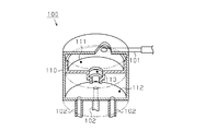
- the configuration of the above-described conventional shunt will be described with reference to FIG.
- the flow divider 100 is connected to the swirl flow forming chamber 111, which is a substantially cylindrical space in which the connection pipe 101 is connected, in the cylindrical flow divider main body 110, and each flow dividing pipe 102.
- a spray chamber 112 which is a substantially cylindrical space.
- a communication chamber 113 which is a substantially cylindrical space that connects the swirl flow forming chamber 111 and the spray chamber 112 to each other is provided.
- the communication chamber 113 is formed with a smaller diameter than the swirl flow forming chamber 111 and the spray chamber 112.
- the communication chamber 113 serves as an orifice.
- the refrigerant ejected from the connection pipe 101 flows into the communication chamber 113 after being given a swirling component in the swirling flow forming chamber 111.
- the refrigerant flowing into the spray chamber 112 from the communication chamber 113 is distributed to each branch pipe 102.
- liquid-rich refrigerant a refrigerant having a higher liquid ratio than gas
- gas-rich refrigerants refrigerants having a higher gas ratio than liquid
- the swirling center of the swirling flow of the refrigerant in the swirling flow forming chamber 111 and the center of the communication chamber 113 do not necessarily coincide with each other, the refrigerant passing through the communication chamber 113 is in a predetermined direction in the communication chamber 113. There may be a case where an uneven swirl flow is formed. As a result, the swirling flow of the refrigerant flowing from the communication chamber 113 to the spray chamber 112 becomes unstable. Therefore, it becomes difficult to achieve a uniform ratio between the refrigerant gas and the liquid flowing through each branch pipe 102 and the distribution amount of the refrigerant, and there is still room for improvement.
- An object of the present invention is to provide a flow divider for achieving a uniform gas-liquid ratio and distribution amount of refrigerant flowing through each flow dividing pipe, an expansion valve provided with the flow divider, and a refrigeration apparatus provided with the expansion valve. is there.
- a flow divider main body having a flow dividing chamber in which a refrigerant flows and a refrigerant inlet provided in the flow divider main body And a shunt pipe connection port to which a shunt pipe for shunting and flowing out the refrigerant that has flowed into the shunt chamber through the refrigerant inlet port is connected, wherein the shunt chamber is the refrigerant inlet port
- the swirling flow forming chamber in which the refrigerant flowing from the swirling flow forms a swirling flow forming chamber, the speed increasing chamber for increasing the swirling speed of the refrigerant flowing out from the swirling forming chamber, and the refrigerant flowing out from the speed increasing chamber diffuse in the form of a mist
- the spray chamber is provided with a spray chamber, and the spray chamber is connected to the branch pipe connection port.
- the refrigerant since the refrigerant has a uniform gas-liquid ratio in the spray chamber, the refrigerant with the uniform gas-liquid ratio is uniformly supplied to each branch pipe connection port. Will be able to.
- the speed increasing chamber is formed in a substantially conical shape in which the inner diameter of the speed increasing chamber becomes smaller toward the spray chamber.
- the speed increasing chamber is formed in a substantially conical shape in which the inner diameter of the speed increasing chamber decreases toward the spray chamber, the swirling diameter of the refrigerant flowing through the speed increasing chamber increases toward the spray chamber. It becomes small and it becomes possible to increase the swirling flow velocity of the refrigerant. As a result, the swirling flow of the refrigerant is stabilized, so that the refrigerant density in the circular cross-sectional flow path in the speed increasing chamber is distributed in circular contour lines having the same center as that of the speed increasing chamber.
- the said spray chamber has a cross-sectional area larger than the area of the exit of the said acceleration chamber.
- the cross-sectional area of the spray chamber is formed to be larger than the area of the outlet of the speed increasing chamber, the two-phase flow composed of gas and liquid as the refrigerant flows into the flow divider.
- a two-phase flow composed of a gas and a liquid having components is stirred in the spray chamber. Therefore, since the refrigerant can be stirred only by the shape of the flow distributor main body, a special instrument or the like for the refrigerant can be omitted. Therefore, the configuration for stirring the refrigerant in the flow divider can be simplified.
- the shunt main body portion includes a peripheral wall portion that forms the swirl forming chamber, and the peripheral wall portion includes a curved surface portion that imparts a swirling component to the refrigerant flowing from the refrigerant inlet port, and the refrigerant inlet port Is preferably provided along the tangential direction of the curved surface portion.
- the refrigerant introduction port is provided along the tangential direction of the curved surface portion of the peripheral wall portion, the refrigerant flowing from the refrigerant introduction port into the swirl forming chamber flows along the curved surface portion. Will be granted. Therefore, when the refrigerant flows into the speed increasing chamber from the swirl forming chamber, the refrigerant has a swirling component in advance, so that the refrigerant easily turns in the speed increasing chamber.
- the said surrounding wall part is provided with the guide part which guides a refrigerant
- the refrigerant flowing from the refrigerant introduction port into the swirl forming chamber collides with the guide portion, so that the refrigerant flows while changing its direction toward the speed increasing chamber. Accordingly, a swirling flow in which the refrigerant flowing from the refrigerant introduction port into the swirl forming chamber efficiently moves toward the speed increasing chamber is formed.
- the refrigerant pipe connected to the refrigerant introduction port is disposed outside the swirl forming chamber so that the amount of eccentricity from the central axis of the swirl forming chamber increases. Without increasing the diameter of the swirl flow forming chamber, only the amount of eccentricity of the inflow portion can be increased, so that the influence of the flow to the center portion can be reduced, and the refrigerant has a center close to the central axis of the branch chamber. It becomes easy to form the swirl flow.
- the flow dividing chamber is connected to the speed increasing chamber between the speed increasing chamber and the swirl forming chamber, and includes an expansion space having an inner diameter larger than the inner diameter of the speed increasing chamber. preferable.
- the expansion space is provided between the speed increasing chamber and the swirl forming chamber, the refrigerant flowing into the speed increasing chamber from the refrigerant introduction port stays in the expansion space. For this reason, the refrigerant provided with the swirl component in the swirl forming chamber swirls even in the enlarged space. Thereby, the swirl component of the refrigerant can be improved.
- the swirl forming chamber and the speed increasing chamber are connected to each other, and the swirl forming chamber is formed in a substantially conical shape or a substantially cylindrical shape whose diameter increases toward the speed increasing chamber.
- the inner diameter of the chamber is preferably formed larger than the inner diameter of the inlet of the speed increasing chamber.
- the flow dividing chamber has a connection space between the speed increasing chamber and the spraying chamber. According to this configuration, when the refrigerant from the speed increasing chamber flows into the connection space, the swirling component of the refrigerant flowing into the spray chamber is not easily affected by the fluctuation of the refrigerant at the refrigerant inlet, and the refrigerant is stabilized. It becomes like this. As a result, the turning of the refrigerant flowing into the spray chamber from the connection space in the spray chamber is stabilized.
- connection space is formed in a space having a constant inner diameter, or has a substantially conical diameter expansion chamber that expands toward the spray chamber at least on the spray chamber side.
- connection space when the connection space is formed in a space having a constant inner diameter, the swirling flow of the refrigerant is further stabilized by the space having the constant inner diameter.
- connection space has a substantially conical diameter-expanding chamber that increases in diameter toward the spray chamber, at least on the spray chamber side, the refrigerant flowing into the spray chamber is expanded in diameter without being abruptly disturbed. It turns and flows along the room. Therefore, the refrigerant can smoothly flow from the speed increasing chamber to the spraying chamber.
- the branch pipe connection ports are annularly arranged along the circumferential direction of the branch chamber, and an inner diameter of a circle formed by connecting inner edges of the arranged branch pipe connection ports is the speed increasing It is preferably larger than the inner diameter of the chamber outlet.
- the refrigerant from the outlet of the speed increasing chamber is It becomes possible to avoid directly colliding with the shunt pipe connection port. Therefore, although a refrigerant
- an expansion valve used in combination with a flow divider is provided. According to this configuration, even if the refrigerant flowing through the diverter through the expansion valve becomes a flow type having a discontinuity such as a slag flow by using the diverter of the present invention in combination with the expansion valve, -It is possible to make uniform the supply of the refrigerant having a uniform liquid ratio to the respective branch pipe connection ports.
- the expansion valve and the flow divider are preferably formed as an integrated structure. According to this configuration, when the expansion valve and the flow divider are provided separately, connection piping for connecting the expansion valve and the flow divider is required. In that respect, in the present invention, since the expansion valve and the flow divider are formed as an integrated structure, the connection pipe can be omitted, and the expansion valve can be made compact. Further, the jet energy from the expansion valve can be effectively used as the flow energy for forming the swirl flow.
- the expansion valve includes a throttle portion that is formed between the valve body and the valve hole and performs a throttle action, and the throttle portion is configured to have a variable opening degree corresponding to a refrigeration load.
- the throttle unit since the throttle unit is configured to have a variable opening degree corresponding to the refrigeration load, the throttle unit can variably adjust the refrigerant flow rate with respect to the refrigeration load.
- the throttle unit compared with the configuration of the throttle section in which the aperture of the throttle section is formed constant, it is possible to obtain an appropriate throttle degree (opening) according to the operating conditions such as the flow rate and the dryness, and the flow of refrigerant Characteristics can be improved.
- a refrigeration apparatus using the expansion valve is provided. According to this configuration, by using the expansion valve of the present invention in the refrigeration apparatus, a refrigeration apparatus that can achieve uniform supply of a refrigerant with a uniform gas-liquid ratio to each branch pipe connection port is provided. can do.
- a flow divider for achieving a uniform gas-liquid ratio and distribution amount of refrigerant flowing through each flow dividing pipe, an expansion valve provided with the flow divider, and a refrigeration apparatus provided with the expansion valve. it can.
- the circuit diagram which shows the refrigerant circuit of the freezing apparatus provided with the flow divider which concerns on one Embodiment of this invention.
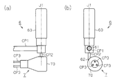
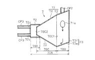
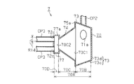
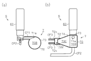
- the expansion valve provided with the flow divider of the embodiment (a) The front view which shows the front structure of the expansion valve, (b) The side view which shows the side structure of the expansion valve.
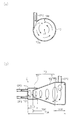
- a partial cross-sectional view showing a partial cross-sectional structure of the expansion valve, (b) an enlarged structure near the valve body of the expansion valve in a state where the valve body is closed The enlarged view and (c) The enlarged view which shows the enlarged structure of the valve body vicinity of the expansion valve of the state which the valve body has opened.
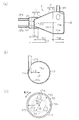
- Sectional drawing which shows the cross-section which cut
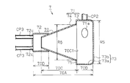
- Sectional drawing which shows the cross-sectional structure which cut
- Sectional drawing which shows the cross-section which cut
- Sectional drawing which shows the cross-section which cut
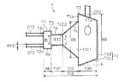
- Sectional drawing which shows the cross-section which cut
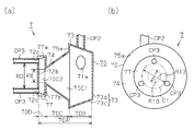
- About 8th Embodiment which actualized the shunt of this invention (a) Sectional drawing which shows the cross-section which cut the same shunt by the plane containing the center axis
- Sectional drawing which shows the cross-section which cut
- Sectional drawing which shows the cross-section which cut
- Sectional drawing which shows the cross-sectional structure which cut
- Sectional drawing which shows the cross-section which cut
- Sectional drawing which shows the cross-sectional structure which cut the same shunt by the plane containing the center axis
- Sectional drawing which shows the cross-sectional structure which cut the same shunt by the plane containing the center axis
- Sectional drawing which shows the cross-sectional structure which cut the same shunt by the plane containing the center axis
- Sectional drawing which shows the cross-section which cut the same shunt by the plane containing the center axis
- the side view which shows the side structure of the same shunt about other embodiment of the shunt of this invention. Sectional drawing which shows the cross-section of the same shunt about the conventional shunt.
- the circuit configuration of the refrigerant circuit diagram of the refrigeration apparatus and the operation of the refrigeration apparatus will be described with reference to FIG.
- the solid line arrow in a figure shows the flow of the refrigerant
- the broken line arrow shows the flow of the refrigerant
- an indoor heat exchanger 2 As shown in FIG. 1, in the refrigeration apparatus 1, an indoor heat exchanger 2, an outdoor heat exchanger 3, an indoor expansion valve 4, an indoor shunt 5, an outdoor expansion valve 6, an outdoor shunt 7,
- a refrigerant circuit is configured by connecting each of the four-way switching valve 8 and the compressor 9 by refrigerant piping.
- the compressor 9 is connected to the indoor heat exchanger 2 and the outdoor heat exchanger 3 via the four-way switching valve 8.
- An indoor side expansion valve 4 is connected to the indoor side heat exchanger 2 via an indoor side flow divider 5.
- An outdoor expansion valve 6 is connected to the outdoor heat exchanger 3 via an outdoor flow divider 7.
- the indoor expansion valve 4 and the outdoor expansion valve 6 are connected to each other.
- the operation of the refrigeration apparatus 1 is roughly divided into a cooling operation and a heating operation.
- the four-way switching valve 8 is switched to the flow path indicated by the broken line in the figure.
- the refrigerant discharged from the compressor 9 is a flow path indicated by a broken line of the four-way switching valve 8, the outdoor heat exchanger 3, the outdoor shunt 7, the outdoor expansion valve 6, It circulates through the flow path shown with the broken line of the indoor side expansion valve 4, the indoor side flow divider 5, the indoor side heat exchanger 2, and the four-way switching valve 8, and is sucked into the compressor 9.
- the outdoor heat exchanger 3 operates as a condenser, and the indoor heat exchanger 2 operates as an evaporator.
- the refrigerant dissipates heat to the outdoor air as the refrigerant exchanges heat with the outdoor air and condenses.
- the indoor heat exchanger 2 the refrigerant is cooled by exchanging heat with the room air and evaporating, whereby the room air is cooled by being absorbed by the refrigerant.
- the four-way switching valve 8 is switched to the flow path indicated by the solid line in the figure.
- the refrigerant discharged from the compressor 9 is a flow path indicated by a solid line of the four-way switching valve 8, the indoor heat exchanger 2, the indoor shunt 5, the indoor expansion valve 4,
- the outdoor expansion valve 6, the outdoor flow divider 7, the outdoor heat exchanger 3, and the four-way switching valve 8 circulate through the flow paths indicated by solid lines and are sucked into the compressor 9.
- the indoor heat exchanger 2 operates as a condenser
- the outdoor heat exchanger 3 operates as an evaporator.
- the refrigerant radiates heat to the room air by performing heat exchange with the room air and condensing.
- the refrigerant absorbs heat from the outdoor air by evaporating by exchanging heat with the outdoor air.
- the indoor expansion valve 4 and the indoor flow divider 5 and the outdoor expansion valve 6 and the outdoor flow divider 7 are used as an expansion valve and a flow divider for both cooling and heating that can reversibly flow the refrigerant, respectively. Become.
- the configuration of the expansion valve mounted on the refrigeration apparatus 1 will be described with reference to FIGS.
- the configurations of the indoor side expansion valve 4 and the outdoor side expansion valve 6 are substantially the same, and the configurations of the indoor side flow divider 5 and the outdoor side flow divider 7 are substantially the same. Therefore, in the following description, the configuration of the outdoor expansion valve 6 and the outdoor flow divider 7 will be described, and the description of the indoor flow divider 5 and the indoor expansion valve 4 will be omitted.
- the expansion valve can be used by circulating refrigerant in the reverse direction.
- the expansion valve is used for the reverse flow when the cooling operation of the refrigeration apparatus is the forward flow, that is, for the heating operation. Is possible.
- the refrigerant is circulated in the forward direction, and the description will be simplified.
- the outdoor expansion valve 6 (hereinafter referred to as “expansion valve 6”) is formed in a substantially cylindrical shape that constitutes the outer frame of the expansion valve 6 and has the central axis J1 in the vertical direction.
- a valve main body 60 is provided.
- the valve body 60 includes a first pipe mounting hole 61 (see FIG. 2B) to which a refrigerant pipe CP1 connected to the indoor expansion valve 4 is mounted, and an outdoor flow divider 7 (hereinafter referred to as “flow divider 7”). )) Is connected to the second pipe attachment hole 62 (see FIG. 3A) to which the refrigerant pipe CP2 is attached.
- a valve chamber 60A which is a cylindrical space coaxial with the central axis J1, is formed inside the valve main body 60.
- the valve chamber 60A communicates with the refrigerant pipe CP1 via the first pipe attachment hole 61 and communicates with the refrigerant pipe CP2 via the second pipe attachment hole 62.
- the valve body 60 has a valve hole 60B that is a cylindrical space that is formed between the second pipe mounting hole 62 and the valve chamber 60A and communicates with each other.
- the valve hole 60 ⁇ / b> B is formed by a wall portion 63 that serves as a valve seat of the valve body 60.
- a valve rod 64 is accommodated in the valve chamber 60A.
- the valve stem 64 extends downward from an upper valve driving device (not shown), and is arranged coaxially with the central axis J1.
- a valve body 65 is provided at the tip of the valve stem 64. And the valve body 65 is comprised so that it can move forward / backward with respect to the valve hole 60B via the valve rod 64 by the drive of a valve drive device.
- the valve body 65 and the valve hole 60B form a throttle portion 60C whose opening degree is variable and can be fully closed in accordance with the refrigeration load (see FIG. 3C). Note that FIG. 3B shows the throttle unit 60C in a fully closed state.
- the expansion valve 6 when a single-phase refrigerant composed of high-pressure liquid or a two-phase refrigerant composed of gas and liquid enters the valve chamber 60A from the refrigerant pipe CP1, the refrigerant is decompressed in the throttle section 60C. Is done.
- the refrigerant depressurized in the throttle unit 60C is a low-pressure two-phase flow and is jetted from the throttle unit 60C toward the refrigerant pipe CP2 in a sprayed state.
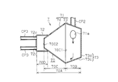
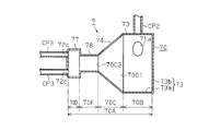
- the flow divider 7 is provided in such a manner that one refrigerant pipe CP2 and a plurality of flow dividing pipes CP3 are respectively attached to a flow divider body 70 having a substantially conical shape centered on the central axis J2. ing. Inside the flow divider main body 70, a flow dividing chamber 70A, which is a space for communicating the refrigerant pipe CP2 and the flow dividing pipe CP3, is formed.
- the shunt main body 70 is integrally formed by connecting, for example, two members of a first forming member 71 and a second forming member 72 formed by pressing a metal plate, for example, by welding. ing.
- the first forming member 71 is connected to the refrigerant pipe CP2, and the second forming member 72 is connected to the branch pipe CP3.
- the first forming member 71 is provided with a pipe attachment hole 71a for attaching the refrigerant pipe CP2, and is connected to the pipe attachment hole 71a in a manner in which the refrigerant pipe CP2 is fitted.
- the second forming member 72 is provided with a diversion pipe mounting hole 72c for attaching each of the diversion pipes CP3, and is connected in such a manner that the diversion pipe CP3 is fitted in each of the diversion pipe attachment holes 72c. .
- the first forming member 71 is provided with a cylindrical pipe connecting portion 73 centering on a central axis J2 provided with a pipe mounting hole 71a.
- a reduced diameter portion 74 having a substantially conical shape centering on the central axis J2 is provided in the left direction of the pipe connection portion 73. The inner diameter of the reduced diameter portion 74 is reduced toward the left.
- the pipe connection portion 73 is configured by a cylindrical portion 73a that opens in the left direction and is provided with a pipe mounting hole 71a, and a bottom portion 73b that covers the right direction of the cylindrical portion 73a (see FIG. 4A).
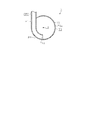
- the refrigerant pipe CP2 is attached along the tangential direction of the cylindrical portion 73a (see FIG. 4B).
- the second forming member 72 includes a cylindrical portion 72a that opens in the right direction and a bottom portion 72b that covers the left direction of the cylindrical portion 72a.
- the cylindrical portion 72 a is joined to the reduced diameter portion 74.
- a shunt pipe mounting hole 72c is provided in the bottom 72b.
- the branch pipe mounting holes 72c are provided at equal pitches in the circumferential direction around the central axis J2 of the cylindrical portion 72a (see FIG. 4C).
- a swirl flow forming chamber 70B and a speed increasing chamber 70C are formed as spaces constituting a part of the flow dividing chamber 70A.
- the swirl flow forming chamber 70B is partitioned and formed as a space surrounded by the cylindrical portion 73a and the bottom portion 73b of the pipe connecting portion 73.
- the speed increasing chamber 70 ⁇ / b> C is defined as a space in the reduced diameter portion 74. Further, the swirl flow forming chamber 70 ⁇ / b> B and the speed increasing chamber 70 ⁇ / b> C are partitioned at a connection portion between the cylindrical portion 73 a and the reduced diameter portion 74.
- a spray chamber 70D is formed as a space constituting a part of the flow dividing chamber 70A.
- the spray chamber 70D is partitioned and formed as a space excluding the speed increasing chamber 70C formed in the second forming member 72 from the space surrounded by the cylindrical portion 72a and the bottom portion 72b.
- an opening surface formed as a plane perpendicular to the central axis J2 at the right end of the reduced diameter portion 74 is defined as an inlet 70C1 of the speed increasing chamber 70C.
- an opening surface formed as a plane perpendicular to the central axis J2 at the right end of the reduced diameter portion 74 is defined as an outlet 70C2 of the speed increasing chamber 70C.
- the inlet 70C1 serves as a connection port connected to the swirl flow forming chamber 70B
- the outlet 70C2 serves as a connection port connected to the spray chamber 70D.
- the area of the inlet 70C1 is the largest of the cross-sectional areas obtained by cutting the speed increasing chamber 70C along a plane perpendicular to the central axis J2, and the area of the outlet 70C2 is the smallest of the cross-sectional areas.
- the cross-sectional area of the spray chamber 70D is formed to be larger than the area of the outlet 70C2 of the speed increasing chamber 70C.
- the cross-sectional area defined by the inner diameter R3 of the cylindrical portion 72a in the spray chamber 70D is larger than the area defined by the inner diameter R4 of the right end of the reduced diameter portion 74 constituting the outlet 70C2. It is formed as follows. Thus, when the refrigerant flows from the speed increasing chamber 70C to the spraying chamber 70D, the refrigerant flow path is enlarged.
- the refrigerant flowing from the refrigerant pipe CP2 into the flow dividing chamber 70A flows to the respective flow dividing pipes CP3 through the swirl flow forming chamber 70B, the speed increasing chamber 70C, and the spraying chamber 70D in this order.
- coolant is demonstrated with reference to FIG.
- the refrigerant jetted from the refrigerant pipe CP2 to the swirl flow forming chamber 70B flows along the inner peripheral surface of the cylindrical portion 73a.
- the inner peripheral surface of the cylindrical portion 73a that is, the phase portion, imparts a swirling component to the refrigerant flowing from the medium pipe CP2.
- a swirl component is imparted to the refrigerant.
- the refrigerant forms a swirling flow around the central axis J2.
- the turning center of the refrigerant does not completely coincide with the central axis J2. Then, as shown in FIG.
- the refrigerant in the swirl flow forming chamber 70B flows to the speed increasing chamber 70C while swirling. Since the refrigerant flowing into the speed increasing chamber 70C flows along the inner peripheral surface of the reduced diameter portion 74, the turning diameter of the refrigerant becomes smaller toward the left. As a result, the speed of the refrigerant increases toward the left in the speed increasing chamber 70C. In addition, the swirl diameter of the refrigerant is reduced and the speed increasing action stabilizes the swirl flow in the speed increasing chamber 70C, particularly when a two-phase refrigerant composed of gas and liquid flows into the expansion valve 6. Even if an intermittent two-phase flow that flows in from the pipe mounting hole 71a, the discontinuity of the density distribution is eliminated.
- the center of the swirling flow of the refrigerant can be brought closer to the central axis J2 by reducing the swirling diameter of the refrigerant as the speed increasing chamber 70C moves to the left.
- the refrigerant density in the circular cross section that is, the cross section obtained by cutting the first forming member 71 along a plane perpendicular to the central axis J2 in the speed increasing chamber 70C is the central axis. It is distributed in a circular contour line having the same center as J2.
- the spray chamber 70D has a refrigerant flow path larger than the outlet 70C2 of the speed increasing chamber 70C, so that a two-phase flow refrigerant composed of gas and liquid having a smooth density distribution increases while having a swirling component. It is diffused in the form of a mist in the spray chamber 70D while being pushed out from the fast chamber 70C. As a result, the gas-liquid ratio of the refrigerant can be made uniform.
- the refrigerant in the spray chamber 70D has a swirling component, it flows along the inner peripheral surface of the cylindrical portion 72a. That is, a swirling flow of the refrigerant is also formed in the spray chamber 70D. As a result, the refrigerant in the spray chamber 70D is evenly divided into the respective branch pipes CP3.
- the two-phase flow refrigerant composed of the gas and the liquid which is a mist jet and has a high flow velocity, is supplied to the flow divider 7 from the throttle portion 60C (see FIG. 3C) of the expansion valve 6, and the flow dividing chamber 7
- the refrigerant circulating in 70A forms a swirling flow.
- circulates the inside of the branch chamber 70A can exclude the influence of gravity.
- the flow divider 7 and the expansion valve 6 of the present embodiment allow the high-pressure liquid refrigerant to flow from the respective flow dividing pipes CP3 to the flow dividing chamber 70A during the cooling operation.
- the refrigerant flows in the order of the spray chamber 70D, the speed increasing chamber 70C, and the swirl flow forming chamber 70B.
- the high-pressure liquid refrigerant in the diversion chamber 70A flows to the throttle portion 60C via the refrigerant pipe CP1.
- the throttle portion 60C is formed to perform a throttle action for the purpose of controlling the degree of supercooling of the high-pressure liquid refrigerant.
- the high-pressure liquid refrigerant passing through the throttle unit 60C becomes a two-phase flow composed of gas and liquid atomized by the throttle action. And this refrigerant
- the flow dividing chamber 70A formed in the flow distributor main body 70 includes the swirl flow forming chamber 70B, the speed increasing chamber 70C, and the spraying chamber 70D.
- the swirling flow of the refrigerant becomes stable.
- the distribution of the refrigerant density in the circular cross section in the acceleration chamber 70C is stabilized.
- the refrigerant flows into the spray chamber 70D, the refrigerant is diffused in the form of a mist having a swirling component, so that the gas and the liquid become uniform.
- the flow divider 7 of the present embodiment it is possible to achieve both the stabilization of the swirling flow of the refrigerant and the uniformization of the gas and the liquid.
- the refrigerant flowing in the spray chamber 70D has a swirling component, the refrigerant flows along the inner peripheral surface of the cylindrical portion 73a. Therefore, it becomes possible to make the flow rate of the refrigerant flowing through the respective branch pipes CP3 arranged at equal pitches in the circumferential direction uniform.
- the speed increasing chamber 70C is defined by the space inside the reduced diameter portion 74 having a substantially conical shape. According to this configuration, an increase in the speed at which the refrigerant turns can be realized only by a part of the shape of the flow divider main body 70. Therefore, a dedicated instrument for increasing the speed at which the refrigerant turns can be omitted, so that the configuration of the flow divider 7 can be simplified. As a result, the cost of the shunt 7 can be reduced.
- the cross-sectional area of the spray chamber 70D is formed to be larger than the area of the outlet 70C2 of the speed increasing chamber 70C.
- a two-phase refrigerant composed of a gas and a liquid having a swirl component is diffused in the spray chamber 70D only by a partial shape relationship of the flow distributor body 70. Therefore, the configuration for stirring the refrigerant in the flow divider 7 can be simplified.
- a nozzle that diffuses into a uniform mist can be formed only by the relationship of the shape of a part of the flow distributor main body 70.
- the refrigerant pipe CP2 is connected along the tangential direction of the cylindrical portion 73a of the flow distributor main body 70.
- the refrigerant flowing from the refrigerant pipe CP2 to the swirl flow forming chamber 70B flows along the inner peripheral surface of the cylindrical portion 73a, so that a swirl component is imparted to the refrigerant. Therefore, since the refrigerant has a swirling component in advance, when the refrigerant flows from the swirl flow forming chamber 70B to the speed increasing chamber 70C, the refrigerant easily swirls in the speed increasing chamber 70C.
- the throttle portion 60C of the expansion valve 6 is configured to be throttled to have a variable opening corresponding to the refrigeration load. According to this configuration, unlike the throttle part with a constant opening degree that is attached to a conventional shunt, the throttle part changes to an appropriate throttle degree depending on the operating conditions such as the flow rate and the dryness. Can be improved.
- the two-phase flow refrigerant composed of the gas and liquid as the mist jet flow from the expansion valve 6 forms a swirl flow in the diversion chamber 70A, and therefore the refrigerant flowing through the diversion chamber 70A. Will greatly reduce the effect of gravity. Therefore, since it is avoided that arrangement
- the expansion valve 6 and the flow divider 7 are arranged close to each other. According to this configuration, even when a two-phase flow refrigerant composed of gas and liquid flows into the expansion valve 6, the rectifying action due to the swirling flow in the diversion chamber 70A mitigates intermittent fluctuations in the jet flow, so that intermittent refrigerant noise is generated. Can be reduced.
- FIG. 6 a second embodiment in which the shunt of the present invention is embodied as a shunt connected to an expansion valve mounted on a heat pump type refrigeration apparatus will be described.
- the flow divider 7 of the present embodiment is different from the flow divider 7 of the first embodiment in the shape of the pipe connection portion 73 of the flow divider main body 70.
- the description will focus on the differences from the first embodiment.
- the solid line arrow in the flow splitter main-body part 70 has shown the flow of the refrigerant
- the pipe connection portion 73 includes a diameter-enlarged portion 73 c that opens in the left direction and expands in diameter toward the left direction, and a bottom portion 73 d that covers an end portion in the right direction of the diameter-enlarged portion 73 c.
- the enlarged diameter portion 73c is provided with a pipe attachment hole 71a. Further, the left end of the enlarged diameter portion 73c and the right end of the reduced diameter portion 74 are connected to each other. In other words, the area of the opening formed at the end of the enlarged diameter portion 73c is the same as the area of the inlet 70C1 of the reduced diameter portion 74 (speed increasing chamber 70C).
- the swirl flow forming chamber 70B is partitioned and formed by a space surrounded by the enlarged diameter portion 73c and the bottom portion 73d. Moreover, the refrigerant
- the refrigerant flowing from the refrigerant pipe CP2 to the swirl flow forming chamber 70B is given a flow component toward the speed increasing chamber 70C in addition to being given a swirl component by the enlarged diameter portion 73c. become.
- the enlarged diameter part 73c has played the role of the guide part which guides a refrigerant
- the refrigerant flows from the swirl flow forming chamber 70B to the speed increasing chamber 70C.
- the refrigerant flow in the acceleration chamber 70C and the spray chamber 70D is the same as that in the first embodiment.
- the refrigerant flowing from the refrigerant pipe CP2 to the swirl flow forming chamber 70B is given a swirl component and a flow component toward the speed increasing chamber 70C by the enlarged diameter portion 73c. For this reason, the flow rate of the refrigerant toward the bottom portion 73d of the pipe connection portion 73 is suppressed. Therefore, the refrigerant in the swirl flow forming chamber 70B efficiently flows to the speed increasing chamber 70C.
- FIG. 7 a third embodiment in which the flow divider of the present invention is embodied as a flow divider connected to an expansion valve mounted in a heat pump type refrigeration apparatus will be described.
- the flow divider 7 of the present embodiment is different from the flow divider 7 of the first embodiment in the shape of the pipe connection portion 73 of the flow divider main body 70.
- the description will focus on the differences from the first embodiment.
- the solid line arrow in the flow splitter main-body part 70 has shown the flow of the refrigerant
- the pipe connection portion 73 includes a substantially cylindrical cylindrical portion 73e that is open in the left direction and is inclined downward in the left direction, and a bottom portion that covers an end portion in the right direction of the cylindrical portion 73e. 73f.
- the cylindrical portion 73e is provided with a pipe mounting hole 71a.
- the left end portion of the cylindrical portion 73e and the right end portion of the reduced diameter portion 74 are connected to each other. That is, the area of the opening formed at the end of the cylindrical portion 73e is the same as the area of the inlet 70C1 of the reduced diameter portion 74 (speed increasing chamber 70C).
- the swirl flow forming chamber 70B is partitioned and formed by a space surrounded by the cylindrical portion 73e and the bottom portion 73f.
- the refrigerant pipe CP2 is attached along the tangential direction of the enlarged diameter portion 73c.
- the refrigerant flowing from the refrigerant pipe CP2 to the swirling flow forming chamber 70B is given a flow component toward the speed increasing chamber 70C in addition to being given a swirling component by the cylindrical portion 73e.
- the cylindrical part 73e plays the role of the guide part which guides a refrigerant
- the refrigerant flows from the swirl flow forming chamber 70B to the speed increasing chamber 70C.
- the refrigerant flow in the acceleration chamber 70C and the spray chamber 70D is the same as that in the first embodiment.
- FIG. 8 a fourth embodiment in which the flow divider of the present invention is embodied as a flow divider connected to an expansion valve mounted in a heat pump type refrigeration apparatus will be described.
- the flow divider 7 of the present embodiment is different in the dimensional relationship between the pipe connection portion 73 and the reduced diameter portion 74 of the flow divider main body 70.
- the description will focus on the differences from the first embodiment.
- the inner diameter R5 of the cylindrical portion 73a of the pipe connecting portion 73 is formed to be larger than the inner diameter R6 of the end portion in the right direction of the reduced diameter portion 74. That is, the inner diameter of the swirl flow forming chamber 70B is formed to be larger than the inner diameter of the inlet 70C1 of the speed increasing chamber 70C.
- a substantially circular connecting portion 75 is provided at the left end of the cylindrical portion 73a.
- the swirl flow forming chamber 70 ⁇ / b> B is partitioned and formed by a space surrounded by the cylindrical portion 73 a, the bottom portion 73 b, and the connecting portion 75.
- coolant piping CP2 is attached along the tangent direction of the cylindrical part 73a similarly to 1st Embodiment.
- the refrigerant flowing from the refrigerant pipe CP2 to the swirl flow forming chamber 70B is given a swirl component by the cylindrical portion 73a. Then, the refrigerant in the swirl flow forming chamber 70B is temporarily retained by the connecting portion 75 before flowing into the speed increasing chamber 70C, so that the swirl component of the refrigerant increases. Specifically, the flow component from the swirl flow forming chamber 70B to the speed increasing chamber 70C is restricted by the connecting portion 75, so that the frequency of the refrigerant swirling in the swirl flow forming chamber 70B increases. In this state of the refrigerant, the refrigerant flows into the acceleration chamber 70C. The refrigerant flow in the acceleration chamber 70C and the spray chamber 70D is the same as that in the first embodiment.
- the refrigerant in the swirl flow forming chamber 70B is temporarily retained by the connecting portion 75 before flowing into the speed increasing chamber 70C. According to this configuration, the swirl component of the refrigerant applied in the swirl flow forming chamber 70B can be increased. As a result, the swirling flow of the refrigerant flowing into the acceleration chamber 70C can be stabilized.
- the flow divider of the present invention is embodied as a flow divider connected to an expansion valve mounted on a heat pump type refrigeration apparatus.
- the flow divider 7 of the present embodiment is provided with an enlarged space 70E between the swirl flow forming chamber 70B and the speed increasing chamber 70C of the flow divider main body 70. It is different in point.
- the description will focus on the differences from the first embodiment.
- the connecting portion 76 is formed in a shape that is recessed outward with respect to the central axis J2.
- an enlarged space 70 ⁇ / b> E is formed by a space surrounded by the connecting portion 76, the right end of the reduced diameter portion 74 and the left end of the pipe connecting portion 73.
- the inner diameter R7 by the inner peripheral surface of the connecting portion 76 is formed so as to be larger than both the inner diameter R5 of the cylindrical portion 73a and the inner diameter R6 of the right end portion of the reduced diameter portion 74. That is, the inner diameter of the expansion space 70E is formed to be larger than the inner diameter of the swirl flow forming chamber 70B and the inner diameter of the inlet 70C1 of the speed increasing chamber 70C.
- the inner diameter R5 of the cylindrical portion 73a and the inner diameter R6 of the reduced diameter portion 74 are formed to be equal to each other. That is, the inner diameter of the swirl flow forming chamber 70B and the inner diameter of the inlet 70C1 of the speed increasing chamber 70C are formed to be equal to each other.
- the refrigerant flowing from the refrigerant pipe CP2 to the swirl flow forming chamber 70B is given a swirl component by the cylindrical portion 73a.
- the refrigerant in the swirl flow forming chamber 70B once stays in the enlarged space 70E and flows into the speed increasing chamber 70C. Thereby, the refrigerant whose swirl component is increased by the enlarged space 70E flows into the acceleration chamber 70C.
- the refrigerant flow in the acceleration chamber 70C and the spray chamber 70D is the same as that in the first embodiment.
- an effect according to the effect (9) of the fourth embodiment can be achieved. .
- FIG. 10 a sixth embodiment in which the flow divider of the present invention is embodied as a flow divider connected to an expansion valve mounted on a heat pump type refrigeration apparatus will be described.
- the flow divider 7 of the present embodiment is provided with a connection space 70F between the speed increasing chamber 70C and the spraying chamber 70D of the flow divider body 70, The difference is that a connecting portion 75 a is provided between the enlarged diameter portion 73 c and the reduced diameter portion 74.
- the difference between the second embodiment will be mainly described.
- the current divider main body 70 is configured as a single member.
- a substantially annular connection that connects them to each other.
- a portion 75a is provided.
- a cylindrical connecting passage portion 78 is provided between the left end portion of the reduced diameter portion 74 and the right end portion of the flow dividing pipe connecting portion 77 corresponding to the second forming member 72 of the second embodiment. Is provided.
- the inner diameter R8 (maximum diameter) at the left end of the enlarged diameter portion 73c is formed to be larger than the inner diameter R6 (maximum diameter) at the right end of the reduced diameter portion 74. That is, the inner diameter of the swirl flow forming chamber 70B is formed to be larger than the inner diameter of the inlet 70C1 of the speed increasing chamber 70C.
- the inner diameter R9 of the inner peripheral surface of the connection passage portion 78 is formed to be the same as the inner diameter R10 (minimum diameter) of the left end portion of the reduced diameter portion 74. That is, the inner diameter of the connection space 70F and the inner diameter of the outlet 70C2 of the speed increasing chamber 70C are formed to be the same.
- the inner diameter R9 is formed so as to be constant over the entire connection passage portion 78.
- the swirl flow forming chamber 70B is formed by a space surrounded by the enlarged diameter portion 73c, the bottom portion 73d, and the connecting portion 75a.
- the connection space 70 ⁇ / b> F is formed by a space formed inside the connection passage portion 78.
- the connection space 70F communicates the speed increasing chamber 70C and the spraying chamber 70D with each other.
- the refrigerant flowing from the refrigerant pipe CP2 to the swirl flow forming chamber 70B is given a swirl component and a flow direction component toward the speed increasing chamber 70C by the enlarged diameter portion 73c. Then, the refrigerant in the swirl flow forming chamber 70B temporarily stays before flowing into the acceleration chamber 70C by the connecting portion 75a. Thereby, the swirl component of the refrigerant can be increased. And the speed in which the refrigerant
- the refrigerant flowing from the speed increasing chamber 70C to the connection space 70F is a cylindrical space having a constant inner diameter, so that the turning speed of the refrigerant becomes stable.
- the refrigerant flowing from the connection space 70F to the spraying chamber 70D has a refrigerant flow path larger than the outlet 70C2 of the speed increasing chamber 70C, so that the jet energy of the refrigerant is diffused in the spraying chamber 70D.
- the outlet 70C2 of the speed increasing chamber 70C functions as a nozzle for ejecting uniform refrigerant.
- coolant in spraying chamber 70D has a turning component, it flows along the internal peripheral surface of the cylindrical part 73a. As a result, the refrigerant in the spray chamber 70D is evenly divided into the respective branch pipes CP3.
- the diverter body 70 is provided with the enlarged diameter portion 73c and the connecting portion 75a.
- the refrigerant flowing from the refrigerant pipe CP2 to the swirl flow forming chamber 70B is given a swirl component and a flow direction component toward the speed increasing chamber 70C by the diameter-expanding portion 73c, and the connecting portion 75a
- the swirl component increases.
- the refrigerant in the swirl flow forming chamber 70B can be efficiently circulated into the speed increasing chamber 70C and the swirl flow of the refrigerant can be stabilized.
- connection space 70F is provided between the acceleration chamber 70C and the spray chamber 70D.
- the spraying chamber 70D moves away from the pipe mounting hole 71a, and the fluctuation of the refrigerant in the pipe mounting hole 71a in the connection space 70F occurs.
- the influence can be mitigated and the swirling flow of the refrigerant can be stabilized.
- the swirling flow of the refrigerant in the spray chamber 70D can be stabilized, so that the refrigerant flow rate can be evenly distributed to each branch pipe CP3. become able to.
- FIG. 11 a seventh embodiment in which the flow divider of the present invention is embodied as a flow divider connected to an expansion valve mounted on a heat pump type refrigeration apparatus will be described.
- the shunt 7 of this embodiment differs from the shunt 7 of the sixth embodiment in the configuration of the connection space 70F.
- the difference from the sixth embodiment will be mainly described.
- connection passage portion 78 is connected to a cylindrical portion 78a formed in a cylindrical shape having a constant inner diameter, and a left end portion of the cylindrical portion 78a and expands toward the left direction. And an enlarged diameter portion 78b.
- the enlarged diameter portion 78b is formed in a tapered shape.
- the connection space 70F is defined by a space surrounded by the cylindrical portion 78a and the enlarged diameter portion 78b.
- the connection space 70F includes a constant-diameter chamber 70F1 defined by the internal space of the cylindrical portion 78a and an enlarged-diameter chamber 70F2 defined by the internal space of the enlarged-diameter portion 78b.
- the inner diameter R11 of the left end of the enlarged diameter portion 78b is formed to be equal to the inner diameter R12 of the branch pipe connecting portion 77. That is, the area of the connection port of the connection space 70F with the spray chamber 70D is formed to be equal to the cross-sectional area of the spray chamber 70D.
- the refrigerant flowing from the speed increasing chamber 70C to the connection space 70F stabilizes the swirling flow in the constant diameter chamber 70F1.
- the refrigerant flowing from the constant-diameter chamber 70F1 to the enlarged-diameter chamber 70F2 stabilizes the inflow into the spray chamber 70D by gradually increasing the swirl diameter of the refrigerant in the enlarged-diameter chamber 70F2.
- the flow of the refrigerant in the swirl flow forming chamber 70B, the speed increasing chamber 70C, and the spraying chamber 70D is the same as that in the sixth embodiment.
- the constant diameter chamber 70F1 and the enlarged diameter chamber 70F2 are provided in the connection passage portion 78. According to this configuration, the swirling flow of the refrigerant is stabilized by the constant diameter chamber 70F1, and the refrigerant can be smoothly circulated to the spraying chamber 70D by the expansion chamber 70F2.
- FIG. 12 an eighth embodiment in which the flow divider of the present invention is embodied as a flow divider connected to an expansion valve mounted on a heat pump type refrigeration apparatus will be described.
- the flow divider 7 of the present embodiment is different from the flow divider 7 of the sixth embodiment in that the dimensional relationship between the spray chamber 70D and the speed increasing chamber 70C is different and the connection space 70F is omitted.
- the difference from the sixth embodiment will be mainly described.
- the speed increasing chamber 70C and the spraying chamber 70D are in direct communication with each other. Further, the inner peripheral surface 77b of the cylindrical portion 77a constituting the flow dividing pipe connecting portion 77 is reduced in diameter toward the left direction, that is, toward the flow dividing pipe CP3. The inner peripheral surface 77b is smoothly connected to the inner peripheral surface of each branch pipe CP3.
- the inner diameter R13 of the virtual circle C1 formed by connecting the inner edges of the respective branch pipes CP3 is larger than the inner diameter R10 (minimum diameter) of the outlet 70C2 of the speed increasing chamber 70C. Is formed. That is, each branch pipe CP3 is arranged to be outside the inner diameter R10 of the outlet 70C2.
- the refrigerant flowing from the speed increasing chamber 70C to the spraying chamber 70D is prevented from directly colliding with the flow dividing pipe CP3. That is, the refrigerant flowing from the outlet 70C2 of the speed increasing chamber 70C to the spraying chamber 70D collides with the bottom 72b.
- the virtual circle C1 is formed so as to be larger than the inner diameter R10 of the speed increasing chamber 70C, so that the refrigerant flowing from the speed increasing chamber 70C to the spray chamber 70D collides with the bottom 73d. . Accordingly, the refrigerant is easily diffused in the spray chamber 70D together with the swirl component, and the instability of the transient state can be reduced. As a result, the refrigerant is agitated in the spray chamber 70D and then circulates in each branch pipe CP3. The refrigerant flow in the swirl flow forming chamber 70B and the speed increasing chamber 70C is the same as that in the sixth embodiment.
- the virtual circle C1 of each branch pipe CP3 is formed to be larger than the inner diameter R10 (minimum diameter) of the outlet 70C2 of the speed increasing chamber 70C. According to this configuration, the refrigerant flowing from the speed increasing chamber 70C to the spraying chamber 70D can be prevented from flowing directly to each branch pipe CP3. As a result, the swirling flow of the refrigerant in the speed increasing chamber 70C becomes unstable, so that even when the refrigerant gas and liquid are not sufficiently stirred, the spray chamber 70D before the refrigerant flows into the branch pipe CP3. The refrigerant can be stirred in
- the diameter of the inner peripheral surface 77b of the cylindrical portion 77a of the flow dividing pipe connecting portion 77 decreases toward the flow dividing pipe CP3, and is smoothly connected to the inner peripheral surface of each flow dividing pipe CP3. It is a configuration. According to this configuration, the refrigerant swirled in the spray chamber 70D smoothly flows to each branch pipe CP3.
- FIG. 13 a ninth embodiment in which the flow divider of the present invention is embodied as a flow divider connected to an expansion valve mounted on a heat pump type refrigeration apparatus will be described.
- the flow divider 7 of the present embodiment is different from the flow divider 7 of the sixth embodiment in that the shape of the spray chamber 70D is different and the connection space 70F is omitted.
- the difference from the sixth embodiment will be mainly described.
- the speed increasing chamber 70C and the spraying chamber 70D are in direct communication with each other.
- the inner diameter R14 of each branch pipe CP3 is formed to be larger than the inner diameter R15 of each branch pipe CP3 of the sixth embodiment.
- the inner diameter of the branch pipe mounting hole 72c is formed so as to be larger than the inner diameter of the branch pipe mounting hole 72c of the sixth embodiment.
- the speed of the refrigerant flowing from the spray chamber 70D to each branch pipe CP3 is reduced.
- the shunt characteristics tend to improve without depending on the shunt performance of the shunt.
- the gas-rich refrigerant starts to flow through one of the plurality of shunts when the refrigerant is in a completely sprayed state. Then, since the flow velocity is increased, the gas-rich refrigerant having a low density is further intensively circulated through the branch pipes due to the jet action, and there is a problem that it is difficult to distribute the refrigerant to each of the branch pipes at an equal flow rate.
- the refrigerant since the refrigerant swirls in the spray chamber 70D, the refrigerant can be distributed to each of the diversion pipes at a uniform flow rate almost without depending on the inner diameter of the diversion pipe. Therefore, even if the inner diameter R14 of the branch pipe CP3 is increased to reduce the flow rate of the refrigerant, it can be distributed to each of the branch pipes at a uniform flow rate.
- the inner diameter R14 of each branch pipe CP3 is formed to be larger than the inner diameter R15 of each branch pipe CP3 of the sixth embodiment. According to this configuration, since the speed of the refrigerant flowing from the spray chamber 70D to each branch pipe CP3 is reduced and the refrigerant swirls in the spray chamber 70D, the distribution characteristics are temporarily unbalanced in a transient state or the like. However, the unbalance can be eliminated by the refrigerant crossing each branch pipe mounting hole 72c by the swirl component.
- the flow divider 7 of the present embodiment differs from the flow divider 7 of the first embodiment in the connection mode between the refrigerant pipe CP2 and the pipe connection portion 73. Further, the refrigerant pipe CP2 and the flow divider main body 70 are different in that they are formed as a seamless integrated structure. Hereinafter, the description will focus on the differences from the first embodiment.
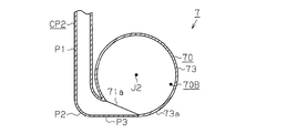
- the refrigerant pipe CP ⁇ b> 2 is disposed outside the cylindrical part 73 a of the pipe connection part 73. Specifically, the amount of eccentricity H1 from the central axis J2 of the refrigerant pipe CP2 is larger than the amount of eccentricity H2 from the central axis J2 of the refrigerant pipe CP2 of the first embodiment (see FIG. 4B). Is formed.
- the eccentric amount H1 from the central axis J2 of the refrigerant pipe CP2 is larger than the eccentric amount H2 from the central axis J2 of the refrigerant pipe CP2 of the first embodiment (see FIG. 4B). This means the following:
- r>H1> H2 and H1a> r are satisfied.
- the distance between the inner wall surface of the wall and the central axis J2 H2 the amount of eccentricity in the first embodiment, that is, from the central axis J2 of the refrigerant pipe CP2 when the refrigerant pipe is installed so that H1a is equal to r
- connection part 73g which connects the refrigerant
- the connecting portion 73g plays a role of guiding the refrigerant in the refrigerant pipe CP2 along the tangential direction with respect to the inner peripheral surface of the cylindrical portion 73a.
- the connecting portion 73g is preferably connected along the tangential direction to the inner peripheral surface of the cylindrical portion 73a. However, in FIG. And is slightly facing the central axis J2.
- the refrigerant flowing from the refrigerant pipe CP2 to the swirl flow forming chamber 70B flows along the connecting portion 73g from the refrigerant pipe CP2.
- coolant of the flow along the connection part 73g flows toward the cylindrical part 73a.
- the flow of the refrigerant in the acceleration chamber 70C and the spray chamber 70D is the same as that in the first embodiment.
- the refrigerant pipe CP2 is disposed outside the cylindrical portion 73a, and the connecting portion 73g is provided between the refrigerant pipe CP2 and the cylindrical portion 73a.
- the flow rate of the refrigerant flowing in from the refrigerant pipe CP2 is too high, a local vortex is generated around the pipe attachment hole 71a, and the turning center is easily displaced from the central axis J2. In that case, the flow velocity of the refrigerant flowing into the refrigerant pipe CP2 can be reduced by increasing the inner diameter of the refrigerant pipe CP2.
- increasing the inner diameter reduces the amount of eccentricity between the refrigerant pipe CP2 and the central axis J2.
- Increasing the inner diameter of the swirl flow forming chamber 70B can increase the amount of eccentricity between the refrigerant pipe CP2 and the central axis J2, but increasing the inner diameter of the swirl flow forming chamber 70B increases the size of the flow divider 7. End up.
- the flow rate of the refrigerant flowing into the diverting chamber 70A can be reduced without increasing the diameter of the swirling flow forming chamber 70B and securing the eccentric amount. Therefore, a swirling flow of the refrigerant having a center close to the central axis J2 of the flow dividing chamber 70A is easily formed in the swirling flow forming chamber 70B.
- the flow divider 7 of the present embodiment differs from the flow divider 7 of the first embodiment in the connection mode between the refrigerant pipe CP2 and the pipe connection portion 73. Further, the refrigerant pipe CP2 and the flow divider main body 70 are different in that they are formed as a seamless integrated structure. Hereinafter, the description will focus on the differences from the first embodiment.
- the refrigerant pipe CP ⁇ b> 2 is disposed outside the cylindrical part 73 a of the pipe connection part 73.
- the refrigerant pipe CP2 includes a cylindrical pipe part P1 disposed outward from the cylindrical part 73a, a curved pipe part P2 that curves from the cylindrical pipe part P1 toward the cylindrical part 73a, and the curved pipe part P2 and the cylindrical part. And a connecting pipe part P3 that connects the two parts 73a to each other.
- the connection pipe portion P3 is formed as a planar wall extending along the tangential direction of the cylindrical portion 73a at the connection position with the cylindrical portion 73a.
- the liquid-rich refrigerant flows outside the curved pipe portion P2, and the gas-rich refrigerant flows inside the curved pipe portion P2, so that the density distribution of the refrigerant flowing into the swirl flow forming chamber 70B is stable. Will come to be.
- the curved pipe portion P2 is provided in the refrigerant pipe CP2. According to this configuration, it is possible to reduce the instability of the refrigerant flowing into the swirl flow forming chamber 70B by the curved pipe portion P2. Accordingly, the swirl flow formed by the refrigerant in the swirl flow forming chamber 70B is stabilized.
- FIG. 16 a twelfth embodiment in which the flow divider of the present invention is embodied as a flow divider connected to an expansion valve mounted on a heat pump type refrigeration apparatus will be described.
- the flow divider 7 of the present embodiment differs from the flow divider 7 of the first embodiment in the connection mode between the refrigerant pipe CP2 and the pipe connection portion 73.
- the description will focus on the differences from the first embodiment.
- the refrigerant pipe CP ⁇ b> 2 is disposed outside the cylindrical part 73 a of the pipe connection part 73.
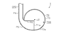
- the refrigerant pipe CP2 includes a cylindrical pipe part P4 disposed outside the cylindrical part 73a, a curved pipe part P5 that curves from the cylindrical pipe part P4 toward the cylindrical part 73a, and a cylindrical part from the curved pipe part P5. And an inner piping part P6 extending inward from 73a.
- the inner piping part P6 is provided so as to be positioned near the central axis J2 of the flow divider 7 (pipe connecting part 73).
- the refrigerant pipe CP2 is provided with the curved pipe part P5 and the inner pipe part P6, and the inner pipe part P6 is located near the central axis J2 that is the center of the cylindrical part 73a. It is provided as follows. According to this configuration, since the gas-rich refrigerant easily flows into the central axis J2, the refrigerant can easily form a swirling flow around the central axis J2. Therefore, the swirling flow of the refrigerant in the swirling flow forming chamber 70B can be stabilized.
- FIG. 17 a thirteenth embodiment in which the flow divider of the present invention is embodied as a flow divider connected to an expansion valve mounted on a heat pump type refrigeration apparatus will be described.
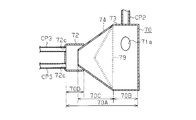
- the flow divider 7 of this embodiment is different from the flow divider 7 of the first embodiment in that a porous permeable material 79 is provided.
- a porous permeable material 79 is provided.
- a porous permeable material 79 is provided inside the reduced diameter portion 74.
- the porous permeable material 79 is connected to the right end of the reduced diameter portion 74 over the entire circumference and is formed in a shape that is recessed in a conical shape toward the left.
- foamed metal, ceramic, foamable resin, mesh-like material, perforated plate, or the like is used as the material of the porous permeable material 79.
- the refrigerant flowing from the swirl flow forming chamber 70B to the speed increasing chamber 70C is captured by the porous permeation material 79 of dust contained in the refrigerant.
- the flow of the refrigerant in the swirl flow forming chamber 70B, the speed increasing chamber 70C, and the spraying chamber 70D is the same as that in the first embodiment.
- the current divider 7 of the present embodiment in addition to the effects (1) to (7) of the first embodiment, the following effects can be obtained.
- a filter porous permeation material that supplements contamination and the like is provided near the throttle portion of the expansion valve.
- providing a filter in the vicinity of the throttle portion requires a space for installing the filter, and there is a problem that the expansion valve becomes large.
- the porous permeable material 79 is provided in the flow divider 7, the porous permeable material is compared with the configuration in which the porous permeable material 79 is provided in the expansion valve 6.
- the space for providing can be omitted. Therefore, the expansion of the expansion valve 6 can be suppressed.
- FIG. 18 a fourteenth embodiment in which the flow divider of the present invention is embodied as a flow divider connected to an expansion valve mounted on a heat pump type refrigeration apparatus will be described.
- the flow divider 7 of this embodiment differs in the connection structure with respect to the expansion valve 6 compared with the flow divider 7 of 1st Embodiment.
- the description will focus on the differences from the first embodiment.
- the flow divider 7 is connected to the refrigerant pipe CP1. That is, the expansion valve 6 and the flow divider 7 are connected to each other by the refrigerant pipe CP1. And the expansion valve 6 and the indoor side expansion valve 4 (refer FIG. 1) are mutually connected by refrigerant
- the high-pressure refrigerant passes through the refrigerant pipe CP2 as a single-phase or two-phase refrigerant composed of gas and liquid, and is reduced in pressure by the throttle portion 60C of the expansion valve 6 to become a two-phase flow composed of gas and liquid.
- the refrigerant pipe CP1 is circulated.
- the refrigerant flows from the refrigerant pipe CP1 to the flow dividing chamber 70A of the flow divider 7.
- the flow of the refrigerant in the branch chamber 70A is the same as that in the first embodiment.
- the current divider 7 of the present embodiment it is possible to achieve the effects according to the effects (1) to (7) of the first embodiment.
- the shunt of the present invention is not limited to the above embodiments, and each of the above embodiments can also be applied to a case where different embodiments are combined with each other. Moreover, the shunt of this invention is not limited to said each embodiment, The following changes are also possible. The following modifications are not only applied to the above-described embodiments, but can also be applied when different modifications are performed in combination with each other.
- the reduced diameter portion 74 is provided in a substantially conical shape that decreases in diameter at a constant rate from the right to the left, but the shape of the reduced diameter portion 74 is limited to this. There is nothing.
- a first reduced diameter portion 74 a connected to the pipe connecting portion 73 and a second reduced diameter portion 74 b connected to the second forming member 72 can also consist of two reduced diameter parts.
- the first reduced diameter portion 74a and the second reduced diameter portion 74b are provided such that the ratio of diameter reduction, that is, the taper angle as the cross section of the reduced diameter portion 74 is different.
- the taper angle ⁇ 2 of the second reduced diameter portion 74b is formed to be larger than the taper angle ⁇ 1 of the first reduced diameter portion 74a.
- the taper angle ⁇ 1 of the first reduced diameter portion 74a can be formed to be larger than the taper angle ⁇ 2 of the second reduced diameter portion 74b.
- the length of the left-right direction of the 1st diameter reducing part 74a and the 2nd diameter reducing part 74b is not limited to the relationship shown to Fig.19 (a) and (b).
- the reduced diameter portion 74 can be formed so that its cross section is curved in the left-right direction.
- the pipe connecting portion 73 is provided with the enlarged diameter portion 73c, and the enlarged diameter portion 73c and the reduced diameter portion 74 are connected by the connecting portion 75a.
- the structure of and the connection structure of the pipe connection part 73 and the reduced diameter part 74 are not limited to this.
- the configuration of the pipe connection portion 73 and the connection structure of the pipe connection portion 73 and the reduced diameter portion 74 in the first embodiment can also be used.
- the effect according to the effect (10) of 6th Embodiment can be show
- the cylindrical portion 73 a of the pipe connection portion 73 having the configuration of FIG. 20 can be changed to the enlarged diameter portion 73 c in the second embodiment. Even in this configuration, it is possible to achieve an effect according to the effect (10) of the sixth embodiment.
- the pipe connecting portion 73 is provided with the enlarged diameter portion 73c, and the enlarged diameter portion 73c and the reduced diameter portion 74 are connected by the connecting portion 75a.
- the configuration of the pipe connection portion 73 and the connection structure between the pipe connection portion 73 and the reduced diameter portion 74 are not limited to this.
- the configuration of the pipe connection portion 73 and the connection structure of the pipe connection portion 73 and the reduced diameter portion 74 in the first embodiment can be used. According to this structure, the effect according to the effect (12) of 7th Embodiment can be show
- the cylindrical portion 73 a of the pipe connection portion 73 having the configuration of FIG. 20 can be changed to the enlarged diameter portion 73 c in the second embodiment. Even in this configuration, it is possible to achieve an effect according to the effect (12) of the seventh embodiment.
- the pipe connecting portion 73 is provided with the enlarged diameter portion 73c, and the enlarged diameter portion 73c and the reduced diameter portion 74 are connected by the connecting portion 75a.
- the configuration of the pipe connection portion 73 and the connection structure between the pipe connection portion 73 and the reduced diameter portion 74 are not limited to this.
- the configuration of the pipe connection portion 73 and the connection structure of the pipe connection portion 73 and the reduced diameter portion 74 in the first embodiment can be used. According to this structure, the effect according to the effect (13) of 8th Embodiment can be show
- the cylindrical portion 73 a of the pipe connection portion 73 having the configuration of FIG. 22 can be changed to the enlarged diameter portion 73 c in the second embodiment. Even in this configuration, the effect according to the effect (13) of the eighth embodiment can be obtained.
- the pipe connection portion 73 is provided with the enlarged diameter portion 73c, and the enlarged diameter portion 73c and the reduced diameter portion 74 are connected by the connecting portion 75a.
- the configuration of the pipe connection portion 73 and the connection structure between the pipe connection portion 73 and the reduced diameter portion 74 are not limited to this.
- the configuration of the pipe connection portion 73 and the connection structure of the pipe connection portion 73 and the reduced diameter portion 74 in the first embodiment can also be used. According to this structure, the effect according to the effect (15) of 9th Embodiment can be show
- the cylindrical portion 73a of the pipe connection portion 73 having the configuration of FIG. 23 can be changed to the enlarged diameter portion 73c in the second embodiment. Even in this configuration, an effect according to the effect (15) of the ninth embodiment can be obtained.
- the opening surface at the left end of the reduced diameter portion 74 is formed in a plane along the vertical direction, but the shape of the opening surface is not limited to this.
- the opening surface may be inclined with respect to the vertical direction. According to this configuration, the flow direction of the refrigerant flowing from the speed increasing chamber 70C toward the spray chamber 70D into the spray chamber 70D can be adjusted. Therefore, when the flow rate of the refrigerant in each branch pipe CP3 is adjusted to be different, the above structure is suitable.
- a cut-out portion 74c may be provided at the left end portion of the reduced diameter portion 74.
- the opening surface of the reduced diameter portion 74 can be formed by a plane along the vertical direction.
- three shunt pipes CP3 are provided at equal pitches in the circumferential direction, but the number and arrangement of the shunt pipes CP3 are not limited to this.
- one shunt pipe CP3 may be provided at the center.
- the connecting portion 76 is formed in a shape that is recessed outward, but the shape of the connecting portion 76 is not limited to this.
- the shape of a part of the connecting portion 76 in the right direction may be a tapered shape that increases in diameter toward the left. According to this configuration, the refrigerant in the swirl flow forming chamber 70B can be smoothly circulated into the enlarged space 70E.
- the shunt main body 70 is formed by joining the first forming member 71 and the second forming member 72 together, and in the sixth to ninth embodiments, although the shunt main body 70 is formed as a single member, the configuration of the shunt main body 70 is not limited to this.
- the shunt main body 70 of the first to fifth embodiments can be configured as a single member.
- the current divider main body 70 of the sixth to ninth embodiments can be constituted by two members, a first forming member 71 and a second forming member 72.
- there is no description of the configuration of the flow distributor main body 70 but it can be configured as a single member or can be configured from two members.
- segmentation structure of the shunt main body part 70 it is not limited to two members, the 1st formation member 71 and the 2nd formation member 72.
- the pipe connection part 73 and the reduced diameter part 74 can also be formed by different members.
- the throttle portion 60C is formed by the valve drive device as the expansion valve 6 so that the opening degree is variable, but the throttle portion 60C is not limited to this.
- the valve drive device, the valve rod 64, and the valve body 65 may be omitted, and only the valve hole 60B may be formed. Even in this configuration, effects other than the effect (5) of the first embodiment can be obtained.
- the expansion valve 6 and the flow divider 7 are connected to each other by the refrigerant pipe CP2 that is a connection pipe.
- the connection structure with 7 is not limited to this.
- the expansion valve 6 and the flow divider 7 can also be configured as an integral structure. Specifically, the second pipe mounting hole 62 of the expansion valve 6 and the pipe mounting hole 71a of the flow distributor main body 70 are directly connected. According to this configuration, since the refrigerant pipe CP2 can be omitted, it is possible to suppress an increase in size of the entire assembly of the expansion valve 6 and the flow divider 7. In addition, it is possible to reduce intermittent refrigerant noise that occurs when a two-phase refrigerant composed of gas and liquid flows into the expansion valve 6.
- the flow distributor main body 70 and the refrigerant pipe CP2 are configured as a seamless integrated structure, but the connection mode between the flow divider main body 70 and the refrigerant pipe CP2 Is not limited to this.
- the shunt main body 70 and the refrigerant pipe CP2 may be configured by separate members and then fixed to each other. .
- the expansion valve 6 is applied to the refrigeration apparatus 1, but the application example of the expansion valve 6 is not limited to this.
- the flow divider 7 is applied as a mode of connecting to the expansion valve 6, but the application example of the flow divider 7 is not limited to this.
- the flow divider 7 can be applied as long as it generates a two-phase flow composed of a gas and a liquid, such as an orifice, a nozzle, and an ejector.
Landscapes
- Engineering & Computer Science (AREA)
- Physics & Mathematics (AREA)
- Mechanical Engineering (AREA)
- Thermal Sciences (AREA)
- General Engineering & Computer Science (AREA)
- Geometry (AREA)
- Lift Valve (AREA)
Abstract
分流器(7)は、内部に冷媒が流通する分流室(70A)を有する分流器本体部(70)と、この分流器本体部(70)に設けられた第1配管取付孔71a、及びこの第1配管取付孔(71a)を介して分流室(70A)内に流入した冷媒を分流して流出するための分流管(CP3)が接続される第2配管取付孔(72c)とを備えている。分流室(70A)は、第1配管取付孔(71a)から流入される冷媒が旋回流を形成する旋回流形成室(70B)と、この旋回流形成室(70B)から流出した冷媒の旋回速度を増加させる増速室(70C)と、この増速室(70C)から流出した冷媒の動圧の一部を静圧に変換する噴霧室(70D)とを備える。噴霧室(70D)は、第2配管取付孔(72c)と接続する。
Description
本発明は、内部に冷媒が流通する分流室を有する分流器本体部と、この分流器本体部に設けられた冷媒導入口及びこの冷媒導入口を介して分流室内に流入した冷媒を分流するための分流管が接続される分流管接続口とを備える分流器に関する。
上記分流器としては、この分流器内に設けられた分流室に冷媒を流入し、分流室に接続された複数の分流管により冷媒が各分流管に分流する構成が知られている。このような分流器として、例えば特許文献1に記載の分流器(冷媒分岐配管)では、膨張弁を介して共通配管に流入した冷媒は、分岐配管によって分流するように構成されている。そして、冷媒によってスラグ流及びプラグ流が形成される以前の位置に分岐配管を設けることにより、冷媒の分流の均一化を図っている。
しかしながら、特許文献1に記載の分流器では、膨張弁を介した冷媒は各方向に対して均一に拡散しない。このため、共通配管内を流通する冷媒が共通配管内において対称に流通せずに、所定の方向に偏りを持って流通する場合がある。そのため、各分岐配管の冷媒の気体-液体の比率及び冷媒の分配量の均一化には改善の余地がある。
そこで、本出願人は、分流室内に旋回流形成室を設けて、冷媒を同旋回流形成室内において旋回させることにより、膨張弁による冷媒への上記影響を抑制した上で分流管に冷媒を供給する構成を提案している(例えば、特許文献2参照)。以下、図27を参照して、上述の従来の分流器の構成について説明する。
図27に示すように、分流器100は、その円筒形状の分流器本体110内に接続管101が接続される略円筒形状の空間である旋回流形成室111と、各分流管102が接続される略円筒形状の空間である噴霧室112とを有する。旋回流形成室111と噴霧室112との間には、旋回流形成室111と噴霧室112とを互いに連通する略円筒形状の空間である連通室113が設けられている。この連通室113は、旋回流形成室111及び噴霧室112よりも小径に形成されている。これにより連通室113はオリフィスの役割を果たすようになる。
このような構成により、接続管101から噴出される冷媒は、旋回流形成室111において旋回成分が付与された上で、連通室113に流入する。そして連通室113から噴霧室112に流入した冷媒は、各分流管102に分配されるようになる。
ところで、図27の分流器100では、旋回流形成室111内を旋回する冷媒に遠心力が加わる。このため、旋回流形成室111内には、旋回流形成室111の外周側に気体よりも液体の比率が高い冷媒(以下、「液リッチ冷媒」)、及び旋回流形成室111の内周側に液体よりも気体の比率が高い冷媒(以下、「ガスリッチ冷媒」)が並存するようになる。しかしながら、これら液リッチ冷媒及びガスリッチ冷媒は、連通室113を介して噴霧室112に流通したときにオリフィスの効果により冷媒の気体-液体の比率がある程度均一となり、この点において特許文献1の構造よりも効果がある。
しかしながら、旋回流形成室111内の冷媒の旋回流の旋回中心と、連通室113の中心とが必ずしも一致するわけではないため、連通室113内を通過する冷媒は連通室113内において所定方向に偏った旋回流を形成する場合がある。これに伴い、連通室113から噴霧室112に流通する冷媒の旋回流が不安定となってしまう。したがって、各分流管102に流通する冷媒の気体と液体の比率及び冷媒の分配量の均一化を図ることが困難となり、その点において未だ改善の余地があった。
本発明の目的は、各分流管に流通する冷媒の気体-液体の比率及び分配量の均一化を図る分流器、この分流器を備える膨張弁並びにこの膨張弁を備える冷凍装置を提供することにある。
(1)上記の目的を達成するために本発明の第一の態様によれば、内部に冷媒が流通する分流室を有する分流器本体部と、この分流器本体部に設けられた冷媒導入口、及びこの冷媒導入口を介して前記分流室内に流入した冷媒を分流して流出するための分流管が接続される分流管接続口とを備える分流器において、前記分流室は、前記冷媒導入口から流入される冷媒が旋回流を形成する旋回流形成室と、この旋回形成室から流出した冷媒の旋回速度を増加させる増速室と、この増速室から流出した冷媒を霧状に拡散させる噴霧室とを備え、前記噴霧室は、前記分流管接続口と接続する、分流器が提供される。
上記構成によれば、増速室内においては、冷媒が噴霧室側に流通するに従い、冷媒が旋回する速度が加速するようになるため、冷媒の旋回流が安定するようになる。そして、噴霧室に増速室からの冷媒が流入するため、旋回成分を持った噴霧状に拡散され、気体及び液体が均一化されるようになる。
以上により、本発明によれば、噴霧室内において気体-液体の比率を均一化した冷媒となるため、気体-液体の比率を均一化した冷媒を各分流管接続口への供給の均一化を図ることができるようになる。
(2)前記増速室は、前記噴霧室に向かうにつれてこの増速室の内径が小さくなる略円錐形状に形成されることが好ましい。
上記構成によれば、増速室が噴霧室に向かうにつれて同増速室の内径が小さくなる略円錐形状に形成されるため、この増速室を流通する冷媒の旋回径が噴霧室に向かうにつれて小さくなり、冷媒の旋回流速を増加させることができるようになる。これにより冷媒の旋回流が安定するため、増速室内の断面円形の流路における冷媒密度が、この増速室と中心を同一とする円形の等高線状に分布するようになる。その結果、分流器本体部の形状のみによって冷媒の旋回流速の増加及び冷媒の密度分布の安定化の両方を実現することができる。このため、冷媒の旋回流速の増加及び冷媒の密度分布の安定化のための特別な器具等が省略可能である。したがって、分流器の構成を簡単化することができる。
上記構成によれば、増速室が噴霧室に向かうにつれて同増速室の内径が小さくなる略円錐形状に形成されるため、この増速室を流通する冷媒の旋回径が噴霧室に向かうにつれて小さくなり、冷媒の旋回流速を増加させることができるようになる。これにより冷媒の旋回流が安定するため、増速室内の断面円形の流路における冷媒密度が、この増速室と中心を同一とする円形の等高線状に分布するようになる。その結果、分流器本体部の形状のみによって冷媒の旋回流速の増加及び冷媒の密度分布の安定化の両方を実現することができる。このため、冷媒の旋回流速の増加及び冷媒の密度分布の安定化のための特別な器具等が省略可能である。したがって、分流器の構成を簡単化することができる。
(3)前記噴霧室は、前記増速室の出口の面積よりも大きい断面積を有することが好ましい。
この構成によれば、噴霧室の断面積が増速室の出口の面積よりも大きく形成することにより、当該分流器に冷媒として気体及び液体からなる二相流が流入された場合には、旋回成分を持った気体及び液体からなる二相流が噴霧室において攪拌されるようになる。したがって、分流器本体部の形状のみによって冷媒の攪拌を実現することができるため、冷媒の攪拌のための特別な器具等が省略可能である。したがって、分流器内において冷媒を攪拌するための構成を簡単化することができる。
この構成によれば、噴霧室の断面積が増速室の出口の面積よりも大きく形成することにより、当該分流器に冷媒として気体及び液体からなる二相流が流入された場合には、旋回成分を持った気体及び液体からなる二相流が噴霧室において攪拌されるようになる。したがって、分流器本体部の形状のみによって冷媒の攪拌を実現することができるため、冷媒の攪拌のための特別な器具等が省略可能である。したがって、分流器内において冷媒を攪拌するための構成を簡単化することができる。
(4)前記分流器本体部は、前記旋回形成室を形成する周壁部を備え、前記周壁部は、前記冷媒導入口から流入する冷媒に旋回成分を付与する曲面部を備え、前記冷媒導入口は、前記曲面部の接線方向に沿って設けられることが好ましい。
この構成によれば、冷媒導入口が周壁部の曲面部の接線方向に沿って設けられることにより、冷媒導入口から旋回形成室内に流入する冷媒は、曲面部に沿って流れることとなり、旋回成分が付与されるようになる。したがって、旋回形成室から増速室に冷媒が流入する際に、冷媒が予め旋回成分を有しているため、増速室内において冷媒が旋回しやすくなる。
(5)前記周壁部は、前記増速室に向かい冷媒を案内する案内部を備えることが好ましい。
この構成によれば、冷媒導入口から旋回形成室内に流入する冷媒が案内部に衝突することにより、この冷媒は増速室側に向きを変えながら流れるようになる。したがって、冷媒導入口から旋回形成室内に流入する冷媒が効率よく増速室に向かう旋回流が形成されるようになる。
この構成によれば、冷媒導入口から旋回形成室内に流入する冷媒が案内部に衝突することにより、この冷媒は増速室側に向きを変えながら流れるようになる。したがって、冷媒導入口から旋回形成室内に流入する冷媒が効率よく増速室に向かう旋回流が形成されるようになる。
(6)前記冷媒導入口に対し接続される冷媒配管は、前記旋回形成室の中心軸からの偏心量が大きくなるように、前記旋回形成室の外方に配設されていることが好ましい。
旋回流形成室の径を大きくすることなく、流入部の偏心量のみを大きくすることができるので中心部への流れの影響を小さくすることができ、分流室の中心軸に近い中心を有する冷媒の旋回流が形成されやすくなる。
旋回流形成室の径を大きくすることなく、流入部の偏心量のみを大きくすることができるので中心部への流れの影響を小さくすることができ、分流室の中心軸に近い中心を有する冷媒の旋回流が形成されやすくなる。
(7)前記分流室は、前記増速室と前記旋回形成室との間において、前記増速室に接続されるとともに、この増速室の内径よりも大きい内径を有する拡大空間を備えることが好ましい。
この構成によれば、拡大空間が増速室と旋回形成室との間に設けられることにより、冷媒導入口から増速室へ流入する冷媒は、拡大空間において滞留する。このため、旋回形成室において旋回成分を付与された冷媒は、拡大空間においても旋回するようになる。これにより冷媒の旋回成分を向上させることができる。
(8)前記旋回形成室と前記増速室とは互いに接続され、前記旋回形成室は、前記増速室に向かい拡径する略円錐形状、または略円筒形状に形成されるとともに、この旋回形成室の内径は前記増速室の入口の内径よりも大きく形成されることが好ましい。
この構成によれば、旋回形成室の内径が増速室の入口の内径よりも大きく形成されるため、旋回形成室と増速室との間に段差が設けられるようになる。そして冷媒導入口から旋回形成室に流入した旋回成分を付与された冷媒は、この段差により滞留するようになる。これにより冷媒の旋回成分を向上させることができる。
(9)前記分流室は、前記増速室と前記噴霧室との間に接続空間を有することが好ましい。
この構成によれば、増速室からの冷媒が接続空間に流入することにより、噴霧室に流入する冷媒の旋回成分が冷媒導入口における冷媒の変動の影響を受けにくくなり、同冷媒が安定するようになる。これにより、接続空間から噴霧室に流入した冷媒の噴霧室内における旋回が安定するようになる。
この構成によれば、増速室からの冷媒が接続空間に流入することにより、噴霧室に流入する冷媒の旋回成分が冷媒導入口における冷媒の変動の影響を受けにくくなり、同冷媒が安定するようになる。これにより、接続空間から噴霧室に流入した冷媒の噴霧室内における旋回が安定するようになる。
(10)前記接続空間は、一定の内径を有する空間に形成されているか、又は、少なくとも噴霧室側に、前記噴霧室に向かうにつれて拡径する略円錐形状の拡径室を有することが好ましい。
この構成によれば、接続空間が一定の内径を有する空間に形成されている場合は、この一定の内径を有する空間により冷媒の旋回流がより一層安定化する。また、接続空間が、少なくとも噴霧室側に、前記噴霧室に向かうにつれて拡径する略円錐形状の拡径室を有する場合は、噴霧室に流入する冷媒は、急激に乱されることなく拡径室内に沿って旋回して流れるようになる。したがって、増速室から噴霧室へ冷媒が滑らかに流入することができる。
(11)前記分流管接続口は、前記分流室の周囲方向に沿って環状に配列され、この配列された前記分流管接続口の内縁を結ぶことによって形成される円の内径は、前記増速室の出口の内径よりも大きいことが好ましい。
この構成によれば、増速室の出口から分流室に流入する冷媒の旋回が不十分であることにより気体及び液体が十分に攪拌されていない場合においても、増速室の出口からの冷媒が直接分流管接続口に衝突することが回避することができるようになる。したがって、噴霧室を構成する壁部に冷媒が衝突することになるが、旋回成分を有することにより衝突による拡散効果が増大する。その結果、噴霧室内において冷媒の気体-液体の比率の均一化を図るとともに、各分流管接続口に供給する冷媒の分配量の均一化を図ることができる。
(12)本発明の第二の態様によれば、分流器と併用される膨張弁が提供される。
この構成によれば、膨張弁に本発明の分流器を併用することにより、膨張弁を介して分流器に流通する冷媒がスラグ流等の不連続性のある流動形式になったとしても、気体-液体の比率を均一化した冷媒を各分流管接続口への供給の均一化を図ることができる。
この構成によれば、膨張弁に本発明の分流器を併用することにより、膨張弁を介して分流器に流通する冷媒がスラグ流等の不連続性のある流動形式になったとしても、気体-液体の比率を均一化した冷媒を各分流管接続口への供給の均一化を図ることができる。
(13)当該膨張弁と前記分流器とが一体化構造として形成されることが好ましい。
この構成によれば、膨張弁と分流器とが各別に設けられる場合、膨張弁と分流器とを接続するための接続配管が必要となる。その点において、本発明では、膨張弁と分流器とが一体化構造として形成されるため、上記接続配管を省略することができ、膨張弁のコンパクト化を図ることができる。また、旋回流を形成するための流動エネルギとして膨張弁からの噴流エネルギを有効利用することができるようになる。
この構成によれば、膨張弁と分流器とが各別に設けられる場合、膨張弁と分流器とを接続するための接続配管が必要となる。その点において、本発明では、膨張弁と分流器とが一体化構造として形成されるため、上記接続配管を省略することができ、膨張弁のコンパクト化を図ることができる。また、旋回流を形成するための流動エネルギとして膨張弁からの噴流エネルギを有効利用することができるようになる。
(14)当該膨張弁は、弁体と弁孔との間に形成された、絞り作用を行う絞り部を備え、前記絞り部は、冷凍負荷に対応して開度可変に構成されることが好ましい。
この構成によれば、絞り部が冷凍負荷に対応して開度可変に構成されるため、絞り部は冷凍負荷に対して冷媒流量を可変に調整することができる。これにより絞り部の開度が一定に形成された絞り部の構成と比較して、流量及び乾き度等の運転状況に応じて適切な絞り度(開度)とすることができ、冷媒の分流特性を向上させることができる。
この構成によれば、絞り部が冷凍負荷に対応して開度可変に構成されるため、絞り部は冷凍負荷に対して冷媒流量を可変に調整することができる。これにより絞り部の開度が一定に形成された絞り部の構成と比較して、流量及び乾き度等の運転状況に応じて適切な絞り度(開度)とすることができ、冷媒の分流特性を向上させることができる。
(15)本発明の第三の態様によれば、上記膨張弁を用いる冷凍装置が提供される。
この構成によれば、冷凍装置に本発明の膨張弁を用いることにより、気体-液体の比率を均一化した冷媒を各分流管接続口への供給の均一化を図ることができる冷凍装置を構成することができる。
この構成によれば、冷凍装置に本発明の膨張弁を用いることにより、気体-液体の比率を均一化した冷媒を各分流管接続口への供給の均一化を図ることができる冷凍装置を構成することができる。
本発明によれば、各分流管に流通する冷媒の気体-液体の比率及び分配量の均一化を図る分流器、この分流器を備える膨張弁並びにこの膨張弁を備える冷凍装置を提供することができる。
(第1の実施形態)
図1~図5を参照して、本発明の分流器をヒートポンプ方式の冷凍装置に搭載される膨張弁に接続される分流器として具体化した第1の実施形態について説明する。
図1~図5を参照して、本発明の分流器をヒートポンプ方式の冷凍装置に搭載される膨張弁に接続される分流器として具体化した第1の実施形態について説明する。
図1を参照して、冷凍装置の冷媒回路図の回路構成及び冷凍装置の運転動作について説明する。なお、図中の実線矢印は暖房運転時の冷媒の流れを示し、破線矢印は冷房運転中の冷媒の流れを示す。まず、以下に回路構成について説明する。
図1に示すように、冷凍装置1では、室内側熱交換器2、室外側熱交換器3、室内側膨張弁4、室内側分流器5、室外側膨張弁6、室外側分流器7、四路切替弁8及び圧縮機9のそれぞれを冷媒配管によって接続されることにより、冷媒回路が構成されている。具体的には、圧縮機9は、四路切替弁8を介して室内側熱交換器2及び室外側熱交換器3とそれぞれ接続されている。室内側熱交換器2には、室内側分流器5を介して室内側膨張弁4が接続されている。室外側熱交換器3には、室外側分流器7を介して室外側膨張弁6が接続されている。そして室内側膨張弁4及び室外側膨張弁6が互いに接続されている。
次に、冷凍装置1の運転動作について説明する。冷凍装置1の運転動作は冷房運転及び暖房運転に大別される。
冷房運転時では、四路切替弁8が図中の破線で示す流路に切り替えられる。この四路切替弁8の状態において、圧縮機9から吐出した冷媒は、四路切替弁8の破線で示す流路、室外側熱交換器3、室外側分流器7、室外側膨張弁6、室内側膨張弁4、室内側分流器5、室内側熱交換器2及び四路切替弁8の破線で示す流路を循環して圧縮機9に吸入される。このような冷媒の循環によって、室外側熱交換器3が凝縮器として動作し、室内側熱交換器2が蒸発器として動作する。ここで、室外側熱交換器3では、同冷媒が室外空気と熱交換を行って凝縮することによって、冷媒は室外空気に対して放熱する。また、室内側熱交換器2では、冷媒が室内空気と熱交換を行って蒸発することによって、室内空気が冷媒によって吸熱されることにより冷却される。
冷房運転時では、四路切替弁8が図中の破線で示す流路に切り替えられる。この四路切替弁8の状態において、圧縮機9から吐出した冷媒は、四路切替弁8の破線で示す流路、室外側熱交換器3、室外側分流器7、室外側膨張弁6、室内側膨張弁4、室内側分流器5、室内側熱交換器2及び四路切替弁8の破線で示す流路を循環して圧縮機9に吸入される。このような冷媒の循環によって、室外側熱交換器3が凝縮器として動作し、室内側熱交換器2が蒸発器として動作する。ここで、室外側熱交換器3では、同冷媒が室外空気と熱交換を行って凝縮することによって、冷媒は室外空気に対して放熱する。また、室内側熱交換器2では、冷媒が室内空気と熱交換を行って蒸発することによって、室内空気が冷媒によって吸熱されることにより冷却される。
暖房運転時では、四路切替弁8が図中の実線で示す流路に切り替えられる。この四路切替弁8の状態において、圧縮機9から吐出した冷媒は、四路切替弁8の実線で示す流路、室内側熱交換器2、室内側分流器5、室内側膨張弁4、室外側膨張弁6、室外側分流器7、室外側熱交換器3及び四路切替弁8の実線で示す流路を循環して圧縮機9に吸入される。このような冷媒の循環によって、室内側熱交換器2が凝縮器として動作し、室外側熱交換器3が蒸発器として動作する。ここで、室内側熱交換器2では、冷媒が室内空気と熱交換を行って凝縮することにより、冷媒は室内空気に対して放熱する。また、室外側熱交換器3では、冷媒が室外空気と熱交換を行って蒸発することによって、冷媒は室外空気から吸熱する。以上により、室内側膨張弁4と室内側分流器5及び室外側膨張弁6と室外側分流器7は、それぞれ冷媒を可逆に流通可能な冷暖房兼用の膨張弁及び分流器として使用されるようになる。
図2及び図3を参照して、冷凍装置1に搭載された膨張弁の構成について説明する。ここで、室内側膨張弁4及び室外側膨張弁6の構成が互いに概ね同一であり、室内側分流器5及び室外側分流器7の構成は互いに概ね同一である。このため、以降の説明では、室外側膨張弁6及び室外側分流器7の構成の説明を行い、室内側分流器5及び室内側膨張弁4の説明を省略する。
また、以下の説明において上下左右方向をいうときは、各図における上下左右方向をいうものとする。また、各図における実線矢印は、所定運転時の冷媒の流れ方向を示すものとする。ただし、膨張弁としては逆方向にて冷媒を流通して使用することは可能であるので、例えば上述の冷凍装置の冷房運転を正方向流れとした場合の逆方向流れ、即ち暖房運転に用いることは可能である。ただし、以下の記載においては、特に断りのない限りは正方向に冷媒を流通させるときについてのみ説明するものとし、その説明を簡略化する。
図2(a)に示すように、室外側膨張弁6(以下、「膨張弁6」)には、膨張弁6の外枠を構成するとともに中心軸J1を上下方向とする略円筒形状に形成された弁本体部60が設けられている。この弁本体部60は、室内側膨張弁4に接続される冷媒配管CP1が取り付けられる第1配管取付孔61(図2(b)参照)と、室外側分流器7(以下、「分流器7」)に接続される冷媒配管CP2が取り付けられる第2配管取付孔62(図3(a)参照)とを有する。
図3(a)に示すように、弁本体部60の内部には、中心軸J1と同軸の円筒形状の空間である弁室60Aが形成されている。この弁室60Aは、第1配管取付孔61を介して冷媒配管CP1と連通し、第2配管取付孔62を介して冷媒配管CP2と連通している。
図3(b)に示すように、弁本体部60は、第2配管取付孔62と弁室60Aとの間に形成されるとともに互いを連通する円筒形状の空間である弁孔60Bを有する。この弁孔60Bは、弁本体部60の弁座となる壁部63により形成されている。この弁孔60Bの内径R1が第2配管取付孔62の内径R2よりも小さく形成されることにより、弁孔60Bは絞り部として作用する。
弁室60A内には、弁棒64が収納されている。この弁棒64は、上方の弁駆動装置(不図示)から下方に延びるものであって、中心軸J1と同軸に配置されている。また、弁棒64の先端には、弁体65が設けられている。そして、弁体65は、弁駆動装置の駆動により弁棒64を介して弁孔60Bに対して進退自在に移動するように構成されている。以上により、弁体65と弁孔60Bとにより、冷凍負荷に対応して開度可変、且つ全閉可能とした絞り部60Cが形成されるようになる(図3(c)参照)。なお、図3(b)は、絞り部60Cが全閉状態を示している。
この膨張弁6は、冷媒配管CP1から弁室60A内に高圧の液体からなる単相流の冷媒または気体及び液体からなる二相流の冷媒が入ってきた場合、同冷媒は絞り部60Cにおいて減圧される。そして、絞り部60Cにおいて減圧された冷媒は、低圧の二相流であるとともに噴霧状態にて絞り部60Cから冷媒配管CP2に向かい噴出される。
次に、図4及び図5を参照して、分流器7の構成について説明する。なお、図5中の実線矢印は、冷媒の流れを示している。
図4に示すように、分流器7は、中心軸J2を中心とした略円錐形状を有する分流器本体部70に1つの冷媒配管CP2及び複数の分流管CP3がそれぞれ取り付けられる態様にて設けられている。分流器本体部70の内部には、冷媒配管CP2と分流管CP3とを連通する空間である分流室70Aが形成されている。
図4に示すように、分流器7は、中心軸J2を中心とした略円錐形状を有する分流器本体部70に1つの冷媒配管CP2及び複数の分流管CP3がそれぞれ取り付けられる態様にて設けられている。分流器本体部70の内部には、冷媒配管CP2と分流管CP3とを連通する空間である分流室70Aが形成されている。
分流器本体部70は、例えば金属板をプレス加工することにより形成される第1形成部材71と第2形成部材72との2部材を、例えば溶接にて互いに接続することにより一体的に形成されている。第1形成部材71は、冷媒配管CP2と接続され、第2形成部材72は分流管CP3に接続されている。具体的には、第1形成部材71には、冷媒配管CP2を取り付けるための配管取付孔71aが設けられ、この配管取付孔71aに冷媒配管CP2が嵌合する態様にて接続されている。また、第2形成部材72には、分流管CP3のそれぞれを取り付けるための分流管取付孔72cが設けられ、これら分流管取付孔72cに分流管CP3がそれぞれ嵌合する態様にて接続されている。
第1形成部材71には、配管取付孔71aが設けられる中心軸J2を中心とした円筒形状の配管接続部73が設けられている。この配管接続部73の左方向には、中心軸J2を中心とした略円錐形状の縮径部74が設けられている。この縮径部74の内径は、左方向に向かうにつれて縮小している。
配管接続部73は、左方向に開口するとともに配管取付孔71aが設けられる円筒部73aと、この円筒部73aの右方向を覆う底部73bとにより構成されている(図4(a)参照)。また、冷媒配管CP2は、円筒部73aの接線方向に沿って取り付けられている(図4(b)参照)。
第2形成部材72は、右方向に開口する円筒部72aと、この円筒部72aの左方向を覆う底部72bとを含む。円筒部72aは、縮径部74に接合されている。底部72bには、分流管取付孔72cが設けられている。この分流管取付孔72cは、円筒部72aの中心軸J2を中心とした周方向に等ピッチにて設けられている(図4(c)参照)。
第1形成部材71の内部の空間には、分流室70Aの一部を構成する空間として、旋回流形成室70Bと増速室70Cとが形成されている。旋回流形成室70Bは、配管接続部73の円筒部73aと底部73bとにより囲まれた空間として区画形成されている。増速室70Cは、縮径部74内の空間として区画形成されている。また旋回流形成室70Bと増速室70Cとは、円筒部73aと縮径部74との接続部分において仕切られるようになる。
第2形成部材72の内部の空間には、分流室70Aの一部を構成する空間として、噴霧室70Dが形成されている。この噴霧室70Dは、円筒部72aと底部72bとにより囲まれた空間から第2形成部材72内に形成された増速室70Cを除いた空間として区画形成されている。
ここで、増速室70Cにおいて、縮径部74の右方向の端部における中心軸J2に対して垂直な平面として形成された開口面を増速室70Cの入口70C1とする。一方、増速室70Cにおいて、縮径部74の右方向の端部における中心軸J2に対して垂直な平面として形成された開口面を増速室70Cの出口70C2とする。入口70C1は、旋回流形成室70Bと接続する接続口となり、出口70C2は、噴霧室70Dと接続する接続口となる。また、入口70C1の面積は、増速室70Cを中心軸J2に対して垂直な平面に沿って切った断面積のうちの最大となり、出口70C2の面積は、同断面積のうちの最小となる。
また、図4(c)に示すように、噴霧室70Dの断面積は、増速室70Cの出口70C2の面積よりも大きくなるように形成されている。具体的には、噴霧室70Dにおいて円筒部72aの内径R3により規定される断面積が、出口70C2を構成する縮径部74の右方向の端部の内径R4により規定される面積よりも大きくなるように形成されている。これにより、増速室70Cから噴霧室70Dに冷媒が流通するときに、その冷媒流路が拡大されている。
以上の分流室70Aの構成により、冷媒配管CP2から分流室70A内に流通する冷媒は、旋回流形成室70B、増速室70C及び噴霧室70Dの順に経て各分流管CP3に流通するようになる。以下に、図5を参照して冷媒の流通態様について説明する。
図5(a)に示すように、冷媒配管CP2から旋回流形成室70Bに噴出される冷媒は、円筒部73aの内周面に沿って流れる。円筒部73aの内周面、即ち局面部は、媒配管CP2から流入する冷媒に旋回成分を付与する。これにより、冷媒には旋回成分が付与されるようになる。即ち冷媒は、中心軸J2付近を中心とした旋回流が形成されるようになる。ただし、配管取付孔71aが1つしかないため、完全に冷媒の旋回中心が中心軸J2に一致することはない。そして図5(b)に示すように、旋回流形成室70B内の冷媒は、旋回しつつ増速室70Cに流通する。増速室70C内に流通した冷媒は、縮径部74の内周面に沿って流れるため、左方向に向かうにつれて冷媒の旋回径が小さくなっていく。これにより増速室70C内を左方向に向かうにつれて冷媒の速度が増大するようになる。またこの冷媒の旋回径が小さくなること及び増速作用により、増速室70C内の旋回流が安定し、特に膨張弁6に気体及び液体からなる二相流の冷媒が流入する際に問題となる間欠的な二相流が配管取付孔71aから流入しても、その密度分布の不連続性は解消されるようになる。また、増速室70Cが左方向に向かうにつれて冷媒の旋回径を小さくすることにより、冷媒の旋回流の中心を中心軸J2に近づけることができる。また、冷媒の旋回流が安定するため、増速室70C内の円形断面(即ち、第1形成部材71を中心軸J2に対して垂直な平面にて切った断面)における冷媒密度が、中心軸J2と中心を同一とする円形の等高線状に分布するようになる。
そして増速室70C内の冷媒は、噴霧室70Dに流通する。この噴霧室70Dは、増速室70Cの出口70C2よりも冷媒流路が拡大されるため、滑らかな密度分布を持った気体及び液体からなる二相流の冷媒が、旋回成分を持ったまま増速室70Cから押し出される形で噴霧室70Dに霧状に拡散される。これにより、冷媒の気体-液体の比率の均一化が図られるようになる。
また、噴霧室70D内の冷媒は、旋回成分を有しているため、円筒部72aの内周面に沿って流れる。即ち噴霧室70D内においても、冷媒の旋回流が形成されている。これにより、噴霧室70D内の冷媒は、各分流管CP3に均等に分流されるようになる。
以上のように、膨張弁6の絞り部60C(図3(c)参照)から流速が高く霧状噴流である気体及び液体からなる二相流の冷媒を分流器7に供給する上、分流室70A内を流通する冷媒は旋回流を形成する。このため、分流室70A内を流通する冷媒は重力の影響を排除することができるようになる。
また、本実施形態の分流器7及び膨張弁6は、冷房運転時において、各分流管CP3から高圧液冷媒が分流室70Aに流れるようになる。具体的には、分流室70Aにおいて、噴霧室70D、増速室70C及び旋回流形成室70Bの順に冷媒が流通する。そして分流室70A内の高圧液冷媒は、冷媒配管CP1を介して絞り部60Cに流通する。ここで、絞り部60Cは、高圧液冷媒の過冷却度を制御する目的にて絞り作用するように形成される。したがって、絞り部60Cを通過する高圧液冷媒は、絞り作用により噴霧化した気体及び液体からなる二相流となる。そしてこの冷媒は、冷媒配管CP1に流通する。
本実施形態の分流器7及び膨張弁6によれば、以下の効果を奏することができる。
(1)本実施形態によれば、分流器本体部70に形成された分流室70Aは、旋回流形成室70B、増速室70C及び噴霧室70Dにより構成されている。この構成によれば、増速室70Cにより冷媒が旋回する速度が増大するため、冷媒の旋回流が安定するようになる。その結果、増速室70C内の円形断面における冷媒密度の分布が安定化するようになる。そして、噴霧室70Dに冷媒が流入したときには、冷媒は旋回成分を持った霧状に拡散され、気体及び液体が均一化するようになる。以上により、本実施形態の分流器7においては、冷媒の旋回流の安定化と気体及び液体を均一化との両立を図ることができるようになる。
(1)本実施形態によれば、分流器本体部70に形成された分流室70Aは、旋回流形成室70B、増速室70C及び噴霧室70Dにより構成されている。この構成によれば、増速室70Cにより冷媒が旋回する速度が増大するため、冷媒の旋回流が安定するようになる。その結果、増速室70C内の円形断面における冷媒密度の分布が安定化するようになる。そして、噴霧室70Dに冷媒が流入したときには、冷媒は旋回成分を持った霧状に拡散され、気体及び液体が均一化するようになる。以上により、本実施形態の分流器7においては、冷媒の旋回流の安定化と気体及び液体を均一化との両立を図ることができるようになる。
また、噴霧室70D内に流通する冷媒は旋回成分を有しているため、冷媒が円筒部73aの内周面に沿って流れるようになる。したがって、周方向に等ピッチに配列された各分流管CP3に流通する冷媒の流量を均一にすることができるようになる。
(2)本実施形態によれば、増速室70Cは略円錐形状の縮径部74の内部の空間により区画形成されている。この構成によれば、分流器本体部70の一部の形状のみによって冷媒の旋回する速度の増大を実現することができるようになる。したがって、冷媒の旋回する速度の増大を図るための専用の器具を省略することができるため、分流器7の構成を簡単化することができるようになる。その結果、分流器7のコストダウンを図ることができるようになる。
(3)本実施形態によれば、噴霧室70Dの断面積は、増速室70Cの出口70C2の面積よりも大きくなるように形成されている。この構成によれば、分流器本体部70の一部の形状の関係のみによって旋回成分を持った気体及び液体からなる二相流の冷媒が噴霧室70Dにおいて拡散されるようになる。したがって、分流器7内において冷媒を攪拌するための構成を簡単化することができるようになる。その上、分流器本体部70の一部の形状の関係のみによって、均一な霧状に拡散するノズルを形成することができるようになる。
(4)本実施形態によれば、冷媒配管CP2は、分流器本体部70の円筒部73aの接線方向に沿って接続される構成である。この構成によれば、冷媒配管CP2から旋回流形成室70Bに流通する冷媒は、円筒部73aの内周面に沿って流れることとなり、冷媒に旋回成分が付与されるようになる。したがって、予め冷媒が旋回成分を有するため、旋回流形成室70Bから増速室70Cに冷媒が流通するときに、この増速室70C内において冷媒が旋回しやすくなる。
(5)本実施形態によれば、膨張弁6の絞り部60Cが冷凍負荷に対応して開度可変に絞られる構成である。この構成によれば、従来の分流器に取り付けられているような開度一定の絞り部と異なり、流量及び乾き度などの運転状況に応じて適切な絞り度に変化し、これにより冷媒分流特性を向上させることができるようになる。
(6)本実施形態によれば、膨張弁6からの霧状噴流としての気体及び液体からなる二相流の冷媒が分流室70A内において旋回流を形成するため、分流室70Aを流通する冷媒は重力の影響が大幅に低減されるようになる。したがって、膨張弁6及び分流器7の配置を重力の影響によって制約されることが回避されるため、同配置の自由度を向上することができる。
(7)本実施形態によれば、膨張弁6と分流器7とが互いに近接して配置される構成である。この構成によれば、膨張弁6に気体及び液体からなる二相流の冷媒が流入する場合でも、分流室70A内の旋回流による整流作用が間欠的な噴流の変動を緩和するため間欠冷媒音を低減することができるようになる。
(第2の実施形態)
図6を参照して、本発明の分流器をヒートポンプ方式の冷凍装置に搭載される膨張弁に接続される分流器として具体化した第2の実施形態について説明する。本実施形態の分流器7は、第1の実施形態の分流器7と比較して、分流器本体部70の配管接続部73の形状が異なる。以下、第1の実施形態の相違点を中心に説明する。なお、分流器本体部70内の実線矢印は冷媒の流れを示している。
図6を参照して、本発明の分流器をヒートポンプ方式の冷凍装置に搭載される膨張弁に接続される分流器として具体化した第2の実施形態について説明する。本実施形態の分流器7は、第1の実施形態の分流器7と比較して、分流器本体部70の配管接続部73の形状が異なる。以下、第1の実施形態の相違点を中心に説明する。なお、分流器本体部70内の実線矢印は冷媒の流れを示している。
図6に示すように、配管接続部73は、左方向が開口するとともに左方向に向かうにつれて拡径する拡径部73cと、この拡径部73cの右方向の端部を覆う底部73dとを含む。この拡径部73cには、配管取付孔71aが設けられている。また、拡径部73cの左方向の端部と縮径部74の右方向の端部とが互いに接続されている。即ち拡径部73cの上記端部にて形成された開口面の面積と縮径部74(増速室70C)の入口70C1の面積とは同一となる。
ここで、旋回流形成室70Bは、拡径部73cと底部73dとにより囲まれた空間によって区画形成されている。また、冷媒配管CP2は、第1の実施形態と同様に拡径部73cの接線方向に沿って取り付けられている。
このような構成により、冷媒配管CP2から旋回流形成室70Bに流通する冷媒は、拡径部73cによって旋回成分が付与されることに加えて、増速室70Cに向かう流れ成分が付与されるようになる。これにより、拡径部73cは、冷媒を増速室70Cに案内する案内部の役割を果たしている。そしてこのような冷媒の状態において、旋回流形成室70Bから増速室70Cに冷媒が流通するようになる。なお、増速室70C及び噴霧室70Dにおける冷媒の流れは第1の実施形態と同様である。
本実施形態の分流器によれば、第1の実施形態の効果(1)~(7)に加え、以下の効果を奏することができる。
(8)本実施形態によれば、冷媒配管CP2から旋回流形成室70Bに流通する冷媒は拡径部73cによって旋回成分と増速室70Cに向かい流れ成分とが付与される。このため、配管接続部73の底部73dに向かう冷媒の流量が抑制されるようになる。したがって、旋回流形成室70B内の冷媒が効率よく増速室70Cに流通するようになる。
(8)本実施形態によれば、冷媒配管CP2から旋回流形成室70Bに流通する冷媒は拡径部73cによって旋回成分と増速室70Cに向かい流れ成分とが付与される。このため、配管接続部73の底部73dに向かう冷媒の流量が抑制されるようになる。したがって、旋回流形成室70B内の冷媒が効率よく増速室70Cに流通するようになる。
(第3の実施形態)
図7を参照して、本発明の分流器をヒートポンプ方式の冷凍装置に搭載される膨張弁に接続される分流器として具体化した第3の実施形態について説明する。本実施形態の分流器7は、第1の実施形態の分流器7と比較して、分流器本体部70の配管接続部73の形状が異なる。以下、第1の実施形態の相違点を中心に説明する。なお、分流器本体部70内の実線矢印は冷媒の流れを示している。
図7を参照して、本発明の分流器をヒートポンプ方式の冷凍装置に搭載される膨張弁に接続される分流器として具体化した第3の実施形態について説明する。本実施形態の分流器7は、第1の実施形態の分流器7と比較して、分流器本体部70の配管接続部73の形状が異なる。以下、第1の実施形態の相違点を中心に説明する。なお、分流器本体部70内の実線矢印は冷媒の流れを示している。
図7に示すように、配管接続部73は、左方向が開口するとともに左方向に向かい下方向に傾斜する略円筒形状の円筒部73eと、この円筒部73eの右方向の端部を覆う底部73fとを含む。この円筒部73eには、配管取付孔71aが設けられている。また、円筒部73eの左方向の端部と縮径部74の右方向の端部とが互いに接続されている。即ち円筒部73eの上記端部にて形成された開口面の面積と縮径部74(増速室70C)の入口70C1の面積とは同一となる。
ここで、旋回流形成室70Bは、円筒部73eと底部73fとにより囲まれた空間によって区画形成されている。また、冷媒配管CP2は、拡径部73cの接線方向に沿って取り付けられている。
このような構成により、冷媒配管CP2から旋回流形成室70Bに流通する冷媒は、円筒部73eによって旋回成分が付与されることに加えて、増速室70Cに向かう流れ成分が付与されるようになる。これにより、円筒部73eは、冷媒を増速室70Cに案内する案内部の役割を果たしている。そしてこのような冷媒の状態において、旋回流形成室70Bから増速室70Cに冷媒が流通するようになる。なお、増速室70C及び噴霧室70Dにおける冷媒の流れは第1の実施形態と同様である。以上により、本実施形態の分流器によれば、第1の実施形態の効果(1)~(7)及び第2の実施形態の効果(8)に準じた効果を得ることができるようになる。
(第4の実施形態)
図8を参照して、本発明の分流器をヒートポンプ方式の冷凍装置に搭載される膨張弁に接続される分流器として具体化した第4の実施形態について説明する。本実施形態の分流器7は、第1の実施形態の分流器7と比較して、分流器本体部70の配管接続部73と縮径部74との寸法関係が異なる。以下、第1の実施形態の相違点を中心に説明する。
図8を参照して、本発明の分流器をヒートポンプ方式の冷凍装置に搭載される膨張弁に接続される分流器として具体化した第4の実施形態について説明する。本実施形態の分流器7は、第1の実施形態の分流器7と比較して、分流器本体部70の配管接続部73と縮径部74との寸法関係が異なる。以下、第1の実施形態の相違点を中心に説明する。
図8に示すように、配管接続部73の円筒部73aの内径R5は、縮径部74の右方向の端部の内径R6よりも大きくなるように形成されている。即ち、旋回流形成室70Bの内径が増速室70Cの入口70C1の内径よりも大きくなるように形成されている。この寸法関係に伴い、円筒部73aの左方向の端部には、略円環形状の連結部75が設けられている。ここで、旋回流形成室70Bは、円筒部73aと底部73bと連結部75とにより囲まれた空間によって区画形成されている。また、冷媒配管CP2は、第1の実施形態と同様に円筒部73aの接線方向に沿って取り付けられている。
このような構成により、冷媒配管CP2から旋回流形成室70Bに流通する冷媒は、円筒部73aによって旋回成分が付与されるようになる。そして、この旋回流形成室70B内の冷媒は、増速室70Cに流通する前に連結部75により一旦滞留するため、冷媒の旋回成分が増大するようになる。詳細には、連結部75により旋回流形成室70Bから増速室70Cに向かう流れ成分が制限されることにより、旋回流形成室70B内において冷媒が旋回する頻度が増加するようになる。そしてこの冷媒の状態において、増速室70Cに流通する。なお、増速室70C及び噴霧室70Dにおける冷媒の流れは第1の実施形態と同様である。
本実施形態の分流器7によれば、第1の実施形態の効果(1)~(7)に加え、以下の効果を奏することができる。
(9)本実施形態によれば、連結部75により旋回流形成室70B内の冷媒が増速室70Cに流通する前に一旦滞留する構成である。この構成によれば、旋回流形成室70Bにおいて付与された冷媒の旋回成分を増大させることができるようになる。その結果、増速室70Cに流入する冷媒の旋回流を安定化させることができるようになる。
(9)本実施形態によれば、連結部75により旋回流形成室70B内の冷媒が増速室70Cに流通する前に一旦滞留する構成である。この構成によれば、旋回流形成室70Bにおいて付与された冷媒の旋回成分を増大させることができるようになる。その結果、増速室70Cに流入する冷媒の旋回流を安定化させることができるようになる。
(第5の実施形態)
図9を参照して、本発明の分流器をヒートポンプ方式の冷凍装置に搭載される膨張弁に接続される分流器として具体化した第5の実施形態について説明する。本実施形態の分流器7は、第1の実施形態の分流器7と比較して、分流器本体部70の旋回流形成室70Bと増速室70Cとの間に拡大空間70Eが設けられた点において異なる。以下、第1の実施形態の相違点を中心に説明する。
図9を参照して、本発明の分流器をヒートポンプ方式の冷凍装置に搭載される膨張弁に接続される分流器として具体化した第5の実施形態について説明する。本実施形態の分流器7は、第1の実施形態の分流器7と比較して、分流器本体部70の旋回流形成室70Bと増速室70Cとの間に拡大空間70Eが設けられた点において異なる。以下、第1の実施形態の相違点を中心に説明する。
図9に示すように、配管接続部73の左方向の端部と縮径部74の右方向の端部との間には、配管接続部73と縮径部74とを互いに接続する連結部76が設けられている。この連結部76は、中心軸J2に対して外方に向かい凹む形状にて形成されている。ここで、連結部76、縮径部74の右方向の端部及び配管接続部73の左方向の端部により囲まれた空間によって拡大空間70Eが形成されている。
また、連結部76の内周面による内径R7は、円筒部73aの内径R5及び縮径部74の右方向の端部の内径R6の両方ともよりも大きくなるように形成されている。即ち拡大空間70Eの内径が、旋回流形成室70Bの内径及び増速室70Cの入口70C1の内径よりも大きくなるように形成されている。なお、円筒部73aの内径R5と縮径部74の内径R6とは互いに等しくなるように形成されている。即ち旋回流形成室70Bの内径と増速室70Cの入口70C1の内径とは互いに等しくなるように形成されている。
このような構成により、冷媒配管CP2から旋回流形成室70Bに流通する冷媒は、円筒部73aによって旋回成分が付与されるようになる。そして、この旋回流形成室70B内の冷媒は、拡大空間70Eによって一旦滞留して、増速室70Cに流通するようになる。これにより、拡大空間70Eにより旋回成分を増大した冷媒が増速室70Cに流通するようになる。なお、増速室70C及び噴霧室70Dにおける冷媒の流れは第1の実施形態と同様である。本実施形態の分流器7によれば、第1の実施形態の効果(1)~(7)に加え、第4の実施形態の効果(9)に準じた効果を奏することができるようになる。
(第6の実施形態)
図10を参照して、本発明の分流器をヒートポンプ方式の冷凍装置に搭載される膨張弁に接続される分流器として具体化した第6の実施形態について説明する。本実施形態の分流器7は、第2の実施形態の分流器7と比較して、分流器本体部70の増速室70Cと噴霧室70Dとの間に接続空間70Fが設けられた点、及び拡径部73cと縮径部74との間に連結部75aが設けられた点において異なる。以下、第2の実施形態の相違点を中心に説明する。なお、本実施形態では、分流器本体部70が単一部材として構成されている。
図10を参照して、本発明の分流器をヒートポンプ方式の冷凍装置に搭載される膨張弁に接続される分流器として具体化した第6の実施形態について説明する。本実施形態の分流器7は、第2の実施形態の分流器7と比較して、分流器本体部70の増速室70Cと噴霧室70Dとの間に接続空間70Fが設けられた点、及び拡径部73cと縮径部74との間に連結部75aが設けられた点において異なる。以下、第2の実施形態の相違点を中心に説明する。なお、本実施形態では、分流器本体部70が単一部材として構成されている。
図10に示すように、配管接続部73の拡径部73cの左方向の端部と縮径部74の右方向の端部との間には、これらを互いに連結する略円環形状の連結部75aが設けられている。また縮径部74の左方向の端部と第2の実施形態の第2形成部材72に対応する分流管接続部77の右方向の端部との間には、円筒形状の接続通路部78が設けられている。
また、拡径部73cの左方向の端部の内径R8(最大径)は、縮径部74の右方向の端部の内径R6(最大径)よりも大きくなるように形成されている。即ち旋回流形成室70Bの内径は、増速室70Cの入口70C1の内径よりも大きくなるように形成されている。接続通路部78の内周面の内径R9は、縮径部74の左方向の端部の内径R10(最小径)と同一となるように形成されている。即ち接続空間70Fの内径と増速室70Cの出口70C2の内径とは同一となるようにそれぞれ形成されている。そしてこの内径R9は、接続通路部78の全体に亘り一定となるように形成されている。
ここで、旋回流形成室70Bは、拡径部73c、底部73d及び連結部75aにより囲まれた空間によって形成されている。また接続空間70Fは、接続通路部78の内部に形成された空間によって形成されている。この接続空間70Fは、増速室70Cと噴霧室70Dとを互いに連通している。
このような構成により、冷媒配管CP2から旋回流形成室70Bに流通した冷媒は、拡径部73cにより旋回成分と増速室70Cに向かう流れ方向成分とが付与されるようになる。そして、旋回流形成室70B内の冷媒は、連結部75aにより増速室70Cに流通する前に一旦滞留するようになる。これにより、冷媒の旋回成分を増大させることができるようになる。そして増速室70C内の冷媒は、接続空間70Fに向かうにつれてその旋回する速度が増大するようになる。
そして増速室70Cから接続空間70Fに流通した冷媒は、接続空間70Fが一定の内径を有する円筒形状の空間であるため、冷媒の旋回速度が安定するようになる。そして接続空間70Fから噴霧室70Dに流通する冷媒は、増速室70Cの出口70C2よりも冷媒流路が拡大されるため、噴霧室70D内において冷媒の噴出エネルギが拡散される。その結果、増速室70Cの出口70C2は均一な冷媒を噴出するためのノズルとして作用するようになる。また、噴霧室70D内の冷媒は、旋回成分を有しているため、円筒部73aの内周面に沿って流れる。これにより、噴霧室70D内の冷媒は、各分流管CP3に均等に分流されるようになる。
本実施形態の分流器7によれば、第2の実施形態の効果(8)に加え、以下の効果を奏することができる。
(10)本実施形態によれば、分流器本体部70に拡径部73c及び連結部75aが設けられる構成である。この構成によれば、冷媒配管CP2から旋回流形成室70Bに流通する冷媒が拡径部73cによって旋回成分と増速室70Cに向かう流れ方向成分とが付与されるとともに、連結部75aによって冷媒の旋回成分が増大するようになる。これにより、旋回流形成室70Bの冷媒が効率よく増速室70Cに流通するとともに冷媒の旋回流の安定化を図ることができる。
(10)本実施形態によれば、分流器本体部70に拡径部73c及び連結部75aが設けられる構成である。この構成によれば、冷媒配管CP2から旋回流形成室70Bに流通する冷媒が拡径部73cによって旋回成分と増速室70Cに向かう流れ方向成分とが付与されるとともに、連結部75aによって冷媒の旋回成分が増大するようになる。これにより、旋回流形成室70Bの冷媒が効率よく増速室70Cに流通するとともに冷媒の旋回流の安定化を図ることができる。
(11)本実施形態によれば、増速室70Cと噴霧室70Dとの間に接続空間70Fが設けられる構成である。この構成によれば、増速室70Cから接続空間70Fに冷媒が流通することにより、噴霧室70Dが配管取付孔71aから遠ざかることとなり、この接続空間70F内において配管取付孔71aにおける冷媒の変動の影響を緩和させ冷媒の旋回流の安定化を図ることができるようになる。その後に、冷媒が接続空間70Fから噴霧室70Dに流入するため、噴霧室70D内の冷媒の旋回流も安定化を図ることができるため、各分流管CP3に冷媒流量を均一に分配させることができるようになる。
(第7の実施形態)
図11を参照して、本発明の分流器をヒートポンプ方式の冷凍装置に搭載される膨張弁に接続される分流器として具体化した第7の実施形態について説明する。本実施形態の分流器7は、第6の実施形態の分流器7と比較して、接続空間70Fの構成が異なる。以下、第6の実施形態の相違点を中心に説明する。
図11を参照して、本発明の分流器をヒートポンプ方式の冷凍装置に搭載される膨張弁に接続される分流器として具体化した第7の実施形態について説明する。本実施形態の分流器7は、第6の実施形態の分流器7と比較して、接続空間70Fの構成が異なる。以下、第6の実施形態の相違点を中心に説明する。
図11に示すように、接続通路部78は、内径が一定の円筒形状にて形成された円筒部78aと、この円筒部78aの左方向の端部に接続されるとともに左方向に向かうにつれて拡径する拡径部78bとを有する。この拡径部78bは、テーパ状に形成されている。ここで、接続空間70Fは、円筒部78a及び拡径部78bにより囲まれた空間によって区画形成されている。この接続空間70Fは、円筒部78aの内部空間によって区画形成された定径室70F1と、拡径部78bの内部空間によって区画形成された拡径室70F2とにより構成されている。
また、拡径部78bの左方向の端部の内径R11は、分流管接続部77の内径R12と等しくなるように形成されている。即ち接続空間70Fの噴霧室70Dとの接続口の面積は、噴霧室70Dの断面積と等しくなるように形成されている。
このような構成により、増速室70Cから接続空間70Fに流通する冷媒は、定径室70F1においてその旋回流を安定させる。そして定径室70F1から拡径室70F2に流通した冷媒は、拡径室70F2内において徐々に冷媒の旋回径を大きくすることにより噴霧室70Dへの流入の安定化を図る。なお、旋回流形成室70B、増速室70C及び噴霧室70D内の冷媒の流れは、第6の実施形態と同様である。
本実施形態の分流器7によれば、第6の実施形態の効果(10)及び(11)に加え、以下の効果を奏することができる。
(12)本実施形態によれば、接続通路部78に定径室70F1と拡径室70F2とが設けられる構成である。この構成によれば、定径室70F1により冷媒の旋回流が安定するとともに拡径室70F2により冷媒を噴霧室70Dに円滑に流通することができるようになる。
(12)本実施形態によれば、接続通路部78に定径室70F1と拡径室70F2とが設けられる構成である。この構成によれば、定径室70F1により冷媒の旋回流が安定するとともに拡径室70F2により冷媒を噴霧室70Dに円滑に流通することができるようになる。
(第8の実施形態)
図12を参照して、本発明の分流器をヒートポンプ方式の冷凍装置に搭載される膨張弁に接続される分流器として具体化した第8の実施形態について説明する。本実施形態の分流器7は、第6の実施形態の分流器7と比較して、噴霧室70Dと増速室70Cとの寸法関係が異なる点及び接続空間70Fが省略された点において異なる。以下、第6の実施形態の相違点を中心に説明する。
図12を参照して、本発明の分流器をヒートポンプ方式の冷凍装置に搭載される膨張弁に接続される分流器として具体化した第8の実施形態について説明する。本実施形態の分流器7は、第6の実施形態の分流器7と比較して、噴霧室70Dと増速室70Cとの寸法関係が異なる点及び接続空間70Fが省略された点において異なる。以下、第6の実施形態の相違点を中心に説明する。
図12(a)に示すように、増速室70Cと噴霧室70Dとは互いに直接連通している。また、分流管接続部77を構成する円筒部77aの内周面77bは、左方向に向かうにつれて、即ち分流管CP3に向かうにつれて縮径している。そして内周面77bは、各分流管CP3の内周面に滑らかに接続されている。
図12(b)に示すように、各分流管CP3の内縁を結ぶことによって形成された仮想円C1の内径R13は、増速室70Cの出口70C2の内径R10(最小径)よりも大きくなるように形成されている。即ち、各分流管CP3は、出口70C2の内径R10よりも外側となるように配列されている。
このような構成により、増速室70Cから噴霧室70Dに流通する冷媒は、分流管CP3に直接衝突することが回避されるようになる。即ち増速室70Cの出口70C2から噴霧室70Dに流通する冷媒は、底部72bに衝突するようになる。
ここで、冷凍装置の運転状態が過渡状態によって旋回流形成室70B内における冷媒の旋回流が不安定になったときには、増速室70Cにおいて形成される冷媒の旋回流も不安定となってしまう。即ち増速室70Cにおいて気体及び液体の密度の不連続性が十分に解消されていない状態となってしまう。その状態において、分流管CP3の仮想円C1が増速室70Cの内径R10よりも小さい構造では、増速室70Cから噴霧室70Dに冷媒が流通すると、気体及び液体が十分に均一でない状態の冷媒が各分流管CP3に流通してしまう場合がある。その点において、本実施形態では、上記仮想円C1が増速室70Cの内径R10よりも大きくなるように形成されるため、増速室70Cから噴霧室70Dに流通する冷媒は底部73dに衝突する。それにより、旋回成分とあいまって噴霧室70D内において冷媒が拡散されやすく、過渡状態の不安定性を軽減することができるようになる。これにより、噴霧室70D内において冷媒が攪拌された上で各分流管CP3に流通するようになる。なお、旋回流形成室70B及び増速室70C内の冷媒の流れは、第6の実施形態と同様である。
本実施形態の分流器7によれば、第6の実施形態の効果(10)に加え、以下の効果を奏することができる。
(13)本実施形態によれば、各分流管CP3の仮想円C1が増速室70Cの出口70C2の内径R10(最小径)よりも大きくなるように形成されている。この構成によれば、増速室70Cから噴霧室70Dに流通する冷媒が直接各分流管CP3に流通することを回避することができるようになる。これにより、増速室70C内の冷媒の旋回流が不安定となることにより、冷媒の気体及び液体が十分に攪拌されていない場合においても、分流管CP3に冷媒が流入する前に噴霧室70Dにおいて冷媒を攪拌することができる。
(13)本実施形態によれば、各分流管CP3の仮想円C1が増速室70Cの出口70C2の内径R10(最小径)よりも大きくなるように形成されている。この構成によれば、増速室70Cから噴霧室70Dに流通する冷媒が直接各分流管CP3に流通することを回避することができるようになる。これにより、増速室70C内の冷媒の旋回流が不安定となることにより、冷媒の気体及び液体が十分に攪拌されていない場合においても、分流管CP3に冷媒が流入する前に噴霧室70Dにおいて冷媒を攪拌することができる。
(14)本実施形態によれば、分流管接続部77の円筒部77aの内周面77bが分流管CP3に向かうにつれて縮径するとともに、各分流管CP3の内周面と滑らかに接続される構成である。この構成によれば、噴霧室70D内において旋回した冷媒が各分流管CP3に滑らかに流通するようになる。
(第9の実施形態)
図13を参照して、本発明の分流器をヒートポンプ方式の冷凍装置に搭載される膨張弁に接続される分流器として具体化した第9の実施形態について説明する。本実施形態の分流器7は、第6の実施形態の分流器7と比較して、噴霧室70Dの形状が異なる点及び接続空間70Fが省略された点において異なる。以下、第6の実施形態の相違点を中心に説明する。
図13を参照して、本発明の分流器をヒートポンプ方式の冷凍装置に搭載される膨張弁に接続される分流器として具体化した第9の実施形態について説明する。本実施形態の分流器7は、第6の実施形態の分流器7と比較して、噴霧室70Dの形状が異なる点及び接続空間70Fが省略された点において異なる。以下、第6の実施形態の相違点を中心に説明する。
図13に示すように、増速室70Cと噴霧室70Dとは互いに直接連通している。また、各分流管CP3の内径R14が、第6の実施形態の各分流管CP3の内径R15よりも大きくなるように形成されている。これに伴い分流管取付孔72cの内径も第6の実施形態の分流管取付孔72cの内径よりも大きくなるように形成されている。
このような構成により、噴霧室70Dから各分流管CP3に流通する冷媒の速度が減少するようになる。ここで、一般に、分流管の内径が小さくなるにつれて、分流器の分流性能に依存せずに分流特性が向上する傾向となる。しかしながら、分流管の内径が小さくなるにつれて、冷媒が完全噴霧状態である場合においては複数の分流器のうちの一つの分流器にガスリッチ冷媒が流通し始める。すると、流速が速くなるためジェット作用により密度の小さいガスリッチ冷媒がさらにその分流管に集中的に流通してしまい、各分流管に均等な流量にて冷媒を分配することが困難となる問題がある。その点において、本実施形態では、噴霧室70D内において冷媒が旋回しているため、分流管の内径に殆ど依存せずに各分流管に均一な流量にて冷媒を分配することができる。したがって、分流管CP3の内径R14を大きくして冷媒の流通する速度が低減したとしても各分流管に均一な流量にて分配することができるようになる。
本実施形態の分流器7によれば、第6の実施形態の効果(10)に加え、以下の効果を奏することができる。
(15)本実施形態によれば、各分流管CP3の内径R14が第6の実施形態の各分流管CP3の内径R15よりも大きくなるように形成される構成である。この構成によれば、噴霧室70Dから各分流管CP3に流通する冷媒の速度が低減され、且つ噴霧室70D内において冷媒が旋回するため、過渡状態等において、一旦分配特性がアンバランスになったとしても、旋回成分によって各分流管取付孔72cを冷媒が横切ることによってそのアンバランスを解消することができるようになる。
(15)本実施形態によれば、各分流管CP3の内径R14が第6の実施形態の各分流管CP3の内径R15よりも大きくなるように形成される構成である。この構成によれば、噴霧室70Dから各分流管CP3に流通する冷媒の速度が低減され、且つ噴霧室70D内において冷媒が旋回するため、過渡状態等において、一旦分配特性がアンバランスになったとしても、旋回成分によって各分流管取付孔72cを冷媒が横切ることによってそのアンバランスを解消することができるようになる。
(第10の実施形態)
図14を参照して、本発明の分流器をヒートポンプ方式の冷凍装置に搭載される膨張弁に接続される分流器として具体化した第10の実施形態について説明する。本実施形態の分流器7は、第1の実施形態の分流器7と比較して、冷媒配管CP2と配管接続部73との接続態様が異なる。また、冷媒配管CP2と分流器本体部70とがつなぎ目のない一体化構造として形成されている点にて異なる。以下、第1の実施形態の相違点を中心に説明する。
図14を参照して、本発明の分流器をヒートポンプ方式の冷凍装置に搭載される膨張弁に接続される分流器として具体化した第10の実施形態について説明する。本実施形態の分流器7は、第1の実施形態の分流器7と比較して、冷媒配管CP2と配管接続部73との接続態様が異なる。また、冷媒配管CP2と分流器本体部70とがつなぎ目のない一体化構造として形成されている点にて異なる。以下、第1の実施形態の相違点を中心に説明する。
図14に示すように、冷媒配管CP2は配管接続部73の円筒部73aよりも外方に配設されている。具体的には、冷媒配管CP2の中心軸J2からの偏心量H1が第1の実施形態の冷媒配管CP2の中心軸J2からの偏心量H2(図4(b)参照)よりも大きくなるように形成されている。
ここで、冷媒配管CP2の中心軸J2からの偏心量H1が第1の実施形態の冷媒配管CP2の中心軸J2からの偏心量H2(図4(b)参照)よりも大きくなるとは、より具体的には次のことを意味する。
すなわち、r>H1>H2、H1a>rを満たすことである。ただし、
r=円筒部73aの内壁面の半径
H1a=冷媒配管CP2の中心軸J2から最も遠い壁の外壁面と中心軸J2との間隔
H1=偏心量、すなわち、冷媒配管CP2の中心軸J2から最も近い壁の内壁面と中心軸J2との間隔
H2=第1の実施の形態における偏心量、すなわち、H1aがrに等しくなるように冷媒配管が設置されたときの、冷媒配管CP2の中心軸J2から最も近い壁の内壁面と中心軸J2との間隔
である。
r=円筒部73aの内壁面の半径
H1a=冷媒配管CP2の中心軸J2から最も遠い壁の外壁面と中心軸J2との間隔
H1=偏心量、すなわち、冷媒配管CP2の中心軸J2から最も近い壁の内壁面と中心軸J2との間隔
H2=第1の実施の形態における偏心量、すなわち、H1aがrに等しくなるように冷媒配管が設置されたときの、冷媒配管CP2の中心軸J2から最も近い壁の内壁面と中心軸J2との間隔
である。
そして、冷媒配管CP2と円筒部73aとの間には、冷媒配管CP2と円筒部73aとを互いに連結する連結部73gが設けられている。この連結部73gは、冷媒配管CP2内の冷媒を円筒部73aの内周面に対し接線方向に沿って案内する役割を果たしている。なお、この連結部73gは、円筒部73aの内周面に対し厳密には接線方向に沿って接続されることが好ましいが、この図14においては製作上の容易性を加味し、略接線方向と成されたものであって、やや中心軸J2側を向いた状態となっている。
このような構成により、冷媒配管CP2から旋回流形成室70Bに流通する冷媒は、冷媒配管CP2から連結部73gに沿った流れとなる。そして連結部73gに沿った流れの冷媒は、円筒部73aに向かい流れる。なお、増速室70C及び噴霧室70Dの冷媒の流れは、第1の実施形態と同様である。
本実施形態の分流器7によれば、第1の実施形態の効果(1)~(7)に加え、以下の効果を奏することができる。
(16)本実施形態によれば、冷媒配管CP2が円筒部73aよりも外方に配設されるとともに冷媒配管CP2と円筒部73aとの間に連結部73gが設けられる構成である。ここで、冷媒配管CP2から流入する冷媒の流速が高すぎると、配管取付孔71a周辺において局所的な渦が発生し、旋回中心が中心軸J2からずれ易くなる。その場合、冷媒配管CP2の内径を大きくすることによって、冷媒配管CP2に流入する冷媒の流速を下げることができる。しかしながら、その内径を大きくすることによって冷媒配管CP2と中心軸J2との偏心量が小さくなってしまう。旋回流形成室70Bの内径を大きくすることにより、冷媒配管CP2と中心軸J2との偏心量を大きくすることができるが、旋回流形成室70Bの内径を大きくすることによって分流器7が大型化してしまう。その点において、本実施形態の構成では、旋回流形成室70Bの径を大きくすることなく、その偏心量を確保した上で、分流室70Aに流入する冷媒の流速を下げることができる。したがって、旋回流形成室70B内において分流室70Aの中心軸J2に近い中心を有する冷媒の旋回流が形成されやすくなる。
(16)本実施形態によれば、冷媒配管CP2が円筒部73aよりも外方に配設されるとともに冷媒配管CP2と円筒部73aとの間に連結部73gが設けられる構成である。ここで、冷媒配管CP2から流入する冷媒の流速が高すぎると、配管取付孔71a周辺において局所的な渦が発生し、旋回中心が中心軸J2からずれ易くなる。その場合、冷媒配管CP2の内径を大きくすることによって、冷媒配管CP2に流入する冷媒の流速を下げることができる。しかしながら、その内径を大きくすることによって冷媒配管CP2と中心軸J2との偏心量が小さくなってしまう。旋回流形成室70Bの内径を大きくすることにより、冷媒配管CP2と中心軸J2との偏心量を大きくすることができるが、旋回流形成室70Bの内径を大きくすることによって分流器7が大型化してしまう。その点において、本実施形態の構成では、旋回流形成室70Bの径を大きくすることなく、その偏心量を確保した上で、分流室70Aに流入する冷媒の流速を下げることができる。したがって、旋回流形成室70B内において分流室70Aの中心軸J2に近い中心を有する冷媒の旋回流が形成されやすくなる。
(第11の実施形態)
図15を参照して、本発明の分流器をヒートポンプ方式の冷凍装置に搭載される膨張弁に接続される分流器として具体化した第11の実施形態について説明する。本実施形態の分流器7は、第1の実施形態の分流器7と比較して、冷媒配管CP2と配管接続部73との接続態様が異なる。また、冷媒配管CP2と分流器本体部70とがつなぎ目のない一体化構造として形成されている点にて異なる。以下、第1の実施形態の相違点を中心に説明する。
図15を参照して、本発明の分流器をヒートポンプ方式の冷凍装置に搭載される膨張弁に接続される分流器として具体化した第11の実施形態について説明する。本実施形態の分流器7は、第1の実施形態の分流器7と比較して、冷媒配管CP2と配管接続部73との接続態様が異なる。また、冷媒配管CP2と分流器本体部70とがつなぎ目のない一体化構造として形成されている点にて異なる。以下、第1の実施形態の相違点を中心に説明する。
図15に示すように、冷媒配管CP2は、配管接続部73の円筒部73aよりも外方に配設されている。この冷媒配管CP2は、円筒部73aより外方に配置された円筒配管部P1と、この円筒配管部P1から円筒部73aに向けて湾曲する湾曲配管部P2と、この湾曲配管部P2と円筒部73aとを互いに接続する接続配管部P3とを含む。この接続配管部P3は、円筒部73aとの接続位置においてこの円筒部73aの接線方向に沿って延びる平面壁として形成されている。
このような構成により、冷媒配管CP2内の冷媒は、湾曲配管部P2を通過する際に遠心力の作用によりこの湾曲配管部P2の外方に液リッチ冷媒が流通し、同湾曲配管部P2の内方にガスリッチ冷媒が流通するようになる。そして冷媒は、接続配管部P3を沿って円筒部73aに流入するようになる。なお、増速室70C及び噴霧室70D内の冷媒の流れは、第1の実施形態と同様である。
本実施形態では、湾曲配管部P2の外方に液リッチ冷媒が流通し、湾曲配管部P2の内方にガスリッチ冷媒が流通することにより、旋回流形成室70Bに流入する冷媒の密度分布が安定化されるようになる。
本実施形態の分流器7によれば、第1の実施形態の効果(1)~(7)に加え、以下の効果を奏することができる。
(17)本実施形態によれば、冷媒配管CP2に湾曲配管部P2が設けられる構成である。この構成によれば、湾曲配管部P2により旋回流形成室70Bに流入する冷媒の不安定性を低減することができるようになる。したがって、旋回流形成室70B内の冷媒が形成する旋回流が安定するようになる。
(17)本実施形態によれば、冷媒配管CP2に湾曲配管部P2が設けられる構成である。この構成によれば、湾曲配管部P2により旋回流形成室70Bに流入する冷媒の不安定性を低減することができるようになる。したがって、旋回流形成室70B内の冷媒が形成する旋回流が安定するようになる。
(第12の実施形態)
図16を参照して、本発明の分流器をヒートポンプ方式の冷凍装置に搭載される膨張弁に接続される分流器として具体化した第12の実施形態について説明する。本実施形態の分流器7は、第1の実施形態の分流器7と比較して、冷媒配管CP2と配管接続部73との接続態様が異なる。以下、第1の実施形態の相違点を中心に説明する。
図16を参照して、本発明の分流器をヒートポンプ方式の冷凍装置に搭載される膨張弁に接続される分流器として具体化した第12の実施形態について説明する。本実施形態の分流器7は、第1の実施形態の分流器7と比較して、冷媒配管CP2と配管接続部73との接続態様が異なる。以下、第1の実施形態の相違点を中心に説明する。
図16に示すように、冷媒配管CP2は、配管接続部73の円筒部73aよりも外方に配設されている。この冷媒配管CP2は、円筒部73aより外方に配置された円筒配管部P4と、この円筒配管部P4から円筒部73aに向けて湾曲する湾曲配管部P5と、この湾曲配管部P5から円筒部73aより内方に延設する内側配管部P6とを含む。この内側配管部P6は、分流器7(配管接続部73)の中心軸J2付近に位置するように設けられている。
このような構成により、冷媒配管CP2内の冷媒は、湾曲配管部P2を通過する際に遠心力の作用によりこの湾曲配管部P2の外方に液リッチ冷媒が流通し、同湾曲配管部P2の内方にガスリッチ冷媒が流通するようになる。そして、内側配管部P6が中心軸J2付近に設けられているため、ガスリッチ冷媒は、その中心軸J2付近を中心として旋回流を形成するようになる。なお、増速室70C及び噴霧室70D内の冷媒の流れは、第1の実施形態と同様である。
本実施形態の分流器7によれば、第1の実施形態の効果(1)~(7)に加え、以下の効果を奏することができる。
(18)本実施形態によれば、冷媒配管CP2には、湾曲配管部P5と内側配管部P6が設けられるとともに、内側配管部P6は、円筒部73aの中心である中心軸J2付近に位置するように設けられている。この構成によれば、ガスリッチ冷媒が中心軸J2に流入しやすくなるため、同冷媒が中心軸J2付近を中心として旋回流を形成しやすくなる。したがって、旋回流形成室70B内の冷媒の旋回流が安定することができるようになる。
(18)本実施形態によれば、冷媒配管CP2には、湾曲配管部P5と内側配管部P6が設けられるとともに、内側配管部P6は、円筒部73aの中心である中心軸J2付近に位置するように設けられている。この構成によれば、ガスリッチ冷媒が中心軸J2に流入しやすくなるため、同冷媒が中心軸J2付近を中心として旋回流を形成しやすくなる。したがって、旋回流形成室70B内の冷媒の旋回流が安定することができるようになる。
(第13の実施形態)
図17を参照して、本発明の分流器をヒートポンプ方式の冷凍装置に搭載される膨張弁に接続される分流器として具体化した第13の実施形態について説明する。本実施形態の分流器7は、第1の実施形態の分流器7と比較して、多孔質透過材79を設けた点において異なる。以下、第1の実施形態の相違点を中心に説明する。
図17を参照して、本発明の分流器をヒートポンプ方式の冷凍装置に搭載される膨張弁に接続される分流器として具体化した第13の実施形態について説明する。本実施形態の分流器7は、第1の実施形態の分流器7と比較して、多孔質透過材79を設けた点において異なる。以下、第1の実施形態の相違点を中心に説明する。
図17に示すように、縮径部74の内部には、多孔質透過材79が設けられている。この多孔質透過材79は、縮径部74の右方向の端部と全周に亘り接続されるとともに左方向に向かい円錐状に凹む形状にて形成されている。多孔質透過材79の素材としては、発泡金属、セラミック、発泡性樹脂、メッシュ状のもの、多孔板などが用いられている。
このような構成により、旋回流形成室70Bから増速室70Cに流通する冷媒は、多孔質透過材79により冷媒に含まれた塵埃等が捕捉されるようになる。なお、旋回流形成室70B、増速室70C、噴霧室70D内における冷媒の流れは、第1の実施形態と同様である。
本実施形態の分流器7によれば、第1の実施形態の効果(1)~(7)に加え、以下の効果を奏することができる。
(19)一般に、膨張弁の絞り部はコンタミネーションやゴミ詰まりによりその絞り性能が低下する可能性が高い。そのため、膨張弁の絞り部の付近には、コンタミネーション等を補足するフィルタ(多孔質透過材)を設けている。しかしながら、絞り部の付近にフィルタを設けることにより、フィルタを設置するためのスペースが必要となり、膨張弁が大型化する問題があった。その点において、本実施形態によれば、分流器7の内部に多孔質透過材79が設けられるため、膨張弁6内に多孔質透過材79が設けられる構成と比較して、多孔質透過材を設けるためのスペースを省略することができる。したがって、膨張弁6の大型化を抑制することができるようになる。
(19)一般に、膨張弁の絞り部はコンタミネーションやゴミ詰まりによりその絞り性能が低下する可能性が高い。そのため、膨張弁の絞り部の付近には、コンタミネーション等を補足するフィルタ(多孔質透過材)を設けている。しかしながら、絞り部の付近にフィルタを設けることにより、フィルタを設置するためのスペースが必要となり、膨張弁が大型化する問題があった。その点において、本実施形態によれば、分流器7の内部に多孔質透過材79が設けられるため、膨張弁6内に多孔質透過材79が設けられる構成と比較して、多孔質透過材を設けるためのスペースを省略することができる。したがって、膨張弁6の大型化を抑制することができるようになる。
(第14の実施形態)
図18を参照して、本発明の分流器をヒートポンプ方式の冷凍装置に搭載される膨張弁に接続される分流器として具体化した第14の実施形態について説明する。本実施形態の分流器7は、第1の実施形態の分流器7と比較して、膨張弁6に対する接続構造が異なる。以下、第1の実施形態の相違点を中心に説明する。
図18を参照して、本発明の分流器をヒートポンプ方式の冷凍装置に搭載される膨張弁に接続される分流器として具体化した第14の実施形態について説明する。本実施形態の分流器7は、第1の実施形態の分流器7と比較して、膨張弁6に対する接続構造が異なる。以下、第1の実施形態の相違点を中心に説明する。
図18に示すように、分流器7は、冷媒配管CP1に接続されている。即ち膨張弁6と分流器7とは冷媒配管CP1によって互いに接続されている。そして膨張弁6と室内側膨張弁4(図1参照)とは冷媒配管CP2によって互いに接続されている。このような構成により、高圧冷媒は、単相または気体及び液体からなる二相の冷媒として冷媒配管CP2を通過し、膨張弁6の絞り部60Cにより減圧されて気体及び液体からなる二相流となり冷媒配管CP1に流通するようになる。そして冷媒配管CP1から分流器7の分流室70Aに冷媒が流通するようになる。なお、分流室70A内における冷媒の流れは、第1の実施形態と同様である。また、本実施形態の分流器7によれば、第1の実施形態の効果(1)~(7)に準じた効果を奏することができる。
(その他の実施形態)
本発明の分流器は、上記各実施形態に限定されることなく、上記各実施形態は、異なる実施形態同士を互いに組み合わせて実施する場合にも適用することができる。また本発明の分流器は、上記各実施形態に限定されることなく、以下の変更も可能である。なお、以下の変形例は、上記各実施形態についてのみ適用されるものでなく、異なる変形例同士を互いに組み合わせて実施する場合にも適用することもできる。
本発明の分流器は、上記各実施形態に限定されることなく、上記各実施形態は、異なる実施形態同士を互いに組み合わせて実施する場合にも適用することができる。また本発明の分流器は、上記各実施形態に限定されることなく、以下の変更も可能である。なお、以下の変形例は、上記各実施形態についてのみ適用されるものでなく、異なる変形例同士を互いに組み合わせて実施する場合にも適用することもできる。
・上記各実施形態では、縮径部74が右方向から左方向に向かうにつれて一定の割合にて縮径する略円錐形状にて設けられたが、縮径部74の形状はこれに限定されることはない。
例えば図19(a)に示すように、縮径部74として、配管接続部73に接続される第1縮径部74aと第2形成部材72に接続される第2縮径部74bとの2つの縮径部から構成することもできる。この場合において、第1縮径部74aと第2縮径部74bとは、互いに縮径する割合、即ち縮径部74の断面としてのテーパ角が異なるように設けられている。具体的には、第1縮径部74aのテーパ角θ1よりも第2縮径部74bのテーパ角θ2のほうが大きくなるように形成されている。
また、例えば図19(b)に示すように、第2縮径部74bのテーパ角θ2よりも第1縮径部74aのテーパ角θ1のほうが大きくなるように形成することもできる。また第1縮径部74a及び第2縮径部74bの左右方向の長さは、図19(a)及び(b)に示す関係に限定されることはない。また、例えば図19(c)に示すように、縮径部74として、その断面が左右方向において湾曲形状に形成することもできる。
・第6の実施形態では、配管接続部73に拡径部73cを設け、この拡径部73cと縮径部74との間を連結部75aにより連結する構成であったが、配管接続部73の構成及び配管接続部73と縮径部74との接続構造はこれに限定されることはない。例えば、図20に示すように、第1の実施形態における配管接続部73の構成及び配管接続部73と縮径部74との接続構造を用いることもできる。この構成によれば、第6の実施形態の効果(10)に準じた効果を奏することができる。また、図20の構成に限定されることなく、例えば図20の構成の配管接続部73の円筒部73aを第2の実施形態における拡径部73cに変更することもできる。この構成においても、第6の実施形態の効果(10)に準じた効果を奏することができる。
・第7の実施形態も第6の実施形態と同様に、配管接続部73に拡径部73cを設け、この拡径部73cと縮径部74との間を連結部75aにより連結する構成であったが、配管接続部73の構成及び配管接続部73と縮径部74との接続構造はこれに限定されることはない。例えば、図21に示すように、第1の実施形態における配管接続部73の構成及び配管接続部73と縮径部74との接続構造を用いることもできる。この構成によれば、第7の実施形態の効果(12)に準じた効果を奏することができる。また、図21の構成に限定されることなく、例えば図20の構成の配管接続部73の円筒部73aを第2の実施形態における拡径部73cに変更することもできる。この構成においても、第7の実施形態の効果(12)に準じた効果を奏することができる。
・第8の実施形態も第6の実施形態と同様に、配管接続部73に拡径部73cを設け、この拡径部73cと縮径部74との間を連結部75aにより連結する構成であったが、配管接続部73の構成及び配管接続部73と縮径部74との接続構造はこれに限定されることはない。例えば、図22に示すように、第1の実施形態における配管接続部73の構成及び配管接続部73と縮径部74との接続構造を用いることもできる。この構成によれば、第8の実施形態の効果(13)に準じた効果を奏することができる。また、図22の構成に限定されることなく、例えば図22の構成の配管接続部73の円筒部73aを第2の実施形態における拡径部73cに変更することもできる。この構成においても、第8の実施形態の効果(13)に準じた効果を奏することができる。
・第9の実施形態も第6の実施形態と同様に、配管接続部73に拡径部73cを設け、この拡径部73cと縮径部74との間を連結部75aにより連結する構成であったが、配管接続部73の構成及び配管接続部73と縮径部74との接続構造はこれに限定されることはない。例えば、図23に示すように、第1の実施形態における配管接続部73の構成及び配管接続部73と縮径部74との接続構造を用いることもできる。この構成によれば、第9の実施形態の効果(15)に準じた効果を奏することができる。また、図23の構成に限定されることなく、例えば図23の構成の配管接続部73の円筒部73aを第2の実施形態における拡径部73cに変更することもできる。この構成においても、第9の実施形態の効果(15)に準じた効果を奏することができる。
・上記各実施形態では、縮径部74の左方向の端部の開口面が上下方向に沿った平面にて形成されていたが、上記開口面の形状はこれに限定されることはない。例えば、図24(a)及び(b)に示すように、上記開口面が上下方向に対して傾斜する構成とすることもできる。この構成によれば、増速室70Cから噴霧室70Dに向かい流通する冷媒の噴霧室70D内への流れ方向を調整することができるようになる。したがって、各分流管CP3の冷媒の流量を敢えて異なるように調整する場合において、上記構造は好適である。
・また図24(c)に示すように、縮径部74の左方向の端部に切り込み部74cを設ける構成とすることもできる。この場合においては、縮径部74の開口面は上下方向に沿った平面にて形成することもできる。この構成によれば、増速室70Cから噴霧室70Dに冷媒が流入する際に、切り込み部74cによって冷媒の流れに乱れを生じさせることができる。したがって、噴霧室70D内において冷媒の攪拌効果を向上させることができる。
・第11の実施形態では、冷媒配管CP2の湾曲配管部P2が円筒部73aよりも外方に設けられたが、図25に示すように湾曲配管部P2は円筒部73aの内方に設けることもできる。この構成においても、第11の実施形態の効果(17)に準じた効果を奏することができる。
・上記各実施形態では、分流管CP3を周方向に等ピッチにて3つ設けられる構成であったが、分流管CP3の個数や配列態様はこれに限定されることはない。例えば、図26に示すように、分流管CP3を周方向に等ピッチにて3つ設けることに加えて、中心に分流管CP3を1つ設けることもできる。
・第5の実施形態では、連結部76が外方に向かい凹む形状にて形成されたが、連結部76の形状はこれに限定されることはない。例えば連結部76の右方向の一部の形状が、左方向に向かい拡径するテーパ形状とすることもできる。この構成によれば、旋回流形成室70Bの冷媒を拡大空間70Eに円滑に流通させることができるようになる。
・第1~第5の実施形態では、分流器本体部70を第1形成部材71及び第2形成部材72の2部材を互いに接合することにより形成され、第6~第9の実施形態では、分流器本体部70を単一部材として形成されたが、分流器本体部70の構成はこれに限定されることはない。例えば、第1~第5の実施形態の分流器本体部70を単一部材として構成することもできる。一方、第6~第9の実施形態の分流器本体部70を第1形成部材71及び第2形成部材72の2部材から構成することもできる。また、第10~第14の実施形態については、分流器本体部70の構成の記載はないが、同様に単一部材として構成することもできるし、2部材から構成することもできる。
・また、分流器本体部70の分割構成としては、第1形成部材71及び第2形成部材72の2部材に限定されることはない。例えば、配管接続部73と縮径部74とを各別の部材によって形成することもできる。
・第8の実施形態において、分流管接続部77の円筒部77aの内周面77bが分流管CP3に向かうにつれて縮径するとともに、各分流管CP3の内周面と滑らかに接続される構成は、他の実施形態においても適用することができる。これにより他の実施形態においても、第8の実施形態の効果(14)に準じた効果を得ることができる。
・上記各実施形態では、膨張弁6として弁駆動装置により絞り部60Cが開度可変に形成される構成であったが、絞り部60Cはこれに限定されることはない。弁駆動装置、弁棒64及び弁体65を省略して弁孔60Bのみが形成される構成とすることもできる。この構成においても、第1の実施形態の効果(5)以外の効果を奏することができる。
・第1~第9の実施形態及び第13の実施形態では、膨張弁6と分流器7とを接続配管である冷媒配管CP2によって互いに接続された構成であったが、膨張弁6と分流器7との接続構造はこれに限定されることはない。膨張弁6と分流器7とを一体型構造として構成することもできる。具体的には、膨張弁6の第2配管取付孔62と分流器本体部70の配管取付孔71aとが直接接続される構成となる。この構成によれば、冷媒配管CP2を省略することができるため、膨張弁6及び分流器7の組立体全体としての大型化の抑制を図ることができるようになる。また、膨張弁6に気体及び液体からなる二相流の冷媒が流入する場合において発生する間欠冷媒音を低減することができるようになる。
・第10、第11及び第14の実施形態では、分流器本体部70と冷媒配管CP2とがつなぎ目のない一体化構造として構成されたが、分流器本体部70と冷媒配管CP2との接続態様はこれに限定されることはない。第1~第9の実施形態及び第13の実施形態に示すように、分流器本体部70と冷媒配管CP2とを各別の部材にて構成した上で、互いに固定する構成とすることもできる。
・上記各実施形態では、膨張弁6を冷凍装置1に適用したが、膨張弁6の適用例はこれに限定されることはない。
・上記各実施形態では、分流器7を膨張弁6に接続する態様として適用したが、分流器7の適用例はこれに限定されることはない。例えば、オリフィス、ノズル、エジェクタ等の気体及び液体からなる二相流を発生させるものであれば、分流器7を適用することができる。
・上記各実施形態では、分流器7を膨張弁6に接続する態様として適用したが、分流器7の適用例はこれに限定されることはない。例えば、オリフィス、ノズル、エジェクタ等の気体及び液体からなる二相流を発生させるものであれば、分流器7を適用することができる。
Claims (15)
- 内部に冷媒が流通する分流室を有する分流器本体部と、この分流器本体部に設けられた冷媒導入口、及びこの冷媒導入口を介して前記分流室内に流入した冷媒を分流して流出するための分流管が接続される分流管接続口とを備える分流器において、
前記分流室は、
前記冷媒導入口から流入される冷媒が旋回流を形成する旋回流形成室と、
この旋回形成室から流出した冷媒の旋回速度を増加させる増速室と、
この増速室から流出した冷媒を霧状に拡散させる噴霧室とを備え、
前記噴霧室は、前記分流管接続口と接続する
ことを特徴とする分流器。 - 請求項1に記載の分流器において、
前記増速室は、前記噴霧室に向かうにつれてこの増速室の内径が小さくなる略円錐形状に形成される
ことを特徴とする分流器。 - 請求項1または請求項2に記載の分流器において、
前記噴霧室は、前記増速室の出口の面積よりも大きい断面積を有する
ことを特徴とする分流器。 - 請求項1~請求項3のいずれか一項に記載の分流器において、
前記分流器本体部は、前記旋回形成室を形成する周壁部を備え、前記周壁部は、前記冷媒導入口から流入する冷媒に旋回成分を付与する曲面部を備え、前記冷媒導入口は、前記曲面部の接線方向に沿って設けられる
ことを特徴とする分流器。 - 請求項4に記載の分流器において、
前記周壁部は、前記増速室に向かい冷媒を案内する案内部を備えるる
ことを特徴とする分流器。 - 請求項5に記載の分流器において、
前記冷媒導入口に対し接続される冷媒配管は、前記旋回形成室の中心軸からの偏心量が大きくなるように、前記旋回形成室の外方に配設されている
ことを特徴とする分流器。 - 請求項4~請求項6のいずれか一項に記載の分流器において、
前記分流室は、前記増速室と前記旋回形成室との間において、前記増速室に接続されるとともに、この増速室の内径よりも大きい内径を有する拡大空間を備える
ことを特徴とする分流器。 - 請求項4~請求項6のいずれか一項に記載の分流器において、
前記旋回形成室と前記増速室とは互いに接続され、
前記旋回形成室は、前記増速室に向かい拡径する略円錐形状、または略円筒形状に形成されるとともに、この旋回形成室の内径は前記増速室の入口の内径よりも大きく形成される
ことを特徴とする分流器。 - 請求項1~請求項8のいずれか一項に記載の分流器において、
前記分流室は、前記増速室と前記噴霧室との間に接続空間を有する
ことを特徴とする分流器。 - 請求項9に記載の分流器において、
前記接続空間は、一定の内径を有する空間に形成されているか、または、少なくとも噴霧室側に、前記噴霧室に向かうにつれて拡径する略円錐形状の拡径室を有する
ことを特徴とする分流器。 - 請求項1~請求項10のいずれか一項に記載の分流器において、
前記分流管接続口は、前記分流室の周囲方向に沿って環状に配列され、この配列された前記分流管接続口の内縁を結ぶことによって形成される円の内径は、前記増速室の出口の内径よりも大きい
ことを特徴とする分流器。 - 請求項1~請求項11のいずれか一項に記載の分流器と併用することを特徴とする膨張弁。
- 請求項12に記載の膨張弁において、
当該膨張弁と前記分流器とが一体化構造として形成される
ことを特徴とする膨張弁。 - 請求項12または請求項13に記載の膨張弁において、
当該膨張弁は、弁体と弁孔との間に形成された、絞り作用を行う絞り部を備え、前記絞り部は、冷凍負荷に対応して開度可変に構成される
ことを特徴とする膨張弁。 - 請求項12~請求項14のいずれか一項に記載の膨張弁を用いることを特徴とする冷凍装置。
Applications Claiming Priority (4)
| Application Number | Priority Date | Filing Date | Title |
|---|---|---|---|
| JP2009-141323 | 2009-06-12 | ||
| JP2009141323 | 2009-06-12 | ||
| JP2010128265A JP4894942B2 (ja) | 2009-06-12 | 2010-06-03 | 分流器及びこの分流器を備えた膨張弁並びにこの膨張弁を備えた冷凍装置 |
| JP2010-128265 | 2010-06-03 |
Publications (1)
| Publication Number | Publication Date |
|---|---|
| WO2010143704A1 true WO2010143704A1 (ja) | 2010-12-16 |
Family
ID=43308959
Family Applications (1)
| Application Number | Title | Priority Date | Filing Date |
|---|---|---|---|
| PCT/JP2010/059902 Ceased WO2010143704A1 (ja) | 2009-06-12 | 2010-06-11 | 分流器及びこの分流器を備えた膨張弁並びにこの膨張弁を備えた冷凍装置 |
Country Status (2)
| Country | Link |
|---|---|
| JP (1) | JP4894942B2 (ja) |
| WO (1) | WO2010143704A1 (ja) |
Cited By (3)
| Publication number | Priority date | Publication date | Assignee | Title |
|---|---|---|---|---|
| CN103673418A (zh) * | 2012-09-12 | 2014-03-26 | 珠海格力电器股份有限公司 | 冷媒分流器稳流装置及空调器 |
| EP3306232A1 (en) * | 2016-10-05 | 2018-04-11 | Mitsubishi Heavy Industries Thermal Systems, Ltd. | Evaporator and refrigerant circuit |
| US20230392621A1 (en) * | 2022-06-03 | 2023-12-07 | Hamilton Sundstrand Corporation | Integrated radial diffuser with movable diffuser hub |
Families Citing this family (2)
| Publication number | Priority date | Publication date | Assignee | Title |
|---|---|---|---|---|
| JP5609845B2 (ja) * | 2011-10-27 | 2014-10-22 | 株式会社デンソー | 冷媒用の遠心式分配器および冷凍サイクル |
| JP6138271B2 (ja) * | 2013-10-30 | 2017-05-31 | 三菱電機株式会社 | 膨張弁及びそれを搭載した冷凍サイクル装置 |
Citations (4)
| Publication number | Priority date | Publication date | Assignee | Title |
|---|---|---|---|---|
| JPS50141331U (ja) * | 1974-05-10 | 1975-11-20 | ||
| JPS63129167U (ja) * | 1987-02-13 | 1988-08-24 | ||
| JPH10253196A (ja) * | 1997-03-12 | 1998-09-25 | Mitsubishi Electric Corp | 空気調和機の冷媒分配器 |
| JP2009019783A (ja) * | 2007-07-10 | 2009-01-29 | Daikin Ind Ltd | 冷媒分流室一体化構造の膨張弁及びこれを用いた冷凍装置 |
Family Cites Families (4)
| Publication number | Priority date | Publication date | Assignee | Title |
|---|---|---|---|---|
| JPS50141331A (ja) * | 1974-04-30 | 1975-11-13 | ||
| JPH0772523B2 (ja) * | 1986-11-19 | 1995-08-02 | 日本電装株式会社 | 内燃機関用点火制御装置 |
| JPH0781761B2 (ja) * | 1988-07-05 | 1995-09-06 | 三菱電機株式会社 | 空気調和機の分配器 |
| JP4609388B2 (ja) * | 2006-06-30 | 2011-01-12 | 株式会社デンソー | 気液二相流体の分配器 |
-
2010
- 2010-06-03 JP JP2010128265A patent/JP4894942B2/ja not_active Expired - Fee Related
- 2010-06-11 WO PCT/JP2010/059902 patent/WO2010143704A1/ja not_active Ceased
Patent Citations (4)
| Publication number | Priority date | Publication date | Assignee | Title |
|---|---|---|---|---|
| JPS50141331U (ja) * | 1974-05-10 | 1975-11-20 | ||
| JPS63129167U (ja) * | 1987-02-13 | 1988-08-24 | ||
| JPH10253196A (ja) * | 1997-03-12 | 1998-09-25 | Mitsubishi Electric Corp | 空気調和機の冷媒分配器 |
| JP2009019783A (ja) * | 2007-07-10 | 2009-01-29 | Daikin Ind Ltd | 冷媒分流室一体化構造の膨張弁及びこれを用いた冷凍装置 |
Cited By (5)
| Publication number | Priority date | Publication date | Assignee | Title |
|---|---|---|---|---|
| CN103673418A (zh) * | 2012-09-12 | 2014-03-26 | 珠海格力电器股份有限公司 | 冷媒分流器稳流装置及空调器 |
| CN103673418B (zh) * | 2012-09-12 | 2016-08-03 | 珠海格力电器股份有限公司 | 冷媒分流器稳流装置及空调器 |
| EP3306232A1 (en) * | 2016-10-05 | 2018-04-11 | Mitsubishi Heavy Industries Thermal Systems, Ltd. | Evaporator and refrigerant circuit |
| US20230392621A1 (en) * | 2022-06-03 | 2023-12-07 | Hamilton Sundstrand Corporation | Integrated radial diffuser with movable diffuser hub |
| US12326162B2 (en) * | 2022-06-03 | 2025-06-10 | Hamilton Sundstrand Corporation | Integrated radial diffuser with movable diffuser hub |
Also Published As
| Publication number | Publication date |
|---|---|
| JP2011017527A (ja) | 2011-01-27 |
| JP4894942B2 (ja) | 2012-03-14 |
Similar Documents
| Publication | Publication Date | Title |
|---|---|---|
| JP2011094946A (ja) | ガス冷媒分離器、ガス冷媒分離兼冷媒分流器、膨張弁及び冷凍装置 | |
| JP4894942B2 (ja) | 分流器及びこの分流器を備えた膨張弁並びにこの膨張弁を備えた冷凍装置 | |
| JP5182159B2 (ja) | エジェクタ方式の減圧装置およびこれを備えた冷凍サイクル | |
| JP4812665B2 (ja) | エジェクタ及び冷凍サイクル装置 | |
| JP5083390B2 (ja) | 冷媒分流器、冷媒分流器一体型の膨張装置及び冷凍装置 | |
| JP5493769B2 (ja) | 蒸発器ユニット | |
| US10215196B2 (en) | Ejector using swirl flow | |
| JP3376534B2 (ja) | 冷媒分配器 | |
| WO2008001803A1 (en) | Expansion valve with refrigerant flow dividing structure and refrigeration unit utilizing the same | |
| JP5547802B2 (ja) | ノズル | |
| JP2008298343A (ja) | 冷媒分流器一体化構造の膨張弁及びこれを用いた冷凍装置 | |
| CN101466986A (zh) | 具备制冷剂分流结构的膨胀阀和使用该膨胀阀的冷冻装置 | |
| CN217979378U (zh) | 分配器 | |
| JP5360096B2 (ja) | ガス冷媒分離器、ガス冷媒分離兼冷媒分流器、膨張弁及び冷凍装置 | |
| JP2014055765A (ja) | 蒸発器ユニット | |
| CN117128672B (zh) | 分配器 | |
| JP2008309345A (ja) | 冷媒分流器一体化構造の膨張弁及びこれを用いた冷凍装置 | |
| JP5193630B2 (ja) | 熱交換器 | |
| WO2014061104A1 (ja) | 絞り装置、および冷凍サイクル装置 | |
| JP2009002557A (ja) | 冷媒分流器及び冷凍装置 | |
| CN210292451U (zh) | 一种分流器和具有其的空调 | |
| JPH1137577A (ja) | ノズル装置 | |
| JP7430759B2 (ja) | アキュムレータ及び冷凍サイクル | |
| WO2014061385A1 (ja) | 絞り装置、および冷凍サイクル装置 | |
| JP3644289B2 (ja) | 気液二相流体分配器およびそれを用いた冷凍サイクル装置 |
Legal Events
| Date | Code | Title | Description |
|---|---|---|---|
| 121 | Ep: the epo has been informed by wipo that ep was designated in this application |
Ref document number: 10786235 Country of ref document: EP Kind code of ref document: A1 |
|
| NENP | Non-entry into the national phase |
Ref country code: DE |
|
| 122 | Ep: pct application non-entry in european phase |
Ref document number: 10786235 Country of ref document: EP Kind code of ref document: A1 |