WO2010143418A1 - Moteur destiné à une récupération électrique - Google Patents
Moteur destiné à une récupération électrique Download PDFInfo
- Publication number
- WO2010143418A1 WO2010143418A1 PCT/JP2010/003816 JP2010003816W WO2010143418A1 WO 2010143418 A1 WO2010143418 A1 WO 2010143418A1 JP 2010003816 W JP2010003816 W JP 2010003816W WO 2010143418 A1 WO2010143418 A1 WO 2010143418A1
- Authority
- WO
- WIPO (PCT)
- Prior art keywords
- piston
- displacer
- heat
- heat exchanger
- recovery engine
- Prior art date
- Legal status (The legal status is an assumption and is not a legal conclusion. Google has not performed a legal analysis and makes no representation as to the accuracy of the status listed.)
- Ceased
Links
Images





Classifications
-
- F—MECHANICAL ENGINEERING; LIGHTING; HEATING; WEAPONS; BLASTING
- F02—COMBUSTION ENGINES; HOT-GAS OR COMBUSTION-PRODUCT ENGINE PLANTS
- F02G—HOT GAS OR COMBUSTION-PRODUCT POSITIVE-DISPLACEMENT ENGINE PLANTS; USE OF WASTE HEAT OF COMBUSTION ENGINES; NOT OTHERWISE PROVIDED FOR
- F02G1/00—Hot gas positive-displacement engine plants
- F02G1/04—Hot gas positive-displacement engine plants of closed-cycle type
- F02G1/043—Hot gas positive-displacement engine plants of closed-cycle type the engine being operated by expansion and contraction of a mass of working gas which is heated and cooled in one of a plurality of constantly communicating expansible chambers, e.g. Stirling cycle type engines
- F02G1/0435—Hot gas positive-displacement engine plants of closed-cycle type the engine being operated by expansion and contraction of a mass of working gas which is heated and cooled in one of a plurality of constantly communicating expansible chambers, e.g. Stirling cycle type engines the engine being of the free piston type
-
- F—MECHANICAL ENGINEERING; LIGHTING; HEATING; WEAPONS; BLASTING
- F02—COMBUSTION ENGINES; HOT-GAS OR COMBUSTION-PRODUCT ENGINE PLANTS
- F02G—HOT GAS OR COMBUSTION-PRODUCT POSITIVE-DISPLACEMENT ENGINE PLANTS; USE OF WASTE HEAT OF COMBUSTION ENGINES; NOT OTHERWISE PROVIDED FOR
- F02G2243/00—Stirling type engines having closed regenerative thermodynamic cycles with flow controlled by volume changes
- F02G2243/02—Stirling type engines having closed regenerative thermodynamic cycles with flow controlled by volume changes having pistons and displacers in the same cylinder
-
- F—MECHANICAL ENGINEERING; LIGHTING; HEATING; WEAPONS; BLASTING
- F02—COMBUSTION ENGINES; HOT-GAS OR COMBUSTION-PRODUCT ENGINE PLANTS
- F02G—HOT GAS OR COMBUSTION-PRODUCT POSITIVE-DISPLACEMENT ENGINE PLANTS; USE OF WASTE HEAT OF COMBUSTION ENGINES; NOT OTHERWISE PROVIDED FOR
- F02G2280/00—Output delivery
- F02G2280/10—Linear generators
Definitions
- the present invention relates to an electricity recovery engine using a Stirling engine.
- the present inventor can increase the heating temperature in the heat exchanger, and by suppressing the heat loss due to the connection between the high temperature part in this heat exchanger and the low temperature part in the cooler, the heat efficiency is high.
- An efficient Stirling engine has been proposed (Patent Document 1).
- the present inventor has reduced the variation in dimensions, angles, flatness, etc.
- Patent Document 2 a displacer piston, a power piston, and a leaf spring to reduce the cost of a Stirling engine
- Patent Document 3 a cooler with high cooling efficiency
- Patent Document 4 a highly reliable Scotch-Yoke mechanism with reduced sliding loss
- Patent Document 5 Stirling Engine to which a small and high-performance actuator can be applied
- Patent Document 5 Stirling Engine Have proposed high-efficiency heat exchangers (Patent Documents 6, 7, and 8) for increasing the efficiency of the heat exchanger.
- the present invention is a low-temperature exhaust heat exchanger having sufficient heat transfer performance, which has a low ineffective volume and low passage resistance even from low-temperature exhaust heat in the 200 ° C region discharged from a flue of a factory or the like, and is efficient for electric energy.
- An object of the present invention is to provide an electricity recovery engine that can be converted into
- An electricity recovery engine includes a pair of Stirling engines in which a displacer piston and a power piston are coaxially arranged.
- Each of the Stirling engines has a regenerator and a cooler, and the one Stirling engine is provided.
- the displacer piston of the other Stirling engine and the displacer piston of the other Stirling engine are arranged to face each other, wherein the displacer piston has one gas passage communicating with the expansion space of the one displacer piston, and the other displacer.
- One Stirling engine and the other Stirling engine are formed by a heat exchanger that forms the other gas passage communicating with the expansion space of the piston and the heat medium passage for heating the one gas passage and the other gas passage. And Characterized in that the phased.
- the heat exchanger in the electricity recovery engine according to the first aspect of the invention, oil or molten salt is used as the heat medium flowing through the heat medium passage.
- the heat exchanger in the electricity recovery engine according to the second aspect of the invention, includes an outer peripheral portion on the piston head side of the one displacer piston and an outer peripheral portion on the piston head side of the other displacer piston. And arranged in a ring shape.
- an inlet for introducing the heat medium into the heat medium passage and an outlet for deriving the heat medium from the heat medium passage are provided in the heat recovery passage.
- the heat medium circulates through the heat absorption heat exchanger provided in the exhaust heat gas duct, the heat absorption heat exchanger, and the heat exchanger.
- a pipe is provided.
- a sixth invention is the electricity recovery engine according to the first invention, wherein one gas passage is communicated with the regenerator of the other Stirling engine, and the other gas passage is connected to one Stirling engine. The regenerator is communicated with each other.
- the gas passage is disposed between a pair of opposing displacer pistons, and the flow direction of the gas flowing through the heat medium passage is determined by the displacer. The direction is perpendicular to the axis of the piston.
- the gas passage is constituted by a plurality of straight pipes, and the straight pipes are arranged in an arc shape.
- the pair of Stirling engines are operated synchronously at a phase of 0 degrees.
- a linear generator is attached to each of the power pistons, and a control motor is attached to each of the displacer pistons.
- An eleventh invention is the electricity recovery engine according to the ninth invention, wherein one power generator and one displacer piston are attached to one linear generator, the other power piston and the other displacer piston. Is characterized in that the other linear generator is attached.
- a twelfth invention is characterized in that, in the electricity recovery engine according to the ninth invention, a rotary generator is attached to each of the power pistons, and a control motor is attached to each of the displacer pistons. To do.
- a thirteenth aspect of the invention is the electricity recovery engine according to the ninth aspect of the invention, wherein one rotary generator is attached to the one power piston and the one displacer piston, and the other power piston and the other displacer.
- the piston is equipped with the other rotary generator.
- the present invention by arranging a pair of Stirling engines to face each other, it is possible to provide an electric recovery engine that has a simpler and higher performance structure and can realize electric recovery from unused low-temperature exhaust heat.
- the present invention can provide an electric recovery engine that can reduce the ineffective volume and passage resistance even when using low-temperature exhaust heat, and can therefore be efficiently converted into electric energy.
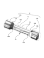
- FIG. 1 is an external perspective view of an electricity recovery engine according to an embodiment of the present invention.
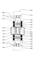
- FIG. 2 is a cross-sectional perspective view of the main part of the electricity recovery engine.
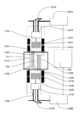
- FIG. 3 is a sectional view of the electricity recovery engine.
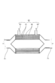
- FIG. 4 is a cross-sectional view showing an endothermic heat exchanger of the electricity recovery engine.
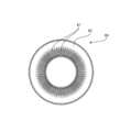
- FIG. 5 is a sectional view taken along line XX in FIG.
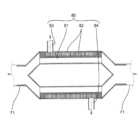
- FIG. 6 is a cross-sectional view showing another heat absorption heat exchanger of the electricity recovery engine according to this embodiment.
- FIG. 7 is a sectional view taken along line XX in FIG.
- FIG. 8 is a conceptual configuration diagram of an electricity recovery engine according to another embodiment of the present invention.
- FIG. 9 is a perspective view of an essential part of the electricity recovery engine.
- FIG. 9 is a perspective view of an essential part of the electricity recovery engine.
- FIG. 10 is a conceptual configuration diagram of an electricity recovery engine according to still another embodiment of the present invention.
- FIG. 11 is a conceptual configuration diagram of an electricity recovery engine according to still another embodiment of the present invention.
- FIG. 12 is a conceptual configuration diagram of an electricity recovery engine according to still another embodiment of the present invention.
- the electricity recovery engine includes one gas passage communicating with the expansion space of one displacer piston, the other gas passage communicating with the expansion space of the other displacer piston, and one gas.
- One Stirling engine and the other Stirling engine are connected and unitized by a heat exchanger that forms a passage and a heat medium passage for heating the other gas passage.
- a pair of Stirling engines are opposed to each other, a heat exchanger necessary for each Stirling engine is configured by one heat exchanger, and the pair of Stirling engines are connected by this heat exchanger.
- a simple configuration can be achieved.
- the second embodiment of the present invention uses oil or molten salt as a heat medium flowing in the heat medium passage in the electricity recovery engine according to the first embodiment. According to the present embodiment, by using oil or molten salt as a heat medium, sufficient heat recovery can be performed even when the heat transfer area is small, particularly when using low-temperature exhaust heat, and the heat exchanger The dead space, that is, the ineffective volume can be reduced.
- the pressure change can be increased, the illustrated power can be increased, and the power generation output can be increased.
- the heat exchanger by configuring the heat exchanger with a material with good thermal conductivity (SiC, copper material, etc.) once the heat energy of the low-temperature exhaust heat is stored in the heat medium, the heat exchanger loss can be reduced, Since the heat exchanger loss using the medium can be covered, an efficient electricity recovery engine can be realized.
- the heat exchanger is arranged on the piston head side outer peripheral portion of one displacer piston and on the piston head side of the other displacer piston. It is arranged in a ring shape on the outer periphery.
- an inlet for introducing the heat medium into the heat medium passage and an outlet for deriving the heat medium from the heat medium passage are heated. It arrange
- a small heat exchanger using oil or molten salt only on the outer periphery of the piston head, not between the piston heads the axial length of the displacer piston can be shortened.
- the heat medium includes an endothermic heat exchanger provided in the exhaust heat gas duct, an endothermic heat exchanger, and the heat exchanger.
- Circulating piping is provided.
- the heat of the exhaust heat gas duct is conveyed to the Stirling engine using oil or molten salt as a heat medium, so that the exhaust heat can be utilized with high thermal efficiency.
- the Stirling engine can be constructed without being affected by the arrangement of the exhaust heat gas duct, the workability is good. Therefore, it is possible to increase the degree of freedom in layout and cope with various exhaust heat sources even in high places and narrow places where it is difficult to install the exhaust gas duct.
- one gas passage is communicated with a regenerator of the other Stirling engine, and the other gas passage is connected to one Stirling engine.
- the regenerator In communication with the regenerator.
- the gas derived from the expansion space of one Stirling engine is led to the regenerator of the opposite Stirling engine without returning the gas to the regenerator of the same Stirling engine, and the expansion of the other Stirling engine is performed.
- the gas led out from the space is led to the regenerator of the opposite Stirling engine without returning it to the regenerator of the same Stirling engine, for example, it is not necessary to bend the gas passage into a U-shape and the gas has low flow resistance Since it can be a passage, pressure loss can be reduced and efficiency can be increased. Furthermore, compared with the case where there exists a bending part like a U-shaped part, reliability is improved, without thinning. Furthermore, even when thermal spraying (metal, ceramics) and coating are applied to the corrosive gas, since there is no bend, the adhesion strength between the corrosion-resistant film and the gas passage material is increased, Durability can be improved.
- the gas passage is disposed between a pair of opposing displacer pistons, and the flow direction of the gas flowing through the heat medium passage is determined. The direction is perpendicular to the axis of the displacer piston. According to this Embodiment, when it constructs in a flue like an exhaust heat gas duct, the exhaust heat of the gas which flows through a flue can be collect
- the gas passage is constituted by a plurality of straight pipes, and the respective straight pipes are arranged in an arc shape.
- a pair of Stirling engines are operated synchronously with a phase of 0 degrees.
- the vibration can be reduced by the synchronous operation of the pair of Stirling engines.
- a linear generator is attached to each power piston, and a control motor is attached to each displacer piston. is there.
- the present embodiment by using a linear generator, it is possible to perform highly efficient electricity recovery with less transmission loss compared to a rotary generator, and synchronization can be easily performed by each control motor.
- one power generator and one displacer piston are attached with one linear generator, and the other power piston and the other displacer.
- the other linear generator is attached to the piston.
- by using a linear generator it is possible to perform highly efficient electricity recovery with less transmission loss compared to a rotary generator and to keep the load of each linear generator constant. Can be easily performed.
- a rotary generator is attached to each power piston, and a control motor is attached to each displacer piston. It is. According to this embodiment, since the phases of the power piston and the displacer piston are fixed, synchronization can be easily performed.
- one power generator and one displacer piston are attached with one rotary generator, the other power piston and the other power piston.
- the displacer piston is provided with the other rotary generator. According to this embodiment, since the phases of the power piston and the displacer piston are fixed, synchronization can be easily performed.
- FIG. 1 is an external perspective view of the electricity recovery engine according to the present embodiment
- FIG. 2 is a cross-sectional perspective view of the main part of the electricity recovery engine
- FIG. 3 is a sectional view of the electricity recovery engine
- FIG. FIG. 5 is a sectional view showing the heat exchanger
- FIG. 5 is a sectional view taken along line XX in FIG.
- the sealed container 10 of the electricity recovery engine according to the present embodiment includes a cylindrical body 11 and container ends 12 ⁇ / b> A and 12 ⁇ / b> B disposed at both ends of the body 11.
- the container end portions 12 ⁇ / b> A and 12 ⁇ / b> B are formed in a cylindrical shape having a larger diameter than the body portion 11.
- a heat medium introduction port 13 for introducing the heat medium and a heat medium outlet port 14 for deriving the heat medium are attached to the outer peripheral surface of the central portion in the longitudinal direction of the body 11.
- cooling water inlets 15A and 15B for introducing cooling water and cooling water outlets 16A and 16B for leading cooling water are attached to the outer peripheral surfaces of both ends of the body portion 11, respectively.
- the respective container end portions 12A and 12B are provided with wiring connection portions 17A and 17B for taking out the wiring for the linear generator arranged inside the container end portions 12A and 12B.
- a central portion in the longitudinal direction of the body portion 11 is divided by an end plate 18 (the end plate 18 is omitted in FIG. 2), and a pair of cylinder portions 19A and 19B are formed inside the body portion 11 with the end plate 18 interposed therebetween.
- Displacer pistons 20A and 20B are disposed in the respective cylinder portions 19A and 19B.
- the displacer piston 20A of one Stirling engine and the displacer piston 20B of the other Stirling engine are arranged to face each other.
- Power pistons 21A and 21B are arranged coaxially in the axial direction of the displacer pistons 20A and 20B.
- the power pistons 21A and 21B are disposed in the container end portions 12A and 12B.
- Inner yokes 31A and 31B that reciprocate together with the power pistons 21A and 21B are fixed to the outer periphery of the power pistons 21A and 21B.
- Inner yoke 31A, 31B is comprised by the cylindrical shape, and magnet 32A, 32B is fixed to the outer periphery.
- Cylindrical outer yokes 33A and 33B are arranged on the outer periphery of the inner yokes 31A and 31B with a predetermined gap from the inner yokes 31A and 31B.
- Coils 34A and 34B are fixed to the inner peripheral sides of the outer yokes 33A and 33B.
- the coils 34A and 34B and the magnets 32A and 32B are arranged to face each other.
- Linear generators 30A and 30B are configured by inner yokes 31A and 31B having magnets 32A and 32B and outer yokes 33A and 33B having coils 34A and 34B.
- Regenerators 41A and 41B and coolers 42A and 42B are provided on the outer periphery of the displacer pistons 20A and 20B in the body portion 11.
- the regenerators 41A and 41B and the coolers 42A and 42B are configured in a ring shape.
- a cooling water inlet 15A and a cooling water outlet 16A are connected to the cooler 42A, and a cooling water inlet 15B and a cooling water outlet 16B are connected to the cooler 42B.
- the expansion space 22A of the displacer piston 20A is formed by the cylinder portion 19A, the end plate 18, and the piston head of the displacer piston 20A.
- the expansion space 22B of the displacer piston 20B is formed by the cylinder portion 19B, the end plate 18, and the piston head of the displacer piston 20B.
- the end plate 18 can be omitted.
- the expansion space 22A of one displacer piston 20A and the expansion space 22B of the other displacer piston 20B are a common expansion space.
- the heat exchanger 50 is a ring-shaped central portion in the longitudinal direction of the body portion 11 and includes an outer peripheral portion on the piston head side of one displacer piston 20A and an outer peripheral portion on the piston head side of the other displacer piston 20B. Is arranged.
- the coolers 42A and 42B are disposed at both ends of the trunk portion 11, and the regenerators 41A and 41B are disposed between the heat exchanger 50 and the coolers 42A and 42B.
- the heat exchanger 50 includes one gas passage 51A that communicates with the expansion space 22A of one displacer piston 20A, the other gas passage 51B that communicates with the expansion space 22B of the other displacer piston 20B, one gas passage 51A, A heat medium passage 52 for heating the other gas passage 51B is formed.
- the heat exchanger 50 is configured as a unit by connecting the one Stirling engine and the other Stirling engine by integrally configuring the one gas passage 51A and the other gas passage 51B. .
- the heat exchanger 50 is arranged in a ring shape on the outer periphery of the one displacer piston 20A on the piston head side and on the outer periphery of the other displacer piston 20B on the piston head side, and the heat medium passage 52 is a pair of opposed ones.
- the displacer pistons 20A and 20B are not arranged. Oil is used as the heat medium flowing through the heat medium passage 52. Further, when the exhaust heat temperature is high, a molten salt may be used as the heat medium.
- One gas passage 51A communicates with one regenerator 41A, one regenerator 41A communicates with one cooler 42A, and one cooler 42A communicates with the compression space 23A of one displacer piston 20A.
- the other gas passage 51B communicates with the other regenerator 41B, the other regenerator 41B communicates with the other cooler 42B, and the other cooler 42B communicates with the compression space 23B of the other displacer piston 20B.
- One end of the rod is composed of large-diameter rods 24A and 24B, and the other end of the rod is composed of small-diameter rods 25A and 25B.
- the large-diameter rods 24A and 24B are fixed to the displacer pistons 20A and 20B.
- Container edge part 12A, 12B accommodates power piston 21A, 21B and linear generator 30A, 30B inside.
- one Stirling engine is configured by the displacer piston 20A, the power piston 21A, the heat exchanger 50 as a heating unit, the regenerator 41A, and the cooler 42A, and the other Stirling engine is the displacer piston 20B, The power piston 21B, the heat exchanger 50 as a heating unit, a regenerator 41B, and a cooler 42B are included.
- the enclosed gas expands by heating in the heat exchanger 50 and moves the displacer pistons 20A and 20B away from the end plate 18 (end portion direction).
- the gas in the compression spaces 23A and 23B is compressed, and the power pistons 21A and 21B are moved in the end direction. Due to the movement of the power pistons 21A and 21B in the end direction, the gas passes from the expansion spaces 22A and 22B of the displacer pistons 20A and 20B through the heat exchanger 50, the regenerators 41A and 41B, and the coolers 42A and 42B.
- the power pistons 21A and 21B move in the central direction when the compression spaces 23A and 23B become low pressure due to the movement of the displacer pistons 20A and 20B in the direction close to the end plate 18 (center direction). Due to the movement of the power pistons 21A and 21B toward the center, the gas in the compression spaces 23A and 23B passes through the coolers 42A and 42B, the regenerators 41A and 41B, and the heat exchanger 50, and enters the expansion spaces 22A and 22B. Moving.
- the gas reciprocates between the expansion spaces 22A and 22B and the compression spaces 23A and 23B while performing expansion and contraction, thereby displacer piston 20A, While moving 20B, power piston 21A, 21B is moved. And electric power generation can be performed by movement of power piston 21A, 21B.
- the pair of Stirling engines according to the present embodiment are preferably operated synchronously.
- the heat absorption heat exchanger 60 is provided in the flue of the exhaust heat gas duct 71.
- the heat-absorbing heat exchanger 60 is constituted by a double pipe shell, and a plurality of tubes 61 for flowing exhaust gas are provided in the double pipe shell.
- the outer circumferential space 62 of the tube 61 serves as a heat medium passage, and the heat medium passage includes an inlet 63 and an outlet 64.
- the outer diameter of the double pipe shell is larger than that of the exhaust heat gas duct 71, and the total cross sectional area of the tube 61 is larger than the cross sectional area of the exhaust heat gas duct 71. Is made smaller.
- the introduction port 63 is arranged on the downstream side of the exhaust gas flow, and the outlet port 64 is arranged on the upstream side of the exhaust gas flow, so that the flow of the heat medium and the exhaust gas flow are opposed to each other.
- the inlet 63 is connected to the heat medium outlet 14 shown in FIGS. 1 to 3 by piping, and the outlet 64 is connected to the heat medium inlet 13 shown in FIGS. 1 to 3 by piping. Is circulated through the heat-absorbing heat exchanger 60 and the heat exchanger 50.
- FIGS. 6 is a cross-sectional view showing another heat absorption heat exchanger of the same electricity recovery engine
- FIG. 7 is a cross-sectional view taken along line XX in FIG.
- the heat absorption heat exchanger 80 is provided in the flue of the exhaust heat gas duct 71.
- the heat-absorbing heat exchanger 80 is constituted by a double pipe shell, and an exhaust gas passage space is formed in the inner periphery of the double pipe shell, and fins 81 are provided in the exhaust gas passage space.
- the fins 81 are constituted by a plurality of flat plates, and each flat plate is erected radially on the inner pipe with the pipe axis direction of the double pipe shell as the longitudinal direction.
- a spiral heat medium passage 82 is formed on the outer periphery of the double tube shell. If the heat transfer area in the exhaust gas passage space is sufficient, the exhaust gas passage space may be formed by through holes without providing the fins 81.
- the heat medium passage 82 includes an inlet 83 and an outlet 84.
- the outer diameter of the double pipe shell is larger than that of the exhaust heat gas duct 71, and the total cross-sectional area of the exhaust gas flow path between the fins 81 is larger than the cross-sectional area of the exhaust heat gas duct 71, thereby passing through the heat absorption heat exchanger 80.
- the flow resistance of exhaust gas is reduced.
- the introduction port 83 is disposed on the downstream side of the exhaust gas flow, and the outlet port 84 is disposed on the upstream side of the exhaust gas flow, so that the flow of the heat medium and the exhaust gas flow are opposed to each other.
- the inlet 83 is connected to the heat medium outlet 14 shown in FIGS. 1 to 3 through a pipe, and the outlet 84 is connected to the heat medium inlet 13 shown in FIGS. 1 to 3 through a pipe. Is circulated through the heat-absorbing heat exchanger 80 and the heat exchanger 50.
- FIG. 8 is a conceptual configuration diagram of the electricity recovery engine according to the present embodiment
- FIG. 9 is a perspective view of the main part of the electricity recovery engine.
- the displacer piston 120A of one Stirling engine and the displacer piston 120B of the other Stirling engine are arranged to face each other, and in the axial direction of the displacer pistons 120A, 120B, a power piston 121A, 121B is arranged on the same axis.
- Displacer pistons 120A and 120B are arranged in cylinder portions 119A and 119B.
- Linear power generators 130A and 130B are attached to the power pistons 121A and 121B.
- Regenerators 141A and 141B and coolers 142A and 142B are provided on the outer periphery of the displacer pistons 120A and 120B.
- the regenerators 141A and 141B and the coolers 142A and 142B are configured in a ring shape.
- Cooling water inlets 115A and 115B and cooling water outlets 116A and 116B are connected to the coolers 142A and 142B.
- the expansion space 122A of the displacer piston 120A is formed by the cylinder portion 119A, the end plate 118A, and the piston head of the displacer piston 120A.
- the expansion space 122B of the displacer piston 120B is formed by the cylinder portion 119B, the end plate 118B, and the piston head of the displacer piston 120B.
- the heat exchanger 150 is disposed between the end plate 118A of one displacer piston 120A and the end plate 118B of the other displacer piston 120B.
- the coolers 142A and 142B are disposed at the ends of the cylinder portions 119A and 119B, and the regenerators 141A and 141B are disposed between the heat exchanger 150 and the coolers 142A and 142B.
- the heat exchanger 150 includes one gas passage 151A communicating with the expansion space 122A of one displacer piston 120A, the other gas passage 151B communicating with the expansion space 122B of the other displacer piston 120B, one gas passage 151A, and A heat medium passage 152 for heating the other gas passage 151B is formed.
- the heat exchanger 150 is configured as a unit by connecting the one Stirling engine and the other Stirling engine by integrally configuring the one gas passage 151A and the other gas passage 151B.
- the heat medium passage 152 may be installed in a factory, or may directly use an exhaust gas passage or a heat exhaust duct mounted on a vehicle.
- the heat medium passage 152 has exhaust gas as a heat medium. Flowing.
- the gas passages 151A and 151B are disposed between a pair of opposing displacer pistons 120A and 120B, and the flow direction of the gas flowing through the heat medium passage 152 is orthogonal to the axis of the displacer pistons 120A and 120B. The direction.
- the gas passages 151 ⁇ / b> A and 151 ⁇ / b> B are disposed in the exhaust heat gas duct 171.
- the gas passages 151A and 151B are constituted by a plurality of straight pipes, and the respective straight pipes are arranged in an arc shape.
- one gas passage 151A communicates with the other regenerator 141B
- the other regenerator 141B communicates with the other cooler 142B
- the other cooler 142B is the other displacer piston. It communicates with the 120B compression space 123B.
- control motors 180A and 180B are attached to the displacer pistons 120A and 120B, respectively, and the pair of Stirling engines are synchronously operated with a phase of 0 degrees by the control motors 180A and 180B.
- the enclosed gas expands by heating in the heat exchanger 150 and moves the displacer pistons 120A and 120B away from the end plates 118A and 118B (end direction).
- the gas in the compression space 123A is compressed, and the power piston 121A is moved in the end direction. Due to the movement of the power piston 121A toward the end, the gas in the expansion space 122B of the other displacer piston 120B passes through the heat exchanger 150, the regenerator 141A, and the cooler 142A, and the displacer piston 120A and the power piston 121A. It moves to the compression space 123A between.
- the displacement of the compression space 123A by the movement of the displacer piston 120A in the direction (center direction) close to the end plate 118A causes the power piston 121A to move in the center direction.
- the gas in one compression space 123A passes through the cooler 142A, the regenerator 141A, and the heat exchanger 150 and moves to the expansion space 122B of the other displacer piston 120B.
- the gas in the compression space 123B is compressed by the movement of the other displacer piston 120B in the end direction, and the power piston 121B is moved in the end direction.
- the gas in the expansion space 122A of one displacer piston 120A passes through the heat exchanger 150, the regenerator 141B, and the cooler 142B, and the displacer piston 120B and the power piston 121B. It moves to the compression space 123B between. Then, the displacement of the compression space 123B due to the movement of the displacer piston 120B in the center direction causes the power piston 121B to move in the center direction. By the movement of the power piston 121B toward the center, the gas in the other compression space 123B passes through the cooler 142B, the regenerator 141B, and the heat exchanger 150, and moves to the expansion space 122A of the one displacer piston 120A. .
- the gas reciprocates between the expansion spaces 22A and 22B and the compression spaces 23A and 23B while performing expansion and contraction, thereby displacer piston 20A, While moving 20B, power piston 21A, 21B is moved. And electric power generation can be performed by movement of power piston 21A, 21B.
- the gas led out from the expansion space 122A of one Stirling engine is led to the compression space 123B of the other Stirling engine facing the other Stirling engine without returning to the compression space 123A of the same Stirling engine.
- the gas passage can have a low flow resistance, and the efficiency can be increased and the gas passages 151A and 151B can be configured by straight pipes. Therefore, the durability can be improved as compared with the case where there is a bent portion such as a U-shaped portion. Can be improved.
- FIG. 10 to 12 are conceptual configuration diagrams of an electricity recovery engine according to different embodiments.
- components having the same functions as those in FIG.
- the reciprocating motion of the displacer pistons 120A and 120B is electrically generated from the power pistons 121A and 121B attached to the linear generators 130A and 130B.
- the synchronous control part 190 which performs load control of the linear generators 130A and 130B is provided.
- rotary generators 200A and 200B are provided via crank mechanisms 201A and 201B instead of the linear generators 130A and 130B in the embodiment shown in FIG.
- displacer pistons 120A and 120B are connected to rotary generators 200A and 200B via crank mechanisms 201A and 201B instead of the control motors 180A and 180B in the embodiment shown in FIG.
- a synchronous control unit 190 that performs load control of the rotary generators 200A and 200B is provided.
- the electricity recovery engine according to the embodiment shown in FIG. 10 to FIG. 12 causes a pair of Stirling engines to operate synchronously at a phase of 0 degrees depending on the respective configurations.
- the configuration for synchronous operation shown in FIGS. 8 and 9 and the configuration for synchronous operation shown in FIGS. 10 to 12 can be applied to the embodiments shown in FIGS. .
- the electricity recovery engine communicates with one gas passage 51A, 151A communicating with the expansion spaces 22A, 122A of one displacer piston 20A, 120A and with expansion spaces 22B, 122B of the other displacer pistons 20B, 120B.
- the heat exchangers 50 and 150 that form the other gas passages 51B and 151B, the one gas passages 51A and 151A, and the heat medium passages 52 and 152 that heat the other gas passages 51B and 151B are combined with one Stirling engine. Since the other Stirling engine is connected and unitized, a simple configuration can be obtained as compared with two separate Stirling engines.
- the heat exchangers 50 and 150 can be arranged in the flue and the Stirling engine can be projected from the flue, so that the exhaust heat gas duct Good workability in flues.
- the electricity recovery engine according to the present embodiment uses oil or molten salt as the heat medium flowing in the heat medium passage 52, so that sufficient heat recovery is possible even when the heat transfer area is small, particularly when using low-temperature exhaust heat. This can be done and the dead space of the heat exchanger can be reduced.
- the heat exchanger 50 is arranged in a ring shape on the outer periphery of the one displacer piston 20A on the piston head side and on the outer periphery of the other displacer piston 20B on the piston head side.
- the thermal efficiency can be increased.
- the heat medium passage 52 is not disposed between the pair of opposing displacer pistons 20A and 20B, and the introduction port 13 for introducing the heat medium into the heat medium passage 52, and the heat medium passage.
- the electricity recovery engine includes heat absorption heat exchangers 60 and 80 provided in the exhaust heat gas duct 71, and a pipe through which a heat medium circulates between the heat absorption heat exchangers 60 and 80 and the heat exchanger 50.
- exhaust heat can be used with high thermal efficiency, and the Stirling engine can be constructed without being affected by the arrangement of the exhaust heat gas duct, so that the workability is good.
- one gas passage 151A is communicated with the regenerator 141B of the other Stirling engine, and the other gas passage 151B is communicated with the regenerator 141A of one Stirling engine.
- the gas passage 150 is disposed between a pair of opposing displacer pistons 120A and 120B, and the flow direction of the gas flowing through the heat medium passage 152 is orthogonal to the axis of the displacer pistons 120A and 120B.
- the gas passages 151A and 151B are constituted by a plurality of straight pipes, and the respective straight pipes are arranged in a ring shape, so that the gas flow flowing through the flue such as the exhaust heat gas duct 171 can be prevented.
- the pair of Stirling engines can be operated synchronously with a phase of 0 degrees, so that the vibration can be reduced by the synchronous operation of the pair of Stirling engines.
- the electricity recovery engine according to the present embodiment is rotated by attaching linear generators 130A and 130B to the power pistons 120A and 120B, respectively, and attaching control motors 180A and 180B to the displacer pistons 120A and 120B, respectively.
- the electric power generators 200A and 200B there is less transmission loss and highly efficient electricity recovery can be performed, and synchronization can be easily performed by the respective control motors.
- one power generator 121A and one displacer piston 120A have one linear generator 130A attached, and the other power piston 121B and the other displacer piston 120B have the other linear generator 130B.
- By attaching the linear generators 130A and 130B it is possible to perform highly efficient electricity recovery with less transmission loss compared to the rotary generators 200A and 200B, and keep the load of each linear generator constant. Thus, synchronization can be easily performed.
- rotary power generators 200A and 200B are attached to the power pistons 121A and 121B, respectively, and control motors 180A and 180B are attached to the displacer pistons 120A and 120B, respectively.
- one rotary generator 200A is attached to one power piston 121A and one displacer piston 120A
- the other rotary power generator is attached to the other power piston 121B and the other displacer piston 120B.
- the machine 200B is attached.
- the phases of power pistons 121A and 121B and displacer pistons 120A and 120B are fixed, synchronization can be easily performed.
- the electricity recovery engine of the present invention can be applied not only to factory exhaust heat but also to exhaust heat of engines such as automobiles and ships.
Landscapes
- Engineering & Computer Science (AREA)
- Chemical & Material Sciences (AREA)
- Combustion & Propulsion (AREA)
- Mechanical Engineering (AREA)
- General Engineering & Computer Science (AREA)
- Engine Equipment That Uses Special Cycles (AREA)
Abstract
L'invention concerne un moteur destiné à une récupération électrique, caractérisé en ce qu'un moteur Stirling et un autre moteur Stirling sont réunis en étant couplés l'un à l'autre, à l'aide d'un échangeur thermique (50) constitué d'un premier passage de gaz (51A) qui communique avec un espace de dilatation (22A) d'un premier piston de déplacement (20A), d'un autre passage de gaz (51B) qui communique avec un espace de dilatation (22B) de l'autre piston de déplacement (20B) et d'un passage de fluide de chauffage (52) qui chauffe le passage de gaz (51A) et le passage de gaz (51B). Dans le moteur destiné à la récupération électrique, même un rejet thermique basse température d'environ 200 °C qui a été évacué à partir d'un conduit d'une usine peut être converti efficacement en énergie électrique par un échangeur thermique afin de générer un rejet thermique basse température présentant une performance de transfert thermique suffisante.
Applications Claiming Priority (2)
| Application Number | Priority Date | Filing Date | Title |
|---|---|---|---|
| JP2009-136783 | 2009-06-08 | ||
| JP2009136783A JP5365352B2 (ja) | 2009-06-08 | 2009-06-08 | 電気回収エンジン |
Publications (1)
| Publication Number | Publication Date |
|---|---|
| WO2010143418A1 true WO2010143418A1 (fr) | 2010-12-16 |
Family
ID=43308681
Family Applications (1)
| Application Number | Title | Priority Date | Filing Date |
|---|---|---|---|
| PCT/JP2010/003816 Ceased WO2010143418A1 (fr) | 2009-06-08 | 2010-06-08 | Moteur destiné à une récupération électrique |
Country Status (2)
| Country | Link |
|---|---|
| JP (1) | JP5365352B2 (fr) |
| WO (1) | WO2010143418A1 (fr) |
Cited By (2)
| Publication number | Priority date | Publication date | Assignee | Title |
|---|---|---|---|---|
| JP3188818U (ja) * | 2013-09-12 | 2014-02-13 | 志村 征男 | スターリングエンジン |
| CN114320656A (zh) * | 2021-12-10 | 2022-04-12 | 兰州空间技术物理研究所 | 一种应用于斯特林发电机的加热器组件 |
Families Citing this family (1)
| Publication number | Priority date | Publication date | Assignee | Title |
|---|---|---|---|---|
| JP2014031726A (ja) * | 2012-08-01 | 2014-02-20 | Hidemi Kurita | スターリングエンジンの駆動制御方法 |
Citations (5)
| Publication number | Priority date | Publication date | Assignee | Title |
|---|---|---|---|---|
| JPS61261647A (ja) * | 1985-05-15 | 1986-11-19 | Kawasaki Heavy Ind Ltd | フリ−ピストン型スタ−リング機関 |
| JP2001207909A (ja) * | 2000-01-24 | 2001-08-03 | Sakushiyon Gas Kikan Seisakusho:Kk | スターリングサイクルおよび熱交換器 |
| JP2004138064A (ja) * | 2002-10-15 | 2004-05-13 | Enerlyt Potsdam Gmbh | 2個の可動部材を有する2サイクルスターリングエンジン |
| JP2007270789A (ja) * | 2006-03-31 | 2007-10-18 | Estir:Kk | スターリングエンジン |
| JP2009047152A (ja) * | 2007-08-21 | 2009-03-05 | Thermo Giken Kk | フリーピストン型スターリングサイクルサイクル機関 |
-
2009
- 2009-06-08 JP JP2009136783A patent/JP5365352B2/ja not_active Expired - Fee Related
-
2010
- 2010-06-08 WO PCT/JP2010/003816 patent/WO2010143418A1/fr not_active Ceased
Patent Citations (5)
| Publication number | Priority date | Publication date | Assignee | Title |
|---|---|---|---|---|
| JPS61261647A (ja) * | 1985-05-15 | 1986-11-19 | Kawasaki Heavy Ind Ltd | フリ−ピストン型スタ−リング機関 |
| JP2001207909A (ja) * | 2000-01-24 | 2001-08-03 | Sakushiyon Gas Kikan Seisakusho:Kk | スターリングサイクルおよび熱交換器 |
| JP2004138064A (ja) * | 2002-10-15 | 2004-05-13 | Enerlyt Potsdam Gmbh | 2個の可動部材を有する2サイクルスターリングエンジン |
| JP2007270789A (ja) * | 2006-03-31 | 2007-10-18 | Estir:Kk | スターリングエンジン |
| JP2009047152A (ja) * | 2007-08-21 | 2009-03-05 | Thermo Giken Kk | フリーピストン型スターリングサイクルサイクル機関 |
Cited By (2)
| Publication number | Priority date | Publication date | Assignee | Title |
|---|---|---|---|---|
| JP3188818U (ja) * | 2013-09-12 | 2014-02-13 | 志村 征男 | スターリングエンジン |
| CN114320656A (zh) * | 2021-12-10 | 2022-04-12 | 兰州空间技术物理研究所 | 一种应用于斯特林发电机的加热器组件 |
Also Published As
| Publication number | Publication date |
|---|---|
| JP5365352B2 (ja) | 2013-12-11 |
| JP2010281294A (ja) | 2010-12-16 |
Similar Documents
| Publication | Publication Date | Title |
|---|---|---|
| CN103114941B (zh) | 一种同时利用高低温热源的自由活塞斯特林发动机系统 | |
| US7891184B2 (en) | 4-cycle stirling machine with two double-piston units | |
| CN102734975B (zh) | 一种双作用热驱动行波热声制冷系统 | |
| CN106194358B (zh) | 多级热声发电机组及具有该机组的多级回热式制冷系统 | |
| RU2008135296A (ru) | Генерирование электричества в турбомашине | |
| CN102232142A (zh) | 热引擎 | |
| JP2012198014A (ja) | スターリングエンジンを用いた熱交換器とそれに関連する方法 | |
| CN104653330B (zh) | 一种冷源脉管发动机和基于冷源脉管发动机的发电装置 | |
| JP5365352B2 (ja) | 電気回収エンジン | |
| CN110878722A (zh) | 一种采用环形燃烧器提供热量的对置式自由活塞斯特林发电机系统 | |
| JP2009236456A (ja) | パルス管型蓄熱機関 | |
| US20200149494A1 (en) | Double-acting stirling engines with optimal parameters and waveforms | |
| US8640453B2 (en) | Heat engine | |
| CN101283176A (zh) | 具有两个双活塞单元的4循环斯特林机器 | |
| CN110206657B (zh) | 一种热滞后型自由活塞斯特林发电机 | |
| US8096118B2 (en) | Engine for utilizing thermal energy to generate electricity | |
| JP2006200431A (ja) | エンジンシステム | |
| CN103758715B (zh) | 热声热机系统 | |
| CN116838496B (zh) | 分布式斯特林发电系统 | |
| CN102562357A (zh) | 一种中心轴椭圆转子斯特林发动机 | |
| JP4342566B2 (ja) | 熱機関 | |
| JP2025021694A (ja) | スターリングエンジン | |
| CN210564803U (zh) | 一种热滞后型自由活塞斯特林发电机 | |
| CN110971143B (zh) | 一种可实现回热的静止式热磁发电装置 | |
| CN210178483U (zh) | 一种自由活塞斯特林发动机 |
Legal Events
| Date | Code | Title | Description |
|---|---|---|---|
| 121 | Ep: the epo has been informed by wipo that ep was designated in this application |
Ref document number: 10785950 Country of ref document: EP Kind code of ref document: A1 |
|
| NENP | Non-entry into the national phase |
Ref country code: DE |
|
| 122 | Ep: pct application non-entry in european phase |
Ref document number: 10785950 Country of ref document: EP Kind code of ref document: A1 |