WO2010137545A1 - 携帯端末およびスライド制御プログラム - Google Patents
携帯端末およびスライド制御プログラム Download PDFInfo
- Publication number
- WO2010137545A1 WO2010137545A1 PCT/JP2010/058713 JP2010058713W WO2010137545A1 WO 2010137545 A1 WO2010137545 A1 WO 2010137545A1 JP 2010058713 W JP2010058713 W JP 2010058713W WO 2010137545 A1 WO2010137545 A1 WO 2010137545A1
- Authority
- WO
- WIPO (PCT)
- Prior art keywords
- display
- state
- incoming call
- mobile terminal
- call
- Prior art date
- Legal status (The legal status is an assumption and is not a legal conclusion. Google has not performed a legal analysis and makes no representation as to the accuracy of the status listed.)
- Ceased
Links
Images











Classifications
-
- H—ELECTRICITY
- H04—ELECTRIC COMMUNICATION TECHNIQUE
- H04M—TELEPHONIC COMMUNICATION
- H04M1/00—Substation equipment, e.g. for use by subscribers
- H04M1/02—Constructional features of telephone sets
- H04M1/0202—Portable telephone sets, e.g. cordless phones, mobile phones or bar type handsets
- H04M1/0206—Portable telephones comprising a plurality of mechanically joined movable body parts, e.g. hinged housings
- H04M1/0208—Portable telephones comprising a plurality of mechanically joined movable body parts, e.g. hinged housings characterized by the relative motions of the body parts
- H04M1/0235—Slidable or telescopic telephones, i.e. with a relative translation movement of the body parts; Telephones using a combination of translation and other relative motions of the body parts
- H04M1/0237—Sliding mechanism with one degree of freedom
-
- H—ELECTRICITY
- H04—ELECTRIC COMMUNICATION TECHNIQUE
- H04M—TELEPHONIC COMMUNICATION
- H04M1/00—Substation equipment, e.g. for use by subscribers
- H04M1/57—Arrangements for indicating or recording the number of the calling subscriber at the called subscriber's set
-
- H—ELECTRICITY
- H04—ELECTRIC COMMUNICATION TECHNIQUE
- H04M—TELEPHONIC COMMUNICATION
- H04M2250/00—Details of telephonic subscriber devices
- H04M2250/16—Details of telephonic subscriber devices including more than one display unit
-
- H—ELECTRICITY
- H04—ELECTRIC COMMUNICATION TECHNIQUE
- H04M—TELEPHONIC COMMUNICATION
- H04M2250/00—Details of telephonic subscriber devices
- H04M2250/22—Details of telephonic subscriber devices including a touch pad, a touch sensor or a touch detector
Definitions
- the present invention relates to a mobile terminal, and more particularly to a mobile terminal in which a plurality of casings are slidably connected.
- Non-Patent Document 1 a portable terminal in which a plurality of casings are slidably connected is known, and an example of this type of device is disclosed in Non-Patent Document 1.
- the slide-type mobile phone according to the background art is provided on the upper casing so that the display is exposed, and the power of the display is turned off in the standby state.
- the display and the backlight of the display are turned on, and predetermined information is displayed on the display. Is done.
- Patent Document 1 discloses a slide-type mobile terminal. This portable terminal has a large liquid crystal display unit and a small liquid crystal display unit in a lower housing. In the shortened state (closed state), since the large liquid crystal display unit is provided at a position covered by the other housing, only the small liquid crystal display unit is exposed.
- Non-Patent Document 1 the display and the backlight are turned on only by performing a simple operation for checking the time, so that the mobile phone in comparison with the foldable mobile phone having a sub display is used. , Power consumption will increase.
- the main object of the present invention is to provide a novel portable terminal.
- Another object of the present invention is to provide a portable terminal capable of suppressing power consumption.
- Another object of the present invention is to provide a portable terminal capable of protecting privacy.
- Still another object of the present invention is to provide a portable terminal and a slide control program that can accurately provide information required by a user.
- This invention employs the following configuration in order to solve the above problems.
- the reference numerals in parentheses, supplementary explanations, and the like indicate the corresponding relationship with the embodiments described in order to help understanding of the present invention, and do not limit the present invention.
- 1st invention 1st housing
- the first casing (C1) and the second casing (C2) are formed in a plate shape, for example.
- the first housing is provided with a first display unit (26) such as an LCD monitor.
- the first housing and the second housing are slidably coupled by a slide mechanism (50) including a spring (56), for example.
- the 2nd display part (34) in which an organic EL panel etc. is used is provided in the position exposed when a slide operation is carried out without exposing at the normal time (closed state).
- the user can confirm predetermined information such as time on the second display unit by performing a slide operation as a simple operation.
- the power consumption of a portable terminal can be suppressed by employ
- the first display unit is in a display state in consideration of privacy. Therefore, the privacy of the user can be protected by displaying predetermined information only when a slide operation is performed. Furthermore, the privacy protection effect is further enhanced by adopting a second display unit that is smaller than the first display unit.
- the second invention is dependent on the first invention, the first housing is connected in a state of being stacked on the second housing, and the second display unit is provided in the second housing.
- the first housing is laminated on the second housing, for example, like a slide type mobile terminal.
- the 2nd display part is provided in the 2nd case so that it may be inserted between the 1st case and the 2nd case, for example.
- the first display unit and the second display unit are provided at positions that can be simultaneously confirmed when a slide operation is performed, convenience for the user is improved.
- a third invention is dependent on the first invention or the second invention, and is a determination unit that determines whether or not a specific state is detected, a detection unit that detects a slide operation, and a slide state that is determined as a specific state.
- the information display part which displays information on a 2nd display part when is detected is further provided.
- the determination unit (20, S1, S27, S45, S49) specifies a state in which the mobile terminal is frequently used in a specific state (incoming call state, incoming call state, standby state).
- a detection part (20, 40, 42, S41) detects a slide operation from the value which a magnetic sensor outputs, for example.
- an information display part (20, S71, S111, S155, S183) displays the information which should be notified to a user on a 2nd display part corresponding to a specific state.
- information required by the user can be accurately provided according to the situation in which the mobile terminal is used.
- the fourth invention is dependent on the third invention, and the information is displayed by the open state detection unit that detects whether the first housing and the second housing are in the open state, and the information display unit.
- a first processing unit is further provided for executing a predetermined process when the state is detected.
- the open state detector (20, 42, 44) detects the open state using, for example, a magnetic sensor and a magnet.
- the first processing unit (20, S79, S119, S159) executes, as a predetermined process, a process that is highly likely to be executed in the specific state.
- the user can execute a predetermined process by continuing the slide operation after confirming the information displayed on the second display unit.
- a fifth invention is dependent on the fourth invention, the specific state includes an incoming call state, the determination unit includes an incoming call determination unit that determines whether the incoming call state is present, and the first processing unit includes: A call processing unit that starts a call process when it is determined that the call is in an incoming state is included.
- the incoming call determination unit (20, S1, S45) determines whether the incoming call state is included in the specific state.
- the call processing unit (20, S79) When the call processing unit (20, S79) is in the open state, the call processing unit (20, S79) establishes a call-capable state with the other party.
- the user can start a call with the other party after confirming the information of the other party.
- a sixth invention is according to the fourth invention, the specific state includes an incoming mail state, the determination unit further includes an incoming determination unit that determines whether the incoming state is present, and the first processing unit includes: A mail display unit that displays the content of the mail on the first display unit when it is determined that the incoming state is received.
- the incoming call determination unit (20, S27, S49) determines whether the incoming state is included in the specific state.
- a mail display part (20, S119) will display the content (text) of a mail on a 1st display part, if it is made into an open state.
- the user can display the text of the mail after confirming the sender of the mail.
- a seventh invention is dependent on the first invention, and in a touch reaction area provided in the second display unit, a touch operation detection unit that detects a touch operation in the touch reaction area, and obtains information of a process to be executed And a symbol display unit for displaying a symbol on the second display unit based on the information of the processing acquired by the acquisition unit, and when a touch operation is included in the symbol display range, a predetermined process is executed. 2 processing part is further provided.
- the touch operation detection unit (20, 38) includes, for example, a touch panel (38) provided on the surface of the second display unit.
- the touch operation detection unit detects a touch operation in a touch reaction area corresponding to the display area of the second display unit.
- the acquisition unit (20, S211) acquires, for example, a function ID of a process to be executed (music player function).
- the symbol display unit (20, S215) displays a symbol representing the touch key on the second display unit, for example, based on the acquired function ID.
- the second processing unit (20, S221) executes a predetermined process different from that of the first processing unit in response to a touch operation included in the symbol display range, that is, a touch key operation.
- touch keys corresponding to various functions executed on the mobile terminal can be displayed on the second display unit.
- the developer of the mobile terminal can effectively use the position where the second display unit is provided in the mobile terminal in which the arrangement of the operation keys is limited.
- the touch key is displayed according to the function to be executed, the user can easily perform an input operation for the function to be executed.
- a determination unit for determining whether or not the processor (20) of the portable terminal (10) of claim 1 is in a specific state (incoming call state, incoming call state, standby state).
- S43, S47 a detection unit (S41) that detects a slide operation
- an information display unit S71, S111, S153
- the power consumption of the portable terminal can be suppressed by displaying predetermined information on the display unit with low power consumption.
- the information required by the user can be provided accurately.
- FIG. 1 is a block diagram showing an electrical configuration of a portable terminal according to an embodiment of the present invention.
- FIG. 2 is an illustrative view showing one example of an appearance of the mobile terminal shown in FIG.
- FIG. 3 is an illustrative view showing one example of an appearance of a slide mechanism included in the portable terminal shown in FIG. 4 is an illustrative view showing another example of the appearance of the slide mechanism shown in FIG.
- FIG. 5 is an illustrative view showing one example of the operation of the slide function shown in FIG.
- FIG. 6 is an illustrative view showing a display example of the first display and the second display when a slide operation is performed in the mobile terminal having the appearance shown in FIG. FIG.
- FIG. 7 is an illustrative view showing another display example of the first display and the second display when a slide operation is performed in the mobile terminal having the appearance shown in FIG.
- FIG. 8 is an illustrative view showing another display example of the first display and the second display when a slide operation is performed in the mobile terminal having the appearance shown in FIG.
- FIG. 9 is an illustrative view showing still another display example of the first display and the second display when the sliding operation is performed in the mobile terminal having the appearance shown in FIG.
- FIG. 10 is an illustrative view showing one example of a memory map of the RAM shown in FIG.
- FIG. 11 is an illustrative view showing one example of a data storage area shown in FIG. FIG.
- FIG. 12 is a flowchart showing the incoming call processing of the CPU shown in FIG.
- FIG. 13 is a flowchart showing the incoming call processing of the CPU shown in FIG.
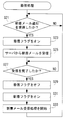
- FIG. 14 is a flowchart showing the slide control processing of the CPU shown in FIG.
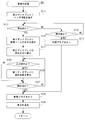
- FIG. 15 is a flowchart showing processing during the incoming call of the CPU shown in FIG.
- FIG. 16 is a flowchart showing the incoming call processing of the CPU shown in FIG.
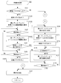
- FIG. 17 is a flowchart showing a part of standby processing of the CPU shown in FIG.
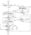
- FIG. 18 is another part of the standby processing of the CPU shown in FIG. 1, and is a flowchart subsequent to FIG.
- FIG. 19 is a flowchart showing the touch key control processing of the CPU shown in FIG.
- the mobile terminal 10 includes a CPU (also called a processor or a computer) 20 and a key input device 22 that is an input device.
- the CPU 20 controls the radio communication circuit 14 corresponding to the CDMA system and outputs a call signal.
- the output call signal is transmitted from the antenna 12 and transmitted to the mobile communication network including the base station.
- a call ready state is established.
- the CPU 20 controls the wireless communication circuit 14 to transmit a call termination signal to the other party. Then, after transmitting the call end signal, the CPU 20 ends the call process. Also, when the call end signal is received from the call partner first, the CPU 20 ends the call process. Furthermore, the CPU 20 also ends the call process when a call end signal is received from the mobile communication network regardless of the call partner.
- the wireless communication circuit 14 When the call signal from the other party is caught by the antenna 12 while the mobile terminal 10 is activated, the wireless communication circuit 14 notifies the CPU 20 of the incoming call.
- the CPU 20 turns on the LED 46 and outputs an incoming call sound from a speaker (not shown). Note that the CPU 20 may vibrate the mobile terminal 10 by driving (rotating) a motor (not shown) to notify the user of an incoming call.
- the CPU 20 controls the first display driver 24 or the second display driver 32 to display on the first display 26 or the second display 34 the source information transmitted from the call partner together with the call signal.
- the following processing is executed in the call ready state.
- the modulated audio signal (high frequency signal) sent from the other party is received by the antenna 12.
- the received modulated audio signal is subjected to demodulation processing and decoding processing by the wireless communication circuit 14.
- the obtained received voice signal is output from the speaker 18.
- the transmission voice signal captured by the microphone 16 is subjected to encoding processing and modulation processing by the wireless communication circuit 14.
- the generated modulated audio signal is transmitted to the other party using the antenna 12 as described above.
- the touch panel 38 is a pointing device for instructing an arbitrary position within the screen of the second display 34.
- the touch panel 38 When the touch panel 38 is operated by pressing, stroking, or touching the upper surface with a finger, the touch panel 38 detects the operation.
- the touch panel control circuit 36 specifies the position of the finger and outputs coordinate data of the operated position to the CPU 20. That is, the user can input an operation direction, a figure, or the like to the mobile terminal 10 by pressing, stroking, or touching the upper surface of the touch panel 38 with a finger.
- the touch panel 38 is a method called a capacitance method that detects a change in capacitance between electrodes generated when a finger approaches the surface of the touch panel 38, and one or more fingers touch the touch panel 38. Detect that. Specifically, the touch panel 38 employs a projection-type capacitance method that detects a change in capacitance between electrodes that occurs when a finger approaches a transparent film on which an electrode pattern is formed. Yes. As the detection method, a surface type capacitance method may be employed, or a resistance film method, an ultrasonic method, an infrared method, an electromagnetic induction method, or the like may be used.
- touch an operation in which the user touches the upper surface of the touch panel 38 with a finger
- release the operation of releasing the finger from the touch panel 38
- touch points The coordinates indicated by the touch
- release points The coordinates indicated by the release
- touch and release an operation in which the user touches the upper surface of the touch panel 38 and subsequently releases it.
- touch operations operations such as touch, release, and touch-and-release performed on the touch panel 38 are generally referred to as “touch operations”.
- the touch point is the barycentric coordinate of the area of the finger touching the touch panel 38.
- a dedicated touch pen or the like may be provided to perform a touch operation.
- the origin of the display coordinates of the second display 34 and the touch position coordinates of the touch panel 38 is the upper left corner. That is, the abscissa increases from the upper left corner toward the upper right corner, and the ordinate increases from the upper left corner toward the lower left corner.
- the CPU 20 and the touch panel 38 function as a touch operation detection unit.
- the mobile terminal 10 has a mail function, and can perform data communication with a mail server (not shown) to send and receive mail.
- a mail server (not shown) to send and receive mail.
- the antenna 12 and the wireless communication circuit 14 function as a communication unit, and a mail server or the like is connected to a network by wire or wireless.
- the mobile terminal 10 has a music player function for managing and playing back music data stored in the RAM 30. The user can enjoy music using the mobile terminal 10 when the music data is played back.
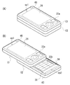
- FIG. 2A is an illustrative view showing an appearance of the mobile terminal 10 in a closed state
- FIG. 2B is an illustrative view showing an appearance of the mobile terminal 10 in an open state
- the mobile terminal 10 includes a first case C1 (first housing) and a second case C2 (second housing) each formed in a plate shape.
- the first case C1 and the second case C2 have substantially the same thickness, and the first case C1 is stacked on the second case C2 (stacked state), and the slide mechanism 50 (FIG. 3). Link).
- the first case C1 can slide in the length direction of the second case C2.
- the antenna 12 is built in the first case C1 or the second case C2, and is not shown in FIGS. 2 (A) and 2 (B).
- the microphone 16 (not shown) is built in the second case C2, and the opening OP2 leading to the built-in microphone 16 is provided on one upper surface of the second case C2 in the length direction.
- the speaker 18 (not shown) is built in the first case C1, and the opening OP1 leading to the built-in speaker 18 is provided on one upper surface of the first case C1 in the length direction.
- the key input device 22 includes a first key group 22a including a plurality of keys and a second key group 22b.
- the first key group 22a includes a direction key, a call key, an end key, a menu key, and a confirmation key, and is provided on the upper surface of the first case C1.
- the second key group 22b is composed of numeric keys 0 to 9 and the like, and is provided on the upper surface of the second case C2.
- the first display 26 is attached such that the monitor screen is exposed on the upper surface of the first case C1.
- the second display 34 is attached so that the monitor screen is exposed on the upper surface of the second case C2.
- a touch panel 38 is provided on the surface of the second display 34.
- LED46 is provided so that a light emission part may be exposed to one main surface of the length direction of 1st case C1.
- the user can operate the number keys 0 to 9 to input a telephone number and perform a call operation using the call key. Then, the user performs a call end operation using the call end key. Further, the user can display a menu screen by operating the menu key, and can select an arbitrary menu using the direction key. Then, the user can confirm the selected menu by operating the confirmation key.
- the user turns on / off the mobile terminal 10 by pressing and holding the end call key.
- the area of the second display 34 is smaller than that of the first display 26. Therefore, the power consumption of the second display 34 is smaller than the power consumption of the first display 26.
- the first magnetic sensor 40 is built in one side of the second case C2 in the length direction.
- the magnet 42 is built in the other side in the length direction of the first case C1 so as to be in a state closest to the first magnetic sensor 40 in the closed state shown in FIG.
- the second magnetic sensor 44 is built in the vicinity of the center of the second case C2 so as to be in a state closest to the magnet 42 in the open state shown in FIG.
- the first magnetic sensor 40 that detects the closed state of the mobile terminal 10 outputs a maximum value in the state shown in FIG.
- the second magnetic sensor 44 that detects the open state of the mobile terminal 10 outputs a maximum value in the state shown in FIG. That is, the CPU 20 detects the closed state when the first magnetic sensor 40 outputs the maximum value, and detects the open state when the second magnetic sensor 44 outputs the maximum value.
- a state where each of the first magnetic sensor 40 and the second magnetic sensor 44 does not output the maximum value is referred to as a “slide state”.
- the mobile terminal 10 transitions from the closed state to the slide state. Then, when the user further slides the first case C1, the portable terminal 10 transitions from the slide state to the open state.
- the second display 34 is not exposed in the normal state (closed state) but is provided at a position where it is exposed when a slide operation is performed.
- the first case C1 and the second case C2 are electrically connected by a flexible harness that is not affected by the slide.
- reference numerals of the first key group 22a, the second key group 22b, the first display 26, the second display 34, the touch panel 38, the first magnetic sensor 40, the LED 46, the opening OP1 and the opening OP2 are used. It may be omitted for simplicity.
- the CPU 20, the first magnetic sensor 40, and the magnet 42 function as a closed state detection unit
- the CPU 20, the magnet 42, and the second magnetic sensor 44 function as an open state detection unit.
- FIG. 3 is an illustrative view showing the appearance of the front surface of the slide mechanism 50
- FIG. 4 is an illustrative view showing the appearance of the back surface of the slide mechanism. 3 and 4 also show the external appearance of the first case C1 and the second case C2 in order to clarify the relationship between the slide mechanism 50 and the first case C1 and the second case C2.
- the slide mechanism 50 includes a first plate 52, a second plate 54, and a spring 56 that functions as a holding portion.
- the slide mechanism 50 is located between the first case C1 and the second case C2, the first plate 52 is connected to the upper surface of the second case C2, and the second plate 54 is connected to the lower surface of the first case C1. Is done.
- the first plate 52 is combined so as to slide with respect to the second plate 54. That is, as the first plate 52 slides with respect to the second plate 54, the first case C1 slides with respect to the second case C2.
- first plate 52 and the second plate 54 may be connected to the first case C1 and the second case C2 by being fixed by screws, or may be concave and convex. You may connect by fitting with a part.
- the spring 56 that holds the open or closed state of the mobile terminal 10 will be described in detail with reference to FIGS.
- the spring 56 included in the slide mechanism 50 holds the open state or the closed state of the mobile terminal 10 and assists the slide operation with respect to the first case C1 or the second case C2.
- a certain amount of slide amount in the present embodiment is a half of the moving distance when the first case C1 is slid from the closed state to the open state.
- the mobile terminal 10 is returned from the slide state to the closed state.
- the slide is assisted by one spring, but the slide may be assisted by using two or more springs.
- a coil spring is used as the spring 56, but other types of springs such as a leaf spring may be used.
- the mobile terminal 10 has a power saving function, and the user can set the power saving mode for the mobile terminal 10.
- the power of the first display 26 is turned off in a frequently used state (specific state) such as an incoming call state, an incoming mail state, and a standby state.
- the portable terminal 10 in the power saving mode only receives notification information of incoming calls and incoming mail, and predetermined information such as portable terminal information (time and remaining battery capacity) when a slide operation is performed. It is displayed on the second display 34.
- the LED 46 emits light (lights up) as shown in FIG.
- the caller information is displayed on the second display 34.
- the name of the other party corresponding to the telephone number is displayed on second display 34 along with the other party's telephone number.
- the name of the other party is displayed based on the address book data recorded in the RAM 30 of the mobile terminal 10.
- a plurality of function keys are displayed on the second display 34 in a call state.
- the user can operate any function key by touching the displayed function keys.
- HF (Hands Free) key Ta, memo key Tb, and menu key Tc are displayed on second display 34.
- HF key Ta When the HF key Ta is operated, a hands-free call is switched.
- the memo key Tb When the memo key Tb is operated, the call voice is recorded (recorded) in the RAM 30.
- the menu key Tc is operated, a menu screen is displayed on the first display 26 as shown in FIG.
- mobile terminal 10 when mobile terminal 10 is closed by a slide operation in a call state, mobile terminal 10 receives a call end signal in the same manner as when the end call key is operated. To finish the call processing. That is, the mobile terminal 10 enters a standby state. When the mobile terminal 10 is closed, the display on the first display 26 and the second display 34 is erased.
- the user can start a call with the other party after confirming the other party's information.
- the call time may be displayed on the second display 34 as shown in FIG.
- the absence response process is executed.
- an answering answer message may be sent to the other party after establishing a call ready state, or a call end signal may be sent without establishing a call ready state.
- the slide operation is interrupted by mistake, even if the closed state is returned, it returns to the incoming call (incoming call state) as shown in FIG. 6A and maintains that state for a predetermined time. May be.
- the absence response process described above may be executed after a predetermined time, or a call end signal may be transmitted without establishing a call ready state.
- the portable terminal 10 notifies the arrival of the mail by causing the LED 46 to emit light (light on) during the incoming call, as in the case of the incoming call.
- the header information of the mail is displayed on the second display 34.
- the name of the caller is displayed on second display 34.
- the mail header information such as the mail subject may be displayed, or may be displayed together with the name of the sender.
- the text of the newly received mail (new mail) is received as shown in FIG. 7C.
- the text of the newly received mail (new mail) is received as shown in FIG. 7C.
- a reply key Td is displayed on the second display 34.
- the user can display a reply mail creation screen on the first display 26 by operating the reply key Td.
- the user can display the body of the email after confirming the sender of the email.
- FIGS. 8A to 8D the slide operation during standby (standby state) will be described in detail.
- the second display 34 displays the radio wave reception state by the antenna 12, the remaining battery capacity of the rechargeable battery, the current date and time, and the like as portable terminal information.
- a standby image representing a standby state is displayed on the first display 26 as shown in FIG. 8C. Is displayed.
- the unread mail notification information is displayed on the second display 34.
- the unread mail notification information is displayed on the second display with a character string such as “There is unread mail” or a dedicated image icon.
- the second display 34 on which the unread mail notification information is displayed functions as a shortcut key Te. The user can display the mail folder screen on the first display 26 by operating the shortcut key 34Te.
- new mail notification information is displayed on the second display 34.
- a character string such as “New mail exists” and a dedicated image icon are displayed on the second display 34 as new mail notification information.
- the mobile terminal 10 can accurately provide the information required by the user according to the usage situation.
- the user can easily execute a predetermined process by continuing the slide operation after confirming the information displayed on the second display 34.
- the “predetermined processing” is processing (call processing or text display processing) that is highly likely to be executed in a specific state.
- the display on the second display 34 when an arbitrary function is executed will be described in detail with reference to FIG.
- the second display 34 displays a first music selection key Tf, a second music selection key Tg, a first volume key Th, and a second volume key Tj. Is done.
- the first music selection key Tf is operated, the previously reproduced music is selected, and when the second music selection key Tg is operated, the next reproduced music is selected.
- the first volume key Th is operated, the volume output from a speaker (not shown) is decreased, and when the second volume key Tg is operated, the volume is increased.
- an up / down scroll key for scrolling up and down a displayed screen and a left / right scroll key for scrolling left and right are displayed on the second display 34.
- the TV viewing function is executed on the mobile terminal 10 having the TV tuner
- the channel selection key and the volume key are displayed on the second display 34.
- the camera function is executed on the mobile terminal 10 including the camera module
- a zoom adjustment key, a brightness adjustment key, and the like are displayed on the second display 34.
- touch keys corresponding to various functions executed on the mobile terminal 10 can be displayed on the second display 34.
- the developer of the mobile terminal 10 can effectively use the position where the second display 34 is provided in the mobile terminal 10 in which the arrangement of the operation keys is limited.
- the touch key is displayed according to the function to be executed, the user can easily perform an input operation for the function to be executed.
- FIG. 10 is an illustrative view showing a memory map of the RAM 30.
- the memory map of RAM 30 includes a program storage area 302 and a data storage area 304. A part of the program and data is read from the flash memory 28 all at once or partially and sequentially as needed, stored in the RAM 30, and then processed by the CPU 20 or the like.
- the program storage area 302 stores a program for operating the mobile terminal 10.
- a program for operating the mobile terminal 10 includes an incoming call program 310, an incoming call program 312, a slide control program 314, a touch key control program 316, and the like.
- the incoming call program 310 is a program for continuously confirming reception of the outgoing call signal, and may also execute incoming call state processing for causing the LED 46 to emit light.
- the incoming program 312 is a program for continuously confirming new mail notifications from the mail server.
- the slide control program 314 is a program for controlling display on the second display 34 when a slide operation is performed, and further includes an incoming call program 314a, an incoming call program 314b, and a standby program 314c.
- the incoming call program 314a is a program for controlling the display on the second display 34 when a slide operation is performed during an incoming call.
- the incoming call program 314b is a program for controlling the display on the second display 34 when a slide operation is performed during the incoming mail.
- the standby program 314c is a program for controlling the display on the second display 34 when a slide operation is performed during standby.
- the touch key control program 316 is a program for controlling touch keys (a first music selection key Tf, a first volume key Th, etc.) displayed on the second display 34 when an arbitrary function is executed. .
- the program for operating the mobile terminal 10 is a program for managing incoming mail and outgoing mail, a program for performing data communication with a network server, and music data. Includes programs for playback.
- the data storage area 304 is provided with a touch position buffer 330, an execution function buffer 332, and the like.
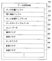
- the data storage area 304 stores touch coordinate map data 334, touch key table data 336, GUI data 338, and the like, and an incoming call flag 340, an incoming flag 342, a touch flag 344, a new arrival flag 346, and an unread flag. 348 and the like are provided.
- the touch position buffer 330 is a buffer for temporarily storing an input result such as a touch detected by the touch panel 38, and temporarily stores, for example, coordinate data of a touch point and a release point.
- the execution function buffer 332 is a buffer in which stored data changes according to processing for managing the function to be executed.
- function IDs are assigned to all functions executed by the mobile terminal 10, and the function IDs of functions currently executed by the CPU 20 are stored in the execution function buffer 332.
- the touch coordinate map data 334 is data for associating coordinates such as a touch point specified by the touch panel control circuit 36 with display coordinates of the second display 34. That is, the CPU 20 can associate the result of the touch operation performed on the touch panel 38 with the display on the second display 34 based on the touch coordinate map data 334.
- the touch key table data 336 includes data indicating whether or not display of the touch key is necessary corresponding to the function ID, and data indicating the type of touch key displayed when the touch key is required to be displayed. Table data to be recorded.
- the GUI data 338 is GUI image data displayed on the first display 26 and the second display 34, and includes, for example, image data for displaying touch keys.
- the incoming call flag 340 is a flag for determining whether or not a call signal is received.
- the incoming call flag 340 is composed of a 1-bit register. When the incoming call flag 340 is turned on (established), a data value “1” is set in the register. On the other hand, when the incoming call flag 340 is turned off (not established), a data value “0” is set in the register.
- the incoming flag 342 is a flag for determining whether or not a new mail is being received.
- the touch flag 344 is a flag for determining whether or not the touch panel 38 is touched (touched).
- the new arrival flag 346 is a flag for determining whether or not a slide operation has been performed after receiving new mail.
- the unread flag 348 is a flag for determining whether or not the text of a new mail has been displayed.
- the incoming flag 342, touch flag 344, new arrival flag 346, and unread flag 348 have the same configuration as the incoming call flag 340, and thus detailed description thereof is omitted.
- the data storage area 304 stores address book data composed of telephone numbers set in other mobile terminals 10, user profile data, and the like. Counters and flags necessary for the operation of the mobile terminal 10 are also provided.
- RTOS Real-time Operating System
- the CPU 20 receives the incoming call process shown in FIG. 12, the incoming call process shown in FIG. 13, and the slide control shown in FIG.
- a plurality of tasks including an incoming call process shown in FIG. 15, an incoming call process shown in FIG. 16, a standby process shown in FIGS. 17 and 18, a touch key control process shown in FIG. 19, and the like are executed in parallel. To do.
- FIG. 12 is a flowchart of incoming call processing.
- the CPU 20 determines whether or not a call signal has been received in step S1. That is, it is determined whether the call signal from the other party is captured by the antenna 12 and the incoming call is notified from the wireless communication circuit 14. If “NO” in the step S1, that is, if the call signal is not captured by the antenna 12, the process of the step S1 is repeated until the call signal is received. On the other hand, if “YES” in the step S1, that is, if the calling signal is caught by the antenna 12, the incoming flag 340 is turned on in a step S3. Subsequently, in step S5, incoming call state processing is started. In the incoming call state process, for example, the LED 46 is turned on. Further, in the incoming call state process, the mobile terminal 10 is vibrated by rotation of a motor (not shown), or an incoming call sound is output from a speaker (not shown).
- step S7 it is determined whether or not the calling signal is interrupted. For example, it is determined whether or not the call signal has been interrupted by establishing a call ready state. If “NO” in the step S7, that is, if the antenna 12 receives the calling signal, the process of the step S7 is repeatedly executed. On the other hand, if “YES” in the step S7, that is, if the call signal is not received by the antenna 12, the call flag 340 is turned off in a step S9, and the call receiving state process is ended in a step S11. Then, when the process of step S11 ends, the process returns to step S1. That is, in step S11, the LED 46 is turned off. Further, the rotation of the motor (not shown) is stopped, and the output from the speaker (not shown) is stopped.
- FIG. 13 is a flowchart of incoming call processing.
- the CPU 20 determines whether or not a new mail notification is received in step S21. That is, it is determined whether or not the antenna 12 has received a new mail notification from a mail server (not shown). If “NO” in the step S21, that is, if a new mail notification is not received, the process of the step S21 is repeatedly executed. On the other hand, if “YES” in the step S21, that is, if a new mail notification is received, the incoming flag 342 is turned on in a step S23, and a new mail is received from the server in a step S25. That is, in step S25, new mail data is received from the mail server.
- step S27 it is determined whether or not reception has been completed. That is, it is determined whether or not all new mail data has been received from the mail server. If “NO” in the step S27, that is, if reception of new mail is not completed, the process of the step S27 is repeatedly executed. On the other hand, if “YES” in the step S27, that is, if reception of new mail is completed, the incoming flag 342 is turned off in a step S29, and the new arrival flag 346 is turned on in a step S31. Subsequently, in step S33, new mail reception processing is started, and the process returns to step S21. That is, in the new mail reception process executed in step S33, the LED 46 is turned on. In the new mail reception process, a motor (not shown) is rotated or a ringing tone is output from a speaker (not shown) as in the incoming call status process.
- FIG. 14 is a flowchart of the slide control process.
- the CPU 20 determines whether or not the mobile terminal 10 is in a slide state in step S41. That is, it is determined whether or not both the first magnetic sensor 40 and the second magnetic sensor 44 output the maximum value. If “NO” in the step S41, that is, if either the first magnetic sensor 40 or the second magnetic sensor 44 outputs the maximum value, it is determined whether or not the end operation is performed in a step S43. . For example, it is determined whether or not the end call key has been pressed for a long time. If “NO” in the step S43, that is, if the ending operation is not performed, the process returns to the step S41. On the other hand, if “YES” in the step S43, that is, if an end operation is performed, the slide control process is ended.
- step S41 determines whether or not a call is being received in a step S45. That is, it is determined whether the incoming call flag 340 is on. If “YES” in the step S45, that is, if the incoming call flag 340 is turned on, an incoming call process is executed in a step S47, and the process returns to the step S41. Note that a detailed description of the incoming call processing will be described later with reference to the flowchart shown in FIG.
- step S45 determines whether or not an incoming call is received in a step S49. That is, it is determined whether the incoming flag 342 is on. If “YES” in the step S49, that is, if the incoming flag 342 is turned on, an incoming call process is executed in a step S51, and the process returns to the step S41.
- step S49 If “NO” in the step S49, that is, if both the incoming call flag 340 and the incoming flag 342 are not turned on, a standby process is executed in a step S53, and the process returns to the step S41. Note that the detailed description of the waiting process will be described later with reference to the flowcharts shown in FIGS. 17 and 18, and thus detailed description thereof will be omitted.
- CPU20 which performs the process of step S1, S27, S45, S49 functions as a judgment part.
- the CPU 20 that executes the processes of steps S1 and S45 functions as an incoming call determination unit, and the CPU 20 that executes the processes of steps S27 and S49 functions as an incoming call determination unit.
- FIG. 15 is a flowchart of the incoming call process executed in step S47 (see FIG. 14).
- the CPU 20 displays the sender information on the second display 34. For example, as shown in FIG. 6B, the telephone number and the name of the other party are displayed on the second display 34 based on the caller information transmitted from the other party.
- step S73 it is determined whether or not it is in an open state. That is, it is determined whether or not the value of the second magnetic sensor 44 is the maximum value. If “YES” in the step S73, that is, if it is in an open state, the process proceeds to a step S79. On the other hand, if “NO” in the step S73, that is, if it is not in the open state, it is determined whether or not it is in a closed state in a step S75. That is, it is determined whether or not the value of the first magnetic sensor 44 is the maximum value. If “NO” in the step S75, that is, if in a slide state, the process returns to the step S73.
- step S75 that is, if it is in a closed state
- the absence response process is started in a step S77, and the process proceeds to the step S89.
- step S77 an answering machine response message is transmitted to the call partner after establishing a call available state.
- step S79 call processing is started in step S79. That is, a call process is established by executing a call process. Subsequently, in the process of step S81, the display on the second display 34 is switched. For example, as shown in FIG. 6C, the second display 34 displays touch keys such as the HF key Ta, the memo key Tb, and the menu key Tc from the telephone number based on the caller information and the name of the other party. It is switched to the image to represent.
- touch keys such as the HF key Ta, the memo key Tb, and the menu key Tc from the telephone number based on the caller information and the name of the other party. It is switched to the image to represent.
- step S83 it is determined whether or not an input operation is performed. For example, it is determined whether an arbitrary touch key displayed on the second display 34 has been operated. Further, when it is determined whether or not the touch key is touched, the determination is made by turning on / off the touch flag 344. Furthermore, when the operated touch key is specified from the plurality of touch keys, the touch key is specified based on the touch point and the release point stored in the touch position buffer 330.
- step S83 If “NO” in the step S83, that is, if an input operation is not performed, the process proceeds to a step S87.
- step S83 if “YES” in the step S83, that is, if an input operation is performed, the operation result is displayed on the first display 26 in a step S85. That is, the power of the first display 26 is turned on and the result of the input operation is displayed. For example, referring to FIG. 6D, when the menu key Tc is operated, the menu screen is displayed on the first display 26.
- a step S87 it is determined whether or not it is a call end operation. That is, it is determined whether or not an operation for ending the call state has been performed.
- the end call operation may be an operation of closing the mobile terminal 10 or an operation of pressing an end call key. If “NO” in the step S87, that is, if the call-ending operation is not performed, the process returns to the step S83. On the other hand, if “YES” in the step S87, that is, if the call-ending operation is performed, the call process is ended in a step S89. That is, the wireless communication circuit 14 is controlled to transmit a call end signal to the call partner.
- step S91 the display is erased, the incoming call process is terminated, and the process returns to the slide control process. That is, in step S91, the display of the second display 34 is turned off to erase the display. Further, if the power of the first display 26 is on, the power of the first display 26 is also turned off.
- FIG. 16 is a flowchart of the incoming call process executed in step S51 (see FIG. 14).
- the CPU 20 displays header information on the second display 34 in step S111. That is, the header information included in the new mail data is displayed on the second display 34. For example, since the header information includes information indicating the sender of the mail, the name of the sender of the new mail is displayed on the second display 34 as shown in FIG. If reception of new mail has not been completed and header information of new mail cannot be obtained, the process of step S111 is not executed until header information of new mail is obtained.
- step S113 it is determined whether or not it is in an open state. If “YES” in the step S113, that is, if it is in an open state, the process proceeds to a step S119. On the other hand, if “NO” in the step S113, that is, if it is not an open state, it is determined whether or not it is a closed state in a step S115. If “NO” in the step S115, that is, if in a slide state, the process returns to the step S113. On the other hand, if “YES” in the step S115, that is, if it is in a closed state, the unread flag 348 is turned on in a step S117, and the process proceeds to a step S129. That is, in step S117, since the text of the new mail is not displayed, the unread flag 348 is turned on.
- step S119 the text of the new mail is displayed on the first display 26 in step S119.
- the text of the new mail is displayed on the first display 26.
- step S121 the display on the second display 34 is switched.
- the display on the second display 34 is switched from the sender name of the new mail to an image representing the reply key Td.
- step S123 it is determined whether or not an input operation is performed. If “NO” in the step S123, that is, if an input operation is not performed, the process proceeds to a step S127. On the other hand, if “YES” in the step S123, that is, if an input operation is performed, the operation result is displayed on the first display 26 in a step S125. For example, when the reply key Td is operated, a reply mail creation screen is displayed on the first display 26.
- a step S127 it is determined whether or not it is in a closed state. If “NO” in the step S127, that is, if the open state is maintained, the process returns to the step S123. On the other hand, if “YES” in the step S127, that is, if the portable terminal 10 is changed from the open state to the closed state, the new arrival flag 346 is turned off in a step S129, and the display is erased in a step S131. That is, in step S131, the power of the second display 34 is turned off, and if the power of the first display 26 is on, the power of the first display 26 is also turned off. Then, when the process of step S131 ends, the incoming call process ends, and the process returns to the slide control process.
- new mail notification information is displayed on the second display 34.
- FIG. 17 is a flowchart of the waiting process executed in step S53 (see FIG. 14).
- the CPU 20 determines whether or not the new arrival flag 346 is on. That is, it is determined whether or not an operation for displaying the second display 34 has been performed since the mobile terminal 10 received a new mail. If “NO” in the step S151, that is, if the new arrival flag 346 is turned off, the process proceeds to a step S181 (see FIG. 18). On the other hand, if “YES” in the step S151, that is, if the new arrival flag 346 is turned on, the new arrival flag 346 is turned off in a step S153, and new mail notification information is displayed on the second display 34 in a step S155. For example, the second display 34 displays a character string “There is new mail” as new mail notification information.
- step S157 it is determined whether or not it is in an open state. If “NO” in the step S157, that is, if not in the open state, the process proceeds to a step S163. On the other hand, if “YES” in the step S157, that is, if it is in the open state, a mail folder screen is displayed on the first display 26 in a step S159. That is, a GUI that can arbitrarily select all received mails is displayed on the first display 26.
- step S161 it is determined whether or not the operation is a new mail display operation. For example, it is determined whether a new mail is selected from the displayed mails by the operation key and the confirmation key is operated. If “YES” in the step S161, that is, if it is a display operation of a new mail, the process proceeds to a step S169. On the other hand, if “NO” in the step S161, that is, if the display operation of new mail is not performed, it is determined whether or not it is in a closed state in a step S163. If “NO” in the step S161, that is, if not closed, the process returns to the step S157.
- step S163 if “YES” in the step S163, that is, if it is closed, the unread flag 348 is turned on in a step S165, and the display is erased in a step S167. That is, the power sources of the first display 26 and the second display 34 are turned off. Then, when the process of step S167 ends, the standby process ends, and the process returns to the slide control process.
- step S169 the display on the second display 34 is switched in step S169. That is, the display on the second display 34 is switched to the display of the touch key, as in the process of step S121.
- step S171 the text of the new mail is displayed on the first display 26. That is, the text of the new mail is displayed on the first display 26 as in the process of step S125.
- step S173 the unread flag 348 is turned off. That is, since the text of the new mail is displayed on the first display 26, the unread flag 348 is turned off.
- step S175 it is determined whether or not an input operation is performed. If “NO” in the step S175, the process proceeds to a step S179. On the other hand, if “YES” in the step S175, the operation result is displayed on the first display 26 in a step S177. Subsequently, in step S179, it is determined whether or not it is in a closed state. If “NO” in the step S179, that is, if the open state is maintained, the process returns to the step S175. On the other hand, if “YES” in the step S179, that is, if the portable terminal 10 is brought into a closed state, the process proceeds to a step S169.
- step S181 if the new arrival flag 346 is off in the waiting process, it is determined whether or not the unread flag 348 is on in step S181. That is, it is determined whether the text of the new mail has never been displayed. If “NO” in the step S181, that is, if the unread flag 348 is turned off, the portable terminal information is displayed on the second display 34 in a step S183. For example, as shown in FIG. 8B, the second display 34 displays the radio wave reception state by the antenna 12, the remaining battery capacity of the rechargeable battery, the current date and time, and the like. Subsequently, in step S185, it is determined whether or not it is in a closed state.
- step S185 If “NO” in the step S185, that is, if not in the closed state, the process of the step S185 is repeatedly executed. On the other hand, if “YES” in the step S185, that is, if the closed state is set, the process proceeds to a step S167. In addition, if it will be in an open state, the image which shows that it is a standby state will be displayed on the 1st display 26. FIG.
- step S187 In the waiting process, if the unread flag 348 is ON, unread mail notification information is displayed on the second display 34 in step S187. For example, as shown in FIG. 8C, the second display 34 displays a character string “There is unread mail”. Subsequently, in step S189, it is determined whether or not a touch operation is performed. That is, it is determined whether or not the touch flag 344 is on while the unread mail notification information is displayed.
- step S189 If “NO” in the step S189, that is, if the touch flag 344 is turned off, it is determined whether or not it is in a closed state in a step S191. If “NO” in the step S191, the process returns to the step S189. On the other hand, if “YES” in the step S191, the process proceeds to a step S167. If “YES” in the step S189, that is, if the touch flag 344 is turned on, the mail folder screen is displayed on the first display 26 in a step S193. That is, the GUI is displayed on the first display 26 as in step S159.
- step S195 it is determined whether or not the operation is a new mail display operation. If “YES” in the step S195, that is, if it is a display operation of a new mail, the process proceeds to a step S169. On the other hand, if “NO” in the step S195, that is, if it is not an operation for displaying a new mail, it is determined whether or not it is in a closed state in a step S197. If “NO” in the step S197, that is, if not in the open state, the process returns to the step S195. On the other hand, if “YES” in the step S197, that is, if the new mail is closed without being displayed, the process proceeds to a step S167.
- CPU20 which performs the process of step S71, S111, S155, S183 functions as an information display part.
- the CPU 20 that executes the processes of steps S79, S119, and S159 functions as a first processing unit.
- the CPU 20 that executes the process of step S79 functions as a call processing unit
- the CPU 20 that executes the process of step S119 functions as a mail display unit.
- FIG. 19 is a flowchart of touch key control processing.
- the CPU 20 acquires data stored in the execution function buffer 332 in step S211. That is, the function ID of the function to be executed is read from the execution function buffer 332.
- CPU20 which performs the process of step S211 functions as an acquisition part.
- step S213 it is determined whether or not a touch key needs to be displayed. That is, in the process of step S213, the function ID read in step S211 is searched in the touch key table data 336, and a determination is made based on data indicating whether the touch key needs to be displayed. If “NO” in the step S213, that is, if it is not necessary to display the touch key, the touch key control process is ended. On the other hand, if “YES” in the step S213, that is, if it is necessary to display a touch key, the touch key corresponding to the function ID is displayed on the second display 34 in a step S215. For example, in the case of a music player function, as shown in FIG.
- the first music selection key Tf, the second music selection key Tg, the first volume key Th, and the second volume key Tj are represented based on the touch key table data 336.
- An image (design) is displayed on the second display 34.
- CPU20 which performs the process of step S215 functions as a symbol display part.
- step S217 it is determined whether or not a touch operation is performed. That is, it is determined whether or not the touch flag 344 is on. If “NO” in the step S217, that is, if the touch flag 344 is turned off, it is determined whether or not the end operation is performed in a step S219. That is, it is determined whether or not an operation for ending the function to be executed has been performed. If “NO” in the step S219, that is, if the end operation is not performed, the process returns to the step S217. On the other hand, if “YES” in the step S219, that is, if an end operation is performed, the touch key control process is ended.
- step S217 If “YES” in the step S217, that is, if the touch flag 344 is turned on, an arbitrary process is executed in accordance with the operated touch key in a step S221. For example, if the first volume key Th is operated while the music player function is being executed, a process for reducing the volume of the music to be played is executed.
- CPU20 which performs the process of step S221 functions as a 2nd process part.
- the mobile terminal 10 includes a first case C1 and a second case C2.
- the mobile terminal 10 is a slide type mobile terminal that is slidably connected in a state where the first case C1 is overlaid on the second case C2.
- a first display 26 is provided on the upper surface of the first case C1.
- a second display 34 is provided at a position that is exposed when a slide operation is performed without being exposed in a normal state (closed state).
- the user can confirm predetermined information such as time on the second display 34 by performing a slide operation. And since the thing smaller than the power consumption of the 1st display 26 is employ
- the first display 26 In the normal state, the first display 26 is in a display state in consideration of privacy. That is, since the predetermined information can be confirmed only when the slide operation is performed, the privacy of the user is protected.
- the display state in consideration of privacy may be a state where nothing is displayed on the first display 26, or a state where the backlight of the first display 26 is turned off. Furthermore, only the information designated by the user may be displayed on the first display 26.
- first display 26 and the second display 34 are provided at positions that can be confirmed simultaneously when a slide operation is performed, convenience for the user is improved.
- an LCD monitor is used for the first display 26 and an organic EL panel is used for the second display 34, but other display devices may be used. Further, a touch panel 38 may be provided on the surface of the first display 34. Furthermore, as the LED 46, a color LED capable of emitting a plurality of colors may be used, and the light emission color may be changed between an incoming call and an incoming call.
- the first case C1 and the second case C2 form the slide type mobile terminal with the two cases.
- the slide type mobile terminal includes three or more cases. It may be.
- an intermediate case slides in the left-right direction and a lowermost case slides in the vertical direction with respect to the uppermost case.
- the first display 26 is provided in the uppermost case
- the second display 34 is provided in a position exposed when either the intermediate case or the lowermost case slides.
- the open state, the closed state, and the slide state are detected by the first magnetic sensor 40, the second magnetic sensor 44, and the magnet 42.
- An open state, a closed state, and a slide state may be detected, or an open state, a closed state, and a slide state may be detected by a combination of a mechanical switch, a magnetic sensor, and a magnet.
- the processes shown in FIGS. 14 to 18 may be executed even if the power saving mode by the power saving function is not set.
- the communication method of the mobile terminal 10 is not limited to the CDMA method, but may be a W-CDMA method, a TDMA method, a PHS method, a GSM method, or the like.
- a PDA Personal Digital Assistant
- a portable information terminal such as a notebook PC, or a portable game machine equipped with a slide mechanism may be used.
Landscapes
- Engineering & Computer Science (AREA)
- Signal Processing (AREA)
- Telephone Function (AREA)
- Telephone Set Structure (AREA)
Abstract
携帯端末10は、第1ケースC1および第2ケースC2を含む。また、携帯端末10は、第1ケースC1が第2ケースC2の上に重ねられた状態で、スライド可能に連結されるスライド型携帯端末である。第1ケースC1の上面には、第1ディスプレイ26が設けられる。また、第2ケースC2の上面には、定常時(閉状態)では、露出せずにスライド操作がされたときに露出する位置に、第2ディスプレイ34が設けられる。たとえば、着呼中に使用者によってスライド状態されると、第2ディスプレイ34には、相手の名前が表示される。
Description
この発明は、携帯端末に関し、特にたとえば複数の筐体がスライド可能に連結される、携帯端末に関する。
従来、特にたとえば複数の筐体がスライド可能に連結される、携帯端末が知られており、この種の装置の一例が、非特許文献1に開示されている。この背景技術のスライド型携帯電話は、上側の筐体に、ディスプレイがむき出しとなるように設けられており、待機状態ではディスプレイの電源がオフにされる。そして、使用者が時刻表示および電池の残容量を確認するときや、着呼およびメールの着信があるときに、ディスプレイとディスプレイのバックライトとの電源がオンにされ、所定の情報がディスプレイに表示される。
また、特許文献1には、スライド式携帯端末が開示されている。この携帯端末は、下側の筐体に、大型液晶表示部および小型液晶表示部を有している。また、短縮状態(閉状態)では、大型液晶表示部が他方の筐体に覆われる位置に設けられているため、小型液晶表示部のみが露出するようにされる。
W61SA by SANYO 取扱説明書 22頁 特開2008-61185号公報[H04M 1/02, H04B 1/38]
W61SA by SANYO 取扱説明書 22頁
近年、携帯電話などの携帯端末では、充電池の使用時間を延長させるために、消費電力を低減させる技術が開発されている。ところが、非特許文献1の携帯電話では、時刻を確認するための単純な操作を行っただけで、ディスプレイとバックライトとの電源がオンになるため、サブディスプレイを備える折り畳み型携帯電話に比べて、消費電力が大きくなってしまう。
また、携帯電話の市場では、ディスプレイの大型化が進んでいるが、スライド型携帯電話では、時刻および電池の残容量を確認するときや、着呼およびメールの着信があるときに、第三者にディスプレイを覗き見されてしまうといった、問題もある。
そこで、特許文献1のように、スライド型携帯電話にも小型液晶表示部(サブディスプレイ)を設けることが考えられたが、次のような問題が新たに発生する。まず、この文献のスライド式携帯端末では、短縮状態でも常に段差が生じてしまい、持ち運びの際にその段差が邪魔になる。次に、大型液晶表示部と小型液晶表示部とが、下側の筐体に設けられるため、短縮状態から伸長状態にスライドさせる際に、非特許文献1などのスライド型携帯電話に比べ、スライドの操作性が悪くなる。そして、短縮状態ではメインディスプレイが隠れてしまうため、スライド型携帯端電話の利点である「閉じたままでの使用」が、実質的にできなくなってしまう。
それゆえに、この発明の主たる目的は、新規な、携帯端末を提供することである。
この発明の他の目的は、消費電力を抑えることができる、携帯端末を提供することである。
この発明のその他の目的は、プライバシーを保護することができる、携帯端末を提供することである。
この発明のさらにその他の目的は、使用者が必要とする情報を的確に提供できる携帯端末およびスライド制御プログラムを提供することである。
この発明は、上記の課題を解決するために、以下の構成を採用した。なお、括弧内の参照符号および補足説明等は、この発明の理解を助けるために記述する実施形態との対応関係を示したものであって、この発明を何ら限定するものではない。
第1の発明は、第1筐体、第1筐体に設けられた第1表示部、第1筐体とスライド可能に連結された少なくとも1つの第2筐体、および定常時には露出せず、スライド操作で露出する位置に設けられる第2表示部を備える、携帯端末である。
第1の発明では、第1筐体(C1)および第2筐体(C2)は、たとえば板状に形成される。また、第1筐体にはLCDモニタなどの第1表示部(26)が設けられる。第1筐体と第2筐体とは、たとえばバネ(56)を含むスライド機構(50)によってスライド可能に連結される。そして、有機ELパネルなどが用いられる第2表示部(34)は、定常時(閉状態)では、露出せずにスライド操作がされたときに露出する位置に設けられる。
第1の発明によれば、使用者は、単純な操作としてスライド操作を行うことで、時刻などの所定の情報を第2表示部によって確認できるようになる。そして、第2表示部に、第1表示部の消費電力よりも小さいものを採用することで、携帯端末の消費電力を抑えることができる。
また、定常時には第1表示部がプライバシーを考慮した表示状態とされる。そのため、スライド操作がされたときのみ、所定の情報を表示することで、使用者のプライバシーを保護することができる。さらに、第2表示部に、第1表示部よりも小さいものを採用することで、プライバシー保護の効果はさらに高まる。
第2の発明は、第1の発明に従属し、第1筐体は、第2筐体の上に積層された状態で連結され、第2表示部は、第2筐体に設けられる。
第2の発明では、第1筐体は、たとえばスライド型携帯端末のように、第2筐体の上に積層される。そして、第2表示部は、たとえば第1筐体と第2筐体とに挟まれるように、第2筐体に設けられる。
第2の発明によれば、第1表示部と第2表示部とは、スライド操作がされると、同時に確認できる位置に設けられるため、使用者の利便性が向上する。
第3の発明は、第1の発明または第2の発明に従属し、特定状態であるか否かを判断する判断部、スライド操作を検出する検出部、および特定状態と判断され、かつスライド操作が検出されたとき、第2表示部に情報を表示させる情報表示部をさらに備える。
第3の発明では、判断部(20,S1,S27,S45,S49)は、携帯端末が使用される状況において、使用頻度が高い状態を、特定状態(着呼状態、着信状態、待機状態)として判断する。検出部(20,40,42,S41)は、たとえば磁気センサが出力する値からスライド操作を検出する。そして、情報表示部(20,S71,S111,S155,S183)は、特定状態に対応して、使用者に通知すべき情報を第2表示部に表示させる。
第3の発明によれば、携帯端末が使用される状況に応じて、使用者が必要とする情報を的確に提供できるようになる。
第4の発明は、第3の発明に従属し、第1筐体と第2筐体とが開状態であるかを検出する開状態検出部、および情報表示部によって情報が表示され、かつ開状態が検出されたとき、所定の処理を実行する第1処理部をさらに備える。
第4の発明では、開状態検出部(20,42,44)は、たとえば磁気センサおよび磁石を利用して、開状態を検出する。第1処理部(20,S79,S119,S159)は、特定状態において、実行される可能性が高い処理を、所定の処理として実行する。
第4の発明によれば、使用者は、第2表示部に表示される情報を確認した後に、スライド操作を継続することで、所定の処理を実行させることができる。
第5の発明は、第4の発明に従属し、特定状態は、着呼状態を含み、判断部は、着呼状態であるかを判断する着呼判断部を含み、第1処理部は、着呼状態であると判断されたとき、通話処理を開始する通話処理部を含む。
第5の発明では、着呼判断部(20,S1,S45)は、特定状態に含まれる着呼状態であるかを判断する。通話処理部(20,S79)は、開状態にされると、通話相手との通話可能状態を確立する。
第5の発明によれば、使用者は、通話相手の情報を確認した後に、通話相手との通話を始めることができる。
第6の発明は、第4の発明に従属し、特定状態は、メールの着信状態を含み、判断部は、着信状態であるかを判断する着信判断部をさらに含み、第1処理部は、着信状態であると判断されたとき、メールの内容を第1表示部に表示させるメール表示部を含む。
第6の発明では、着信判断部(20,S27,S49)は、特定状態に含まれる着信状態であるかを判断する。メール表示部(20,S119)は、開状態にされると、第1表示部にメールの内容(本文)を表示させる。
第6の発明によれば、使用者は、メールの送信者などを確認した後に、メールの本文などを表示させることができる。
第7の発明は、第1の発明に従属し、第2表示部に設けられたタッチ反応領域において、タッチ反応領域内のタッチ操作を検出するタッチ操作検出部、実行される処理の情報を取得する取得部、取得部によって取得された処理の情報に基づいて、第2表示部に図柄を表示させる図柄表示部、および図柄の表示範囲にタッチ操作が含まれるとき、所定の処理を実行する第2処理部をさらに備える。
第7の発明では、タッチ操作検出部(20,38)は、たとえば第2表示部の表面に設けられるタッチパネル(38)を含む。また、タッチ操作検出部は、第2表示部の表示領域と対応するタッチ反応領域において、タッチ操作を検出する。取得部(20,S211)は、たとえば実行される処理(音楽プレイヤ機能)の機能IDを取得する。図柄表示部(20,S215)は、たとえば取得された機能IDに基づいて、タッチキーを表す図柄を第2表示部に表示させる。第2処理部(20,S221)は、図柄の表示範囲に含まれるタッチ操作、つまりタッチキーの操作に応じて、第1処理部とは異なる所定の処理を実行する。
第7の発明によれば、携帯端末で実行される様々な機能に対応するタッチキーを、第2表示部に表示させることができる。これにより、携帯端末の開発者は、操作キーの配置が限られる携帯端末において、第2表示部が設けられる位置を有効に活用することができる。また、実行する機能に応じて、タッチキーが表示されるようになるため、使用者は、実行する機能に対する、入力操作が容易になる。
第8の発明は、請求項1の携帯端末(10)のプロセサ(20)を、特定状態(着呼状態、着信状態、待機状態)であるか否かを判断する判断部(S1,S25,S43,S47)、スライド操作を検出する検出部(S41)、および特定状態と判断され、かつスライド操作が検出されたとき、第2表示部に情報を表示させる情報表示部(S71,S111,S153)として機能させる、スライド制御プログラムである。
第8の発明でも、第3の発明と同様に、携帯端末が利用される状況に応じて、使用者が必要とする情報を的確に提供できるようになる。
この発明によれば、単純な操作がされたときに、消費電力が低い表示部に所定の情報を表示させることで、携帯端末の消費電力を抑えることができる。
また、定常時には一方の表示部がプライバシーを考慮した表示状態とされ、単純な操作がされたときに露出する他方の表示部に所定の情報を表示させることで、使用者のプライバシーを保護することができる。
さらに、携帯端末が使用される状況に応じて、使用者が必要とする情報を的確に提供できるようになる。
この発明の上述の目的、その他の目的、特徴および利点は、図面を参照して行う以下の実施例の詳細な説明から一層明らかとなろう。
図1を参照して、携帯端末10は、CPU(プロセサまたはコンピュータと呼ばれることもある。)20および入力装置であるキー入力装置22を含む。CPU20は、CDMA方式に対応する無線通信回路14を制御して発呼信号を出力する。出力された発呼信号は、アンテナ12から送出され、基地局を含む移動通信網に送信される。通話相手が応答操作を行うと、通話可能状態が確立される。
通話可能状態に移行した後にキー入力装置22によって通話終了操作が行われると、CPU20は、無線通信回路14を制御して、通話相手に通話終了信号を送信する。そして、通話終了信号の送信後、CPU20は、通話処理を終了する。また、先に通話相手から通話終了信号を受信した場合も、CPU20は、通話処理を終了する。さらに、通話相手によらず、移動通信網から通話終了信号を受信した場合も、CPU20は通話処理を終了する。
携帯端末10が起動している状態で通話相手からの発呼信号がアンテナ12によって捉えられると、無線通信回路14は、着呼をCPU20に通知する。CPU20は、LED46を点灯させると共に、図示しないスピーカから着呼音を出力させる。なお、CPU20は、図示しないモータを駆動(回転)させることで携帯端末10を振動させ、着呼を使用者に通知するようにしてもよい。
そして、CPU20は、第1表示ドライバ24または第2表示ドライバ32を制御することで、発呼信号と共に通話相手から送信される発信元情報を第1ディスプレイ26または第2表示ディスプレイ34に表示させる。
通話可能状態では、次のような処理が実行される。通話相手から送られてきた変調音声信号(高周波信号)は、アンテナ12によって受信される。受信された変調音声信号は、無線通信回路14によって復調処理および復号処理が施される。そして、得られた受話音声信号は、スピーカ18から出力される。一方、マイク16によって取り込まれた送話音声信号は、無線通信回路14によって符号化処理および変調処理が施される。そして、生成された変調音声信号は、上述と同様、アンテナ12を利用して通話相手に送信される。
タッチパネル38は、第2ディスプレイ34の画面内で、任意の位置を指示するためのポインティングデバイスである。タッチパネル38は、その上面を指で、押したり、撫でたり、触られたりすることにより操作されると、その操作を検出する。そして、タッチパネル38に指が触れると、タッチパネル制御回路36は、その指の位置を特定し、操作された位置の座標データをCPU20に出力する。つまり、使用者は、タッチパネル38の上面を指で、押したり、撫でたり、触れたりすることによって、操作の方向や図形などを携帯端末10に入力することができる。
また、タッチパネル38は、指がタッチパネル38の表面に接近して生じた電極間の静電容量の変化を検出する静電容量方式と呼ばれる方式で、1本または複数本の指がタッチパネル38に触れたことを検出する。具体的には、このタッチパネル38は、電極パターンが形成された透明フィルムに、指が接近することで生じる電極間の静電容量の変化を検出する、投影型の静電容量方式が採用されている。なお、検出方式には、表面型の静電容量方式が採用されてもよいし、抵抗膜方式、超音波方式、赤外線方式および電磁誘導方式などであってもよい。
ここで、使用者がタッチパネル38の上面を指で触れる操作を「タッチ」と言うことにする。一方、タッチパネル38から指を離す操作を「リリース」と言うことにする。そして、タッチによって示された座標を「タッチ点」、リリースによって示された座標を「リリース点」と言うことにする。さらに、使用者がタッチパネル38の上面をタッチして、続けてリリースする操作を「タッチアンドリリース」と言うことにする。そして、タッチパネル38に対して行う、タッチ、リリースおよびタッチアンドリリースなどの操作を、総じて「タッチ操作」と言うことにする。
なお、タッチ点は、タッチパネル38に触れている指の面積の重心座標となる。また、タッチ操作を行うために、専用のタッチペンなどを備えるようにしてもよい。さらに、第2ディスプレイ34の表示座標と、タッチパネル38のタッチ位置座標との原点は左上端とする。つまり、横座標は左上端から右上端に向けて大きくなり、縦座標は左上端から左下端に向けて大きくなる。そして、CPU20およびタッチパネル38は、タッチ操作検出部として機能する。
また、携帯端末10は、メール機能を備えており、図示しないメールサーバとのデータ通信を行い、メールの送受信を行うことができる。なお、データ通信中における、アンテナ12および無線通信回路14は通信部として機能し、メールサーバなどは有線または無線でネットワークと接続されている。
さらに、携帯端末10は、RAM30に記憶されている音楽データを管理および再生するための音楽プレイヤ機能を備える。使用者は、音楽データの再生操作を行うと、携帯端末10を利用して音楽を楽しむことができる。
図2(A)は携帯端末10の閉状態の外観を示す図解図であり、図2(B)は携帯端末10の開状態の外観を示す図解図である。図2(A)、図2(B)を参照して、携帯端末10は、各々が板状に形成された第1ケースC1(第1筐体)および第2ケースC2(第2筐体)を有する。また、第1ケースC1と第2ケースC2との厚みは略同じであり、第1ケースC1は第2ケースC2の上に重ねられた状態(積層された状態)で、スライド機構50(図3参照)によって連結される。そして、第1ケースC1は、第2ケースC2の長さ方向にスライドできる。なお、アンテナ12は、第1ケースC1または第2ケースC2に内蔵されており、図2(A)、図2(B)では、図示されない。
また、図示しないマイク16は、第2ケースC2に内蔵され、内蔵されたマイク16に通じる開口OP2は第2ケースC2の長さ方向一方の上面に設けられる。同じく、図示しないスピーカ18は、第1ケースC1に内蔵され、内蔵されたスピーカ18に通じる開口OP1は、第1ケースC1の長さ方向一方の上面に設けられる。
キー入力装置22は、複数のキーを含む第1キー群22aと第2キー群22bとを含む。第1キー群22aは、方向キー、通話キー、終話キー、メニューキーおよび確定キーから構成されており、第1ケースC1の上面に設けられる。また、第2キー群22bは、0~9の数字キーなどから構成されており、第2ケースC2の上面に設けられる。また、第1ディスプレイ26は、モニタ画面が第1ケースC1の上面に露出するように取り付けられる。第2ディスプレイ34は、モニタ画面が第2ケースC2の上面に露出するように取り付けられる。さらに、第2ディスプレイ34の表面には、タッチパネル38が設けられる。そして、LED46は、発光部が第1ケースC1の長さ方向一方の主面に露出するように設けられる。
たとえば、使用者は、第1ディスプレイ26を確認しながら、0~9の数字キーを操作して電話番号を入力し、通話キーによって発呼操作を行うことができる。そして、使用者は、終話キーによって通話終了操作を行う。また、使用者は、メニューキーを操作することでメニュー画面を表示し、方向キーによって任意のメニューを選択することができる。そして、使用者は、確定キーを操作することで、選択されたメニューを確定することができる。
なお、使用者は、終話キーを長押しすることで携帯端末10の電源をオン/オフする。また、本実施例では、第2ディスプレイ34の面積は、第1ディスプレイ26に比べて小さい。そのため、第2ディスプレイ34の消費電力は、第1ディスプレイ26の消費電力に比べて小さくなる。
第1磁気センサ40は第2ケースC2の長さ方向一方に内蔵される。磁石42は、図2(A)に示す閉状態で、第1磁気センサ40と最も近い状態となるように、第1ケースC1の長さ方向他方に内蔵される。そして、第2磁気センサ44は、図2(B)に示す開状態で、磁石42と最も近い状態となるように、第2ケースC2の中央付近に内蔵される。
そして、携帯端末10の閉状態を検出する第1磁気センサ40は、図2(A)に示す状態では最大値を出力する。一方、携帯端末10の開状態を検出する第2磁気センサ44は、図2(B)に示す状態では最大値を出力する。つまり、CPU20は、第1磁気センサ40が最大値を出力するときに閉状態を検出し、第2磁気センサ44が最大値を出力するときに開状態を検出する。
ここで、本実施例では、第1磁気センサ40および第2磁気センサ44のそれぞれが、最大値を出力していない状態を「スライド状態」と言うことにする。たとえば、使用者が、閉状態で第1ケースC1をスライドさせると、携帯端末10は閉状態からスライド状態に遷移する。そして、使用者が、第1ケースC1をさらにスライドさせると、携帯端末10は、スライド状態から開状態に遷移する。
このように、第2ディスプレイ34は、定常時(閉状態)には露出せず、スライド操作がされると露出する位置に設けられている。
なお、第1ケースC1と第2ケースC2とは、スライドによる影響を受けないフレキシブルハーネスによって電気的に接続される。また、他の外観図では、第1キー群22a、第2キー群22b、第1ディスプレイ26、第2ディスプレイ34、タッチパネル38、第1磁気センサ40、LED46、開口OP1および開口OP2の参照符号を、簡単のため省略することがある。さらに、本実施例では、CPU20、第1磁気センサ40および磁石42は閉状態検出部として機能し、CPU20、磁石42および第2磁気センサ44は開状態検出部として機能する。
図3はスライド機構50の表面の外観を示す図解図であり、図4はスライド機構の裏面の外観を示す図解図である。なお、図3および図4では、スライド機構50と、第1ケースC1および第2ケースC2との関係を明確にするために、第1ケースC1と第2ケースC2との外観も図示する。
図3および図4を参照して、スライド機構50は、第1プレート52、第2プレート54および保持部として機能するバネ56から構成されている。また、スライド機構50は、第1ケースC1と第2ケースC2との間に有り、第1プレート52は第2ケースC2の上面に連結され、第2プレート54は第1ケースC1の下面に連結される。そして、第1プレート52は、第2プレート54に対してスライドするように組み合わせられる。すなわち、第1プレート52が第2プレート54に対してスライドすることで、第1ケースC1が第2ケースC2に対してスライドする。
なお、本実施例では、第1プレート52および第2プレート54は、それぞれ第1ケースC1および第2ケースC2に対して、ネジにより軸止めされることで連結されてもよいし、凹部と凸部との嵌合などによって連結されてもよい。
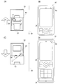
図5(A)-図5(D)を用いて、携帯端末10の開状態または閉状態を保持する、バネ56について詳細に説明する。
図5(A)を参照して、携帯端末10が閉状態(図5(B))である場合に、第1プレート52は、第2プレート54の上側に位置しており、バネ56の力F1によって、第1プレート52と第2プレート54との状態が維持される。つまり、閉状態の携帯端末10に対して、矢印D1の方向に外力が加えられたとしても、外力がバネ56の力F1を超えない限り、閉状態が保持される。さらに、第1ケースC1に対して、第2ケースC2が矢印D1の方向にスライドしても、スライド量が一定量を超えない限りは、バネ56による力F1によって、スライド状態は閉状態に戻される。
また、スライド量が一定量を超えると、バネ56の力F1の方向が反転し、力F2が働くようになる。これにより、第2ケースC2は、矢印D2の方向にスライドが補助されて、図5(D)に示す開状態になる。
図5(C)を参照して、携帯端末10が開状態(図5(D))である場合に、第1プレート52は、第2プレートの下側に位置しており、バネ56の力F2によって、第1プレート52と第2プレート54と状態が維持される。つまり、閉状態と同様に、バネ56によって携帯端末10の開状態が保持される。
このように、スライド機構50が備えるバネ56によって、携帯端末10の開状態または閉状態が保持されると共に、第1ケースC1または第2ケースC2に対するスライド操作が補助される。
なお、本実施例における「スライド量の一定量」とは、第1ケースC1が閉状態から開状態にスライドしたときの移動距離に対して、半分の距離となる。たとえば、使用者が閉状態の携帯端末10に対して、第2ディスプレイ34のみを露出させるスライド操作を行ってから、そのスライド操作を中断すると、携帯端末10はスライド状態から閉状態に戻される。
また、本実施例におけるスライド機構では、1つのバネでスライドを補助しているが、2本以上のバネを利用してスライドを補助してもよい。また、本実施例では、バネ56にコイルバネを用いたが、板バネなどの他の種類のバネが用いられてもよい。
ここで、本実施例では、携帯端末10は省電力機能を有しており、使用者は、携帯端末10に対して省電力モードを設定することができる。この省電力モードは、電話の着呼状態、メールの着信状態および待機状態などの使用頻度が高い状態(特定状態)では、第1ディスプレイ26の電源をオフにする。さらに、省電力モードの携帯端末10は、電話の着呼とメールの着信との通知情報や、携帯端末情報(時刻や残電池容量)などの所定の情報を、スライド操作がされたときのみ、第2ディスプレイ34に表示させる。
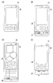
まず、図6(A)-図6(F)を用いて、着呼中(着呼状態)のスライド操作について説明する。着呼中の携帯端末10では、図6(A)に示すようにLED46が発光(点灯)する。そして、使用者が着呼中の携帯端末10に対してスライド操作を行うと、第2ディスプレイ34には発信元情報が表示される。たとえば、図6(B)を参照して、第2ディスプレイ34には相手の電話番号と共に、電話番号に対応する相手の名前が表示される。なお、相手の名前は、携帯端末10のRAM30に記録されるアドレス帳データに基づいて表示される。
また、使用者がスライド操作を継続して行い、開状態にすると、通話可能状態が確立され、LED46の発光が停止される。さらに、通話状態では、第2ディスプレイ34には、複数の機能キーが表示される。使用者は、表示された複数の機能キーに対して、タッチ操作を行うことで、任意の機能キーを操作することができる。たとえば、図6(C)を参照して、第2ディスプレイ34には、HF(Hands Free)キーTa、メモキーTbおよびメニューキーTcが表示される。HFキーTaが操作されると、ハンズフリー通話に切り替わる。また、メモキーTbが操作されると、通話音声がRAM30に記録(録音)される。そして、メニューキーTcが操作されると、図6(D)に示すように、第1ディスプレイ26にメニュー画面が表示される。
そして、図6(E)を参照して、通話状態でスライド操作によって携帯端末10が閉状態にされると、終話キーが操作されたときと同じように、携帯端末10は、通話終了信号を送信して、通話処理を終了する。つまり、携帯端末10が待機状態となる。また、携帯端末10が閉状態にされると、第1ディスプレイ26および第2ディスプレイ34の表示は消去される。
このように、使用者は、通話相手の情報を確認した後に、通話相手との通話を始めることができる。
なお、通話可能状態が確立された場合に、第2ディスプレイ34には、図6(F)に示すように、通話時間が表示されてもよい。また、図6(B)に示すスライド状態において、スライド操作が中断されて携帯端末10が閉状態に戻ると、不在応答処理が実行される。この不在応答処理では、通話可能状態を確立した後に、留守番応答メッセージを通話相手に送ってもよいし、通話可能状態を確立することなく通話終了信号を送信してもよい。また、誤ってスライド操作を中断してしまうことを考慮し、閉状態に戻っても図6(A)のように着呼中(着呼状態)に戻り、所定時間その状態を維持するようにしてもよい。この場合、所定時間後に、前述した不在応答処理を実行してもよいし、通話可能状態を確立することなく通話終了信号を送信してもよい。
図7(A)-図7(D)を用いて、メールの着信中(着信状態)のスライド操作について説明する。図7(A)を参照して、携帯端末10は、着呼中と同様に、着信中にLED46を発光(点灯)させることで、メールの着信を通知する。そして、使用者がメールの着信中にスライド操作を行うと、第2ディスプレイ34に、メールのヘッダ情報が表示される。たとえば、図7(B)を参照して、第2ディスプレイ34には、発信者の名前が表示される。また、メールの件名などメールのヘッダ情報のみを表示してもよいし、発信者の名前と合わせて表示してもよい。
図7(B)に示すスライド状態で、スライド操作が継続されて、携帯端末10が開状態にされると、図7(C)に示すように、新たに受信したメール(新着メール)の本文が第1ディスプレイ26に表示される。さらに、第2ディスプレイ34には返信キーTdが表示される。たとえば、使用者は、この返信キーTdを操作することで、第1ディスプレイ26に返信メール作成画面を表示させることができる。
そして、図7(C)に示すスライド状態で、スライド操作がされて、携帯端末10が閉状態にされると、第1ディスプレイ26および第2ディスプレイ34の表示は消去される。
このように、使用者は、メールの送信者などを確認した後に、メールの本文を表示させることができる。
図8(A)-図8(D)を用いて、待機中(待機状態)におけるスライド操作について詳細に説明する。図8(A)に示す状態で、スライド操作によって、携帯端末10がスライド状態になると、携帯端末情報が、第2ディスプレイ34に表示される。たとえば、図8(B)を参照して、第2ディスプレイ34には、携帯端末情報としてアンテナ12による電波受信状態、充電池の残電池容量および現在日時などが表示される。
また、図8(B)に示す状態で、さらにスライド操作が行われ、携帯端末10が開状態となると、図8(C)に示すように、第1ディスプレイ26には待機状態を表す待機画像が表示される。
さらに、図8(D)を参照して、新着メールの本文一度も確認されていない状態であれば、未読メール通知情報が第2ディスプレイ34に表示される。たとえば、未読メール通知情報は、「未読メールあり」などの文字列や、専用の画像アイコンで、第2ディスプレイに表示される。また、未読メール通知情報が表示された第2ディスプレイ34は、ショートカットキーTeとして機能する。そして、使用者は、このショートカットキー34Teを操作することで、メールフォルダ画面を第1ディスプレイ26に表示させることができる。
なお、新着メールが1度も確認されていなければ、新着メール通知情報が第2ディスプレイ34に表示される。たとえば、「新着メールあり」などの文字列や、専用の画像アイコンが、新着メール通知情報として第2ディスプレイ34に表示される。
このように、本実施例の携帯端末10では、使用される状況に応じて、使用者が必要とする情報を的確に提供できるようになる。また、使用者は、第2ディスプレイ34に表示される情報を確認した後に、スライド操作を継続することで容易に、所定の処理を実行させることができる。なお、ここでの「所定の処理」とは、特定状態で実行される可能性が高い処理(通話処理や、本文表示処理)のことである。
ここで、図9を用いて、任意の機能が実行された場合の第2ディスプレイ34の表示について詳細に説明する。図9を参照して、たとえば音楽プレイヤ機能が実行される場合に、第2ディスプレイ34には、第1選曲キーTf、第2選曲キーTg、第1音量キーThおよび第2音量キーTjが表示される。そして、第1選曲キーTfが操作されると、前回再生されていた曲が選択され、第2選曲キーTgが操作されると、次に再生される曲が選択される。また、第1音量キーThが操作されると、図示しないスピーカなどから出力される音量を小さくし、第2音量キーTgが操作されると、音量を大きくする。
なお、ネットワーク上のサーバのデータを閲覧するブラウザ機能が実行される場合には、表示される画面を上下にスクロールさせる上下スクロールキーや、左右にスクロールさせる左右スクロールキーが第2ディスプレイ34に表示される。また、TVチューナを備える携帯端末10でTV視聴機能が実行される場合には、チャンネルの選局キーおよび音量キーが第2ディスプレイ34に表示される。さらに、カメラモジュールを備える携帯端末10で、カメラ機能が実行される場合には、ズーム調節キーおよび明るさ調節キーなどが第2ディスプレイ34に表示される。
このように、携帯端末10で実行される様々な機能に対応するタッチキーを、第2ディスプレイ34に表示させることができる。これにより、携帯端末10の開発者は、操作キーの配置が限られる携帯端末10において、第2ディスプレイ34が設けられる位置を有効に活用することができる。また、実行する機能に応じて、タッチキーが表示されるようになるため、使用者は、実行する機能に対する、入力操作が容易になる。
図10は、RAM30のメモリマップを示す図解図である。図10を参照して、RAM30のメモリマップには、プログラム記憶領域302およびデータ記憶領域304が含まれる。プログラムおよびデータの一部は、フラッシュメモリ28から一度に全部または必要に応じて部分的にかつ順次的に読みだされ、RAM30に記憶されてからCPU20などで処理される。
プログラム記憶領域302は、携帯端末10を動作させるためのプログラムを記憶する。携帯端末10を動作させるためのプログラムは、着呼プログラム310、着信プログラム312、スライド制御プログラム314およびタッチキー制御プログラム316などによって構成される。
着呼プログラム310は、発呼信号の受信を連続的に確認するためのプログラムであり、LED46を発光させる着呼状態処理などを実行させたりもする。着信プログラム312は、メールサーバからの新着メール通知を連続的に確認するためのプログラムである。スライド制御プログラム314は、スライド操作がされたときの第2ディスプレイ34の表示を制御するためのプログラムであり、さらに着呼中プログラム314a、着信中プログラム314bおよび待機中プログラム314cを含む。
着呼中プログラム314aは、着呼中にスライド操作がされたときに、第2ディスプレイ34の表示を制御するためのプログラムである。また、着信中プログラム314bは、メールの着信中にスライド操作がされたときに、第2ディスプレイ34の表示を制御するためのプログラムである。そして、待機中プログラム314cは、待機中にスライド操作がされたときに、第2ディスプレイ34の表示を制御するためのプログラムである。
タッチキー制御プログラム316は、任意の機能が実行される際に、第2ディスプレイ34に表示されるタッチキー(第1選曲キーTfや、第1音量キーThなど)を制御するためのプルログラムである。
なお、図示は省略するが、携帯端末10を動作させるためのプログラムは、受信メール、送信メールを管理するためのプルログラムや、ネットワークのサーバとのデータ通信を行うためのプログラムおよび音楽データを管理および再生するためのプログラムなどを含む。
図11を参照して、データ記憶領域304には、タッチ位置バッファ330および実行機能バッファ332などが設けられる。また、データ記憶領域304には、タッチ座標マップデータ334、タッチキーテーブルデータ336およびGUIデータ338などが記憶されると共に、着呼フラグ340、着信フラグ342、タッチフラグ344、新着フラグ346および未読フラグ348などが設けられる。
タッチ位置バッファ330は、タッチパネル38によって検出されたタッチなどの入力結果を一時記憶するためのバッファであり、たとえばタッチ点およびリリース点の座標データを一時的に記憶する。実行機能バッファ332は、実行される機能を管理する処理に応じて、格納されるデータが変化するバッファである。ここで、携帯端末10によって実行される全て機能には、機能IDが割り振られており、この実行機能バッファ332には、CPU20によって現在実行されている機能の機能IDが格納される。
タッチ座標マップデータ334は、タッチパネル制御回路36によって特定されるタッチ点などの座標を、第2ディスプレイ34の表示座標と対応付けるためのデータである。つまり、CPU20は、タッチ座標マップデータ334に基づいて、タッチパネル38に対して行われたタッチ操作の結果を第2ディスプレイ34の表示に対応付けることができる。
タッチキーテーブルデータ336は、機能IDに対応して、タッチキーの表示が必要か否かを示すデータと、タッチキーの表示が必要な場合に、表示されるタッチキーの種類を示すデータとが記録されるテーブルデータである。GUIデータ338は、第1ディスプレイ26および第2ディスプレイ34に表示されるGUIの画像データであり、たとえばタッチキーを表示するための画像データなども含まれる。
着呼フラグ340は、発呼信号を受信しているか否かを判断するためのフラグである。たとえば、着呼フラグ340は、1ビットのレジスタで構成される。着呼フラグ340がオン(成立)されると、レジスタにはデータ値「1」が設定される。一方、着呼フラグ340がオフ(不成立)されると、レジスタにはデータ値「0」が設定される。
着信フラグ342は、新着メールを受信している状態か否かを判断するためのフラグである。また、タッチフラグ344は、タッチパネル38にタッチしているか(触れているか)否かを判断するためのフラグである。新着フラグ346は、新着メール受信後にスライド操作がされたか否かを判断するためにフラグである。未読フラグ348は、新着メールの本文が表示されたか否かを判断するためのフラグである。なお、着信フラグ342、タッチフラグ344、新着フラグ346および未読フラグ348の構成は、着呼フラグ340と同じであるため、詳細な説明は省略する。
なお、図示は省略するが、データ記憶領域304には、他の携帯端末10に設定されている電話番号などから構成されるアドレス帳データや、使用者のプロフィールのデータなどが記憶されると共に、携帯端末10の動作に必要なカウンタや、フラグも設けられる。
CPU20は、「Linux(登録商標)」および「REX」などのRTOS(Real-time Operating System)の制御下で、図12に示す着呼処理、図13に示す着信処理、図14に示すスライド制御処理、図15に示す着呼中処理、図16に示す着信中処理、図17と図18とに示す待機中処理および図19に示すタッチキー制御処理などを含む複数のタスクを並列的に実行する。
図12は、着呼処理のフロー図である。たとえば、携帯端末10の電源がオンになると、CPU20は、ステップS1で、発呼信号を受信したか否かを判断する。つまり、通話相手からの発呼信号がアンテナ12によって捉えられ、無線通信回路14から着呼が通知されたか否かを判断する。ステップS1で“NO”であれば、つまり発呼信号がアンテナ12によって捉えられなければ、発呼信号を受信するまでステップS1の処理を繰り返す。一方、ステップS1で“YES”であれば、つまり発呼信号がアンテナ12によって捉えられれば、ステップS3で着呼フラグ340をオンにする。続いて、ステップS5では、着呼状態処理を開始する。着呼状態処理では、たとえばLED46を点灯させる。さらに、着呼状態処理では、図示しないモータの回転によって携帯端末10を振動させたり、図示しないスピーカから着呼音を出力させたりする。
続いて、ステップS7では、発呼信号が途絶したか否かを判断する。たとえば、通話可能状態が確立されることで、発呼信号が途絶したか否かを判断する。ステップS7で“NO”であれば、つまりアンテナ12が発呼信号を受信していれば、ステップS7の処理を繰り返し実行する。一方、ステップS7で“YES”であれば、つまりアンテナ12によって発呼信号が受信されなければ、ステップS9で着呼フラグ340をオフにし、ステップS11で着呼状態処理を終了する。そして、ステップS11の処理が終了すると、ステップS1に戻る。つまり、ステップS11では、LED46を消灯する。さらに、図示しないモータの回転を停止させ、図示しないスピーカからの出力を停止させる。
図13は、着信処理のフロー図である。たとえば、携帯端末10の電源がオンになると、CPU20は、ステップS21で、新着メール通知を受信したか否かを判断する。つまり、図示しないメールサーバからの新着メール通知を、アンテナ12が受信したか否かを判断する。ステップS21で“NO”であれば、つまり新着メール通知を受信してなければ、ステップS21の処理を繰り返し実行する。一方、ステップS21で“YES”であれば、つまり新着メール通知を受信すれば、ステップS23で着信フラグ342をオンにし、ステップS25で、サーバから新着メールを受信する。つまり、ステップS25では、メールサーバから、新着メールのデータを受信する。
ステップS27では、受信を完了したか否かを判断する。つまり、新着メールのデータを、メールサーバから全て受信し終えたか否かを判断する。ステップS27で“NO”でれば、つまり新着メールの受信が完了していなければ、ステップS27の処理を繰り返し実行する。一方、ステップS27で“YES”であれば、つまり新着メールの受信が完了すれば、ステップS29で着信フラグ342をオフにし、ステップS31で新着フラグ346をオンにする。続いて、ステップS33では、新着メール受信処理を開始し、ステップS21に戻る。つまり、ステップS33で実行される新着メール受信処理では、LED46を点灯させる。なお、新着メール受信処理では、着呼状態処理と同様に、図示しないモータを回転させたり、図示しないスピーカから着信音を出力させたりする。
図14は、スライド制御処理のフロー図である。たとえば、携帯端末10の電源がオンになると、CPU20は、ステップS41で、スライド状態になったか否かを判断する。つまり、第1磁気センサ40および第2磁気センサ44が共に、最大値を出力していないか否かを判断する。ステップS41で“NO”であれば、つまり第1磁気センサ40または第2磁気センサ44のいずれか一方が、最大値を出力していれば、ステップS43で終了操作がされた否かを判断する。たとえば、終話キーが長押し操作されたか否かを判断する。ステップS43で“NO”であれば、つまり終了操作がされていなければステップS41に戻る。一方、ステップS43で“YES”であれば、つまり終了操作がされれば、スライド制御処理を終了する。
また、ステップS41で“YES”であれば、つまり、第1磁気センサ40および第2磁気センサ44が共に、最大値を出力していなければ、ステップS45で着呼中か否かを判断する。つまり、着呼フラグ340がオンであるか否かを判断する。ステップS45で“YES”であれば、つまり着呼フラグ340がオンであれば、ステップS47で着呼中処理を実行し、ステップS41に戻る。なお、着呼中処理の詳細な説明は、図15に示すフロー図を用いて後述するため、ここでは詳細な説明を省略する。
一方、ステップS45で“NO”であれば、つまり着呼フラグ340がオフであれば、ステップS49で着信中か否かを判断する。つまり、着信フラグ342がオンであるか否かを判断する。ステップS49で“YES”であれば、つまり着信フラグ342がオンであれば、ステップS51で着信中処理を実行し、ステップS41に戻る。なお、着信中処理の詳細な説明は、図16に示すフロー図を用いて後述するため、ここでの詳細な説明は省略する。
また、ステップS49で“NO”であれば、つまり着呼フラグ340および着信フラグ342が共にオンでなければ、ステップS53で待機中処理を実行し、ステップS41に戻る。なお、待機中処理の詳細な説明は、図17と図18とに示すフロー図を用いて後述するため、ここでの詳細な説明は省略する。
なお、ステップS1、S27,S45,S49の処理を実行するCPU20は、判断部として機能する。また、ステップS1,S45の処理を実行するCPU20は着呼判断部として機能し、ステップS27,S49の処理を実行するCPU20は着信判断部として機能する。
図15は、ステップS47(図14参照)で実行される着呼中処理のフロー図である。CPU20は、ステップS71で、第2ディスプレイ34に発信元情報を表示する。たとえば、図6(B)に示すように、通話相手から送信された発信元情報に基づいて、電話番号や、通話相手の名前が第2ディスプレイ34に表示される。
続いて、ステップS73では、開状態か否かを判断する。つまり、第2磁気センサ44の値が最大値であるか否かを判断する。ステップS73で“YES”であれば、つまり開状態であれば、ステップS79に進む。一方、ステップS73で“NO”であれば、つまり開状態でなければ、ステップS75で閉状態か否かを判断する。つまり、第1磁気センサ44の値が最大値であるか否かを判断する。ステップS75で“NO”であれば、つまりスライド状態であれば、ステップS73に戻る。一方、ステップS75で“YES”であれば、つまり閉状態であれば、ステップS77で不在応答処理を開始して、ステップS89に進む。たとえば、ステップS77では、通話可能状態を確立した後に、留守番応答メッセージを通話相手に送信する。
また、携帯端末10が開状態にされれば、ステップS79で通話処理を開始する。つまり、通話処理を実行することで、通話可能状態を確立する。続いて、ステップS81の処理では、第2ディスプレイ34の表示を切り替える。たとえば、図6(C)に示すように、第2ディスプレイ34の表示は、発信元情報に基づいた電話番号や通話相手の名前から、HFキーTa、メモキーTbおよびメニューキーTcなどのタッチキーを表す画像に切り替えられる。
続いて、ステップS83では、入力操作か否かを判断する。たとえば、第2ディスプレイ34に表示される任意のタッチキーが操作されたか否かを判断する。また、タッチキーに対するタッチの有無を判断する場合には、タッチフラグ344のオン/オフによって判断する。さらに、複数のタッチキーの中から、操作されたタッチキーを特定する場合には、タッチ位置バッファ330に格納されるタッチ点およびリリース点に基づいて特定される。
ステップS83で“NO”であれば、つまり入力操作がされなければ、ステップS87に進む。一方、ステップS83で“YES”であれば、つまり入力操作がされれば、ステップS85で第1ディスプレイ26に操作結果を表示させる。つまり、第1ディスプレイ26の電源をオンにして、入力操作の結果を表示させる。たとえば、図6(D)を参照して、メニューキーTcが操作されれば、メニュー画面を第1ディスプレイ26に表示させる。
続いて、ステップS87では、終話操作か否かを判断する。つまり、通話状態を終了させるための操作がされたか否かを判断する。なお、終話操作としては、携帯端末10を閉状態にする操作であってもよいし、終話キーを押下する操作であってもよい。ステップS87で“NO”であれば、つまり終話操作がされなければ、ステップS83に戻る。一方、ステップS87で“YES”であれば、つまり終話操作がされれば、ステップS89で通話処理を終了する。つまり、無線通信回路14を制御して、通話相手に通話終了信号を送信する。続いて、ステップS91では、表示を消去し、着呼中処理を終了して、スライド制御処理に戻る。つまり、ステップS91では、第2ディスプレイ34の電源をオフにして表示を消去する。さらに、第1ディスプレイ26の電源がオンであれば、第1ディスプレイ26の電源もオフにする。
なお、スライド操作中に着呼状態でなくなった場合には、着呼に対して応答しなかったことを表す「新着呼履歴あり」などの文字列が、第2ディスプレイ34に表示される。
図16は、ステップS51(図14参照)で実行される着信中処理のフロー図である。CPU20は、ステップS111で第2ディスプレイ34にヘッダ情報を表示させる。つまり、新着メールのデータに含まれるヘッダ情報を、第2ディスプレイ34に表示させる。たとえば、ヘッダ情報にはメールの送信者を示す情報が含まれるため、第2ディスプレイ34には、図7(B)に示すように、新着メールの送信者名が表示される。なお、新着メールの受信が完了しておらず、新着メールのヘッダ情報を得られない場合には、ステップS111の処理は、新着メールのヘッダ情報が得られるまで、実行されない。
ステップS113では、開状態か否かを判断する。ステップS113で“YES”であれば、つまり開状態であれば、ステップS119に進む。一方、ステップS113で“NO”であれば、つまり開状態でなければ、ステップS115で閉状態か否かを判断する。ステップS115で“NO”であれば、つまりスライド状態であれば、ステップS113に戻る。一方、ステップS115で“YES”であれば、つまり閉状態であれば、ステップS117で未読フラグ348をオンにし、ステップS129に進む。つまり、ステップS117では、新着メールの本文が表示されていないため、未読フラグ348をオンにする。
また、第2ディスプレイ34に、新着メールの送信者名が表示された状態で、開状態にされると、ステップS119で、第1ディスプレイ26に新着メールの本文を表示する。たとえば、図7(C)に示すように、新着メールの本文が第1ディスプレイ26に表示される。続いて、ステップS121では、第2ディスプレイ34の表示を切り替える。たとえば、図7(C)に示すように、第2ディスプレイ34の表示を、新着メールの送信者名から、返信キーTdを表す画像に切り替える。
続いて、ステップS123では、入力操作か否かを判断する。ステップS123で“NO”であれば、つまり入力操作がされなければ、ステップS127に進む。一方、ステップS123で“YES”であれば、つまり入力操作であれば、ステップS125で第1ディスプレイ26に操作結果を表示する。たとえば、返信キーTdが操作されれば、第1ディスプレイ26には返信メール作成画面が表示される。
続いて、ステップS127では、閉状態か否かを判断する。ステップS127で“NO”であれば、つまり開状態のままであれば、ステップS123に戻る。一方、ステップS127で“YES”であれば、つまり携帯端末10が開状態から閉状態にされれば、ステップS129で新着フラグ346をオフにし、ステップS131で表示を消去する。つまり、ステップS131では、第2ディスプレイ34の電源をオフにすると共に、第1ディスプレイ26の電源がオンであれば、第1ディスプレイ26の電源もオフにする。そして、ステップS131の処理が終了すると、着信中処理を終了して、スライド制御処理に戻る。
なお、スライド操作中に着信状態でなくなった場合には、新着メール通知情報が、第2ディスプレイ34に表示される。
図17はステップS53(図14参照)で実行される待機中処理のフロー図である。CPU20は、ステップS151で、新着フラグ346がオンであるか否かを判断する。つまり、携帯端末10が新着メールを受信してから、第2ディスプレイ34を表示させる操作を行ったか否かを判断する。ステップS151で“NO”であれば、つまり新着フラグ346がオフであれば、ステップS181(図18参照)に進む。一方、ステップS151で“YES”であれば、つまり新着フラグ346がオンであれば、ステップS153で新着フラグ346をオフにして、ステップS155で第2ディスプレイ34に新着メール通知情報を表示する。たとえば、第2ディスプレイ34には、新着メール通知情報として「新着メールあり」の文字列を表示させる。
続いて、ステップS157では、開状態か否かを判断する。ステップS157で“NO”であれば、つまり開状態でなければ、ステップS163に進む。一方、ステップS157で“YES”であれば、つまり開状態であれば、ステップS159で第1ディスプレイ26にメールフォルダ画面を表示する。つまり、受信された全てのメールを任意に選択可能なGUIを第1ディスプレイ26に表示される。
続いて、ステップS161では、新着メールの表示操作か否かを判断する。たとえば、表示された複数のメールの中から、操作キーによって新着メールが選択されて、確定キーが操作されたか否かを判断する。ステップS161で“YES”であれば、つまり新着メールの表示操作であれば、ステップS169に進む。一方、ステップS161で“NO”であれば、つまり新着メールの表示操作がされなければ、ステップS163で閉状態か否かを判断する。ステップS161で“NO”であれば、つまり閉状態にされなければ、ステップS157に戻る。一方、ステップS163で“YES”であれば、つまり閉状態にされれば、ステップS165で未読フラグ348をオンにし、ステップS167で表示を消去する。つまり、第1ディスプレイ26および第2ディスプレイ34の電源をオフにする。そして、ステップS167の処理が終了すると、待機中処理を終了して、スライド制御処理に戻る。
また、新着メールの表示操作が行われると、ステップS169では、第2ディスプレイ34の表示を切り替える。つまり、ステップS121の処理と同様に、第2ディスプレイ34の表示を、タッチキーの表示に切り替える。続いて、ステップS171では、第1ディスプレイ26に新着メールの本文を表示する。つまり、ステップS125の処理と同様に、新着メールの本文を第1ディスプレイ26に表示させる。
続いて、ステップS173では、未読フラグ348をオフにする。つまり、新着メールの本文が第1ディスプレイ26に表示されたので、未読フラグ348をオフにする。続いて、ステップS175では、入力操作か否かを判断する。ステップS175で“NO”であれば、ステップS179に進む。一方、ステップS175で“YES”であれば、ステップS177で、第1ディスプレイ26に操作結果を表示する。続いて、ステップS179では、閉状態か否かを判断する。ステップS179で“NO”であれば、つまり開状態のままであれば、ステップS175に戻る。一方、ステップS179で“YES”であれば、つまり携帯端末10が閉状態にされれば、ステップS169に進む。
ここで、図18を参照して、待機中処理において、新着フラグ346がオフであれば、ステップS181で未読フラグ348がオンであるか否かを判断する。つまり、新着メールの本文が一度も表示されていないかを判断する。ステップS181で“NO”であれば、つまり未読フラグ348がオフであれば、ステップS183で第2ディスプレイ34に携帯端末情報を表示する。たとえば、第2ディスプレイ34には、図8(B)に示すように、アンテナ12による電波受信状態、充電池の残電池容量および現在日時などが表示される。続いて、ステップS185では、閉状態か否かを判断する。ステップS185で“NO”であれば、つまり閉状態にされなければ、ステップS185の処理を繰り返して実行する。一方、ステップS185で“YES”であれば、つまり閉状態にされれば、ステップS167に進む。なお、開状態にされれば、第1ディスプレイ26には、待機状態であることを示す画像が表示される。
また、待機中処理において、未読フラグ348がオンであれば、ステップS187で第2ディスプレイ34に未読メール通知情報を表示する。たとえば、図8(C)に示すように、第2ディスプレイ34には、「未読メールあり」の文字列が表示される。続いて、ステップS189では、タッチ操作か否かを判断する。つまり、未読メール通知情報が表示されている状態で、タッチフラグ344がオンであるか否かを判断する。
ステップS189で“NO”であれば、つまりタッチフラグ344がオフであれば、ステップS191で閉状態であるか否かを判断します。ステップS191で“NO”であれば、ステップS189に戻る。一方、ステップS191で“YES”であれば、ステップS167に進む。また、ステップS189で“YES”であれば、つまりタッチフラグ344がオンであれば、ステップS193で第1ディスプレイ26にメールフォルダ画面を表示する。つまり、ステップS159と同様に、GUIを第1ディスプレイ26に表示する。
続いて、ステップS195では、新着メールの表示操作か否かを判断する。ステップS195で“YES”であれば、つまり新着メールの表示操作であれば、ステップS169に進む。一方、ステップS195で“NO”であれば、つまり新着メールの表示操作でなければ、ステップS197で閉状態か否かを判断する。ステップS197で“NO”であれば、つまり開状態でなければ、ステップS195に戻る。一方、ステップS197で“YES”であれば、つまり新着メールが表示されないまま閉状態にされれば、ステップS167に進む。
なお、ステップS71,S111,S155,S183の処理を実行するCPU20は、情報表示部として機能する。また、ステップS79,S119,S159の処理を実行するCPU20は、第1処理部として機能する。さらに、ステップS79の処理を実行するCPU20は通話処理部として機能し、ステップS119の処理を実行するCPU20はメール表示部として機能する。
図19はタッチキー制御処理のフロー図である。たとえば、使用者が任意の機能を実行させると、CPU20は、ステップS211では、実行機能バッファ332に格納されるデータを取得する。つまり、実行される機能の機能IDを、実行機能バッファ332から読み出す。なお、ステップS211の処理を実行するCPU20は、取得部として機能する。
続いて、ステップS213では、タッチキーを表示する必要があるか否かを判断する。つまり、ステップS213の処理では、タッチキーテーブルデータ336において、ステップS211で読み出した機能IDを検索し、タッチキーを表示させる必要があるかを示すデータに基づいて判断する。ステップS213で“NO”であれば、つまりタッチキーを表示させる必要がなければ、タッチキー制御処理を終了する。一方、ステップS213で“YES”であれば、つまりタッチキーを表示させる必要があれば、ステップS215で機能IDに対応するタッチキーを第2ディスプレイ34に表示させる。たとえば、音楽プレイヤ機能であれば、タッチキーテーブルデータ336に基づいて、図9に示すように、第1選曲キーTf、第2選曲キーTg、第1音量キーThおよび第2音量キーTjを表す画像(図柄)が、第2ディスプレイ34に表示される。なお、ステップS215の処理を実行するCPU20は、図柄表示部として機能する。
続いて、ステップS217では、タッチ操作か否かを判断する。つまり、タッチフラグ344がオンであるか否かを判断する。ステップS217で“NO”であれば、つまりタッチフラグ344がオフであれば、ステップS219で終了操作か否かを判断する。つまり、実行される機能を終了させるための操作がされたか否かを判断する。ステップS219で“NO”であれば、つまり終了操作がされなければステップS217に戻る。一方、ステップS219で“YES”であれば、つまり終了操作がされれば、タッチキー制御処理を終了する。
また、ステップS217で“YES”であれば、つまりタッチフラグ344がオンであれば、ステップS221で、操作されたタッチキーに応じて任意の処理を実行する。たとえば、音楽プレイヤ機能が実行されているときに第1音量キーThが操作されれば、再生される音楽の音量を小さくする処理が実行される。なお、ステップS221の処理を実行するCPU20は、第2処理部として機能する。
以上の説明から分かるように、携帯端末10は、第1ケースC1および第2ケースC2を含む。また、携帯端末10は、第1ケースC1が第2ケースC2の上に重ねられた状態で、スライド可能に連結されるスライド型携帯端末である。第1ケースC1の上面には、第1ディスプレイ26が設けられる。また、第2ケースC2の上面には、定常時(閉状態)では、露出せずにスライド操作がされたときに露出する位置に、第2ディスプレイ34が設けられる。
これにより、使用者は、スライド操作を行うことで、時刻などの所定の情報を第2ディスプレイ34によって確認できるようになる。そして、第2ディスプレイ34に、第1ディスプレイ26の消費電力よりも小さいものが採用されるため、携帯端末10の消費電力を抑えることができる。
また、定常時には第1ディスプレイ26がプライバシーを考慮した表示状態とされる。すなわち、スライド操作がされたときのみ、所定の情報を確認できるため、使用者のプライバシーが保護される。なお、プライバシーを考慮した表示状態とは、第1ディスプレイ26に何も表示されない状態であってもよいし、第1ディスプレイ26のバックライトが消灯された状態であってもよい。さらに、使用者によって指定された情報のみが、第1ディスプレイ26に表示される状態であってもよい。
さらに、第1ディスプレイ26と第2ディスプレイ34とは、スライド操作がされると、同時に確認できる位置に設けられるため、使用者の利便性が向上する。
なお、本実施例では、第1ディスプレイ26にはLCDモニタが利用され、第2ディスプレイ34には有機ELパネルが利用されるが、他の表示装置が利用されてもよい。また、第1ディスプレイ34の表面にもタッチパネル38が設けられるようにしてもよい。さらにLED46には、複数の色を発光可能なカラーLEDを利用し、着呼中と着信中とで発光する色を変えるようにしてもよい。
また、本実施例の携帯端末10では、第1ケースC1と第2ケースC2と2つのケースで、スライド型携帯端末を構成していたが、3つ以上のケースから構成されるスライド型携帯端末であってもよい。たとえば、3つのケースから構成されるスライド型携帯端末では、最上部のケースに対して、中間部のケースが左右方向にスライドし、最下部のケースが上下方向にスライドする。そして、この場合に、第1ディスプレイ26は最上部のケースに設けられ、第2ディスプレイ34は中間部のケースまたは最下部のケースのどちらかがスライドしたときに露出する位置に設けられる。
また、本実施例では、開状態、閉状態およびスライド状態を、第1磁気センサ40、第2磁気センサ44および磁石42によって検出していたが、2つ以上の機械式スイッチを利用して、開状態、閉状態およびスライド状態を検出してもよいし、機械式スイッチと磁気センサおよび磁石との組み合わせによって開状態、閉状態およびスライド状態を検出してもよい。
また、他の実施例では、省電力機能による省電力モードが設定されていなくても、図14-図18に示す各処理が実行されてもよい。
また、携帯端末10の通信方式には、CDMA方式に限らず、W-CDMA方式、TDMA方式、PHS方式およびGSM方式などを採用してもよい。携帯端末10のみに限らず、スライド機構を備えるPDA(Personal Digital Assistant)や、ノートPCなどの携帯情報端末などであってもよいし、スライド機構を備える携帯型ゲーム機であってもよい。
この発明が詳細に説明され図示されたが、それは単なる図解および一例として用いたものであり、限定であると解されるべきではないことは明らかであり、この発明の精神および範囲は添付されたクレームの文言によってのみ限定される。
10 … 携帯端末
20 … CPU
22 … キー入力装置
26 … 第1ディスプレイ
34 … 第2ディスプレイ
38 … タッチパネル
40 … 第1磁気センサ
42 … 磁石
44 … 第2磁気センサ
46 … LED
50 … スライド機構
52 … 第1プレート
54 … 第2プレート
56 … バネ
C1 … 第1ケース
C2 … 第2ケース
20 … CPU
22 … キー入力装置
26 … 第1ディスプレイ
34 … 第2ディスプレイ
38 … タッチパネル
40 … 第1磁気センサ
42 … 磁石
44 … 第2磁気センサ
46 … LED
50 … スライド機構
52 … 第1プレート
54 … 第2プレート
56 … バネ
C1 … 第1ケース
C2 … 第2ケース
Claims (8)
- 第1筐体、
前記第1筐体に設けられた第1表示部、
前記第1筐体とスライド可能に連結された少なくとも1つの第2筐体、および
定常時には露出せず、スライド操作で露出する位置に設けられる第2表示部を備える、携帯端末。 - 前記第1筐体は、前記第2筐体の上に積層された状態で連結され、
前記第2表示部は、前記第2筐体に設けられる、請求項1記載の携帯端末。 - 特定状態であるか否かを判断する判断部、
前記スライド操作を検出する検出部、および
前記特定状態と判断され、かつ前記スライド操作が検出されたとき、前記第2表示部に情報を表示させる情報表示部をさらに備える、請求項1または2記載の携帯端末。 - 前記第1筐体と前記第2筐体とが開状態であるかを検出する開状態検出部、および
前記情報表示部によって情報が表示され、かつ開状態が検出されたとき、所定の処理を実行する第1処理部をさらに備える、請求項3記載の携帯端末。 - 前記特定状態は、着呼状態を含み、
前記判断部は、前記着呼状態であるかを判断する着呼判断部を含み、
前記第1処理部は、前記着呼状態であると判断されたとき、通話処理を開始する通話処理部を含む、請求項4記載の携帯端末。 - 前記特定状態は、メールの着信状態を含み、
前記判断部は、前記着信状態であるかを判断する着信判断部をさらに含み、
前記第1処理部は、前記着信状態であると判断されたとき、前記メールの内容を第1表示部に表示させるメール表示部を含む、請求項4記載の携帯端末。 - 前記第2表示部に設けられたタッチ反応領域において、前記タッチ反応領域内のタッチ操作を検出するタッチ操作検出部、
実行される処理の情報を取得する取得部、
前記取得部によって取得された処理の情報に基づいて、前記第2表示部に図柄を表示させる図柄表示部、および
前記図柄の表示範囲にタッチ操作が含まれるとき、所定の処理を実行する第2処理部をさらに備える、請求項1記載の携帯端末。 - 請求項1の携帯端末のプロセサを、
特定状態であるか否かを判断する判断部、
スライド操作を検出する検出部、および
前記特定状態と判断され、かつ前記スライド操作が検出されたとき、前記第2表示部に情報を表示させる情報表示部として機能させる、スライド制御プログラム。
Priority Applications (1)
| Application Number | Priority Date | Filing Date | Title |
|---|---|---|---|
| US13/322,370 US8655415B2 (en) | 2009-05-26 | 2010-05-24 | Mobile terminal and slide controlling program |
Applications Claiming Priority (2)
| Application Number | Priority Date | Filing Date | Title |
|---|---|---|---|
| JP2009126608A JP5443830B2 (ja) | 2009-05-26 | 2009-05-26 | 携帯端末およびスライド制御プログラム |
| JP2009-126608 | 2009-05-26 |
Publications (1)
| Publication Number | Publication Date |
|---|---|
| WO2010137545A1 true WO2010137545A1 (ja) | 2010-12-02 |
Family
ID=43222654
Family Applications (1)
| Application Number | Title | Priority Date | Filing Date |
|---|---|---|---|
| PCT/JP2010/058713 Ceased WO2010137545A1 (ja) | 2009-05-26 | 2010-05-24 | 携帯端末およびスライド制御プログラム |
Country Status (3)
| Country | Link |
|---|---|
| US (1) | US8655415B2 (ja) |
| JP (1) | JP5443830B2 (ja) |
| WO (1) | WO2010137545A1 (ja) |
Families Citing this family (7)
| Publication number | Priority date | Publication date | Assignee | Title |
|---|---|---|---|---|
| KR20150009070A (ko) * | 2013-07-12 | 2015-01-26 | 삼성전자주식회사 | 커버장치 및 이를 구비한 휴대 단말기 |
| KR101504236B1 (ko) | 2013-07-23 | 2015-03-19 | 엘지전자 주식회사 | 이동 단말기 |
| JP6305770B2 (ja) * | 2014-01-17 | 2018-04-04 | 京セラ株式会社 | 電子機器及び電子機器の情報表示方法 |
| JP6914832B2 (ja) | 2014-10-31 | 2021-08-04 | ジェンサーム インコーポレイテッドGentherm Incorporated | 車両ミクロ気候システムと制御方法 |
| WO2017126736A1 (ko) * | 2016-01-22 | 2017-07-27 | 엘지전자(주) | 이동 단말기 |
| US20220179543A1 (en) * | 2019-03-24 | 2022-06-09 | Sandeep Kumar Rayapati | User interface system, method and device |
| KR102859324B1 (ko) * | 2020-09-04 | 2025-09-12 | 엘지전자 주식회사 | 애플리케이션 관리 장치 및 그 제어 방법 |
Citations (11)
| Publication number | Priority date | Publication date | Assignee | Title |
|---|---|---|---|---|
| JP2004164216A (ja) * | 2002-11-12 | 2004-06-10 | Sharp Corp | 端末装置 |
| JP2005026818A (ja) * | 2003-06-30 | 2005-01-27 | Seiko Instruments Inc | 携帯電子機器 |
| US20050083642A1 (en) * | 2002-03-08 | 2005-04-21 | Tsuyoshi Senpuku | Mobile communications device, and display-control method and program for mobile communications device |
| JP2005215453A (ja) * | 2004-01-30 | 2005-08-11 | Sharp Corp | 表示制御装置 |
| WO2006051669A1 (ja) * | 2004-11-09 | 2006-05-18 | Sharp Kabushiki Kaisha | 携帯情報端末 |
| JP2006279495A (ja) * | 2005-03-29 | 2006-10-12 | Kato Electrical Mach Co Ltd | 携帯機器 |
| JP2008033595A (ja) * | 2006-07-28 | 2008-02-14 | Sharp Corp | 携帯型端末 |
| JP2008301244A (ja) * | 2007-05-31 | 2008-12-11 | Strawberry Corporation | スライド装置並びにスライド装置を用いた電子機器 |
| JP2009059102A (ja) * | 2007-08-30 | 2009-03-19 | Sony Ericsson Mobilecommunications Japan Inc | 携帯情報端末 |
| JP2009060292A (ja) * | 2007-08-30 | 2009-03-19 | Sony Ericsson Mobilecommunications Japan Inc | 携帯情報端末 |
| JP2009111879A (ja) * | 2007-10-31 | 2009-05-21 | Fujifilm Corp | 携帯機器 |
Family Cites Families (5)
| Publication number | Priority date | Publication date | Assignee | Title |
|---|---|---|---|---|
| US6542721B2 (en) * | 1999-10-11 | 2003-04-01 | Peter V. Boesen | Cellular telephone, personal digital assistant and pager unit |
| JP3530475B2 (ja) * | 2000-09-25 | 2004-05-24 | 三洋電機株式会社 | 折畳式通信端末装置および情報表示方法 |
| JP4607192B2 (ja) * | 2006-01-06 | 2011-01-05 | シャープ株式会社 | 携帯端末装置、表示プログラム、および記録媒体 |
| JP2008061185A (ja) | 2006-09-04 | 2008-03-13 | Nec Corp | スライド式携帯端末 |
| JP4565002B2 (ja) * | 2007-12-28 | 2010-10-20 | 京セラ株式会社 | 携帯通信端末 |
-
2009
- 2009-05-26 JP JP2009126608A patent/JP5443830B2/ja not_active Expired - Fee Related
-
2010
- 2010-05-24 US US13/322,370 patent/US8655415B2/en not_active Expired - Fee Related
- 2010-05-24 WO PCT/JP2010/058713 patent/WO2010137545A1/ja not_active Ceased
Patent Citations (11)
| Publication number | Priority date | Publication date | Assignee | Title |
|---|---|---|---|---|
| US20050083642A1 (en) * | 2002-03-08 | 2005-04-21 | Tsuyoshi Senpuku | Mobile communications device, and display-control method and program for mobile communications device |
| JP2004164216A (ja) * | 2002-11-12 | 2004-06-10 | Sharp Corp | 端末装置 |
| JP2005026818A (ja) * | 2003-06-30 | 2005-01-27 | Seiko Instruments Inc | 携帯電子機器 |
| JP2005215453A (ja) * | 2004-01-30 | 2005-08-11 | Sharp Corp | 表示制御装置 |
| WO2006051669A1 (ja) * | 2004-11-09 | 2006-05-18 | Sharp Kabushiki Kaisha | 携帯情報端末 |
| JP2006279495A (ja) * | 2005-03-29 | 2006-10-12 | Kato Electrical Mach Co Ltd | 携帯機器 |
| JP2008033595A (ja) * | 2006-07-28 | 2008-02-14 | Sharp Corp | 携帯型端末 |
| JP2008301244A (ja) * | 2007-05-31 | 2008-12-11 | Strawberry Corporation | スライド装置並びにスライド装置を用いた電子機器 |
| JP2009059102A (ja) * | 2007-08-30 | 2009-03-19 | Sony Ericsson Mobilecommunications Japan Inc | 携帯情報端末 |
| JP2009060292A (ja) * | 2007-08-30 | 2009-03-19 | Sony Ericsson Mobilecommunications Japan Inc | 携帯情報端末 |
| JP2009111879A (ja) * | 2007-10-31 | 2009-05-21 | Fujifilm Corp | 携帯機器 |
Also Published As
| Publication number | Publication date |
|---|---|
| US20120071211A1 (en) | 2012-03-22 |
| JP2010278541A (ja) | 2010-12-09 |
| JP5443830B2 (ja) | 2014-03-19 |
| US8655415B2 (en) | 2014-02-18 |
Similar Documents
| Publication | Publication Date | Title |
|---|---|---|
| JP5739303B2 (ja) | 携帯端末、ロック制御プログラムおよびロック制御方法 | |
| CN101828380B (zh) | 能够显示按键功能的经放大的图标的用户界面 | |
| JP5443830B2 (ja) | 携帯端末およびスライド制御プログラム | |
| JP4056518B2 (ja) | 携帯情報端末、その表示制御方法およびプログラム | |
| US20050143137A1 (en) | Terminal apparatus | |
| JP2013114317A (ja) | 携帯型電子機器 | |
| JP2012048283A (ja) | 携帯端末、ロック解除プログラムおよびロック解除方法 | |
| JP5587733B2 (ja) | 携帯端末、ロック状態制御プログラムおよびロック状態制御方法 | |
| CN103873676B (zh) | 手持式电子装置及其来电通话处理方法 | |
| WO2013061783A1 (ja) | 携帯端末およびロック制御方法 | |
| JP2012010209A (ja) | 携帯通信端末装置 | |
| CN106850949A (zh) | 语音呼叫方法、装置和移动终端 | |
| CN1921672A (zh) | 具有触摸垫的移动电信手机 | |
| JP2006323578A (ja) | 機能表示装置、及び、機能表示方法 | |
| KR20110101316A (ko) | 이동통신 단말기에서 선호기능 자동 등록 및 실행을 위한 장치 및 방법 | |
| KR100726233B1 (ko) | 블루투스 휴대기기의 발신 장치 및 방법 | |
| JP2015144492A (ja) | 携帯端末、ロック制御プログラムおよびロック制御方法 | |
| JP2017027563A (ja) | 電子機器 | |
| JP5730604B2 (ja) | 携帯端末およびその制御方法 | |
| WO2010150765A1 (ja) | 携帯電話機 | |
| JP5317172B2 (ja) | 端末装置及びプログラム | |
| JP4990582B2 (ja) | 携帯電子機器 | |
| JP2011066754A (ja) | 携帯通信端末、表示制御プログラムおよび表示制御方法 | |
| JP4411352B2 (ja) | 通信端末 | |
| JP2004297648A (ja) | 携帯電話機並びにそのメニュー表示をコンピュータに実行させるプログラム |
Legal Events
| Date | Code | Title | Description |
|---|---|---|---|
| 121 | Ep: the epo has been informed by wipo that ep was designated in this application |
Ref document number: 10780500 Country of ref document: EP Kind code of ref document: A1 |
|
| WWE | Wipo information: entry into national phase |
Ref document number: 13322370 Country of ref document: US |
|
| NENP | Non-entry into the national phase |
Ref country code: DE |
|
| 122 | Ep: pct application non-entry in european phase |
Ref document number: 10780500 Country of ref document: EP Kind code of ref document: A1 |