WO2010137486A1 - 容器の殺菌・洗浄システム - Google Patents
容器の殺菌・洗浄システム Download PDFInfo
- Publication number
- WO2010137486A1 WO2010137486A1 PCT/JP2010/058316 JP2010058316W WO2010137486A1 WO 2010137486 A1 WO2010137486 A1 WO 2010137486A1 JP 2010058316 W JP2010058316 W JP 2010058316W WO 2010137486 A1 WO2010137486 A1 WO 2010137486A1
- Authority
- WO
- WIPO (PCT)
- Prior art keywords
- sterilization
- container
- cleaning
- liquid
- supply means
- Prior art date
- Legal status (The legal status is an assumption and is not a legal conclusion. Google has not performed a legal analysis and makes no representation as to the accuracy of the status listed.)
- Ceased
Links
Images



Classifications
-
- B—PERFORMING OPERATIONS; TRANSPORTING
- B67—OPENING, CLOSING OR CLEANING BOTTLES, JARS OR SIMILAR CONTAINERS; LIQUID HANDLING
- B67C—CLEANING, FILLING WITH LIQUIDS OR SEMILIQUIDS, OR EMPTYING, OF BOTTLES, JARS, CANS, CASKS, BARRELS, OR SIMILAR CONTAINERS, NOT OTHERWISE PROVIDED FOR; FUNNELS
- B67C7/00—Concurrent cleaning, filling, and closing of bottles; Processes or devices for at least two of these operations
- B67C7/0073—Sterilising, aseptic filling and closing
-
- B—PERFORMING OPERATIONS; TRANSPORTING
- B08—CLEANING
- B08B—CLEANING IN GENERAL; PREVENTION OF FOULING IN GENERAL
- B08B9/00—Cleaning hollow articles by methods or apparatus specially adapted thereto
- B08B9/08—Cleaning containers, e.g. tanks
-
- B—PERFORMING OPERATIONS; TRANSPORTING
- B67—OPENING, CLOSING OR CLEANING BOTTLES, JARS OR SIMILAR CONTAINERS; LIQUID HANDLING
- B67C—CLEANING, FILLING WITH LIQUIDS OR SEMILIQUIDS, OR EMPTYING, OF BOTTLES, JARS, CANS, CASKS, BARRELS, OR SIMILAR CONTAINERS, NOT OTHERWISE PROVIDED FOR; FUNNELS
- B67C7/00—Concurrent cleaning, filling, and closing of bottles; Processes or devices for at least two of these operations
Definitions
- the present invention relates to a liquid supply system to a container, and a container sterilization / cleaning system using the system, and in particular, an optimal sterilization / cleaning process according to the type of the container and its filling content can be performed,
- the present invention relates to a container sterilization / cleaning system capable of realizing low cost related to sterilization / cleaning.
- An aseptic filling system is a filling system that sterilizes containers and beverages (or foods) and fills and seals them in an aseptic environment.
- the method of sterilizing the bottle includes a method of sterilizing the bottle using a chemical such as an aqueous solution of peracetic acid or hydrogen peroxide (chemical sterilization) and sterile hot water without using the chemical (sterile water having a high temperature necessary for sterilization; There is a method (hot water sterilization) of sterilizing bottles only with high temperature sterile water). Since hot water sterilization can sterilize bottles without using chemicals, a large amount of chemicals and a large amount of sterile water for cleaning chemicals adhering to the bottle and its supply / drainage facilities become unnecessary or simplified. Bottles can be sterilized at low cost.
- hot water sterilization and chemical sterilization are different in sterilization property, application of hot water sterilization is limited by the contents filled in the bottle.
- filling contents to which hot water sterilization can be applied in a low-acid beverage having a pH of 4.6 or higher include catechin and bacteriostatic green tea beverages, oolong tea, mineral water, and the like, while pH 4.6.
- the following acidic drinks include fruit juice drinks, sports drinks, and the like, and chilled drinks whose distribution temperature after filling is 10 ° C. or lower are also targeted.
- examples of filling contents to which hot water sterilization cannot be applied include barley tea or milk coffee.
- a rotary type cleaning apparatus provided with a rotary valve for intermittently connecting the passage (see, for example, Patent Document 1).
- a part of the central angle of the wheel is assigned to the primary cleaning region, the secondary cleaning region and the draining region, respectively, and the bottle passes through the primary cleaning region or the secondary cleaning region as the wheel rotates.
- the rotary valve is configured to sequentially connect the passages between the nozzle and the fluid, sequentially supply different fluids to the nozzles, and sequentially eject different fluids to the bottles held by the bottle gripper. .
- hypochlorite water, air, or circulating water at 50 to 60 ° C. is supplied as a cleaning fluid in the primary cleaning region, and in the secondary cleaning region.
- the cleaning fluid is determined according to the purpose and this device is used. It is stated that it may be done.
- the rotary cleaning device has the following problems. For example, since the primary cleaning process and the secondary cleaning process are performed in one rotary, depending on the cleaning fluid, it is difficult to replace the residual liquid in the fluid ejection nozzle during operation with the cleaning fluid to be used next, which makes operation difficult. .
- An object of the present invention is to provide a container sterilization / cleaning system capable of realizing a low cost related to sterilization / cleaning.
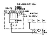
- a liquid supply system for a container includes a container transport / liquid ejecting apparatus including a transport apparatus that transports a container and a liquid ejecting apparatus that ejects liquid to the transported container. And a plurality of liquid supply means for supplying different types of liquid to the container transport / liquid ejecting apparatus, and a switching means for switching the plurality of liquid supply means, provided outside the container transport / liquid ejecting apparatus. And In the container liquid supply system, the liquid ejected to the container can be switched by the switching means provided outside the container transport / liquid ejecting apparatus, so that the system can be easily switched according to the purpose.
- the plurality of liquid supply means includes at least two of the following (A) to (D).
- the liquid supply system to the container can be appropriately switched according to the purpose as a system for sterilization or cleaning of the container.
- the container sterilization / cleaning system includes a sterilization unit and a cleaning unit provided with the liquid supply system to the container,
- the sterilization unit can switch between the medicine supply means or the sterile hot water supply means, and the washing unit can switch between the room temperature sterile water supply means or the low temperature sterile water supply means, and depending on the purpose of use, the sterilization unit and The liquid supply means of the cleaning unit is switched.
- the medicine supply means or sterilized hot water supply means of the sterilization unit provided with the liquid supply system, and the room temperature sterile water supply means or the low temperature sterile water supply means of the cleaning unit can be switched according to the purpose of use.
- the system can be used for many purposes.
- the switching means is a flow path switching valve.
- the spray liquid can be easily switched by adopting the above-described switching means.
- the container liquid supply system of the present invention it is possible to easily switch the jet liquid.
- the container liquid supply system of the present invention the container can be appropriately switched depending on the purpose as a system for sterilizing or cleaning the container.
- the container sterilization / washing system comprising the liquid supply system of the present invention, it is possible to select and carry out an optimum sterilization / washing process according to the type of container and the contents filled therein. Moreover, it becomes simpler by making these switchable using a switching valve.
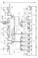
- FIG. 1 is an explanatory diagram showing a configuration of a container sterilization / cleaning system 100 according to the present invention.
- This container sterilization / washing system 100 shows a case where the container sterilization / washing system of the present invention is applied to an aseptic filling system for PET bottles.
- the container sterilization / cleaning system 100 for a plastic bottle includes a bottle supply unit 10 that sequentially supplies the plastic bottles to the sterilization process, a bottle sterilization unit 20 that sterilizes the plastic bottle received from the bottle supply unit 10, and a pet.
- a liquid supply system that supplies sterilization / cleaning liquid to the cleaning unit 30 is provided.
- the details of the liquid supply system will be described later with reference to FIG.
- the bottle sterilization unit 20 and the bottle cleaning unit 30 are configured by a wheel as a transport device, and a nozzle is provided via a flow path switching valve as a liquid ejection device for ejecting liquid to a plastic bottle provided at the outer peripheral end of the wheel. Connected to a plurality of types of liquid supply sources.
- the switching valve provided as the liquid supply switching means is provided outside the liquid ejecting apparatus 95. Therefore, when each liquid ejecting apparatus 95 is provided with a plurality of nozzles, all the liquid supply in the ejecting apparatus can be switched by one switching valve, which is convenient.
- the liquid supply switching means may be disposed inside the bottle sterilization section 20 and the bottle cleaning section 30 described later. However, when the liquid supply switching means is arranged outside as shown in the figure, when the maintenance of the switching means is performed, Since it is not necessary to enter into the sterilization part 20 and the bottle washing
- the bottle supply unit 10 sequentially supplies, for example, a PET bottle that has been biaxially stretch blow-molded from a preform to the bottle sterilization unit 20 while being gripped by, for example, a gripper (not shown) at the circumferential end of the transport wheel.
- the bottle conveyance method may be a known method, but in this embodiment, the neck grip conveyance method is adopted.
- the plastic bottle is reversed from the upright posture to the inverted posture and is transferred to the wheel of the bottle sterilization unit 20.
- the bottle sterilization unit 20 maintains a positive pressure state in which the internal pressure is slightly higher than the external air pressure in order to prevent intrusion of external air.
- the boundary with the bottle supply unit 10 is partitioned by an inner wall, and the inflow of outside air is blocked by flowing sterile air to the bottle supply unit 10 side at a PET bottle delivery point.
- the bottle sterilization unit 20 is composed of large and small wheels having different diameters, and in this embodiment, six large and small wheels.
- a drug, aseptic liquid as high temperature sterilized water necessary for sterilization; high temperature aseptic water
- nozzles (not shown) for injecting normal temperature aseptic water or low temperature aseptic water as necessary are provided.
- each nozzle is connected to a plurality of liquid supply sources via a flow path switching valve. Further, as will be described later, each nozzle has the longest liquid ejection time (the longest ON time of the nozzle injection valve) corresponding to the split angle of the wheel with respect to the predetermined conveyance speed of the PET bottle.
- the type of container and its filling Processing such as appropriate sterilization (further cleaning and cooling as necessary) according to the contents can be performed.
- a PET bottle with a medicine or aseptic hot water depends on the type of beverage (filled contents) filled in the PET bottle.
- low acid beverages such as barley tea and milk coffee with pH 4.6 or higher
- apply chemicals and among low acid beverages with pH 4.6 or higher, apply hot water sterilization for catechin green tea, oolong tea, mineral water, etc. Is preferred.
- hot water sterilization is preferably applied to acidic beverages having a pH of less than 4.6, such as sports beverages, fruit juice beverages, or fruit juice-containing gas beverages.
- carbonated beverages of acidic beverages having a pH of less than 4.6 since carbonic acid has an antibacterial effect, aseptic water washing can be applied at this sterilization section, and washing described later can be omitted.
- the bottle cleaning unit 30 is composed of four large and small wheels with different diameters.
- a nozzle (not shown) for spraying various sterilized water of normal temperature sterilized water or low temperature sterilized water as a spray liquid on the inner peripheral surface and / or outer peripheral surface of the bottle
- each nozzle has the longest liquid ejection time (the longest ON time of the nozzle injection valve) corresponding to the split angle of the wheel with respect to the predetermined conveyance speed of the PET bottle. Therefore, by appropriately combining large and small wheels and appropriately adjusting the ON time of the nozzle injection valve, it is possible to appropriately perform processing such as cooling, washing or rinsing according to the type of container and its filling content. It becomes.
- the filling and sealing unit 40 includes a filling machine (not shown) that fills a PET bottle with a predetermined amount of beverage via a filling line (liquid feeding line) that has been preliminarily heated and sterilized, and “sterilization treatment”. And a wrapping machine (not shown) for sealing the beverage-filled PET bottles with a “finished cap”.
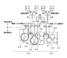
- FIG. 2 is an explanatory diagram showing a liquid supply system of the bottle sterilization unit 20 and the bottle cleaning unit 30 of the present invention.
- the sterilization nozzle injection valve or the washing nozzle injection valve of each wheel is taken out from the wheel and is simply displayed as a single valve.
- This liquid supply system includes a medicine supply source 50 for supplying medicine to each downstream sterilization nozzle, a sterile water supply source 60 for supplying sterile water to each downstream sterilization nozzle or each cleaning nozzle, and a sterilization nozzle injection valve
- the unit 70, the cleaning nozzle injection valve unit 80, and a valve control unit 90 for controlling ON / OFF and ON time of all the valves.
- the drug supply source 50 includes a drug tank 51 that stores a drug, a pump 52 that pumps the drug to each downstream nozzle, and a filter 53 that filters and purifies the drug.
- the drug for example, any one of peracetic acid, hydrogen peroxide, hypochlorous acid, ozone, hypochlorous acid (less than 200 ppm) is stored.
- the number of medicine tanks 51 is not limited to one.
- a plurality of medicine tanks 51 are provided, and different medicines are placed in each medicine tank 51 to supply each medicine later. It may be configured to be able to be switched by a flow path switching valve (for example, a flow path switching valve CV1).
- the sterile water supply source 60 is sterilized at a high temperature necessary for sterilization (temperature higher than normal temperature, preferably 64 ° C. or higher and 88 ° C. or lower with high sterilizing effect, more preferably 72 ° C. or higher and 88 ° C. or lower suitable for short-time sterilization).
- a high temperature sterile water tank 61 for storing warm water a normal temperature sterile water tank 62 for storing normal temperature sterile water (15 ° C. to 35 ° C.), and a low temperature sterile water tank for storing low temperature sterile water (over 0 ° C.
- normal temperature sterile water stored in the normal temperature sterile water tank 62 is generated by passing high temperature sterile water or low temperature sterile water therethrough, for example, by passing through a heat exchanger, or directly supplied, or as required. You may store in a tank like this.
- the flow path switching valve CV1 is a valve for switching the sterilization liquid supplied to the downstream side (sterilization nozzle injection valve unit 70). That is, one of the sterilizing liquid of the medicine or the high-temperature sterile water is supplied to the sterilizing nozzle injection valve unit 70 (excluding the sterilizing nozzle injection valve V5 described later) by the flow path switching valve CV1. The switching is performed by the valve control unit 90. Similarly, for the flow path switching valve CV2, the valve control unit 90 switches the flow path switching valve CV2 so that either one of the low-temperature aseptic water and the normal-temperature aseptic water is supplied to the cleaning nozzle injection valve unit 80. .
- the flow path switching valve CV3 controls the flow of the liquid supplied to the sterilizing nozzle injection valve V5 on the flow path switching valve CV1 side (: medicine or high-temperature sterile water) or the flow path as required by the control of the valve control unit 90. Switch to one of the liquids on the valve CV2 side (normal temperature sterile water or cryogenic sterile water).
- the shutoff valves SV1 and SV2 are valves that stop the supply of chemicals or sterile water to the downstream side. Therefore, it is normally open (normally open).
- the connecting valve SV3 shuts off the medicine supply source 50 and the sterile water supply source 60 (in this embodiment, the normal temperature sterile water tank 62 and the low temperature sterile water tank 63), and bottles normal temperature or low temperature sterile water as necessary. This is a valve for supplying the sterilizing unit 20 (or high-temperature aseptic water to the bottle cleaning unit 30), and is therefore normally closed (normally closed).
- this apparatus since this apparatus is used only for rinsing the bottle, when supplying normal temperature or low-temperature sterilized water to the bottle sterilization unit 20, the shut-off valve SV1 is closed (or the bottle is rinsed with high-temperature sterilized water. Supplying high-temperature sterile water to the bottle washing unit 30 is performed by switching the flow path switching valve CV1 to the high-temperature sterile water side and closing the shut-off valve SV2) to open the connection valve SV3.
- the sterilization nozzle injection valve unit 70 is opened while the valve control unit 90 corresponds to the wheel split angle, and a medicine or high-temperature sterile water is injected from the nozzle onto the inner peripheral surface and / or outer peripheral surface of the PET bottle.
- the injection nozzle may follow along with the wheel, or may be fixedly installed so that it can be appropriately injected within a range corresponding to the split angle without following, and it may be injected toward the plastic bottle while the apparatus is operating. Good.
- FIG. 3 is an explanatory diagram showing a form of a PET bottle sterilization / cleaning process.
- the PET bottle is sterilized with the chemical of the sterilization unit 20, and the PET bottle to which the chemical is adhered is rinsed with room temperature aseptic water of the cleaning unit 30.
- the flow path switching valve CV1 connects the flow path of the medicine 51 and the sterilization nozzle injection valves V1, V2, V3, V4 of the sterilization nozzle injection valve unit 70, and further, the sterilization nozzle injection valve V5 is connected to the flow path switching valve CV3. Is switched to the flow path switching valve CV1 side (drug side).
- the flow path switching valve CV2 connects the room temperature aseptic water 62 and the cleaning nozzle injection valves V6 and V7 of the cleaning nozzle injection valve unit 80.
- the connecting valve SV3 is closed.
- the sterilization unit 20 sterilizes the plastic bottle by simultaneously injecting the medicine with the internal injection and the external injection.
- the five wheels 21, 22, 23, 24, 25 are combined.
- wheel split angles ⁇ 1, ⁇ 2, ⁇ 3, ⁇ 4, ⁇ 5 corresponding to (corresponding to) ON of the sterilizing nozzle injection valve are set, and the injection time is set using the respective maximum wheel split angles.
- the valve control unit 90 opens the sterilizing nozzle injection valves V1, V2, V3, V4, and V5 while the PET bottle is moving along the conveyance path (indicated by a bold line in the figure) corresponding to the wheel split angle. Then, the medicine is injected from the sterilization nozzle into the PET bottle.
- the valve control unit 90 may select a valve that is normally closed from the sterilization nozzle injection valves (V1 to V5) and set the corresponding wheel not to inject the medicine.
- the split angles ⁇ 1 to ⁇ 5 may be set to be appropriately short within the maximum split angle range.
- the injection time can be increased or decreased by adjusting the PET bottle conveyance speed faster or slower, and it is also possible to adjust these appropriately by combining them. This time adjustment can also be applied to the cleaning nozzle injection valves (V6, V7).
- the attached drug is drained (discharged) and delivered to the bottle cleaning unit 30.
- normal temperature sterile water is jetted into the PET bottle to rinse away the medicine.
- two wheels 31 and 32 are combined as a combination of wheels, and the wheel allocation corresponding to (corresponding to) the ON time of the cleaning nozzle injection valve is selected as necessary for the selection of a wheel to be used for normal temperature sterile water injection.
- the valve control unit 90 opens the cleaning nozzle injection valves V6 and V7, and starts from the cleaning nozzle.
- Room temperature sterile water is injected into the PET bottle.
- the normal temperature aseptic water attached while the PET bottle is conveyed by the wheels 33 and 34 is drained and delivered to the filling and sealing unit 40 as shown in FIG.
- FIG. 4 is an explanatory diagram showing a form of another sterilization / washing process for PET bottles.
- the PET bottle is sterilized with the high temperature sterile water of the sterilization unit 20, and the high temperature PET bottle is cooled with the low temperature sterile water of the cleaning unit 30.
- the flow path switching valve CV1 connects the flow path of the high-temperature sterile water 61 and the sterilization nozzle injection valves V1, V2, V3, and V4 of the sterilization nozzle injection valve unit 70, and the sterilization nozzle injection valve V5 switches the flow path.
- the valve CV3 is connected by switching to the flow path switching valve CV1 side (high temperature sterile water side), while the flow path switching valve CV2 connects the flow path of the low temperature sterile water 63 and the washing nozzle injection valve units V6 and V7.
- the connecting valve SV3 is closed.
- the sterilization unit 20 sterilizes high-temperature sterile water by simultaneous injection of internal and external injections into a PET bottle.
- the sterilization nozzle injection valves V1 and V2 are always turned off, and the three wheels 23, 24 and 25 are used for hot water injection, and wheel injection angles ⁇ 3, ⁇ 4, and ⁇ 5 corresponding to (corresponding to) the ON time of the sterilization nozzle injection valve are set to the respective maximum wheel division angles and used to set the injection time.
- the valve control unit 90 opens the sterilization nozzle injection valves V3, V4, V5, and sterilizes the sterilization nozzle. Hot sterile water is sprayed from the nozzle into the plastic bottle.
- the attached high-temperature aseptic water is drained and delivered to the bottle cleaning unit 30.
- the cleaning unit 30 sprays low-temperature aseptic water onto the PET bottle, and cools the PET bottle heated at the above-described sterilization unit.
- the cleaning nozzle injection valve V7 is always OFF, the maximum wheel split angle ⁇ 1 corresponding to (corresponding to) the ON time of the cleaning nozzle injection valve is set for the wheel 31, and the PET bottle corresponds to the wheel split angle.
- the valve control unit 90 opens the cleaning nozzle injection valve V6 while the PET bottle is moving along the transport path, and the temperature is lowered from the cleaning nozzle.
- Aseptic water is injected into the plastic bottle.
- normal-temperature sterilized water may be used instead of the low-temperature sterilized water.
- FIG. 5 is an explanatory view showing another embodiment of the PET bottle sterilization / washing process.
- the sterilization / washing process is performed by sterilizing the PET bottle with the high temperature sterile water of the sterilization unit 20, cooling the high temperature PET bottle with the low temperature sterile water supplied to the sterilization unit 20, Cool with sterile water.
- the sterilization unit 20 sterilizes high-temperature sterile water by simultaneously injecting internal and external injections into a PET bottle.
- three wheels 22, 23, and 24 are used,
- the wheel split angles ⁇ 2, ⁇ 3, ⁇ 4 corresponding to (corresponding to) the ON time are set as the maximum wheel split angles, respectively, and the PET bottle moves along the transport path (indicated by the bold line in the figure) corresponding to the wheel split angle.
- the valve control unit 90 always turns off the sterilization nozzle injection valve V1, and sets the sterilization nozzle injection valves V2, V3, and V4 while the PET bottle is moving along the conveyance path of the wheels 22, 23, and 24.
- the sterilization nozzle is opened so that high temperature sterile water is sprayed onto the PET bottle.
- the wheel 25 is immediately sprayed with low-temperature aseptic water to cool the plastic bottle.
- the split angle ⁇ 5 is set to the maximum wheel split angle, and external injection is performed while draining the hot water in the plastic bottle. If necessary, low temperature aseptic water may be injected into the inside at the same time, and the hot water in the PET bottle may be cooled or replaced with cold water.
- the valve control unit 90 changes the flow path switching valve CV3 to the flow path switching valve CV2 side (low temperature sterilization).
- low temperature aseptic water is supplied to the sterilization nozzle injection valve V5.
- the sterilization nozzle injection valve V5 is opened, and low temperature aseptic water is injected from the sterilization nozzle into the PET bottle.
- the sterilized water adhering to the PET bottle is drained while being transported by the two wheels 25 and 26, and delivered to the bottle cleaning unit 30.
- the cleaning unit 30 further cools the PET bottle by spraying low-temperature aseptic water onto the PET bottle that has not been sufficiently cooled.
- the cleaning nozzle injection valve V7 is always OFF, the wheel split angle ⁇ 1 corresponding to (corresponding to) the injection time for the wheel 31 is set to the maximum wheel split angle, and the PET bottle is conveyed corresponding to the wheel split angle.
- the valve control unit 90 opens the cleaning nozzle injection valve V6 while the PET bottle is moving along the transport path, and is cold-sterilized from the cleaning nozzle. Water is injected into the plastic bottle.
- the sterilization nozzle and the cleaning nozzle provided at the outer peripheral end of each wheel as a transfer device are provided with a plurality of liquid supply sources via the flow path switching valves CV1, CV2, CV3. It is connected to the. Therefore, the combination of the wheel according to the processing content and time and each wheel split angle are determined, and the liquid supply source is switched by the flow path switching valves CV1, CV2, CV3, and while corresponding to the split angle of each wheel,
- the injection valves of the sterilization nozzle and the cleaning nozzle it becomes possible to carry out an optimal sterilization / cleaning process for the container according to the type of the container and the filling contents.
- FIG. 6 liquid to a container provided in a single serial transfer device A sterilization / cleaning system for a container provided with a plurality of liquid supply means and a means for switching between them is useful because the spray liquid can be easily switched.
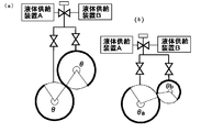
- FIG. 7A if at least two transport devices including a liquid ejecting apparatus are provided, a transport device that ejects liquid even when the liquid ejecting time of each liquid ejecting apparatus is fixed is selected. This is useful because the injection time can be changed. In the case of FIG.
- two kinds of changes can be made: ⁇ when one liquid ejecting apparatus is used, and 2 ⁇ when two liquid ejecting apparatuses are used.
- FIG. 7B when the liquid ejecting section width is different by two or more types in the transporting apparatus that ejects the liquid, the combination can be widened, and the types of time that can be set increase.
- three types of changes of ⁇ a, ⁇ b, and ⁇ a + ⁇ b can be made depending on the combination of the liquid ejecting apparatuses.
- the container sterilization / washing system of the present invention can be suitably applied to a container sterilization / washing process in an aseptic filling system for container-packed beverages.
Landscapes
- Engineering & Computer Science (AREA)
- Mechanical Engineering (AREA)
- Filling Of Jars Or Cans And Processes For Cleaning And Sealing Jars (AREA)
Abstract
Description
温水殺菌と薬剤殺菌はその殺菌性に違いがあるため、温水殺菌の適用はそのボトルに充填される内容物によって制限を受けることになる。例えば、pH4.6以上の低酸性飲料の中で温水殺菌を適用することが出来る充填内容物としては、カテキンで静菌性を有する緑茶飲料、ウーロン茶、ミネラルウォータ等が挙げられ、一方pH4.6以下の酸性飲料では果汁飲料、スポーツ飲料等が挙げられ、その他には充填後の流通温度を10℃以下にしたチルド飲料も対象となる。また、温水殺菌を適用することが出来ない充填内容物としては麦茶またはミルクコーヒー等がある。
このように充填システムの殺菌・洗浄工程を薬剤殺菌工程で組み立てた場合、充填内容物には制限がないものの、静菌性を有する充填内容物に対しても、必要のない薬剤殺菌を適用しなければならず、その結果余分なコストが発生することになる。一方、充填システムの殺菌・洗浄工程を温水殺菌工程で組み立てた場合、上述した通り、充填内容物に制限があり、適用することが出来ない充填内容物が存在する。この場合、薬剤殺菌を有する充填システムが別途必要となり、ボトルの殺菌・洗浄に係るコストが増大することになる。
ところで、回転体に等間隔で複数のボトルグリッパと、これら各グリッパに対応するノズルと、複数種類の流体(液体)をノズルに供給する複数の流体供給源と、ノズルと流体供給源との間の通路を断続するロータリバルブを備えたロータリ式洗浄装置が知られている(例えば、特許文献1を参照。)。このロータリ式洗浄装置は、ホイールの中心角の一部を一次洗浄領域、二次洗浄領域および水切り領域に各々割り当てて、ホイールの回転に伴ってボトルが一次洗浄領域または二次洗浄領域を通過する際に、ロータリバルブがノズルと流体との間の通路を順次接続して異なる流体をノズルに順次供給し、ボトルグリッパに保持されているボトルに異なる流体が順次噴射されるように構成されている。
しかし、上記ロータリ式洗浄装置では、下記の問題点を有している。例えば、一つのロータリ内で一次洗浄処理と二次洗浄処理を行うため、洗浄用流体によっては運転中の流体噴射ノズル内残留液の次に使用する洗浄流体への置換が困難で運用が難しくなる。また、洗浄流体変更により処理時間も変更する必要がある場合、噴射区間を決めるためのパーツ(特許文献1では長穴長さ変更のための固定プレート)を分解交換しなければならない。また、一次処理時間を長くしたい場合、対応するロータリの割り角(割り当てる角度幅)を変更(θ→θ':θ<θ')しなければならず、その結果、他方の二次処理時間が短くなるという問題点を有している。つまり、上記ロータリ式洗浄装置は、同一のロータリを複数の処理領域に分割し、容器の殺菌・洗浄処理を実施しているため、一次処理時間を長くする場合は必然的に二次処理時間は短くなるという問題点を有している。更に、ボトルを殺菌・洗浄する処理時間は、ロータリの回転速度と半径が一定の場合は、ロータリの割り角θに依存するため、結果的に処理時間の調整幅が狭いという問題点を有している。
そこで、本発明は、かかる従来技術の問題点に鑑みなされたものであって、その目的は、常に容器の種類およびその充填内容物に応じた最適な殺菌・洗浄工程を実施することができ、殺菌・洗浄に係る低コストを実現することが可能な容器の殺菌・洗浄システムを提供することにある。
前記容器の液体供給システムでは、容器搬送・液体噴射装置の外部に備えられた切換手段によって容器に噴射する液体を切り換えられるので、目的に応じて簡便にシステムを切り換えることが可能となる。
また、本発明の容器への液体供給システムでは、複数の液体供給手段が、以下の(A)~(D)のうちの少なくとも2種からなる。
(A)薬剤供給手段,(B)無菌温水供給手段,(C)常温無菌水供給手段,(D)低温無菌水供給手段。
前記容器への液体供給システムは、容器の殺菌または洗浄のためのシステムとして目的に応じ適宜切り換えて適用可能となる。
前記容器の殺菌・洗浄システムでは、液体供給システムを備える殺菌部の薬剤供給手段または無菌温水供給手段、及び洗浄部の常温無菌水供給手段または低温無菌水供給手段を使用目的に応じて切り換えることで、多用途に使用可能なシステムとなる。
上記容器の殺菌・洗浄システムでは、切換手段を上記構成とすることにより、簡便に噴射液を切り換え可能となる。
20 ボトル殺菌部
30 ボトル洗浄部
40 充填密封部
50 薬剤供給源
60 無菌水供給源
70 殺菌ノズル噴射弁ユニット
80 洗浄ノズル噴射弁ユニット
90 バルブ制御ユニット
100 容器の殺菌・洗浄システム
この容器の殺菌・洗浄システム100は、本発明の容器の殺菌・洗浄システムを、ペットボトルの無菌充填システムに適用した場合を示す。このペットボトルにおける容器の殺菌・洗浄システム100の構成は、ペットボトルを殺菌工程へ逐次供給するボトル供給部10と、ボトル供給部10から受け取ったペットボトルを殺菌処理するボトル殺菌部20と、ペットボトルを無菌水等で洗浄または冷却するボトル洗浄部30と、殺菌処理されたペットボトルに飲料を充填して「殺菌処理済みキャップ」にて密封する充填密封部40と、ボトル殺菌部20およびボトル洗浄部30に殺菌・洗浄液体を供給する液体供給系とを具備して構成されている。なお、液体供給系の詳細については、図2を参照しながら後述する。ボトル殺菌部20及びボトル洗浄部30は搬送装置としてホイールで構成され、さらにホイールの外周端部に設けられたペットボトルへ液体を噴射するための液体噴射装置として、ノズルが流路切換弁を介して複数の種類の液体供給源に接続されている。ここで、液体供給切換手段として設けられている切換弁は、液体噴射装置95の外部に設けられている。そのため、個々の液体噴射装置95に複数のノズルを備える場合、1つの切換弁でその噴射装置内全ての液体供給を切り換えられるので簡便である。なお、液体供給切換手段は、後述のボトル殺菌部20、ボトル洗浄部30内部に配置されていても良いが、図のように外部に配置された方が、切換手段のメンテナンスを行う際、ボトル殺菌部20、ボトル洗浄部30内に立ち入る必要がないため簡便にメンテナンスを行うことが出来るので好ましい。また、各ホイールにおいて斜線部で示されている範囲が、液体を噴射できる最長区間である。
この液体供給系統は、下流側の各殺菌ノズルへ薬剤を供給する薬剤供給源50と、下流側の各殺菌ノズルまたは各洗浄ノズルへ無菌水を供給する無菌水供給源60と、殺菌ノズル噴射弁ユニット70と、洗浄ノズル噴射弁ユニット80と、全てのバルブのON/OFF及びON時間を制御するバルブ制御ユニット90とから成る。
この殺菌・洗浄工程の形態は、ペットボトルを殺菌部20の薬剤で殺菌し、薬剤が付着したペットボトルを、洗浄部30の常温無菌水で濯ぐものである。従って、流路切換弁CV1は薬剤51の流路と殺菌ノズル噴射弁ユニット70の殺菌ノズル噴射弁V1,V2,V3,V4を接続し、さらに殺菌ノズル噴射弁V5とは、流路切換弁CV3を流路切換弁CV1側(薬剤側)に切り換えることで接続する。他方、流路切換弁CV2は常温無菌水62と洗浄ノズル噴射弁ユニット80の洗浄ノズル噴射弁V6,V7を接続する。また、連結弁SV3は閉とする。
最後に、ペットボトルをホイール33,34で搬送しながら付着した常温無菌水をドレンし、図2に示すように充填密封部40へ引き渡す。
この殺菌・洗浄工程の形態は、ペットボトルを殺菌部20の高温無菌水で殺菌し、この高温化したペットボトルを、洗浄部30の低温無菌水で冷却するものである。従って、流路切換弁CV1は高温無菌水61の流路と殺菌ノズル噴射弁ユニット70の殺菌ノズル噴射弁V1,V2,V3,V4を接続し、さらに殺菌ノズル噴射弁V5とは、流路切換弁CV3を流路切換弁CV1側(高温無菌水側)に切り換えることで接続し、他方、流路切換弁CV2は低温無菌水63の流路と洗浄ノズル噴射弁ユニットV6,V7を接続する。また、連結弁SV3は閉とする。
尚、前述した殺菌部20の高温無菌水によるペットボトルの加温が厳しくない場合は、低温無菌水の代わりに常温無菌水を使ってもよい。
この殺菌・洗浄工程の形態は、ペットボトルを殺菌部20の高温無菌水で殺菌し、この高温化したペットボトルを殺菌部20に供給した低温無菌水で冷却し、さらに、洗浄部30の低温無菌水で冷却するものである。
また、単一のシステムで容器の殺菌、洗浄、冷却または濯ぎに係る複数の処理を行うことが可能となり、殺菌・洗浄に係るコストが好適に低減する。
また、図7(a)に示すように液体噴射装置を備えた搬送装置も少なくとも2台備わっていれば、各液体噴射装置の液体噴射時間が固定されている場合でも液体噴射する搬送装置を選定することで噴射時間の変更が可能であり有用である。図7(a)の場合は、液体噴射装置を1台使用する場合のθと、2台使用する場合の2θの2通りの変更が可能である。さらに、図7(b)に示すように液体噴射区間幅が液体噴射する搬送装置で2種類以上異なっていると、組み合わせに幅ができ、設定できる時間の種類も増える。図7(b)の場合は液体噴射装置の組み合わせによってθa、θb、θa+θbの3通りの変更が可能である。
Claims (4)
- 容器を搬送する搬送装置と、搬送する前記容器に液体を噴射する液体噴射装置とから成る容器搬送・液体噴射装置を備え、
前記容器搬送・液体噴射装置に異なる種類の液体を供給する複数の液体供給手段と、該複数の液体供給手段を切り換える切換手段とを前記容器搬送・液体噴射装置の外部に備えたことを特徴とする、容器への液体供給システム。 - 前記複数の液体供給手段が、薬剤供給手段、無菌温水供給手段、常温無菌水供給手段、及び低温無菌水供給手段の内の少なくとも二種類の供給手段から成ることを特徴とする請求項1に記載の容器への液体供給システム。
- 請求項2に記載の容器への液体供給システムを備えた殺菌部及び洗浄部から成る容器の殺菌・洗浄システムであって、
前記殺菌部が薬剤供給手段または無菌温水供給手段を切り換え可能であり、
前記洗浄部が常温無菌水供給手段または低温無菌水供給手段を切り換え可能であって、
使用目的に応じて、前記殺菌部および洗浄部の液体供給手段を切り換えることを特徴とする容器の殺菌・洗浄システム。 - 前記切換手段は流路切換弁であることを特徴とする請求項1から3の何れかに記載の容器の殺菌・洗浄システム。
Priority Applications (3)
| Application Number | Priority Date | Filing Date | Title |
|---|---|---|---|
| JP2011515982A JP5641252B2 (ja) | 2009-05-26 | 2010-05-18 | 容器の殺菌・洗浄システム |
| KR1020117025759A KR101355046B1 (ko) | 2009-05-26 | 2010-05-18 | 용기의 살균·세정 시스템 |
| CN201080022755.1A CN102448870B (zh) | 2009-05-26 | 2010-05-18 | 容器的杀菌清洗系统 |
Applications Claiming Priority (2)
| Application Number | Priority Date | Filing Date | Title |
|---|---|---|---|
| JP2009-126395 | 2009-05-26 | ||
| JP2009126395 | 2009-05-26 |
Publications (1)
| Publication Number | Publication Date |
|---|---|
| WO2010137486A1 true WO2010137486A1 (ja) | 2010-12-02 |
Family
ID=43222597
Family Applications (1)
| Application Number | Title | Priority Date | Filing Date |
|---|---|---|---|
| PCT/JP2010/058316 Ceased WO2010137486A1 (ja) | 2009-05-26 | 2010-05-18 | 容器の殺菌・洗浄システム |
Country Status (4)
| Country | Link |
|---|---|
| JP (1) | JP5641252B2 (ja) |
| KR (1) | KR101355046B1 (ja) |
| CN (1) | CN102448870B (ja) |
| WO (1) | WO2010137486A1 (ja) |
Cited By (6)
| Publication number | Priority date | Publication date | Assignee | Title |
|---|---|---|---|---|
| CN103752555A (zh) * | 2014-01-03 | 2014-04-30 | 上海东富龙科技股份有限公司 | 一种用于洗瓶机的cip-sip系统 |
| WO2014077319A1 (ja) * | 2012-11-16 | 2014-05-22 | 大日本印刷株式会社 | 飲料充填装置の浄化方法 |
| CN106267262A (zh) * | 2015-06-05 | 2017-01-04 | 镇江市润州区孙氏翻醅机厂 | 玻璃瓶清洗杀菌机 |
| WO2017038584A1 (ja) * | 2015-09-04 | 2017-03-09 | 東洋製罐株式会社 | 無菌充填システム、容器殺菌ユニット、および無菌充填方法 |
| JP2018043189A (ja) * | 2016-09-14 | 2018-03-22 | 株式会社錢高組 | 液体噴出装置及び養生装置 |
| US11279606B2 (en) | 2016-09-30 | 2022-03-22 | Dai Nippon Printing Co., Ltd. | Sterile carbonated beverage filling system and sterile carbonated beverage filling method |
Families Citing this family (8)
| Publication number | Priority date | Publication date | Assignee | Title |
|---|---|---|---|---|
| KR101276418B1 (ko) | 2012-04-19 | 2013-06-18 | 황정빈 | 치아 임플란트 |
| CN104906611A (zh) * | 2015-06-12 | 2015-09-16 | 常州大学 | 一种塑料包装容器消毒杀菌的方法和装置 |
| CN108290729B (zh) * | 2015-12-22 | 2020-10-09 | 大日本印刷株式会社 | 杀菌处理的转换方法及产品充填装置 |
| CN105664206B (zh) * | 2016-01-28 | 2018-07-06 | 连云港佑源医药设备制造有限公司 | 一种集成压力式在线灭菌生产线 |
| CN106178748B (zh) * | 2016-07-26 | 2019-01-08 | 安徽天地高纯溶剂有限公司 | 一种新型高纯溶剂洗瓶装置 |
| CN106178749B (zh) * | 2016-07-26 | 2019-01-08 | 安徽天地高纯溶剂有限公司 | 一种便于长期使用的高纯溶剂洗瓶装置 |
| CN106140762A (zh) * | 2016-07-26 | 2016-11-23 | 安徽天地高纯溶剂有限公司 | 一种高纯溶剂瓶高效清洗装置 |
| JP6924423B2 (ja) * | 2019-12-04 | 2021-08-25 | 大日本印刷株式会社 | キャップ殺菌装置および内容物充填システム |
Citations (3)
| Publication number | Priority date | Publication date | Assignee | Title |
|---|---|---|---|---|
| JPH08267031A (ja) * | 1995-03-30 | 1996-10-15 | Shibuya Kogyo Co Ltd | ロータリ式洗浄装置 |
| JP2001106296A (ja) * | 1999-10-01 | 2001-04-17 | Kirin Brewery Co Ltd | 容器洗浄装置 |
| JP2008168930A (ja) * | 2007-01-12 | 2008-07-24 | Toyo Seikan Kaisha Ltd | 容器詰め飲料の製造方法 |
Family Cites Families (1)
| Publication number | Priority date | Publication date | Assignee | Title |
|---|---|---|---|---|
| DE19956186A1 (de) * | 1999-11-22 | 2001-05-23 | Krones Ag | Verfahren und Vorrichtung zum Sterilisieren von Verpackungsbehältern |
-
2010
- 2010-05-18 JP JP2011515982A patent/JP5641252B2/ja not_active Expired - Fee Related
- 2010-05-18 KR KR1020117025759A patent/KR101355046B1/ko active Active
- 2010-05-18 WO PCT/JP2010/058316 patent/WO2010137486A1/ja not_active Ceased
- 2010-05-18 CN CN201080022755.1A patent/CN102448870B/zh not_active Expired - Fee Related
Patent Citations (3)
| Publication number | Priority date | Publication date | Assignee | Title |
|---|---|---|---|---|
| JPH08267031A (ja) * | 1995-03-30 | 1996-10-15 | Shibuya Kogyo Co Ltd | ロータリ式洗浄装置 |
| JP2001106296A (ja) * | 1999-10-01 | 2001-04-17 | Kirin Brewery Co Ltd | 容器洗浄装置 |
| JP2008168930A (ja) * | 2007-01-12 | 2008-07-24 | Toyo Seikan Kaisha Ltd | 容器詰め飲料の製造方法 |
Cited By (16)
| Publication number | Priority date | Publication date | Assignee | Title |
|---|---|---|---|---|
| US10226796B2 (en) | 2012-11-16 | 2019-03-12 | Dai Nippon Printing Co., Ltd. | Method for cleaning drink filling system |
| WO2014077319A1 (ja) * | 2012-11-16 | 2014-05-22 | 大日本印刷株式会社 | 飲料充填装置の浄化方法 |
| EP2921450A4 (en) * | 2012-11-16 | 2016-08-31 | Dainippon Printing Co Ltd | Method for cleaning a beverage filling device |
| JPWO2014077319A1 (ja) * | 2012-11-16 | 2017-01-05 | 大日本印刷株式会社 | 飲料充填装置の浄化方法 |
| US11103899B2 (en) | 2012-11-16 | 2021-08-31 | Dai Nippon Printing Co., Ltd. | Method for cleaning drink filling system |
| US10888904B2 (en) | 2012-11-16 | 2021-01-12 | Dai Nippon Printing Co., Ltd. | Method for cleaning drink filling system |
| JP2018020848A (ja) * | 2012-11-16 | 2018-02-08 | 大日本印刷株式会社 | 飲料充填装置 |
| JP2018052623A (ja) * | 2012-11-16 | 2018-04-05 | 大日本印刷株式会社 | 飲料充填装置 |
| CN103752555A (zh) * | 2014-01-03 | 2014-04-30 | 上海东富龙科技股份有限公司 | 一种用于洗瓶机的cip-sip系统 |
| CN106267262A (zh) * | 2015-06-05 | 2017-01-04 | 镇江市润州区孙氏翻醅机厂 | 玻璃瓶清洗杀菌机 |
| CN107922074B (zh) * | 2015-09-04 | 2020-02-18 | 东洋制罐株式会社 | 无菌灌装系统、容器杀菌单元、以及无菌灌装方法 |
| CN107922074A (zh) * | 2015-09-04 | 2018-04-17 | 东洋制罐株式会社 | 无菌灌装系统、容器杀菌单元、以及无菌灌装方法 |
| JP2017047965A (ja) * | 2015-09-04 | 2017-03-09 | 東洋製罐株式会社 | 無菌充填システム、容器殺菌ユニット、および無菌充填方法 |
| WO2017038584A1 (ja) * | 2015-09-04 | 2017-03-09 | 東洋製罐株式会社 | 無菌充填システム、容器殺菌ユニット、および無菌充填方法 |
| JP2018043189A (ja) * | 2016-09-14 | 2018-03-22 | 株式会社錢高組 | 液体噴出装置及び養生装置 |
| US11279606B2 (en) | 2016-09-30 | 2022-03-22 | Dai Nippon Printing Co., Ltd. | Sterile carbonated beverage filling system and sterile carbonated beverage filling method |
Also Published As
| Publication number | Publication date |
|---|---|
| JPWO2010137486A1 (ja) | 2012-11-12 |
| CN102448870A (zh) | 2012-05-09 |
| CN102448870B (zh) | 2014-10-15 |
| JP5641252B2 (ja) | 2014-12-17 |
| KR20120041160A (ko) | 2012-04-30 |
| KR101355046B1 (ko) | 2014-01-24 |
Similar Documents
| Publication | Publication Date | Title |
|---|---|---|
| JP5641252B2 (ja) | 容器の殺菌・洗浄システム | |
| JP6044651B2 (ja) | 包装体の製造方法及び装置 | |
| KR101474893B1 (ko) | 용기의 살균, 세정 방법 | |
| CN115304011A (zh) | 无菌灌装装置及其净化方法 | |
| CN106115583A (zh) | 饮料填充装置 | |
| WO2019245019A1 (ja) | 炭酸飲料無菌充填システム、飲料充填システム及びcip処理方法 | |
| JP5974739B2 (ja) | 無菌充填用チャンバ内の滅菌方法及び装置 | |
| JP6849009B2 (ja) | 飲料充填システム及びcip処理方法 | |
| JP6860862B2 (ja) | 炭酸飲料無菌充填システム | |
| US12415713B2 (en) | Beverage filling system and CIP processing method | |
| JP6627918B2 (ja) | 炭酸飲料無菌充填システム | |
| US12473186B2 (en) | Beverage filling system and cip processing method | |
| JP7157936B2 (ja) | 飲料充填システム及びcip処理方法 | |
| JP7157937B2 (ja) | 飲料充填システム及びcip処理方法 | |
| JP6886642B2 (ja) | キャップ殺菌装置、内容物充填システム、キャップ殺菌方法および内容物充填方法 | |
| JP6886643B2 (ja) | キャップ殺菌装置、内容物充填システム、キャップ殺菌方法および内容物充填方法 | |
| JP6886644B2 (ja) | キャップ殺菌装置、内容物充填システム、キャップ殺菌方法および内容物充填方法 | |
| JP6788848B2 (ja) | キャップ殺菌装置、内容物充填システム、キャップ殺菌方法および内容物充填方法 | |
| JP2023175470A (ja) | 内容物充填システム及び処理方法 |
Legal Events
| Date | Code | Title | Description |
|---|---|---|---|
| WWE | Wipo information: entry into national phase |
Ref document number: 201080022755.1 Country of ref document: CN |
|
| 121 | Ep: the epo has been informed by wipo that ep was designated in this application |
Ref document number: 10780441 Country of ref document: EP Kind code of ref document: A1 |
|
| ENP | Entry into the national phase |
Ref document number: 2011515982 Country of ref document: JP Kind code of ref document: A |
|
| ENP | Entry into the national phase |
Ref document number: 20117025759 Country of ref document: KR Kind code of ref document: A |
|
| NENP | Non-entry into the national phase |
Ref country code: DE |
|
| 122 | Ep: pct application non-entry in european phase |
Ref document number: 10780441 Country of ref document: EP Kind code of ref document: A1 |