WO2010137403A1 - 液晶表示パネルの描画装置 - Google Patents
液晶表示パネルの描画装置 Download PDFInfo
- Publication number
- WO2010137403A1 WO2010137403A1 PCT/JP2010/055872 JP2010055872W WO2010137403A1 WO 2010137403 A1 WO2010137403 A1 WO 2010137403A1 JP 2010055872 W JP2010055872 W JP 2010055872W WO 2010137403 A1 WO2010137403 A1 WO 2010137403A1
- Authority
- WO
- WIPO (PCT)
- Prior art keywords
- gantry
- heads
- head
- undrawn
- display
- Prior art date
- Legal status (The legal status is an assumption and is not a legal conclusion. Google has not performed a legal analysis and makes no representation as to the accuracy of the status listed.)
- Ceased
Links
Images













Classifications
-
- G—PHYSICS
- G02—OPTICS
- G02F—OPTICAL DEVICES OR ARRANGEMENTS FOR THE CONTROL OF LIGHT BY MODIFICATION OF THE OPTICAL PROPERTIES OF THE MEDIA OF THE ELEMENTS INVOLVED THEREIN; NON-LINEAR OPTICS; FREQUENCY-CHANGING OF LIGHT; OPTICAL LOGIC ELEMENTS; OPTICAL ANALOGUE/DIGITAL CONVERTERS
- G02F1/00—Devices or arrangements for the control of the intensity, colour, phase, polarisation or direction of light arriving from an independent light source, e.g. switching, gating or modulating; Non-linear optics
- G02F1/01—Devices or arrangements for the control of the intensity, colour, phase, polarisation or direction of light arriving from an independent light source, e.g. switching, gating or modulating; Non-linear optics for the control of the intensity, phase, polarisation or colour
- G02F1/13—Devices or arrangements for the control of the intensity, colour, phase, polarisation or direction of light arriving from an independent light source, e.g. switching, gating or modulating; Non-linear optics for the control of the intensity, phase, polarisation or colour based on liquid crystals, e.g. single liquid crystal display cells
- G02F1/133—Constructional arrangements; Operation of liquid crystal cells; Circuit arrangements
- G02F1/1333—Constructional arrangements; Manufacturing methods
- G02F1/1339—Gaskets; Spacers; Sealing of cells
Definitions
- the present invention relates to a drawing apparatus that draws a seal pattern by supplying a sealant along the outline of a plurality of display portions formed on a substrate used in a liquid crystal display panel.
- liquid crystal display panels have been widely used as display means for home appliances such as computers and televisions.
- a liquid crystal display panel is formed by bonding a pair of glass substrates, which are a thin film transistor (TFT) array substrate and a color filter (CF) substrate, facing each other in parallel at a predetermined interval, and liquid crystal is interposed between the glass substrates. It has a sealed configuration.
- TFT thin film transistor
- CF color filter
- a plurality of TFTs and pixel electrodes are formed in a matrix on the TFT array substrate, a plurality of color filters are formed in a matrix on the CF substrate, and a common electrode is formed on almost the entire surface.
- An image can be displayed by controlling the liquid crystal by changing the voltage applied between the electrode and the common electrode.
- a display part for a plurality of liquid crystal display panels is formed on a large mother glass substrate (a large glass substrate for obtaining a plurality of liquid crystal display panels).
- a mother glass substrate a large glass substrate for obtaining a plurality of liquid crystal display panels.
- the sealing agent surrounds the TFT array substrate in which the TFTs and pixel electrodes are formed (display unit) or the CF substrate in which the color filter is formed (display unit). It is done to apply.
- liquid crystal is dropped on the region surrounded by the seal pattern P before the liquid crystal is dropped. Liquid crystal is sealed by bonding one substrate. Further, when forming a partially opened seal pattern P as shown in FIG. 25 (c), after bonding one substrate, liquid crystal is injected from an open portion (liquid crystal injection port) Pa, The liquid crystal is sealed by sealing the open portion Pa.
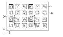
- Such a seal pattern P is formed by a drawing apparatus 30 as shown in FIG. As shown in the figure, the distance between the head 31 and the substrate 20 is kept constant while discharging the sealing agent from the head 31 filled with the sealing agent to the substrate 20 placed on the substrate stage 32, and the substrate stage.
- the seal pattern P along the outline of the display unit h can be drawn by horizontally moving the 32 relative to the head 31.
- the problem to be solved by the present invention is that even if a failure occurs in any one of a plurality of heads, another usable head is drawn with a seal pattern instead of the unusable head in which the failure has occurred. It is an object of the present invention to provide a drawing device for a liquid crystal display panel capable of performing the above.
- the present invention provides a first gantry and a second gantry that are long in the column direction and are arranged in a row direction above a substrate on which a plurality of display units arranged in a matrix in a lattice pattern are formed.
- a plurality of heads are provided in the first gantry and the second gantry along the column direction, respectively, while moving the first gantry and the second gantry relatively horizontally with respect to the substrate,
- a drawing device of a liquid crystal display panel for drawing a seal pattern along an outline of each display unit by a sealant simultaneously discharged from each head, and drawing by the unusable head when an unusable head occurs
- the gist of the invention is that the undrawn display portion that is scheduled to be provided is provided with alternative head allocating means for allocating usable heads instead of the unusable heads. It is.
- the alternative head allocating unit has a case where the number of usable heads other than the unusable heads in both the first gantry and the second gantry is larger than the number of columns of the plurality of display units arranged in a matrix. It is preferable that a usable head is assigned from a gantry in which the unusable head is present in the undrawn display portion.
- the alternative head allocating means includes both the first gantry and the second gantry on the undrawn display portion.
- the same number of usable heads are allocated and there are remaining undrawn display portions that are not allocated, it is possible to assign a usable head from one gantry to the remaining undrawn display portions. preferable.
- the alternative head allocating means has a case where different numbers of unusable heads exist in both the first gantry and the second gantry, and the number of rows of the plurality of display units arranged in a matrix is an even number.
- the same number of usable heads from both the first gantry and the second gantry are allocated to the undrawn display portion, and there are remaining undrawn display portions that are not allocated, the remaining undrawn display portion It is preferable that a head that can be used from one gantry is assigned to the drawing display unit.
- the alternative head allocating means different numbers of unusable heads exist in both the first gantry and the second gantry, and the number of rows of the plurality of display units arranged in a matrix is an odd number of 3 or more. In some cases, it is preferable that a head that can be used from one gantry is assigned to an undrawn display portion for one line, and a head that can be used from the other gantry is assigned to the remaining undrawn display portion.
- the alternative head allocating means is configured to perform the above operation when there is an unusable head in one of the first gantry and the second gantry and the number of rows of the plurality of display units arranged in a matrix is an even number.
- the remaining undrawn display unit Preferably, a usable head is allocated from one gantry.
- the alternative head allocating means is provided when there is an unusable head in one of the first gantry and the second gantry and the number of rows of the plurality of display units arranged in a matrix is an odd number of 3 or more.
- a head usable from one gantry is allocated to one line of the undrawn display portion, and a head usable from the other gantry is allocated to the remaining undrawn display portion.
- the display unit is configured with a plurality of color filters arranged in a matrix, or the display unit includes a plurality of thin film transistors arranged in a matrix. It is preferable that the structure is a pixel electrode, and further, the seal pattern is a closed pattern surrounding the outline of the display unit, or the seal pattern is partially open.
- the drawing device of the liquid crystal display panel having the above-described configuration, even if a failure occurs in any one of the plurality of heads, another usable head is replaced with a seal pattern instead of the unusable head in which the failure occurs. So that the production can be maintained until the unusable head is repaired or replaced at the end of the normal process of drawing a predetermined number of substrates without stopping the operation of the drawing device. This improves the production efficiency when a failure occurs in the head.
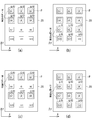
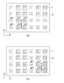
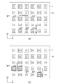
- FIG. 1 is an external perspective view showing a schematic configuration of a drawing apparatus according to an embodiment of the present invention. It is a block diagram which shows an example of control of the drawing apparatus of FIG. It is explanatory drawing which showed the procedure at the time of drawing 4x3 seal pattern with 2x3 head, (a) is explanatory drawing of 1st drawing, (b) is description of 2nd drawing.
- FIG. 4C is an explanatory diagram of the first drawing
- FIG. 4D is an explanatory diagram of the second drawing.
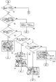
- FIG. 6 is a flowchart for explaining a procedure for assigning usable heads to an undrawn display portion that was planned to be drawn when both of the gantry A and B provided with 2 ⁇ 3 heads have unusable heads. is there. Flowchart for explaining a procedure for assigning usable heads to an undrawn display portion that was planned to be drawn when one of the gantry A, B having 2 ⁇ 3 heads has unusable heads.
- FIG. 8 is an explanatory diagram illustrating the next procedure of FIG. 7, where (a) is an explanatory diagram of the third drawing, and (b) is an explanatory diagram of the fourth drawing. It is explanatory drawing which showed the next procedure of FIG. 8, (a) is explanatory drawing of the 5th drawing, (b) is explanatory drawing of the 6th drawing.
- FIG. 5B is an explanatory diagram of the second drawing
- FIG. 5C is an explanatory diagram of the third drawing
- FIG. 6 is an explanatory diagram showing a procedure when 2 ⁇ 3 heads (heads A1, A2, and B1 are unusable heads) draw 4 ⁇ 6 seal patterns, and (a) shows the first to fourth times.
- Drawing explanatory drawing (b) is explanatory drawing of the 5th drawing. It is explanatory drawing which showed the next procedure of FIG.
- FIG. 6 is an explanatory diagram showing a procedure when 2 ⁇ 3 heads (heads A1, B1, and B2 are unusable heads) draw 5 ⁇ 6 seal patterns, and (a) shows the first to fourth times. Drawing explanatory drawing, (b) is explanatory drawing of the 5th drawing. It is explanatory drawing which showed the next procedure of FIG.
- FIG. 1 is a perspective view showing an embodiment of a drawing apparatus of the present invention.
- the X direction and the Y direction are directions indicated by arrows in FIG.
- the drawing apparatus 1 includes a substrate stage 2 for placing the substrate 20 in a horizontal state, a pair of frames 5 and 5 disposed in parallel to opposite sides of the substrate stage 2, There are provided two gantry A and B movably mounted on the frames 5 and 5 and a plurality of heads A1 to A3 and B1 to B3 which are attached to the gantry A and B and discharge a sealant.
- the substrate stage 2 includes a table 3 on which a substrate 20 such as a mother glass substrate for obtaining a plurality of liquid crystal display panels in which a plurality of display portions h are arranged in a matrix is placed, and the table 3 in the Y direction (display A table moving means 4 for moving in the row direction of the portion h (row direction) is provided, and the substrate stage 2 is provided on the upper surface of the gantry 8. Further, the substrate stage 2 includes a suction unit (not shown) that sucks the placed substrate 20, and the suction unit can fix and hold the substrate 20 on the placement surface of the table 3. Yes. For example, air suction means is used as the suction means.
- the gantry A, B has a gate-like shape that is long in the X direction (the arrangement direction of the columns of the display units h arranged in a matrix: the column direction (X direction)), and straddles the substrate stage 2. Is provided.
- the gantry A, B is moved on the frames 5, 5 by the gantry moving means 6, 6 provided on the frames 5, 5, in the Y direction (row arrangement direction of the display unit h arranged in a matrix: row direction (Y direction). ))
- Can be moved individually. Therefore, the gantry A, B can be moved in the approaching direction and the separating direction by the gantry moving means 6, 6. For example, the distance between the gantry A, B can be changed, or the gantry can be moved.
- gantry moving means 6 and 6 for example, a feed screw means using a servo motor as a driving source, a moving means using a linear motor as a driving source, or the like is used.
- the heads A1 to A3 and B1 to B3 can be individually moved in the X direction by a plurality of head moving means 7 provided in the gantry A and B.
- the heads A1, A2 and A3 provided on the gantry A can be moved in the approaching direction and the separating direction by the head moving means 7, for example, the heads A1, A2 and A3.
- the distance between A3 can be individually changed, or the heads A1, A2, and A3 can be moved in one direction while maintaining a predetermined distance.
- the heads B1, B2, and B3 provided on the gantry B can be moved in the approaching direction and the separating direction by the head moving means 7, for example, the heads B1,
- the distance between B2 and B3 can be changed individually, or the heads B1, B2 and B3 can be moved in one direction while maintaining a predetermined distance.
- the heads A1 to A3 and B1 to B3 have a storage cylinder 9 such as a syringe that stores the sealant, and a nozzle 10 that communicates with the storage cylinder 9 and discharges the sealant. Further, the storage cylinder 9 is connected to a gas supply unit via a gas supply tube (not shown) and the like, and the gas supplied to the storage cylinder 9 can discharge the sealing agent inside from the nozzle 10. It has become. For example, compressed air or compressed nitrogen is used as the gas supplied to the housing cylinder 9. The heads A1 to A3 and B1 to B3 are replaced with new heads every time the sealant in the housing cylinder 9 is used up.
- Such a drawing apparatus 1 includes a control means 11 as shown in FIG.
- the control means 11 controls the operations of the table moving means 4, the gantry moving means 6, the head moving means 7 and the ejection operations of the heads A1 to A3 and B1 to B3.
- the control means 11 is configured with an operation unit such as a PC (Personal Computer), a monitor, and a keyboard, for example, and includes a data input unit 12 and a storage unit 13. Data such as the shape, number, and arrangement of the seal pattern P drawn on the substrate 20 are input to the control means 11 via the data input unit 12.
- PC Personal Computer
- control means 11 reads out storage data such as the array information of the heads A1 to A3 and B1 to B3 stored in the storage unit 13, and based on the storage data and the input data input from the data input unit 12.
- the table moving means 4, the gantry moving means 6, the operation of the head moving means 7 and the ejection operations of the heads A1 to A3 and B1 to B3 are controlled, and the seal pattern to the substrate 20 placed on the stage 2 is controlled. P is drawn.
- the control means 11 includes an alternative head assignment means 14 described later.
- 4 ⁇ 3 display units h1 are provided by 2 ⁇ 3 (row ⁇ column, the same applies hereinafter) heads A1 to A3 and B1 to B3 provided in the drawing apparatus 1 as described above.
- a procedure for drawing the seal pattern P along the outline of h2, h3,... h10, h11, h12 will be described.
- the display portion h on which the seal pattern P is drawn is indicated by hatching so that the difference from the display portion h that is not drawn is easily understood.
- control means 11 controls the gantry moving means 6 and the head moving means 7 so that the heads A1 to A3 and B1 to B3 are displayed in 2 ⁇ 3 display units h1 and h2 in the first and second lines from the top. , H3, h4, h5, and h6.
- control means 11 controls the table moving means 4 and the head moving means 7 while discharging the sealant from the heads A1 to A3 and B1 to B3, thereby controlling the head A1.
- A3, B1 to B3 are moved in the X direction and the Y direction with respect to the substrate 20, so that 2 ⁇ 3 seal patterns P are similarly converted into 2 ⁇ 3 display portions h1, h2, h3, h4, h5. Drawing on h6 at the same time (first drawing).
- the control unit 11 controls the gantry moving unit 6 and the head moving unit 7 to start drawing the heads A1 to A3 and B1 to B3 on the 2 ⁇ 3 display units h7, h8, h9, h10, h11, and h12. Move to position. Then, as shown in FIG. 3B, the control means 11 controls the table moving means 4 and the head moving means 7 while discharging the sealant from the heads A1 to A3 and B1 to B3, thereby controlling the heads A1 to A3.
- 2 ⁇ 3 seal patterns P are similarly converted into 2 ⁇ 3 display portions h7, h8, h9, h10, h11, h12. Are simultaneously drawn (second drawing). As a result, the seal pattern P is drawn on all of the 4 ⁇ 3 display portions h1 to h12.
- the heads A1 to A3 of the gantry A are allocated to the display units h1 to h3 in the first row from the top, and the heads B1 to B3 of the gantry B are assigned to the third row from the top. Is assigned to the display portions h7 to h9, and the first drawing of the seal pattern P is performed.
- the heads A1 to A3 of the gantry A are in the second row from the top.
- the head B1 to B3 of the gantry B may be allocated to the display units h10 to h12 in the fourth row from the top to perform the second drawing of the seal pattern P.
- the two gantry A, B to which the heads A1-A3, B1-B3 are attached are provided, and the heads A1-A3, B1-B3 are provided by the table moving means 4 and the head moving means 7. Since the 2 ⁇ 3 seal patterns P are drawn simultaneously at the same time by moving them in synchronization, the time required for drawing can be reduced.
- the alternative head allocating unit 14 performs an unusable head setting operation for disabling the head A1.
- the unusable head setting operation is controlled so that the sealant is not discharged from the nozzle 10 of the unusable head A1.
- the alternative head allocating means 14 draws the seal pattern P in the first drawing as shown in FIG. 4A, which is the display unit that the unusable head A1 is supposed to draw.
- the alternative head assigning means 14 performs an alternative head assigning operation for assigning a head for drawing instead of the undrawn display portions h1 and h7.
- this alternative head allocation operation when there are a plurality of usable heads that can be drawn instead of the unusable head, the head that takes the shortest time for drawing to the undrawn display unit (drawing tact) is selected.
- the alternative head allocating means 14 is selected.
- the head A2 with the shorter drawing tact of the heads A2 and A3 of the gantry A is assigned to the undrawn display portion h1 as the usable alternative head, and the undrawn display portion h7 is assigned.
- the substitute head assigning means 14 assigns the head B1 having the shortest drawing tact among the heads B1 to B3 of the gantry B as usable substitute heads.
- the alternative head allocating means 14 may be configured to select the one with the smallest total number of drawing, that is, the one with the lowest usage frequency, when there are a plurality of alternative heads with the shortest drawing tact. As described above, when using a head that is replaced every time the sealant in the storage cylinder 9 is used up, if a specific head is selected and assigned as an alternative head, the head is replaced at an early stage. Because it becomes.
- step S1 it is determined whether there are unusable heads in both the gantry A and B. If there are unusable heads in both the gantry A and B (step S1 (Yes)), the number of usable heads in each of the gantry A and B in step S2 ⁇ the X direction (column direction) of the display unit h. It is determined whether the number of columns ⁇ . In the case of step S2 (No), usable heads are assigned instead of unusable heads (step S4).
- the display portion h is 4 ⁇ 2
- the number ⁇ of columns is 2
- the use of the head A3 and the gantry B not used by the gantry A is used instead of the unusable head A2 and the unusable head B2.
- step S3 it is determined in step S3 whether there are the same number of unusable heads in each of the gantry A and B.
- step S3 the same number of usable heads from each of the gantry A and B are allocated to the undrawn display portion (step S5). In this case, if there is a remaining undrawn display portion that is not assigned, a usable head of one gantry is assigned to the remaining undrawn display portion.
- FIGS. 7A and 7B show an example of such allocation and drawing procedures.
- 4 ⁇ 6 display portions h 1 to h 24 are formed on the substrate 20.
- the head A1 of the gantry A is an unusable head
- the head B1 of the gantry B is an unusable head.
- usable heads A2, A3, B2, and B3 are assigned to the display units h2, h3, h8, and h9 to perform the first drawing.
- FIG. 7B usable heads A2, A3, B2, and B3 are allocated to the display units h5, h6, h11, and h12, and the second drawing is performed.
- usable heads A2, A3, B2, and B3 are allocated to the display units h14, h15, h20, and h21, and the third drawing is performed.
- usable heads A2, A3, B2, and B3 are allocated to the display units h17, h18, h23, and h24, and the fourth drawing is performed.
- the display portions h1 and h7 are undrawn display portions where the unusable heads A1 and B1 were to draw the seal pattern P in the first drawing.
- the display portions h4 and h10 are undrawn display portions where the unusable heads A1 and B1 are scheduled to draw the seal pattern P in the second drawing.
- the display portions h13 and h19 are undrawn display portions where the unusable heads A1 and B1 are scheduled to draw the seal pattern P in the third drawing.
- the display portions h16 and h22 are undrawn display portions in which the unusable heads A1 and B1 are scheduled to draw the seal pattern P in the fourth drawing.
- the usable heads A2 and A3 of the gantry A are allocated to the undrawn display portions h1 and h4 in the same row, and the usable heads B2 and B2 of the gantry B are allocated.
- the fifth drawing is performed by assigning B3 to the undrawn display portions h13 and h16 having the same row.
- the usable heads A2 and A3 of the gantry A are allocated to the undrawn display portions h7 and h10 in the same row, and the usable head B2 of the gantry B is used.
- B3 are assigned to the undrawn display portions h19 and h22 having the same row, respectively, and the sixth drawing is performed.
- the seal pattern P is drawn on all of the 4 ⁇ 6 display portions h1 to h24.
- step S3 (No)
- step S3 that is, when the number of unusable heads of gantry A and B is not the same, for example, two unusable heads for gantry A, one unusable head for gantry B, etc.
- step S6 it is determined whether or not the number ⁇ of rows in the display portion h in the Y direction (row direction) is 1 or 2.
- FIG. 10A As shown in the figure, 2 ⁇ 3 display portions h1 to h6 are formed on the substrate 20.
- the heads A1, A2 of the gantry A are unusable heads
- the head B1 of the gantry B is unusable heads.
- usable heads A3, B2, and B3 are assigned to the display units h3, h5, and h6, and the first drawing is performed.
- the head A3 that can be used for the gantry A is allocated to the undrawn display portion h2, and the head that has the shorter drawing tact among the heads B2 and B3 that can be used for the gantry B.
- B2 is assigned to the undrawn display portion h4, and the second drawing is performed.
- the last remaining undrawn display portion h1 is assigned with the head A3 having the shortest drawing tact among the available heads A3, B2, and B3.
- the seal pattern P is drawn on all of the 2 ⁇ 3 display portions h1 to h6.
- step S6 it is determined in step S8 whether the number ⁇ of rows in the display portion h in the Y direction (row direction) is an even number (an even number of 4 or more).
- step S9 the same number of usable heads from each of the gantry A and B are allocated to the undrawn display portion. In this case, if there is a remaining undrawn display portion that is not assigned, a usable head of one gantry is assigned to the remaining undrawn display portion.
- FIGS. 11A An example of such allocation and drawing procedures will be described with reference to FIGS.
- 4 ⁇ 6 display portions h 1 to h 24 are formed on the substrate 20.
- the heads A1, A2 of the gantry A are unusable heads
- the head B1 of the gantry B is unusable heads.
- usable heads A3, B2, and B3 are assigned to the display units h3, h8, and h9 for the first drawing, and assigned to the display units h6, h11, and h12, and the second.
- the third drawing is assigned to the display units h15, h20, and h21 and the fourth drawing is assigned to the display units h18, h23, and h24.
- the display units h1, h2, and h7 are the undrawn display units, the display units h4, h5, and the unusable heads A1, A2, and B1 that are scheduled to draw the seal pattern P in the first drawing.
- h10 is an undrawn display portion where the unusable heads A1, A2 and B1 were to draw the seal pattern P in the second drawing, and display portions h13, h14 and h19 are unusable heads A1, A2 and B1.
- the undrawn display portion, the display portions h16, h17, and h22, which were scheduled to draw the seal pattern P in the third drawing, are scheduled to draw the seal pattern P in the unusable heads A1, A2, and B1 in the fourth drawing. This is an undrawn display portion.
- the usable head A3 of the gantry A is assigned to the undrawn display portion h2, and the usable head B2 of the gantry B is assigned to the undrawn display portion h7. Perform the second drawing.
- the usable head A3 of the gantry A is assigned to the undrawn display portion h5
- the usable head B2 of the gantry B is assigned to the undrawn display portion h10. Perform the second drawing.
- the usable head A3 of the gantry A is assigned to the undrawn display portion h14, and the usable head B2 of the gantry B is assigned to the undrawn display portion h19. Perform the second drawing.
- the usable head A3 of the gantry A is assigned to the undrawn display portion h17, and the usable head B2 of the gantry B is assigned to the undrawn display portion h22. Perform the second drawing.
- FIG. 13A After the eighth drawing, as shown in FIG. 13A, two undrawn display portions h1 and h4 are displayed on the first line from the top, and two undrawn display portions h13 and h16 are displayed on the third line from the top. Is left as the remaining undrawn display portion, so that the heads B2, B3 that can use one gantry B are allocated to the remaining undrawn display portions h1, h4, h13, and h16, and the other gantry A is used. Drawing is performed without assigning possible heads A3. Specifically, as shown in FIG. 13B, the usable heads B2 and B3 of the gantry B are allocated to the undrawn display portions h1 and h4 having the same row, and the ninth drawing is performed.
- the usable heads B2 and B3 of the gantry B are allocated to the undrawn display portions h13 and h16 having the same row, and the tenth drawing is performed. As a result, the seal pattern P is drawn on all of the 4 ⁇ 6 display portions h1 to h24.
- step S8 (No)
- step S10 all the lines are undrawn display portions.
- the usable heads are allocated so that the usable heads of one gantry are allocated to the undrawn display portion, and the usable heads of the other gantry are allocated to the remaining undrawn display portions.
- the substrate 20 has 5 ⁇ 6 display portions h1 to h30.
- the head A1 of the gantry A is an unusable head
- the heads B1 and B2 of the gantry B are unusable heads.
- usable heads A2, A3, and B3 are assigned to the display portions h2, h3, and h9 for the first drawing, and assigned to the display portions h5, h6, and h12, and the second.
- the third drawing is assigned to the display units h14, h15, and h21 and the fourth drawing is assigned to the display units h17, h18, and h24.
- the display units h1, h7, and h8 are the undrawn display units, the display units h4, h10, and the unusable heads A1, B1, and B2 that are scheduled to draw the seal pattern P in the first drawing.
- h11 indicates that the unusable heads A1, B1, and B2 are to draw the seal pattern P in the second drawing
- the undrawn display portions h13, h19, and h20 indicate that the unusable heads A1, B1, and B2
- the undrawn display portions, the display portions h16, h22, h23, which are scheduled to draw the seal pattern P in the third drawing, the unusable heads A1, B1, B2 draw the seal pattern P in the fourth drawing.
- the display parts h25 to h30 on the fifth line from the top are not undrawn display parts that the unusable heads A1, B1, and B2 are supposed to draw, but are certified as undrawn display parts.
- the usable heads A2 and A3 of the gantry A are allocated to the undrawn display portions h1 and h4 in the same row, and the usable head B3 of the gantry B is assigned 5
- the fifth drawing is performed by assigning to the undrawn display portion h25 in the line.
- the usable heads A2 and A3 of the gantry A are allocated to the undrawn display portions h7 and h8 in the same row, and the usable head B3 of the gantry B is 5
- the sixth drawing is performed by assigning to the undrawn display portion h26 in the line.
- the usable heads A2 and A3 of the gantry A are allocated to the undrawn display portions h10 and h11 in the same row, and the usable head B3 of the gantry B is assigned 5
- the seventh drawing is performed by assigning to the undrawn display portion h27 in the line.
- the usable heads A2 and A3 of the gantry A are allocated to the undrawn display portions h13 and h16 in the same row, and the usable head B3 of the gantry B is 5
- the eighth drawing is performed by assigning to the undrawn display portion h28 in the line.
- usable heads A2 and A3 of gantry A are allocated to undrawn display portions h19 and h20 in the same row, and usable heads B3 of gantry B are assigned 5
- the ninth drawing is performed by assigning to the undrawn display portion h29 in the line.
- the usable heads A2 and A3 of the gantry A are allocated to the undrawn display portions h22 and h23 in the same row, and the usable head B3 of the gantry B is assigned to the fifth row.
- the tenth drawing is performed by assigning to the undrawn display portion h30 in FIG. As a result, the seal pattern P is drawn on all of the 5 ⁇ 6 display portions h1 to h30.
- FIG. 6 is a flowchart when there is no unusable head in both gantry A and B in step S1 of the flowchart of FIG. 5, that is, when there is an unusable head in only one gantry (step S1 (No)). Show.
- step S1 whether the number of usable heads of each of the gantry A and B in step S11 ⁇ the number ⁇ of columns of the display unit h in the X direction (column direction)? Determined.
- step S11 usable heads are assigned instead of unusable heads (step S13).
- the unusable head A2 is scheduled to draw.
- the seal pattern P can be drawn on all the 4 ⁇ 2 display portions h by assigning the unused head A3 of the gantry A instead of the unusable head A2 to the undrawn display portion. it can.
- step S11 it is determined in step S12 whether the number ⁇ of rows in the display unit h in the Y direction (row direction) is 1 or 2.
- step S14 the usable head of one gantry having the unusable head is assigned to the undrawn display portion.
- FIG. 19A As shown in the figure, 2 ⁇ 3 display portions h1 to h6 are formed on the substrate 20.
- the head B1 of the gantry B is an unusable head.
- usable heads A1, A2, A3, B2, and B3 are allocated to the display units h1, h2, h3, h5, and h6, and the first drawing is performed.
- the head B2 with the shorter drawing tact is assigned to the undrawn display portion h4 and the second drawing is performed.
- the seal pattern P is drawn on all of the 2 ⁇ 3 display portions h1 to h6.
- step S12 (No)
- step S15 it is determined in step S15 whether or not the number ⁇ of rows in the display portion h in the Y direction (row direction) is an even number (an even number of 4 or more).
- step S18 the same number of usable heads from each of the gantry A and B are allocated to the undrawn display portion.
- FIG. 20 (a) As shown in the figure, 4 ⁇ 6 display portions h1 to h24 are formed on the substrate 20.
- the head B1 of the gantry B is an unusable head.
- usable heads A1, A2, A3, B2, and B3 are assigned to the display units h1, h2, h3, h8, and h9, and the first drawing and display unit h4 are displayed.
- the display unit h7 has the unusable head B1 scheduled to draw the seal pattern P in the first drawing
- the display unit h10 has the unusable head B1 drawn the second time.
- the undrawn display portion and the display portion h19, which were scheduled to draw the seal pattern P in FIG. 5, are displayed in the undrawn display portion and the display portion h22 where the unusable head B1 was scheduled to draw the seal pattern P in the third drawing.
- the unusable head B1 is a non-drawn display unit that is scheduled to draw the seal pattern P in the fourth drawing.
- the heads A1 and A2 having a short drawing tact are assigned to the undrawn display portions h7 and h10 having the same row.
- Both the heads B2 and B3 that can be used by the gantry B are assigned to the undrawn display portions h19 and h22, and the fifth drawing is performed.
- the seal pattern P is drawn on all of the 4 ⁇ 6 display portions h1 to h24.
- FIGS. 21 6 ⁇ 6 display portions h1 to h36 are formed on the substrate 20.
- the head B1 of the gantry B is an unusable head.
- usable heads A1, A2, A3, B2, and B3 are allocated to the display units h1, h2, h3, h8, and h9, and the first drawing and display unit h4 are displayed.
- the fifth drawing is assigned to the display units h25, h26, h27, h32, and h33, the fifth drawing is performed, and the display units h28, h29, h30, h35, and h36 are assigned to perform the sixth drawing.
- the display unit h7 has the unusable head B1 scheduled to draw the seal pattern P in the first drawing
- the display unit h10 has the unusable head B1 drawn the second time.
- the undrawn display portion and the display portion h19 which were scheduled to draw the seal pattern P in FIG. 5, are displayed in the undrawn display portion and the display portion h22 where the unusable head B1 was scheduled to draw the seal pattern P in the third drawing.
- the unusable head B1 is scheduled to draw the seal pattern P in the fourth drawing
- the display portion h31 is scheduled to draw the seal pattern P in the fifth drawing.
- the undrawn display portion and the display portion h34 are undrawn display portions in which the unusable head B1 is scheduled to draw the seal pattern P in the sixth drawing.
- the heads A1 and A2 having a short drawing tact are assigned to the undrawn display portions h7 and h10 having the same row.
- the usable heads B2 and B3 of the gantry B are assigned to the undrawn display portions h19 and h22 having the same row, and the seventh drawing is performed.
- the usable heads B2 and B3 of the gantry B with the shorter drawing tact are assigned to the undrawn display portions h31 and h34 having the same row, and the sixth drawing is performed.
- the seal pattern P is drawn on all of the 6 ⁇ 6 display portions h1 to h36.
- step S15 (No) the case of step S15 (No) will be described.
- this step S15 (No) that is, when the number ⁇ of rows in the display portion h in the Y direction (row direction) is an odd number (odd number of 3 or more)
- step S17 one row is all undrawn display portions.
- the usable heads are allocated so that the usable heads of one gantry are allocated to the undrawn display portion, and the usable heads of the other gantry are allocated to the remaining undrawn display portions.
- FIGS. 23 An example of such allocation and drawing procedures will be described with reference to FIGS.
- 5 ⁇ 6 display portions h1 to h30 are formed on the substrate 20.
- the head B1 of the gantry B is an unusable head.
- usable heads A1, A2, A3, B2, and B3 are assigned to the display units h1, h2, h3, h8, and h9, and the first drawing and display unit h4 are displayed.
- the display unit h7 has the unusable head B1 scheduled to draw the seal pattern P in the first drawing
- the display unit h10 has the unusable head B1 drawn the second time.
- the undrawn display portion and the display portion h19, which were scheduled to draw the seal pattern P in FIG. 5, are displayed in the undrawn display portion and the display portion h22 where the unusable head B1 was scheduled to draw the seal pattern P in the third drawing.
- the unusable head B1 is a non-drawn display unit that is scheduled to draw the seal pattern P in the fourth drawing.
- the display parts h25 to h30 on the fifth line from the top are not undrawn display parts that the unusable head B1 is scheduled to draw, but are certified as undrawn display parts.
- the heads A1 and A2 having a short drawing tact are assigned to the undrawn display portions h7 and h10 having the same row.
- the usable heads B2 and B3 of the gantry B are allocated to the undrawn display portions h25 and h26 on the fifth line, and the fifth drawing is performed.
- the usable heads A1 and A2 of the gantry A are allocated to the undrawn display portions h19 and h22 in the same row, and the usable heads B2 and B3 of the gantry B are used. Is assigned to the undrawn display portions h27 and h28 on the fifth line, and the sixth drawing is performed.
- the usable heads B2 and B3 of the gantry B are allocated to the undrawn display portions h29 and h30 on the fifth line, and the seventh drawing is performed.
- the seal pattern P is drawn on all of the 5 ⁇ 6 display portions h1 to h30.
- the column direction (the direction of the arrangement of the columns of the plurality of display units h arranged in a matrix) is arranged above the substrate 20 on which the plurality of display units h arranged in a matrix in a grid pattern is formed. )
- a long gantry A and a gantry B arranged in a row direction (a row arrangement direction of a plurality of display units h arranged in a matrix)
- each of the gantry A and the gantry B has a column direction.
- a plurality of heads are arranged side by side, and the seal pattern P along the outline of each display portion h is sealed by a sealant simultaneously ejected from each head while the gantry A and the gantry B are horizontally moved relative to the substrate 20.
- an unusable head occurs, an undrawn display portion that was scheduled to be drawn by the unusable head has a usable head instead of the unusable head. Since it is equipped with alternative head assignment means to attach, production can be maintained until the unusable head is repaired or replaced at the end of the normal process of drawing a predetermined number of substrates without stopping the operation of the drawing device Production efficiency is improved when a problem occurs in the head.
- drawing in the X direction in the seal pattern P is performed by moving the head by the head moving means 7 of the gantry A, B, and drawing in the Y direction is performed by the table moving means 4 of the substrate stage 2.
- the X direction drawing is performed by moving the table 3 in the X direction with the head fixed, and the Y direction drawing is performed with the table 3 fixed. This may be performed by moving the head in the Y direction in the state, and is not limited to the above-described embodiment.
Landscapes
- Physics & Mathematics (AREA)
- Nonlinear Science (AREA)
- Mathematical Physics (AREA)
- Chemical & Material Sciences (AREA)
- Crystallography & Structural Chemistry (AREA)
- General Physics & Mathematics (AREA)
- Optics & Photonics (AREA)
- Liquid Crystal (AREA)
Abstract
本発明は、複数のヘッドのうちのいずれかのヘッドに不具合が生じても、別の使用可能なヘッドが不具合が発生した使用不可ヘッドに代わりシールパターンの描画を行うことを可能とすることを目的とする。 本発明は、格子状に行列配置された複数の表示部が形成された基板の上方に、列方向に長尺な第1ガントリおよび第2ガントリが行方向に並んで設けられると共に、第1ガントリおよび第2ガントリにはそれぞれ列方向に沿って複数のヘッドが設けられ、基板に対して第1ガントリおよび第2ガントリを相対的に水平移動させながら、各ヘッドから同時に吐出されるシール剤によって各表示部にシールパターンを描画する描画装置であって、使用不可ヘッドが発生した際に、使用不可ヘッドによって描画される予定であった未描画表示部には該使用不可ヘッドの代わりに使用可能なヘッドを割り付ける代替ヘッド割付手段を備える。
Description
本発明は、液晶表示パネルに用いられている基板に形成された複数の表示部の外郭に沿ってシール剤を供給してシールパターンを描画する描画装置に関するものである。
近年、コンピュータやテレビなどの家電製品の表示手段として、液晶表示パネルが広く用いられている。液晶表示パネルは、一般には薄膜トランジスタ(TFT)アレイ基板とカラーフィルタ(CF)基板とからなる一対のガラス基板が所定の間隔を置いて平行に対向して貼り合わせられ、両ガラス基板間に液晶が封止された構成をなしている。
通常、TFTアレイ基板には複数のTFTおよび画素電極がマトリクス状に形成され、CF基板には複数のカラーフィルタがマトリクス状に形成されると共に、そのほぼ全面に共通電極が形成されており、画素電極と共通電極との間に印加する電圧を変化させて液晶を制御することで、画像を表示することができるようになっている。
このような液晶表示パネルを製造するにあたっては、大きなマザーガラス基板(液晶表示パネル複数個取り用の大型のガラス基板)に対して複数の液晶表示パネル分の表示部を形成するなど、製造工程の途中までは、マザーガラス基板のままで処理が行われており、その後、マザーガラス基板同士を貼り合わせて大判パネルとした後に個々に切断する方法か、または個々に切断してから貼り合わす方法が採用されている。
通常、基板同士の貼り合わせ前においては、TFTアレイ基板のTFTや画素電極が形成された領域(表示部)、またはCF基板のカラーフィルタが形成された領域(表示部)を囲むようにシール剤を塗布することが行われている。
この場合、図25(b)に示されるような表示部hを囲むような閉ループ形状を有するシールパターンPを形成する場合は、このシールパターンPで囲まれた領域に液晶を滴下してからもう一方の基板を貼り合わせることで、液晶を封止することが行われている。また、図25(c)に示されるような一部が開放されたシールパターンPを形成する場合は、一方の基板を貼り合わせた後に、開放部(液晶注入口)Paから液晶を注入し、開放部Paを密封することで、液晶を封止することが行われている。
このようなシールパターンPは、図25(a)に示されるような描画装置30によって形成される。図示されるように、シール剤が充填されたヘッド31から基板ステージ32上に載置された基板20に、シール剤を吐出しながら、ヘッド31と基板20との距離を一定に保ち、基板ステージ32をヘッド31に対して相対的に水平移動させることにより、表示部hの外郭に沿ったシールパターンPを描画することができる。
この場合、図示されるようにヘッド31を複数用意して、複数の表示部hに対して同時に複数のシールパターンPを描画することで、描画に要する時間の短縮が図られている(下記特許文献1参照)。
しかしながら、このような複数のヘッドを備えた描画装置において、いずれかのヘッドにノズル詰まりによる吐出不良などの不具合が生じる場合がある。このような場合、不具合が発生した使用不可ヘッドを取り外して修理するか、新品のヘッドと交換することが行われるのであるが、その間、描画装置の稼働を停止することになってしまうため生産効率が悪いという問題がある。
そこで、本発明が解決しようとする課題は、複数のヘッドのうちのいずれかのヘッドに不具合が生じても、別の使用可能なヘッドが、不具合が発生した使用不可ヘッドの代わりシールパターンの描画を行うことが可能な液晶表示パネルの描画装置を提供することである。
上記課題を解決するため本発明は、格子状に行列配置された複数の表示部が形成された基板の上方に、列方向に長尺な第1ガントリおよび第2ガントリが行方向に並んで設けられると共に、前記第1ガントリおよび第2ガントリにはそれぞれ列方向に沿って複数のヘッドが並んで設けられ、前記基板に対して前記第1ガントリおよび第2ガントリを相対的に水平移動させながら、前記各ヘッドから同時に吐出されるシール剤によって前記各表示部の外郭に沿ったシールパターンを描画する液晶表示パネルの描画装置であって、使用不可ヘッドが発生した際に、前記使用不可ヘッドによって描画される予定であった未描画表示部には該使用不可ヘッドの代わりに使用可能なヘッドを割り付ける代替ヘッド割付手段を備えることを要旨とするものである。
この場合、前記代替ヘッド割付手段は、前記第1ガントリと第2ガントリの双方において使用不可ヘッド以外の使用可能なヘッドの数が、行列配置された前記複数の表示部の列の数より多い場合は、前記未描画表示部には使用不可ヘッドが存在するガントリから使用可能なヘッドを割り付ける構成にするのが好ましい。
また、前記代替ヘッド割付手段は、前記第1ガントリと第2ガントリの双方に同数の使用不可ヘッドが存在する場合は、前記未描画表示部には前記第1ガントリと前記第2ガントリの双方から同数の使用可能なヘッドを割り付けると共に、割り付けられていない残余の未描画表示部が存在する場合は、該残余の未描画表示部には一方のガントリから使用可能なヘッドを割り付ける構成にするのが好ましい。
更に、前記代替ヘッド割付手段は、前記第1ガントリと第2ガントリの双方に異なる数の使用不可ヘッドが存在すると共に、行列配置された前記複数の表示部の行の数が偶数である場合は、前記未描画表示部には前記第1ガントリと前記第2ガントリの双方から同数の使用可能なヘッドを割り付けると共に、割り付けられていない残余の未描画表示部が存在する場合は、該残余の未描画表示部には一方のガントリから使用可能なヘッドを割り付ける構成にするのが好ましい。
そして、前記代替ヘッド割付手段は、前記第1ガントリと第2ガントリの双方に異なる数の使用不可ヘッドが存在すると共に、行列配置された前記複数の表示部の行の数が3以上の奇数である場合には、一行分の未描画表示部には一方のガントリから使用可能なヘッド割り付けると共に、残りの未描画表示部には他方のガントリから使用可能なヘッドを割り付ける構成にするのが好ましい。
また、前記代替ヘッド割付手段は、前記第1ガントリと第2ガントリの一方に使用不可ヘッドが存在すると共に、行列配置された前記複数の表示部の行の数が偶数である場合は、前記未描画表示部には前記第1ガントリと前記第2ガントリの双方から同数の使用可能なヘッドを割り付けると共に、割り付けられていない残余の未描画表示部が存在する場合は、該残余の未描画表示部には一方のガントリから使用可能なヘッドを割り付ける構成にするのが好ましい。
更に、前記代替ヘッド割付手段は、前記第1ガントリと第2ガントリの一方に使用不可ヘッドが存在すると共に、行列配置された前記複数の表示部の行の数が3以上の奇数である場合には、前記未描画表示部の一行分には一方のガントリから使用可能なヘッド割り付けると共に、残りの未描画表示部には他方のガントリから使用可能なヘッドを割り付ける構成にするのが好ましい。
そして、このような液晶表示パネルの描画装置において、前記表示部は、マトリクス状に配設された複数のカラーフィルタである構成や、前記表示部は、マトリクス状に配設された複数の薄膜トランジスタおよび画素電極である構成、更には、前記シールパターンは、前記表示部の外郭を囲む閉鎖されたパターンである構成や、前記シールパターンは、一部が開放されている構成にするのが好ましい。
上記構成を有する液晶表示パネルの描画装置によれば、複数のヘッドのうちのいずれかのヘッドに不具合が生じても、別の使用可能なヘッドが、不具合が発生した使用不可ヘッドの代わりシールパターンの描画を行うことが可能になっているので、描画装置の稼働を停止することなく、所定枚数の基板を描画する通常の工程の終了時に使用不可ヘッドを修理または交換するまで、生産を維持することができ、ヘッドに不具合が発生したときの生産効率が向上する。
以下に、本発明に係る液晶表示パネルの描画装置の実施の形態ついて、図面を参照して詳細に説明する。
図1は本発明の描画装置の一実施形態を示す斜視図である。尚、以下の説明で用いるX方向、Y方向は同図において矢印で示す方向である。
図示されるように描画装置1は、基板20を水平状態に載置するための基板ステージ2と、この基板ステージ2の相対する側辺に平行に配設された一対のフレーム5,5と、このフレーム5,5上に移動可能に取り付けられた2つのガントリA,Bと、このガントリA,Bに取り付けられ、シール剤を吐出する複数のヘッドA1~A3,B1~B3とを備える。
基板ステージ2は、複数の表示部hが格子状に行列配置された液晶表示パネル複数個取り用のマザーガラス基板などの基板20が載置されるテーブル3と、このテーブル3をY方向(表示部hの行の並び方向:行方向)に移動させるテーブル移動手段4を備えており、この基板ステージ2は架台8の上面に設けられている。また、基板ステージ2は、載置された基板20を吸着する図示しない吸着手段を備えており、この吸着手段によりテーブル3の載置面に基板20を固定して保持することが可能になっている。尚、吸着手段としては、例えばエアー吸着手段が用いられている。
ガントリA,Bは、X方向(行列配置された表示部hの列の並び方向:列方向(X方向))に長尺な門型の形状を有しており、基板ステージ2を跨ぐように設けられている。また、ガントリA,Bは、フレーム5,5に設けられたガントリ移動手段6,6によってフレーム5,5上をY方向(行列配置された表示部hの行の並び方向:行方向(Y方向))にそれぞれ個別に移動可能となっている。したがって、ガントリA,Bは、ガントリ移動手段6,6によってそれぞれが接近する方向および離間する方向に移動させることが可能になっており、例えば、ガントリA,B間の距離を変更したり、ガントリA,B間を所定の距離に維持しながら一方向に移動させたりすることができるようになっている。このようなガントリ移動手段6,6としては、例えばサーボモータを駆動源とする送りネジ手段やリニアモータを駆動源とする移動手段等が用いられている。
また、ヘッドA1~A3,B1~B3は、ガントリA,Bに設けられた複数のヘッド移動手段7によってX方向に個別に移動可能となっている。この場合、ガントリAに設けられたヘッドA1,A2,A3は、各ヘッド移動手段7によってそれぞれが接近する方向および離間する方向に移動させることが可能になっており、例えば、ヘッドA1,A2,A3間の距離を個別に変更したり、ヘッドA1,A2,A3間を所定の距離に維持しながら一方向に移動させたりすることができるようになっている。
また、同様に、ガントリBに設けられたヘッドB1,B2,B3は、各ヘッド移動手段7によってそれぞれが接近する方向および離間する方向に移動させることが可能になっており、例えば、ヘッドB1,B2,B3間の距離を個別に変更したり、ヘッドB1,B2,B3間を所定の距離に維持しながら一方向に移動させたりすることができるようになっている。このようなヘッド移動手段7としては、例えばサーボモータを駆動源とする送りネジ手段やリニアモータを駆動源とする移動手段等が用いられている。
ヘッドA1~A3,B1~B3は、シール剤を収容するシリンジ等の収容筒9と、その収容筒9に連通してシール剤を吐出するノズル10を有している。また、収容筒9には、図示しない気体供給チューブ等を介して気体供給部に接続されており、収容筒9に供給される気体により、その内部のシール剤をノズル10から吐出することが可能になっている。このような収容筒9に供給される気体としては、例えば圧縮空気や圧縮窒素等が用いられる。尚、ヘッドA1~A3,B1~B3は、収容筒9内のシール剤を使い切る毎に、新たなヘッドと交換されるようになっている。
このような描画装置1は、図2に示されるような制御手段11を備えている。図示されるように制御手段11は、上述したテーブル移動手段4と、ガントリ移動手段6と、ヘッド移動手段7の動作およびヘッドA1~A3,B1~B3の吐出動作を制御する。制御手段11は、例えばPC(Personal Computer)、モニタ、キーボードなどの操作部を備えたもので構成されており、データ入力部12と記憶部13を有している。この制御手段11には、基板20に描画されるシールパターンPの形状や個数、配列などのデータがデータ入力部12を介して入力されるようになっている。
この場合、制御手段11は、記憶部13に記憶されているヘッドA1~A3,B1~B3の配列情報などの記憶データを読み出し、この記憶データとデータ入力部12から入力された入力データに基づいて、テーブル移動手段4と、ガントリ移動手段6と、ヘッド移動手段7の動作およびヘッドA1~A3,B1~B3の吐出動作を制御して、ステージ2に載置された基板20へのシールパターンPの描画を行わせるようになっている。尚、制御手段11は後述する代替ヘッド割付手段14を備えている。
次に、このような描画装置1が備える2×3(行×列、以下同じ)個のヘッドA1~A3,B1~B3により、図3に示されるような4×3個の表示部h1,h2,h3,・・・h10,h11,h12の外郭に沿ったシールパターンPを描画する手順について説明する。尚、以下に説明する図面において、シールパターンPが描画された表示部hについてはハッチングを記載して、描画されていない表示部hとの違いが分かりやすいようにされている。
先ず、制御手段11は、ガントリ移動手段6とヘッド移動手段7を制御してヘッドA1~A3,B1~B3を、上から1行目と2行目にある2×3の表示部h1,h2,h3,h4,h5,h6の描画開始位置にまで移動させる。次に、制御手段11は、図3(a)に示されるように、ヘッドA1~A3,B1~B3からシール剤を吐出させながら、テーブル移動手段4とヘッド移動手段7を制御してヘッドA1~A3,B1~B3を基板20に対してX方向およびY方向に移動させることにより2×3個のシールパターンPを、同じく2×3個の表示部h1,h2,h3,h4,h5,h6に同時に描画する(第1回目描画)。
次に、この第1回目描画の後も、上から3行目と4行目にある2×3個の表示部h7,h8,h9,h10,h11,h12にシールパターンPが描画されていないので、制御手段11は、ガントリ移動手段6とヘッド移動手段7を制御してヘッドA1~A3,B1~B3を、2×3の表示部h7,h8,h9,h10,h11,h12の描画開始位置にまで移動させる。そして、制御手段11は、図3(b)に示されるように、ヘッドA1~A3,B1~B3からシール剤を吐出させながら、テーブル移動手段4とヘッド移動手段7を制御してヘッドA1~A3,B1~B3を基板20に対してX方向およびY方向に移動させることにより2×3個のシールパターンPを、同じく2×3個の表示部h7,h8,h9,h10,h11,h12に同時に描画する(第2回目描画)。これにより4×3個の表示部h1~h12の全てにシールパターンPが描画される。
尚、図3(c)に示されるようにガントリAのヘッドA1~A3を、上から1行目にある表示部h1~h3に割り付けると共に、ガントリBのヘッドB1~B3を上から3行目にある表示部h7~h9に割り付けてシールパターンPの第1回目描画を行い、次に、図3(d)に示されるようにガントリAのヘッドA1~A3を、上から2行目にある表示部h4~h6に割り付けると共に、ガントリBのヘッドB1~B3を上から4行目にある表示部h10~h12に割り付けてシールパターンPの第2回目描画を行う構成にしても良い。
このような描画装置1によれば、ヘッドA1~A3,B1~B3が取り付けられた2つのガントリA,Bを設けると共に、テーブル移動手段4とヘッド移動手段7によりヘッドA1~A3,B1~B3を同期して移動させることによって、2×3個のシールパターンPを一度に同時に描画する構成なので、描画に要する時間の短縮を図ることが可能になっている。
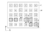
次に、制御手段11が備える代替ヘッド割付手段14の動作の手順について図4を用いて説明する。データ入力部12から例えばヘッドA1にノズル詰まりなどの不具合が発生した情報が入力されると、代替ヘッド割付手段14は、このヘッドA1を使用不可にする使用不可ヘッド設定動作を行う。この使用不可ヘッド設定動作としては、使用不可ヘッドA1のノズル10からシール剤が吐出されないように制御される。
次に、代替ヘッド割付手段14は、使用不可ヘッドA1が描画する予定であった表示部、具体的には図4(a)に示されるように第1回目描画でシールパターンPが描画される予定であった表示部h1と、図4(b)に示されるように第2回目描画でシールパターンPが描画される予定であった表示部h7を未描画表示部として認定する未描画表示部認定動作を行う。
そして、代替ヘッド割付手段14は、未描画表示部h1およびh7に対して代わりに描画を行うヘッドを割り付ける代替ヘッド割付動作を行う。この代替ヘッド割付動作においては、使用不可ヘッドの代わりに描画できる使用可能なヘッドが複数ある場合には未描画表示部への描画のための移動に要する時間(描画タクト)が最短となるヘッドが代替ヘッド割付手段14によって選択されるようになっている。
例えば図4(c)に示されるように、未描画表示部h1には使用可能な代替ヘッドとしてガントリAのヘッドA2,A3のうち描画タクトが短い方のヘッドA2を割り付け、未描画表示部h7には使用可能な代替ヘッドとしてガントリBのヘッドB1~B3のうち描画タクトが最も短くなるヘッドB1を割り付けることが代替ヘッド割付手段14によって行われる。
尚、代替ヘッド割付手段14は、描画タクトが最短になる代替ヘッドが複数ある場合は、トータルの描画回数が最も少ないもの、つまり使用頻度の最も低いものを選択する構成にしても良い。上述したように収容筒9内のシール剤を使い切る毎に交換するタイプのヘッドを用いている場合は、ある特定のヘッドばかりを代替ヘッドとして選択して割り付けると、そのヘッドを早期に交換することになってしまうからである。
次に、図5および図6に示されるフローチャートを用いて、上述した2つのガントリA,Bにそれぞれ設けられた複数のヘッドにおいてノズル詰まりなどの不具合が発生した使用不可ヘッドがある場合に、その使用不可ヘッドがシールパターンを描画する予定であった未描画表示部に対して使用可能なヘッドを、代替ヘッド割付手段14が割付ける様々な手順について説明する。
先ず、図5に示されるフローチャートについて説明する。図示されるように、先ずステップS1では、ガントリA,Bの双方に使用不可ヘッドがあるか判定される。ガントリA,Bの双方に使用不可ヘッドがある場合(ステップS1(Yes))は、ステップS2においてガントリA,Bのそれぞれの使用可能なヘッドの数<X方向(列方向)の表示部hの列の数αであるか判定される。ステップS2(No)の場合は、使用不可ヘッドの代わりに使用可能なヘッドが割付けられる(ステップS4)。
例えば、ガントリAのヘッドA2が使用不可ヘッド、ガントリBのヘッドB2が使用不可ヘッドであっても、表示部hが4×2個である場合は、列の数αが2であることから、使用不可ヘッドA2と使用不可ヘッドB2が描画する予定であった未描画表示部には、この使用不可ヘッドA2と使用不可ヘッドB2の代わりにガントリAの使用していないヘッドA3とガントリBの使用していないヘッドB3を割付けることで4×2個の表示部hの全てにシールパターンPを描画することができる。
次に、ステップS2(Yes)の場合は、ステップS3でガントリA,Bのそれぞれに同数の使用不可ヘッドがあるか判定される。ステップS3(Yes)の場合は、ガントリA,Bのそれぞれから同数の使用可能なヘッドを未描画表示部に割り付ける(ステップS5)。この場合、割り付けられていない残余の未描画表示部がある場合は、その残余の未描画表示部には一方のガントリの使用可能なヘッドを割り付ける。
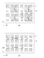
このような割り付けと描画の手順の例を、図7~図9を用いて説明する。図示されるように基板20には4×6個の表示部h1~h24が形成されている。この場合、ガントリAのヘッドA1が使用不可ヘッド、ガントリBのヘッドB1が使用不可ヘッドである。先ず、図7(a)に示されるように使用可能なヘッドA2,A3,B2,B3を、表示部h2,h3,h8,h9に割り付けて第1回目描画を行う。次に、図7(b)に示されるように使用可能なヘッドA2,A3,B2,B3を、表示部h5,h6,h11,h12に割り付けて第2回目描画を行う。
次に、図8(a)に示されるように使用可能なヘッドA2,A3,B2,B3を、表示部h14,h15,h20,h21に割り付けて第3回目描画を行う。次に、図8(b)に示されるように使用可能なヘッドA2,A3,B2,B3を、表示部h17,h18,h23,h24に割り付けて第4回目描画を行う。
この場合、図8(b)に示されるように、表示部h1,h7が、使用不可ヘッドA1,B1が第1回目描画でシールパターンPを描画する予定であった未描画表示部である。また、表示部h4,h10が、使用不可ヘッドA1,B1が第2回目描画でシールパターンPを描画する予定であった未描画表示部である。更に、表示部h13,h19が、使用不可ヘッドA1,B1が第3回目描画でシールパターンPを描画する予定であった未描画表示部である。そして、表示部h16,h22が、使用不可ヘッドA1,B1が第4回目描画でシールパターンPを描画する予定であった未描画表示部である。
次に、図9(a)に示されるようにガントリAの使用可能なヘッドA2,A3を行が同じである未描画表示部h1,h4のそれぞれ割り付けると共に、ガントリBの使用可能なヘッドB2,B3を行が同じである未描画表示部h13,h16にそれぞれ割り付けて第5回目描画を行う。そして、最後に図9(b)に示されるようにガントリAの使用可能なヘッドA2,A3を行が同じである未描画表示部h7,h10のそれぞれ割り付けると共に、ガントリBの使用可能なヘッドB2,B3を行が同じである未描画表示部h19,h22にそれぞれ割り付けて第6回目描画を行う。これにより4×6個の表示部h1~h24の全てにシールパターンPが描画される。
次にステップS3(No)の場合について説明する。このステップS3(No)の場合、つまり例えばガントリAに使用不可ヘッドが2個、ガントリBに使用不可ヘッドが1個などのようにガントリA,Bのそれぞれの使用不可ヘッドが同数でない場合は、ステップS6においてY方向(行方向)の表示部hの行の数βが1または2であるか判定される。ステップS6(Yes)の場合は、ステップS7でβ=1のときは使用不可ヘッドが少ない方のガントリから使用可能ヘッドを未描画表示部に割り付ける。また、β=2のときはガントリA,Bのそれぞれから同数の使用可能なヘッドを未描画表示部に割り付ける。この場合、割り付けられていない残余の未描画表示部がある場合は、その残余の未描画表示部には一方のガントリの使用可能なヘッドを割り付ける。
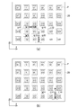
このような割り付けと描画の手順の例を、図10を用いて説明する。図示されるように基板20には2×3個の表示部h1~h6が形成されている。この場合、ガントリAのヘッドA1,A2が使用不可ヘッド、ガントリBのヘッドB1が使用不可ヘッドである。先ず、図10(a)に示されるように使用可能なヘッドA3,B2,B3を、表示部h3,h5,h6に割り付けて第1回目描画を行う。
次に、図10(b)に示されるようにガントリAの使用可能なヘッドA3を未描画表示部h2に割り付ける共に、ガントリBの使用可能なヘッドB2,B3のうち描画タクトが短い方のヘッドB2を未描画表示部h4に割り付けて第2回目描画を行う。そして、図10(c)に示されるように最後に残った未描画表示部h1には、使用可能なヘッドA3,B2,B3のうち描画タクトが最も短いヘッドA3を割り付けて描画を行う。これにより2×3個の表示部h1~h6の全てにシールパターンPが描画される。
次に、ステップS6(No)の場合について説明する。このステップS6(No)の場合は、ステップS8においてY方向(行方向)の表示部hの行の数βが偶数(4以上の偶数)であるか判定される。ステップS8(Yes)の場合は、ステップS9においてガントリA,Bのそれぞれから同数の使用可能なヘッドを未描画表示部に割り付ける。この場合、割り付けられていない残余の未描画表示部がある場合は、その残余の未描画表示部には一方のガントリの使用可能なヘッドを割り付ける。
このような割り付けと描画の手順の例を、図11~図14を用いて説明する。図示されるように基板20には4×6個の表示部h1~h24が形成されている。この場合、ガントリAのヘッドA1,A2が使用不可ヘッド、ガントリBのヘッドB1が使用不可ヘッドである。先ず、図11(a)に示されるように使用可能なヘッドA3,B2,B3を、表示部h3,h8,h9に割り付けて第1回目描画、表示部h6,h11,h12に割り付けて第2回目描画、表示部h15,h20,h21に割り付けて第3回目描画、表示部h18,h23,h24に割り付けて第4回目描画を行う。
図示されるように、表示部h1,h2,h7が、使用不可ヘッドA1,A2,B1が第1回目描画でシールパターンPを描画する予定であった未描画表示部、表示部h4,h5,h10が、使用不可ヘッドA1,A2,B1が第2回目描画でシールパターンPを描画する予定であった未描画表示部、表示部h13,h14,h19が、使用不可ヘッドA1,A2,B1が第3回目描画でシールパターンPを描画する予定であった未描画表示部、表示部h16,h17,h22が、使用不可ヘッドA1,A2,B1が第4回目描画でシールパターンPを描画する予定であった未描画表示部である。
次に、図11(b)に示されるようにガントリAの使用可能なヘッドA3を未描画表示部h2に割り付けると共に、ガントリBの使用可能なヘッドB2を未描画表示部h7に割り付けて第5回目描画を行う。次に、図12(a)に示されるようにガントリAの使用可能なヘッドA3を未描画表示部h5に割り付ける共に、ガントリBの使用可能なヘッドB2を未描画表示部h10に割り付けて第6回目描画を行う。
次に、図12(b)に示されるようにガントリAの使用可能なヘッドA3を未描画表示部h14に割り付けると共に、ガントリBの使用可能なヘッドB2を未描画表示部h19に割り付けて第7回目描画を行う。次に、図13(a)に示されるようにガントリAの使用可能なヘッドA3を未描画表示部h17に割り付けると共に、ガントリBの使用可能なヘッドB2を未描画表示部h22に割り付けて第8回目描画を行う。
この第8回目描画の後においては、図13(a)に示されるように上から一行目に2つの未描画表示部h1,h4、上から3行目に2つの未描画表示部h13,h16が残余の未描画表示部として残っているので、この残余の未描画表示部h1,h4,h13,h16には一方のガントリBの使用可能なヘッドB2,B3を割り付け、他方のガントリAの使用可能なヘッドA3は割り付けないで描画を行う。具体的には、図13(b)に示されるようにガントリBの使用可能なヘッドB2,B3を行が同じである未描画表示部h1,h4に割り付けて第9回目描画を行う。そして、最後に図14に示されるようにガントリBの使用可能なヘッドB2,B3を行が同じである未描画表示部h13,h16に割り付けて第10回目描画を行う。これにより4×6個の表示部h1~h24の全てにシールパターンPが描画される。
次に、ステップS8(No)の場合について説明する。このステップS8(No)の場合、つまりY方向(行方向)の表示部hの行の数βが奇数(3以上の奇数)である場合は、ステップS10において一行分が全て未描画表示部となるように使用可能なヘッドを割り付けると共に、その未描画表示部には、一方のガントリの使用可能なヘッドを割り付け、残りの未描画表示部には他方のガントリの使用可能なヘッドを割り付ける。
このような割り付けと描画の手順の例を、図15~図18を用いて説明する。図示されるように基板20には5×6個の表示部h1~h30が形成されている。この場合、ガントリAのヘッドA1が使用不可ヘッド、ガントリBのヘッドB1,B2が使用不可ヘッドである。先ず、図15(a)に示されるように使用可能なヘッドA2,A3,B3を、表示部h2,h3,h9に割り付けて第1回目描画、表示部h5,h6,h12に割り付けて第2回目描画、表示部h14,h15,h21に割り付けて第3回目描画、表示部h17,h18,h24に割り付けて第4回目描画を行う。
図示されるように、表示部h1,h7,h8が、使用不可ヘッドA1,B1,B2が第1回目描画でシールパターンPを描画する予定であった未描画表示部、表示部h4,h10,h11が、使用不可ヘッドA1,B1,B2が第2回目描画でシールパターンPを描画する予定であった未描画表示部、表示部h13,h19,h20が、使用不可ヘッドA1,B1,B2が、第3回目描画でシールパターンPを描画する予定であった未描画表示部、表示部h16,h22,h23が、使用不可ヘッドA1,B1,B2が第4回目描画でシールパターンPを描画する予定であった未描画表示部である。また、上から5行目の表示部h25~h30は、使用不可ヘッドA1,B1,B2が描画する予定であった未描画表示部ではないが、未描画表示部として認定されている。
次に、図15(b)に示されるようにガントリAの使用可能なヘッドA2,A3を行が同じである未描画表示部h1,h4に割り付ける共に、ガントリBの使用可能なヘッドB3を5行目にある未描画表示部h25に割り付けて第5回目描画を行う。次に、図16(a)に示されるようにガントリAの使用可能なヘッドA2,A3を行が同じである未描画表示部h7,h8に割り付ける共に、ガントリBの使用可能なヘッドB3を5行目にある未描画表示部h26に割り付けて第6回目描画を行う。
次に、図16(b)に示されるようにガントリAの使用可能なヘッドA2,A3を行が同じである未描画表示部h10,h11に割り付ける共に、ガントリBの使用可能なヘッドB3を5行目にある未描画表示部h27に割り付けて第7回目描画を行う。次に、図17(a)に示されるようにガントリAの使用可能なヘッドA2,A3を行が同じである未描画表示部h13,h16に割り付ける共に、ガントリBの使用可能なヘッドB3を5行目にある未描画表示部h28に割り付けて第8回目描画を行う。
次に、図17(b)に示されるようにガントリAの使用可能なヘッドA2,A3を行が同じである未描画表示部h19,h20に割り付ける共に、ガントリBの使用可能なヘッドB3を5行目にある未描画表示部h29に割り付けて第9回目描画を行う。そして最後に、図18に示されるようにガントリAの使用可能なヘッドA2,A3を行が同じである未描画表示部h22,h23に割り付ける共に、ガントリBの使用可能なヘッドB3を5行目にある未描画表示部h30に割り付けて第10回目描画を行う。これにより5×6個の表示部h1~h30の全てにシールパターンPが描画される。
次に、図6のフローチャートについて説明する。図6は、図5のフローチャートのステップS1において、ガントリA,Bの双方に使用不可ヘッドがない場合、つまり一方のガントリにだけ使用不可ヘッドがある場合(ステップS1(No))についてのフローチャートを示している。
図示されるように、ステップS1(No)の場合は、ステップS11においてガントリA,Bのそれぞれの使用可能なヘッドの数<X方向(列方向)の表示部hの列の数αであるか判定される。ステップS11(No)の場合は、使用不可ヘッドの代わりに使用可能なヘッドが割付けられる(ステップS13)。
例えば、一方のガントリAのヘッドA2が使用不可ヘッドであっても、表示部hが4×2個ある場合は、列の数αが2であることから、使用不可ヘッドA2が描画する予定であった未描画表示部には、この使用不可ヘッドA2の代わりにガントリAの使用していないヘッドA3を割付けることで4×2個の表示部hの全てにシールパターンPを描画することができる。
次にステップS11(Yes)の場合について説明する。このステップS11(Yes)の場合は、ステップS12においてY方向(行方向)の表示部hの行の数βが1または2であるか判定される。ステップS12(Yes)の場合は、ステップS14において使用不可ヘッドがある一方のガントリの使用可能なヘッドを未描画表示部に割り付ける。
このような割り付けと描画の手順の例を、図19を用いて説明する。図示されるように基板20には2×3個の表示部h1~h6が形成されている。この場合、ガントリBのヘッドB1が使用不可ヘッドである。先ず、図19(a)に示されるように使用可能なヘッドA1,A2,A3,B2,B3を、表示部h1,h2,h3,h5,h6に割り付けて第1回目描画を行う。
次に、図10(b)に示されるようにガントリBの使用可能なヘッドB2,B3のうち描画タクトが短い方のヘッドB2を未描画表示部h4に割り付けて第2回目描画を行う。これにより2×3個の表示部h1~h6の全てにシールパターンPが描画される。
次に、ステップS12(No)の場合について説明する。このステップS12(No)の場合は、ステップS15においてY方向(行方向)の表示部hの行の数βが偶数(4以上の偶数)であるか判定される。ステップS15(Yes)の場合は、更にステップS16においてβ/2が偶数(β=4,8,12,・・・)であるか判定される。ステップS16(Yes)の場合は、ステップS18においてガントリA,Bのそれぞれから同数の使用可能なヘッドを未描画表示部に割り付ける。
このような割り付けと描画の手順の例を、図20を用いて説明する。図示されるように基板20には4×6個の表示部h1~h24が形成されている。この場合、ガントリBのヘッドB1が使用不可ヘッドである。先ず、図20(a)に示されるように使用可能なヘッドA1,A2,A3,B2,B3を、表示部h1,h2,h3,h8,h9に割り付けて第1回目描画、表示部h4,h5,h6,h11,h12に割り付けて第2回目描画、表示部h13,h14,h15,h20,h21に割り付けて第3回目描画、表示部h16,h17,h18,h23,h24に割り付けて第4回目描画を行う。
図示されるように、表示部h7が、使用不可ヘッドB1が第1回目描画でシールパターンPを描画する予定であった未描画表示部、表示部h10が、使用不可ヘッドB1が第2回目描画でシールパターンPを描画する予定であった未描画表示部、表示部h19が、使用不可ヘッドB1が第3回目描画でシールパターンPを描画する予定であった未描画表示部、表示部h22が、使用不可ヘッドB1が第4回目描画でシールパターンPを描画する予定であった未描画表示部である。
次に、図20(b)に示されるようにガントリAの使用可能なヘッドA1,A2,A3のうち描画タクトが短いヘッドA1,A2を行が同じである未描画表示部h7,h10に割り付ける共に、ガントリBの使用可能なヘッドB2,B3を未描画表示部h19,h22に割り付けて第5回目描画を行う。これにより4×6個の表示部h1~h24の全てにシールパターンPが描画される。
次に、ステップS16(No)の場合について説明する。ステップS16においてβ/2が偶数(β=4,8,12,・・・)でない場合、つまりβ=6,10,14,・・・である場合は、ステップS19においてガントリA,Bのそれぞれから同数の使用可能なヘッドを未描画表示部に割り付ける。この場合、割り付けられていない残余の未描画表示部には一方のガントリの使用可能なヘッドを割り付ける。
このような割り付けと描画の手順の例を、図21~図22を用いて説明する。図示されるように基板20には6×6個の表示部h1~h36が形成されている。この場合、ガントリBのヘッドB1が使用不可ヘッドである。先ず、図21(a)に示されるように使用可能なヘッドA1,A2、A3,B2,B3を、表示部h1,h2,h3,h8,h9に割り付けて第1回目描画、表示部h4,h5,h6,h11,h12に割り付けて第2回目描画、表示部h13,h14,h15,h20,h21に割り付けて第3回目描画、表示部h16,h17,h18,h23,h24に割り付けて第4回目描画、表示部h25,h26,h27,h32,h33に割り付けて第5回目描画、表示部h28,h29,h30,h35,h36に割り付けて第6回目描画を行う。
図示されるように、表示部h7が、使用不可ヘッドB1が第1回目描画でシールパターンPを描画する予定であった未描画表示部、表示部h10が、使用不可ヘッドB1が第2回目描画でシールパターンPを描画する予定であった未描画表示部、表示部h19が、使用不可ヘッドB1が第3回目描画でシールパターンPを描画する予定であった未描画表示部、表示部h22が、使用不可ヘッドB1が第4回目描画でシールパターンPを描画する予定であった未描画表示部、表示部h31が、使用不可ヘッドB1が第5回目描画でシールパターンPを描画する予定であった未描画表示部、表示部h34が、使用不可ヘッドB1が第6回目描画でシールパターンPを描画する予定であった未描画表示部である。
図示されるように行が同じである未描画表示部h7,h10、同じく行が同じである未描画表示部h19,h22、同じく行が同じである未描画表示部h31,h34というように2つの未描画表示部がある行の数が3行、つまり奇数行になっているので、2行分の未描画表示部についてはガントリA,Bの使用可能なヘッドを割り付け、残り1行分の未描画表示部には一方のガントリの使用可能なヘッドを割り付けることになる。
そこで、図21(b)に示されるようにガントリAの使用可能なヘッドA1、A2,A3のうち描画タクトが短いヘッドA1,A2を行が同じである未描画表示部h7,h10に割り付ける共に、ガントリBの使用可能なヘッドB2,B3を行が同じである未描画表示部h19,h22に割り付けて第7回目描画を行う。そして最後に、図22に示されるように描画タクトが短い方のガントリBの使用可能なヘッドB2,B3を行が同じである未描画表示部h31,h34に割り付けて第6回目描画を行う。これにより6×6個の表示部h1~h36の全てにシールパターンPが描画される。
次に、ステップS15(No)の場合について説明する。このステップS15(No)の場合、つまりY方向(行方向)の表示部hの行の数βが奇数(3以上の奇数)である場合は、ステップS17において一行分が全て未描画表示部となるように使用可能なヘッドを割り付けると共に、その未描画表示部には、一方のガントリの使用可能なヘッドを割り付け、残りの未描画表示部には他方のガントリの使用可能なヘッドを割り付ける。
このような割り付けと描画の手順の例を、図23および図24を用いて説明する。図示されるように基板20には5×6個の表示部h1~h30が形成されている。この場合、ガントリBのヘッドB1が使用不可ヘッドである。先ず、図23(a)に示されるように使用可能なヘッドA1,A2,A3,B2,B3を、表示部h1,h2,h3,h8,h9に割り付けて第1回目描画、表示部h4,h5,h6,h11,h12に割り付けて第2回目描画、表示部h13,h14,h15,h20,h21に割り付けて第3回目描画、表示部h16,h17,h18,h23,h24に割り付けて第4回目描画を行う。
図示されるように、表示部h7が、使用不可ヘッドB1が第1回目描画でシールパターンPを描画する予定であった未描画表示部、表示部h10が、使用不可ヘッドB1が第2回目描画でシールパターンPを描画する予定であった未描画表示部、表示部h19が、使用不可ヘッドB1が第3回目描画でシールパターンPを描画する予定であった未描画表示部、表示部h22が、使用不可ヘッドB1が第4回目描画でシールパターンPを描画する予定であった未描画表示部である。また、上から5行目の表示部h25~h30は、使用不可ヘッドB1が描画する予定であった未描画表示部ではないが、未描画表示部として認定されている。
次に、図23(b)に示されるようにガントリAの使用可能なヘッドA1,A2,A3のうち描画タクトが短いヘッドA1,A2を行が同じである未描画表示部h7,h10に割り付ける共に、ガントリBの使用可能なヘッドB2,B3を5行目にある未描画表示部h25,h26に割り付けて第5回目描画を行う。次に、図24(a)に示されるようにガントリAの使用可能なヘッドA1,A2を行が同じである未描画表示部h19,h22に割り付ける共に、ガントリBの使用可能なヘッドB2,B3を5行目にある未描画表示部h27,h28に割り付けて第6回目描画を行う。
そして最後に、図24(b)に示されるようにガントリBの使用可能なヘッドB2,B3を5行目にある未描画表示部h29,h30に割り付けて第7回目描画を行う。これにより5×6個の表示部h1~h30の全てにシールパターンPが描画される。
以上説明した描画装置1によれば、格子状に行列配置された複数の表示部hが形成された基板20の上方に、列方向(行列配置された複数の表示部hの列の並びの方向)に長尺なガントリAおよびガントリBが行方向(行列配置された複数の表示部hの行の並びの方向)に並んで設けられると共に、ガントリAおよびガントリBにはそれぞれ列方向に沿って複数のヘッドが並んで設けられ、基板20に対してガントリAおよびガントリBを相対的に水平移動させながら、各ヘッドから同時に吐出されるシール剤によって各表示部hの外郭に沿ったシールパターンPを描画する場合において、使用不可ヘッドが発生した際に、使用不可ヘッドによって描画される予定であった未描画表示部には該使用不可ヘッドの代わりに使用可能なヘッドを割り付ける代替ヘッド割付手段を備えているので、描画装置の稼働を停止することなく、所定枚数の基板を描画する通常の工程の終了時に使用不可ヘッドを修理または交換するまで、生産を維持することができ、ヘッドに不具合が発生したときの生産効率が向上する。
以上、本発明の一実施形態について説明したが、本発明はこうした実施形態に何ら限定されるものではなく、本発明の要旨を逸脱しない範囲において、種々なる態様で実施できることは勿論である。例えば、上述した描画装置1では、シールパターンPにおけるX方向の描画はガントリA,Bのヘッド移動手段7によってヘッドを移動させることによって行い、またY方向の描画は基板ステージ2のテーブル移動手段4によってテーブル3を移動させることによって行う構成について説明したが、X方向の描画を、ヘッドを固定してテーブル3をX方向に移動させることによって行い、またY方向の描画を、テーブル3を固定した状態でヘッドをY方向に移動させることによって行っても良く、上述した実施の形態には限定されない。
Claims (11)
- 格子状に行列配置された複数の表示部が形成された基板の上方に、列方向に長尺な第1ガントリおよび第2ガントリが行方向に並んで設けられると共に、前記第1ガントリおよび第2ガントリにはそれぞれ列方向に沿って複数のヘッドが並んで設けられ、前記基板に対して前記第1ガントリおよび第2ガントリを相対的に水平移動させながら、前記各ヘッドから同時に吐出されるシール剤によって前記各表示部の外郭に沿ったシールパターンを描画する液晶表示パネルの描画装置であって、使用不可ヘッドが発生した際に、前記使用不可ヘッドによって描画される予定であった未描画表示部には該使用不可ヘッドの代わりに使用可能なヘッドを割り付ける代替ヘッド割付手段を備えることを特徴とする液晶表示パネルの描画装置。
- 前記代替ヘッド割付手段は、前記第1ガントリと第2ガントリの双方において使用不可ヘッド以外の使用可能なヘッドの数が、行列配置された前記複数の表示部の列の数より多い場合は、前記未描画表示部には使用不可ヘッドが存在するガントリから使用可能なヘッドを割り付けることを特徴とする請求項1に記載の液晶表示パネルの描画装置。
- 前記代替ヘッド割付手段は、前記第1ガントリと第2ガントリの双方に同数の使用不可ヘッドが存在する場合は、前記未描画表示部には前記第1ガントリと前記第2ガントリの双方から同数の使用可能なヘッドを割り付けると共に、割り付けられていない残余の未描画表示部が存在する場合は、該残余の未描画表示部には一方のガントリから使用可能なヘッドを割り付けることを特徴とする請求項1に記載の液晶表示パネルの描画装置。
- 前記代替ヘッド割付手段は、前記第1ガントリと第2ガントリの双方に異なる数の使用不可ヘッドが存在すると共に、行列配置された前記複数の表示部の行の数が偶数である場合は、前記未描画表示部には前記第1ガントリと前記第2ガントリの双方から同数の使用可能なヘッドを割り付けると共に、割り付けられていない残余の未描画表示部が存在する場合は、該残余の未描画表示部には一方のガントリから使用可能なヘッドを割り付けることを特徴とする請求項1に記載の液晶表示パネルの描画装置。
- 前記代替ヘッド割付手段は、前記第1ガントリと第2ガントリの双方に異なる数の使用不可ヘッドが存在すると共に、行列配置された前記複数の表示部の行の数が3以上の奇数である場合には、一行分の未描画表示部には一方のガントリから使用可能なヘッド割り付けると共に、残りの未描画表示部には他方のガントリから使用可能なヘッドを割り付けることを特徴とする請求項1に記載の液晶表示パネルの描画装置。
- 前記代替ヘッド割付手段は、前記第1ガントリと第2ガントリの一方に使用不可ヘッドが存在すると共に、行列配置された前記複数の表示部の行の数が偶数である場合は、前記未描画表示部には前記第1ガントリと前記第2ガントリの双方から同数の使用可能なヘッドを割り付けると共に、割り付けられていない残余の未描画表示部が存在する場合は、該残余の未描画表示部には一方のガントリから使用可能なヘッドを割り付けることを特徴とする請求項1に記載の液晶表示パネルの描画装置。
- 前記代替ヘッド割付手段は、前記第1ガントリと第2ガントリの一方に使用不可ヘッドが存在すると共に、行列配置された前記複数の表示部の行の数が3以上の奇数である場合には、前記未描画表示部の一行分には一方のガントリから使用可能なヘッドを割り付けると共に、残りの未描画表示部には他方のガントリから使用可能なヘッドを割り付けることを特徴とする請求項1に記載の液晶表示パネルの描画装置。
- 前記表示部は、マトリクス状に配設された複数のカラーフィルタであることを特徴とする請求項1から7のいずれか一項に記載の液晶表示パネルの描画装置。
- 前記表示部は、マトリクス状に配設された複数の薄膜トランジスタおよび画素電極であることを特徴とする請求項1から7のいずれか一項に記載の液晶表示パネルの描画装置。
- 前記シールパターンは、前記表示部の外郭を囲む閉鎖されたパターンであることを特徴とする請求項1から9のいずれか一項に記載の液晶表示パネルの描画装置。
- 前記シールパターンは、一部が開放されていることを特徴とする請求項1から9のいずれか一項に記載の液晶表示パネルの描画装置。
Applications Claiming Priority (2)
| Application Number | Priority Date | Filing Date | Title |
|---|---|---|---|
| JP2009-130611 | 2009-05-29 | ||
| JP2009130611 | 2009-05-29 |
Publications (1)
| Publication Number | Publication Date |
|---|---|
| WO2010137403A1 true WO2010137403A1 (ja) | 2010-12-02 |
Family
ID=43222525
Family Applications (1)
| Application Number | Title | Priority Date | Filing Date |
|---|---|---|---|
| PCT/JP2010/055872 Ceased WO2010137403A1 (ja) | 2009-05-29 | 2010-03-31 | 液晶表示パネルの描画装置 |
Country Status (1)
| Country | Link |
|---|---|
| WO (1) | WO2010137403A1 (ja) |
Cited By (2)
| Publication number | Priority date | Publication date | Assignee | Title |
|---|---|---|---|---|
| JP2013202519A (ja) * | 2012-03-28 | 2013-10-07 | Toppan Printing Co Ltd | 塗布膜形成装置 |
| CN115921168A (zh) * | 2023-02-10 | 2023-04-07 | 东莞市华纬涂装设备有限公司 | 一种多工位喷涂机械手 |
Citations (3)
| Publication number | Priority date | Publication date | Assignee | Title |
|---|---|---|---|---|
| JP2002346452A (ja) * | 2001-05-25 | 2002-12-03 | Hitachi Industries Co Ltd | ペースト塗布機 |
| JP2007289820A (ja) * | 2006-04-21 | 2007-11-08 | Sharp Corp | 欠陥修復装置、欠陥修復方法、プログラム及びコンピュータ読み取り可能な記録媒体 |
| JP2008212922A (ja) * | 2007-02-06 | 2008-09-18 | Shibaura Mechatronics Corp | ペースト塗布装置及びペースト塗布方法 |
-
2010
- 2010-03-31 WO PCT/JP2010/055872 patent/WO2010137403A1/ja not_active Ceased
Patent Citations (3)
| Publication number | Priority date | Publication date | Assignee | Title |
|---|---|---|---|---|
| JP2002346452A (ja) * | 2001-05-25 | 2002-12-03 | Hitachi Industries Co Ltd | ペースト塗布機 |
| JP2007289820A (ja) * | 2006-04-21 | 2007-11-08 | Sharp Corp | 欠陥修復装置、欠陥修復方法、プログラム及びコンピュータ読み取り可能な記録媒体 |
| JP2008212922A (ja) * | 2007-02-06 | 2008-09-18 | Shibaura Mechatronics Corp | ペースト塗布装置及びペースト塗布方法 |
Cited By (3)
| Publication number | Priority date | Publication date | Assignee | Title |
|---|---|---|---|---|
| JP2013202519A (ja) * | 2012-03-28 | 2013-10-07 | Toppan Printing Co Ltd | 塗布膜形成装置 |
| CN115921168A (zh) * | 2023-02-10 | 2023-04-07 | 东莞市华纬涂装设备有限公司 | 一种多工位喷涂机械手 |
| CN115921168B (zh) * | 2023-02-10 | 2023-10-03 | 东莞市华纬涂装设备有限公司 | 一种多工位喷涂机械手 |
Similar Documents
| Publication | Publication Date | Title |
|---|---|---|
| CN101178522B (zh) | 用于制造液晶显示器面板的滴注装置 | |
| US9523898B2 (en) | Display apparatus | |
| CN101866079B (zh) | 一种液晶显示装置和制备液晶显示装置的方法 | |
| WO2010137403A1 (ja) | 液晶表示パネルの描画装置 | |
| JP2007183540A (ja) | 液晶表示パネルの切断方法及びこれを用いた液晶表示パネルの製造方法 | |
| KR100950228B1 (ko) | 다중 실 라인 및 블랙매트릭스를 갖는 액정표시장치 | |
| JP3822202B2 (ja) | 液晶表示パネルのディスペンサ及びこれを利用したディスペンシング方法 | |
| KR100618578B1 (ko) | 액정 표시패널의 디스펜서 및 이를 이용한 디스펜싱 방법 | |
| JP3913212B2 (ja) | 液晶表示パネルのディスペンサ及びこれを利用したディスペンシング方法 | |
| JP4146398B2 (ja) | 液晶表示パネルのディスペンサ装置及びディスペンシング方法 | |
| KR100977225B1 (ko) | 평판 표시장치의 실 패턴 형성장치 및 형성방법 | |
| JP4393093B2 (ja) | 液剤描画装置 | |
| TWI531834B (zh) | 塗佈機之平台以及控制塗佈機之平台及塗佈頭單元移動之方法 | |
| JP2004163958A (ja) | 液晶表示パネルのディスペンサ及びこれを利用したディスペンシング方法 | |
| KR101116320B1 (ko) | 액상물 적하 장치 | |
| KR101118468B1 (ko) | 씰패턴이 형성된 기판과 씰패턴 형성방법 및 이를 이용한 액정표시장치의 제조방법 | |
| US20130316480A1 (en) | Method for Manufacturing Liquid Crystal Display Device | |
| JP4184943B2 (ja) | 液晶表示パネルのディスペンシング方法 | |
| KR20100079498A (ko) | 기판 합착기 | |
| JP2004361954A (ja) | 液晶表示パネル製造用シリンジ | |
| KR101223530B1 (ko) | 액정표시장치용 게이트 구동회로 및 이를 포함하는액정표시장치 | |
| WO2007010714A1 (ja) | 液晶滴下装置及びこれを用いた液晶滴下方法 | |
| KR20060058889A (ko) | 액정표시장치의 검사장치 | |
| JP2004361953A (ja) | 液晶表示パネルのディスペンサ | |
| KR20050050430A (ko) | 액정 표시패널의 디스펜서 |
Legal Events
| Date | Code | Title | Description |
|---|---|---|---|
| 121 | Ep: the epo has been informed by wipo that ep was designated in this application |
Ref document number: 10780360 Country of ref document: EP Kind code of ref document: A1 |
|
| NENP | Non-entry into the national phase |
Ref country code: DE |
|
| 122 | Ep: pct application non-entry in european phase |
Ref document number: 10780360 Country of ref document: EP Kind code of ref document: A1 |
|
| NENP | Non-entry into the national phase |
Ref country code: JP |