WO2010134429A1 - 切削屑排出装置及び電動工具 - Google Patents
切削屑排出装置及び電動工具 Download PDFInfo
- Publication number
- WO2010134429A1 WO2010134429A1 PCT/JP2010/057792 JP2010057792W WO2010134429A1 WO 2010134429 A1 WO2010134429 A1 WO 2010134429A1 JP 2010057792 W JP2010057792 W JP 2010057792W WO 2010134429 A1 WO2010134429 A1 WO 2010134429A1
- Authority
- WO
- WIPO (PCT)
- Prior art keywords
- cutting waste
- bottomed hole
- nozzle
- bottomed
- hole
- Prior art date
- Legal status (The legal status is an assumption and is not a legal conclusion. Google has not performed a legal analysis and makes no representation as to the accuracy of the status listed.)
- Ceased
Links
Images


Classifications
-
- B—PERFORMING OPERATIONS; TRANSPORTING
- B23—MACHINE TOOLS; METAL-WORKING NOT OTHERWISE PROVIDED FOR
- B23Q—DETAILS, COMPONENTS, OR ACCESSORIES FOR MACHINE TOOLS, e.g. ARRANGEMENTS FOR COPYING OR CONTROLLING; MACHINE TOOLS IN GENERAL CHARACTERISED BY THE CONSTRUCTION OF PARTICULAR DETAILS OR COMPONENTS; COMBINATIONS OR ASSOCIATIONS OF METAL-WORKING MACHINES, NOT DIRECTED TO A PARTICULAR RESULT
- B23Q11/00—Accessories fitted to machine tools for keeping tools or parts of the machine in good working condition or for cooling work; Safety devices specially combined with or arranged in, or specially adapted for use in connection with, machine tools
- B23Q11/0042—Devices for removing chips
- B23Q11/0046—Devices for removing chips by sucking
Definitions
- the present invention is used, for example, for a bottomed hole in which cutting waste is stored, such as a bottomed lower hole drilled to form a predetermined machining hole, and the cutting waste is used as the bottomed hole.
- the present invention relates to a cutting waste discharging device that discharges to the outside and an electric tool equipped with the cutting dust discharging device.
- a drill hole is used to cut a pilot hole in concrete or the like, and an anchor is inserted into the pilot hole and fixed. Before the anchor is inserted into the pilot hole, it is necessary to clean the pilot hole and discharge the cutting waste from the pilot hole.
- Patent Document 1 discloses a hammer drill in which an air blower is housed in a hollow portion of an auxiliary grip. When discharging the cutting waste from the lower hole, air is blown into the lower hole by an air blower while removing the cutting waste adhering in the lower hole with a wire brush.
- the present invention has been proposed in view of such a situation, and is capable of easily and efficiently performing a cutting waste discharging operation and prevents a worker from feeling uncomfortable, and It is an object of the present invention to provide an electric tool equipped with the cutting waste discharging device.
- Invention of Claim 1 is the cutting waste discharge apparatus which discharges the cutting waste in a bottomed hole to the exterior of this bottomed hole, A suction passage connected in a sealed state to the opening of the bottomed hole, and a suction passage for forcibly sucking air from the bottomed hole through the suction portion; Provided in the axial direction of the bottomed hole, penetrates through the suction portion, protrudes into the bottomed hole, and forcibly sucks the air through the suction passage, thereby reducing the pressure in the hole to atmospheric pressure or less.
- a nozzle for ejecting air into the bottomed hole After the cutting waste is floated by the air jetted into the bottomed hole by the nozzle, the cutting waste is sucked into the suction passage and discharged to the outside of the bottomed hole.
- the invention of claim 2 is characterized in that, in claim 1, the air outlet is formed on a side surface of the nozzle.
- the invention of claim 3 is characterized in that, in claim 1, a brush that protrudes from a side surface of the nozzle and contacts an inner wall of the bottomed hole is provided.
- the invention of claim 4 is characterized in that, in claim 1, a slide mechanism is provided which can reciprocate the nozzle in the axial direction of the bottomed hole.
- the invention of claim 5 is characterized in that in claim 1, a separation distance adjustment mechanism capable of adjusting a separation distance between an air ejection end portion of the nozzle and the suction portion is provided.
- a power tool according to the invention of claim 10 is equipped with the cutting waste discharging device of claim 1.
- the cutting waste discharging device according to the invention of claim 1 and the electric power tool according to the invention of claim 10
- air is continuously ejected through the nozzle into the bottomed hole whose pressure in the hole is equal to or lower than atmospheric pressure.
- the cutting waste in the bottomed hole can be continuously discharged from the bottomed hole through the suction passage.
- work which discharges cutting waste from a bottomed hole can be performed easily and efficiently.
- the cutting waste can be continuously discharged from the bottomed hole through the suction passage, the cutting waste can be prevented from scattering from the bottomed hole. Thereby, an unpleasant feeling is not given to the operator who discharges cutting waste.
- the air introduced into the nozzle can be blown to the inner wall of the bottomed hole through the air outlet formed on the side surface of the nozzle.
- the cutting waste adhering to the inner wall of the bottomed hole can be blown away.
- the cutting waste adhering to the inner wall can be forcibly removed by bringing the brush protruding from the side surface of the nozzle into contact with the inner wall of the bottomed hole.
- the nozzle is reciprocated in the axial direction of the bottomed hole by the slide mechanism, so that the position where the air is blown to the inner wall through the jet port and the brush contacts the inner wall.
- the position to be changed can be changed. Thereby, it becomes possible to blow away the cutting waste adhering to the inner wall without leakage by the air from the ejection port, or to forcibly remove the cutting waste by the brush without leakage.
- the separation distance between the air ejection end portion of the nozzle and the suction portion is adjusted by the separation distance adjustment mechanism, even for a plurality of bottomed holes having different processing depths, The air ejection end can reach each bottomed hole while the suction part is connected in a sealed state to the opening of each bottomed hole. Thereby, air can be ejected to the plurality of bottomed holes having different processing depths through the air ejection end portion.
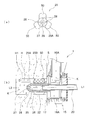
- FIG. 1 It is an external view containing the principal part cross section of the cutting waste discharging apparatus of embodiment of this invention.
- (A) is a front view of a discharge pipe fitted to a nozzle
- (b) is a cross-sectional view showing a state in which the nozzle and the discharge pipe are arranged in a bottomed lower hole.
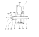
- It is sectional drawing which shows the state by which the discharge pipe of other embodiment was fitted by the nozzle.
- a cutting waste discharging apparatus 1 shown in FIG. 1 includes an L-type hose 10 and a nozzle 20.
- the L-type hose 10 is made of synthetic resin.
- the L-type hose 10 communicates with the suction passage 10 ⁇ / b> A and the suction part 15.
- the suction part 15 includes a cover part 16 and a suction part 17.
- the cover portion 16 is formed in a cylindrical shape from synthetic resin.
- the suction space 16A of the cover portion 16 communicates with the suction passage 10A.
- the suction portion 17 is formed in a cylindrical shape from synthetic rubber and is attached to the front surface of the cover portion 16.
- the suction portion 17 is brought into contact with the processing surface S of the work piece (concutt or the like). Make contact.
- the bottomed lower hole H is cut into the workpiece to form a predetermined hole for embedding an anchor bolt, for example.
- a dust collecting hose 40 is connected to the L-type hose 10 via a slide member 30.
- the slide member 30 is a hollow cylindrical member made of synthetic resin, and the L-type hose 10 and the dust collecting hose 40 are fitted into the slide member 30, respectively.
- a spring B is accommodated between the inner periphery of the slide member 30 and the L-shaped hose 10 and the dust collecting hose 40.
- the dust collecting hose 40 has excellent flexibility due to the bellows.
- the ring member 36 made of synthetic resin is fitted into the slide member 30.
- the ring-shaped member 36 is movable along the outer surface of the slide member 30 in the slide direction X of the slide member 30.
- the following slide operation handle 35 is fixed to the ring-shaped member 36.
- the pressing force against the outer peripheral surface of the slide member 30 is adjusted by the adjustment screw 37.
- the nozzle 20 is formed of a metal pipe.
- the rear end portion of the nozzle 20 is accommodated in the slide operation handle 35 with the rear end opening 21 being opened.
- the slide operation handle 35 is provided so as to protrude from the slide member 30 in a direction Y orthogonal to the slide direction X.
- the front end portion of the nozzle 20 is disposed in a state where the nozzle 20 enters the suction space 16A from the opening 16B of the cover portion 16 and penetrates the suction portion 15 and then protrudes from the front surface of the suction portion 17.
- the front end opening 22 of the nozzle 20 can be disposed in the bottomed lower hole H adjacent to the suction portion 17.
- the center line L1 of the nozzle 20 substantially coincides with the axis L2 of the bottomed lower hole H.
- a discharge pipe 25 made of synthetic resin having a tapered tip and a tapered shape is coaxially fitted to the front end of the nozzle 20.
- the discharge pipe 25 has an air introduction space 26 and a tip discharge port 27.
- the tip discharge port 27 communicates with the air introduction space 26.
- four side discharge ports 28 are circumferentially provided on the tapered surface 25 ⁇ / b> A of the discharge pipe 25 inclined toward the tip discharge port 27. Are formed at equal intervals.
- the side discharge port 28 communicates with the air introduction space 26, similarly to the tip discharge port 27.
- the brush 50 is fixed to the outer peripheral surface 25B of the discharge pipe 25 positioned in parallel with the axis L2 of the bottomed bottom hole H. As shown in the figure, the brush 50 is disposed so as to protrude radially from the outer peripheral surface 25 ⁇ / b> B toward the outside of the discharge pipe 25.
- the brush 50 is configured using a resinous fibrous member.
- the suction portion 17 is brought into contact with the processing surface S as shown in the figure. Thereafter, when the dust collector connected to the dust collection hose 40 is operated, the dust collector passes through the suction portion 17, the suction space 16 ⁇ / b> A, the suction passage 10 ⁇ / b> A, the L-type hose 10, and the dust collection hose 40. Is forcibly sucked. For this reason, the cutting waste K contained in the air is forcibly collected from the bottomed lower hole H by the dust collector, as indicated by the arrow in FIG.
- the cutting waste K floating in the bottomed bottom hole H is removed from the bottomed bottom hole H from the bottomed bottom hole H by the dust collector as described above, and the suction portion 17, the suction space 16 ⁇ / b> A, the suction passage 10 ⁇ / b> A, the L-type hose 10, Are collected sequentially.
- the air in the bottomed bottom hole H is forcibly sucked by the dust collector, and the air in the atmosphere is drawn into the bottomed bottom hole H by the nozzle 20 and the discharge pipe 25, thereby The inside air can be forcibly ventilated.
- the cutting waste K contained in the air is removed from the bottomed lower hole. It does not scatter directly into the atmosphere from H.
- the slide member 30 is made into the slide direction X, Comprising: The initial setting position P1 shown in FIG. It can reciprocate between.
- the sliding direction X is a direction parallel to the axis L2 (see FIG. 2B) of the bottomed bottom hole H.
- the operator When the operator wants to move the nozzle 20 forward toward the bottomed lower hole H, the operator grips the grip 35A of the slide operation handle 35 toward the direction (X1 direction in FIG. 3) where the bottomed lower hole H is located. Press and hold. At this time, the slide member 30 slides in the X1 direction along the dust collection hose 40 and the L-type hose 10 while receiving the spring pressure from the spring B, and reaches the position P2. Accordingly, the slide operation handle 35 provided so as to protrude from the slide member 30 and the front end portion of the nozzle 20 also slide in the X1 direction.
- the slide member 30 slides in the X2 direction along the L-type hose 10 and the dust collection hose 40 while receiving the above-described spring pressure, and reaches the position P1. Accordingly, the slide operation handle 35 and the front end of the nozzle 20 slide in the X2 direction.
- the slide member 30 and the spring B are an example of the slide mechanism of the present invention.
- the brush 50 can be brought into pressure contact with the inner wall H1, so that when the slide member 30 is reciprocated in the X1 direction and the X2 direction as described above, the inner wall H1.
- the brush 50 can be reciprocated along. Thereby, the brush 50 can scrape the cutting waste K adhering to the inner wall H1 into the bottomed lower hole H.
- the cutting waste K scraped into the bottomed bottom hole H is floated in the bottomed bottom hole H by the air ejected from the tip discharge port 27 and the side discharge port 28, and then is adsorbed by the dust collector by the dust collector. Collected from the bottomed bottom hole H through the suction space 16 ⁇ / b> A, the suction passage 10 ⁇ / b> A, the L-type hose 10 and the dust collection hose 40.
- the position of the front end opening 22 of the nozzle 20 is changed in a state where the slide member 30 is positioned at the initial setting position P ⁇ b> 1, thereby the front end opening 22.
- the separation distance X5 between the suction portion 15 (the suction portion 17) and the suction portion 15 can be adjusted. This procedure will be described below.
- the operator slides the slide member 30 toward the initial setting position P1, and arranges the slide member 30 at the initial setting position P1.
- the operator holds the grip 35A of the slide operation handle 35 and continues to push in the direction in which the bottomed lower hole H is located (X1 direction in the figure).
- the ring-shaped member 36 fixed to the slide operation handle 35 slides in the X1 direction along the outer surface of the slide member 30.
- the operator slides the ring-shaped member 36 to a predetermined position along the outer surface, and then presses the ring-shaped member 36 against the outer peripheral surface of the slide member 30 by tightening the adjustment screw 37.
- the movement of the ring-shaped member 36 is restricted, and the ring-shaped member 36 and the slide operation handle 35 are fixed at the predetermined position.
- the ring-shaped member 36 and the slide operation handle 35 are slid to predetermined positions in accordance with the processing depth D of the bottomed lower hole H (see FIG. 2B), as illustrated in FIG.
- the separation distance X5 is longer than the separation distance between the front end opening 22 and the suction portion 17 shown in FIG.
- the ring-shaped member 36 and the adjustment screw 37 are an example of a separation distance adjustment mechanism of the present invention.
- the above-described cutting waste discharging device 1 can be attached to the dust suction hammer drill 2.
- the front end portion 5 of the main body housing 4 with the drill chuck 3 protruding is fitted into a drill fitting hole integrated with the slide operation handle 35, and the cutting waste discharging device 1 is attached to the dust suction hammer drill 2.
- the rear end portion of the dust collection hose 40 was connected to an intake port projecting from the dust collection chamber 6 of the dust collection hammer drill 2 and communicated with the dust collection chamber 6.
- symbol 7 in a figure is a dust bag connected with a dust collection chamber.
- the air is continuously ejected from the tip discharge port 27 and the side discharge port 28 through the front end opening 22 of the nozzle 20 to the bottomed lower hole H whose internal pressure is equal to or lower than the atmospheric pressure, and at the same time, the suction passage
- the cutting waste K can be continuously discharged from the bottomed lower hole H through the L-type hose 10 and the dust collecting hose 40 communicating with 10A. Thereby, the operation
- the cutting waste K can continue to be discharged from the bottomed lower hole H through the L-shaped hose 10 and the dust collecting hose 40 communicating with the suction passage 10A, the cutting waste K in the bottomed lower hole H is transferred to the bottomed lower hole. Direct scattering from H can be prevented. Thereby, an unpleasant feeling is not given to the operator who discharges the cutting waste K.
- the air drawn into the nozzle 20 from the rear end opening 21 of the nozzle 20 is directed from the side discharge port 28 of the discharge pipe 25 fitted to the front end of the nozzle 20 toward the inner wall H1 of the bottomed lower hole H. Can be ejected. Thereby, the cutting waste K adhering to the inner wall H1 can be blown off from the inner wall H1.
- the brush 50 can be brought into pressure contact with the inner wall H1, and the cutting waste K adhering to the inner wall H1 can be scraped into the bottomed lower hole H. For this reason, the cutting waste K adhering to the inner wall H1 can be forcibly removed from the inner wall H1 by the brush 50.
- the slide member 30 is slid in the X1 direction or the X2 direction that is parallel to the axis L2 of the bottomed bottom hole H, so that the nozzle 20
- the front end can be advanced or retracted relative to the bottomed hole H.
- the position where air is ejected from the side discharge port 28 of the discharge pipe 25 fitted to the front end portion to the inner wall H1 and the brush 50 fixed to the outer peripheral surface 25B of the discharge pipe 25 are attached to the inner wall H1.
- the position to be pressed can be changed. Therefore, it is possible to blow away the cutting waste K adhering to the inner wall H ⁇ b> 1 without leakage by the air ejected from the side discharge port 28, or to forcibly remove the cutting waste K by the brush 50 without leakage.
- the present invention is not limited to the embodiment described above, and can be implemented by appropriately changing a part of the configuration without departing from the spirit of the invention.
- a discharge pipe 55 formed with the tip discharge port 27 and the side discharge port 28 without the brush 50 is provided at the front end of the nozzle 20. It may be fitted.
- the cutting waste K attached to the hole bottom and the inner wall H1 can be blown off and floated in the bottomed lower hole H.
- the four side discharge ports 28 are formed on the tapered surface 25A of the discharge pipe 25.
- the number of the side discharge ports 28 formed on the tapered surface 25A may be changed to an appropriate number.
- the cutting waste discharging device 1 may be attached to a hammer drill that does not have a dust absorbing function, while connecting the rear end portion of the dust collecting hose 40 to a dust collector.
- the opening area of the front end of the nozzle 20 is set as in the relationship between the rear end opening 21 and the front discharge port 27 and the relationship between the rear end opening 21 and the side discharge port 28. It is desirable that the opening area of the rear end opening 21 be set equal to or less than the opening area.
- the separation distance X5 is adjusted in a state where the slide member 30 is positioned at the initial setting position P1, but this is not limiting, and any arbitrary position different from the position P1 may be used.
- the separation distance X5 can also be adjusted with the slide member 30 positioned at the position.
- the cutting waste K is discharged from the bottomed lower hole H by the cutting waste discharging device 1
- the cutting waste can be discharged from the bottomed hole other than the lower hole.
- the cutting waste discharging device 1 is arranged in the vertical direction in order to discharge the cutting waste from the bottomed hole drilled in the wall, and is provided in the vertical direction so as to be drilled in the floor or the like. It can also be used when cutting waste is discharged from the bottom hole.
Landscapes
- Engineering & Computer Science (AREA)
- Mechanical Engineering (AREA)
- Auxiliary Devices For Machine Tools (AREA)
Abstract
【課題】切削屑の排出作業を容易かつ効率的に行うことができると共に、作業者に不快感を与えることを防ぐ切削屑排出装置及び切削屑排出装置を装着した電動工具を提供する。 【解決手段】有底孔(H)内の切削屑(K)を有底孔の外部に排出する切削屑排出装置(1)において、有底孔の開口部に密閉状態で接続される吸引部(15)を有し、吸引部を通じて有底孔から空気を強制的に吸引する吸引通路(10A)と、有底孔の軸線(L2)方向に設けられて吸引部を貫通して有底孔内に突出し、吸引通路によって空気を強制的に吸引することにより孔内圧力が大気圧以下となった有底孔に空気を噴出するノズル(20)と、を備え、ノズルによって有底孔に噴出させた空気により切削屑(K)を浮かせた後、切削屑(K)を吸引通路(10A)に吸引して有底孔(H)の外部に排出する。
Description
この発明は、例えば、所定の加工孔を形成するために穿設された有底下孔のように、切削屑が貯留している有底孔に対して用いられ、該切削屑を該有底孔の外部に排出する切削屑排出装置及び該切削屑排出装置を装着した電動工具に関する。
一般に、ドリルビットによってコンクリート等に下孔を切削し、該下孔にアンカーを挿入して固定させることが行われている。アンカーを下孔に挿入する前には、下孔を清掃して該下孔から切削屑を排出する必要がある。
特許文献1には、補助グリップの空洞部にエアブロワーを収納したハンマドリルが開示されている。下孔から切削屑を排出させる際には、ワイヤブラシによって下孔内に付着した切削屑を除去しつつ、エアブロワーによって下孔内にエアーを吹き付けることが行われる。
しかしながら、上述したように、ワイヤブラシ及びエアブロワーによって下孔から切削屑を排出させる場合には、二つの工具(ワイヤブラシ、エアブロワー)を用いて作業を行わなければならないため、工具の交換を含めた作業が面倒であった。
その上、エアーブロワーによって下孔内にエアーを吹き付ける場合には、該下孔内に均一に空気を吹き付けることができず、切削屑の排出効率が落ちることが懸念されていた。加えて、エアーブロワーによって下孔内にエアーを吹き付けると、切断屑が飛散することがあり、切削屑の排出を行う作業者に不快感を与えることがあった。
この発明は、このような状況に鑑み提案されたものであって、切削屑の排出作業を容易かつ効率的に行うことができると共に、作業者に不快感を与えることを防ぐ切削屑排出装置及び該切削屑排出装置を装着した電動工具を提供することを目的とする。
請求項1の発明は、有底孔内の切削屑を該有底孔の外部に排出する切削屑排出装置において、
前記有底孔の開口部に密閉状態で接続される吸引部を有し、該吸引部を通じて前記有底孔から空気を強制的に吸引する吸引通路と、
前記有底孔の軸線方向に設けられて前記吸引部を貫通して前記有底孔内に突出し、前記吸引通路によって前記空気を強制的に吸引することにより孔内圧力が大気圧以下となった前記有底孔に空気を噴出するノズルと、を備え、
前記ノズルによって前記有底孔に噴出させた前記空気により前記切削屑を浮かせた後、該切削屑を前記吸引通路に吸引して前記有底孔の外部に排出することを特徴とする。
前記有底孔の開口部に密閉状態で接続される吸引部を有し、該吸引部を通じて前記有底孔から空気を強制的に吸引する吸引通路と、
前記有底孔の軸線方向に設けられて前記吸引部を貫通して前記有底孔内に突出し、前記吸引通路によって前記空気を強制的に吸引することにより孔内圧力が大気圧以下となった前記有底孔に空気を噴出するノズルと、を備え、
前記ノズルによって前記有底孔に噴出させた前記空気により前記切削屑を浮かせた後、該切削屑を前記吸引通路に吸引して前記有底孔の外部に排出することを特徴とする。
請求項2の発明は、請求項1において、前記ノズルの側面に前記空気の噴出口が形成されていることを特徴とする。
請求項3の発明は、請求項1において、前記ノズルの側面から突き出して前記有底孔の内壁に接触するブラシを備えることを特徴とする。
請求項4の発明は、請求項1において、前記ノズルを前記有底孔の軸線方向に往復動可能なスライド機構を備えることを特徴とする。
請求項5の発明は、請求項1において、前記ノズルの空気噴出端部と前記吸引部との離間距離を調整可能な離間距離調整機構を備えることを特徴とする。
請求項10の発明に係る電動工具は、請求項1に記載の切削屑排出装置を装着したことを特徴とする。
特に、請求項1の発明に係る切断屑排出装置及び請求項10の発明に係る電動工具によれば、ノズルを通じ、孔内圧力が大気圧以下の有底孔内に連続して空気を噴出し続けると同時に、吸引通路を通じ、有底孔内の切削屑を該有底孔から排出し続けることができる。これにより、有底孔から切削屑を排出させる作業を容易かつ効率的に行うことができる。
さらに、上記のように、吸引通路を通じ、有底孔から切削屑を排出し続けることができれば、有底孔から切削屑が飛散することを防止できる。これにより、切削屑の排出を行う作業者に不快感を与えることがない。
特に、請求項2の発明によれば、ノズルに導入した空気を、該ノズルの側面に形成された空気の噴出口を通して有底孔の内壁に吹き付けることができる。これより、有底孔の内壁に付着する切削屑を吹き飛ばすことができる。
特に、請求項3の発明によれば、有底孔の内壁に、ノズルの側面から突き出したブラシを接触させることにより、内壁に付着した切削屑を強制的に除去することができる。
特に、請求項4の発明によれば、スライド機構によって、ノズルを有底孔の軸線方向に往復動させることにより、前記噴出口を通じて前記内壁に空気を吹き付ける位置や、前記ブラシが前記内壁に接触する位置をそれぞれ変化させることができる。これにより、噴出口からの空気によって、内壁に付着した切削屑を漏れなく吹き飛ばしたり、ブラシによって、該切削屑を漏れなく強制的に除去することが可能になる。
特に、請求項5の発明によれば、離間距離調整機構によって、ノズルの空気噴出端部と吸引部との離間距離を調整すると、加工深さがそれぞれ異なる複数の有底孔に対しても、各有底孔の開口部に吸引部を密閉状態で接続しつつ、空気噴出端部を各有底孔に到達させることができる。これにより、空気噴出端部を通じ、加工深さがそれぞれ異なる複数の有底孔に対しても、空気を噴出させることができる。
さらに、上記のように、吸引通路を通じ、有底孔から切削屑を排出し続けることができれば、有底孔から切削屑が飛散することを防止できる。これにより、切削屑の排出を行う作業者に不快感を与えることがない。
特に、請求項2の発明によれば、ノズルに導入した空気を、該ノズルの側面に形成された空気の噴出口を通して有底孔の内壁に吹き付けることができる。これより、有底孔の内壁に付着する切削屑を吹き飛ばすことができる。
特に、請求項3の発明によれば、有底孔の内壁に、ノズルの側面から突き出したブラシを接触させることにより、内壁に付着した切削屑を強制的に除去することができる。
特に、請求項4の発明によれば、スライド機構によって、ノズルを有底孔の軸線方向に往復動させることにより、前記噴出口を通じて前記内壁に空気を吹き付ける位置や、前記ブラシが前記内壁に接触する位置をそれぞれ変化させることができる。これにより、噴出口からの空気によって、内壁に付着した切削屑を漏れなく吹き飛ばしたり、ブラシによって、該切削屑を漏れなく強制的に除去することが可能になる。
特に、請求項5の発明によれば、離間距離調整機構によって、ノズルの空気噴出端部と吸引部との離間距離を調整すると、加工深さがそれぞれ異なる複数の有底孔に対しても、各有底孔の開口部に吸引部を密閉状態で接続しつつ、空気噴出端部を各有底孔に到達させることができる。これにより、空気噴出端部を通じ、加工深さがそれぞれ異なる複数の有底孔に対しても、空気を噴出させることができる。
<実施形態>
本発明の実施形態を、図1ないし図5を参照しつつ説明する。図1に示す切削屑排出装置1は、L型ホース10と、ノズル20とを備えている。
本発明の実施形態を、図1ないし図5を参照しつつ説明する。図1に示す切削屑排出装置1は、L型ホース10と、ノズル20とを備えている。
L型ホース10は、合成樹脂によって形成されている。L型ホース10は、吸引通路10A及び吸引部15と連通する。吸引部15は、カバー部16及び吸着部17を有する。カバー部16は、合成樹脂によって円筒状に形成されている。カバー部16の吸引空間16Aは、吸引通路10Aと連通する。吸着部17は、合成ゴムによって円筒状に形成され、カバー部16の前面に取り付けられている。後述するように、有底下孔Hから切削屑Kを収集する際には、図2の(b)図に示すように、吸着部17を、被切削物(コンクート等)の加工面Sに当接させる。有底下孔Hは、例えばアンカーボルト埋設用の所定の加工孔を形成するために、被切削物に切削されるものである。
また、L型ホース10には、スライド部材30を介し、集塵ホース40が連結されている。スライド部材30は、中空の合成樹脂製円筒部材であって、該スライド部材30には、L型ホース10及び集塵ホース40がそれぞれ嵌め込まれている。スライド部材30の内周と、L型ホース10及び集塵ホース40との間には、バネBが収容されている。集塵ホース40は、蛇腹を有することにより、屈曲性に優れている。有底下孔Hから切削屑Kを収集する際には、集塵ホース40の後端部に、切削屑Kを吸引する集塵機(図示せず。)を接続する。
スライド部材30には、合成樹脂製のリング状部材36が嵌め込まれている。リング状部材36は、スライド部材30の外側面に沿って該スライド部材30のスライド方向Xに移動可能である。リング状部材36には、下記のスライド操作ハンドル35が固定されている。リング状部材36については、調整ねじ37によって、スライド部材30の外周面に対する押圧力が調整される。
ノズル20は、金属製のパイプによって形成されている。ノズル20の後端部は、後端開口部21が開口した状態で、スライド操作ハンドル35に収容されている。スライド操作ハンドル35は、前記スライド方向Xと直交する方向Yへ、該スライド部材30から突出するように設けられている。
ノズル20の前端部は、カバー部16の開口部16Bから吸引空間16Aへ進入させて、吸引部15を貫通させた後に吸着部17の前面から突出させた状態で配置される。これにより、図2の(b)図に示すように、ノズル20の前端開口部22を、吸引部17に隣接する有底下孔H内に配置させることができる。このとき、ノズル20の中心線L1は、有底下孔Hの軸線L2とほぼ一致する。
さらに、図2の(b)図に示すように、ノズル20の前端部には、先端が先細りテーパ状となる合成樹脂製の吐出パイプ25が同軸で嵌着される。吐出パイプ25には、図2の(a)図、(b)図に示すように、空気導入空間26及び先端吐出口27が形成されている。先端吐出口27は、空気導入空間26と連通している。吐出パイプ25がノズル20の前端部に嵌着されることにより、ノズル20の前端開口部22は、空気導入空間26と連通する。
加えて、図2の(a)図、(b)図に例示するように、先端吐出口27に向けて傾斜する吐出パイプ25のテーパ面25Aには、4つの側部吐出口28が周方向に等間隔で形成されている。側部吐出口28は、先端吐出口27と同様に、空気導入空間26と連通する。
また、図2の(a)図、(b)図に示すように、有底下孔Hの軸線L2と平行に位置する吐出パイプ25の外周面25Bには、ブラシ50が固着される。ブラシ50は、図示するように、外周面25Bから該吐出パイプ25の外側に向けて放射状に突き出すように配置されている。ブラシ50は、樹脂製の繊維状部材を用いて構成されており、図2の(b)図に示すように、吐出パイプ25が有底下孔Hに送り込まれたときは、該有底下孔Hの内壁H1に、ブラシ50が圧接される。
次に、切削屑排出装置1により、有底下孔Hから切削屑Kを排出する方法を説明する。例えば、図示しないハンマドリルの切削ビットによって、被切削物に有底下孔Hを切削すると、有底下孔H内に切削屑K(図2の(b)図参照。)が残留する。
切削屑Kを有底下孔Hから排出するために、図示するように、上記の加工面Sに吸着部17を当接させる。その後、集塵ホース40に接続された集塵機を動作させると、該集塵機が、吸着部17、吸引空間16A、吸引通路10A、L型ホース10及び集塵ホース40を通じ、有底下孔H内の空気を、強制的に吸引する。このため、該空気と共に、図2の(b)図中の矢印の如く、空気に含まれる切削屑Kが、集塵機によって有底下孔Hから強制的に収集される。有底下孔H内の空気が強制的に吸引されることから、有底下孔Hの孔内圧力が大気圧以下の状態になり、合成ゴム製の吸着部17が加工面Sに吸着する。したがって、有底下孔Hの開口部と吸着部17との密閉性が高められる。
孔内圧力が大気圧以下の状態になると、ノズル20の後端開口部21(図1参照。)から該ノズル20内に大気中の空気が引き込まれる。ノズル20内に引き込まれた大気中の空気は、図2の(b)図の矢印に示す如く、前端開口部22を通じて空気導入空間26へ送られた後に、先端吐出口27から有底下孔Hの孔底に向けて噴出されると共に、側部吐出口28から有底下孔Hの内壁H1に向けて噴出される。これにより、大気中の空気が孔底や内壁H1に吹き付けられて、孔底や内壁H1に付着した切削屑Kは、吹き飛ばされて有底下孔H内に浮いた状態となる。なお、前端開口部22は、本発明のノズルの空気噴出端部の一例であり、側部吐出口28は、本発明の空気の噴出口の一例である。
有底下孔H内に浮いている切削屑Kは、上述したようにして、集塵機により、有底下孔Hから、吸着部17、吸引空間16A、吸引通路10A、L型ホース10及び集塵ホース40を順次通過して収集される。本実施形態では、集塵機によって、有底下孔H内の空気を強制的に吸引しつつ、ノズル20及び吐出パイプ25によって、有底下孔H内に大気中の空気を引き込むことにより、有底下孔H内の空気を強制的に換気することができる。さらに、有底下孔H内の空気は、吸引通路10A、L型ホース10、集塵ホース40やノズル20、吐出パイプ25を通じて換気されるため、該空気に含まれる切削屑Kが、有底下孔Hから直接大気中に飛散することがない。
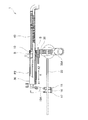
図1及び図3に示すように、切削屑排出装置1では、スライド部材30を、スライド方向Xであって、図1に示した初期設定位置P1と図3に示した任意の位置P2との間を往復動させることができる。スライド方向Xは、有底下孔Hの軸線L2(図2の(b)図参照。)と平行な方向である。
作業者は、ノズル20を有底下孔Hに向けて前進させたい場合には、スライド操作ハンドル35のグリップ35Aを握って有底下孔Hが位置する方向(図3中のX1方向)へ向けて押し続ける。このとき、スライド部材30は、バネBからバネ圧を受けながら、集塵ホース40及びL型ホース10に沿ってX1方向へスライドし、位置P2に到達する。これに伴って、スライド部材30から突出するように設けられたスライド操作ハンドル35やノズル20の前端部も、前記X1方向へスライドする。
一方、作業者は、ノズル20を有底下孔Hから後退させて、スライド部材30を任意の位置P2から初期設定位置P1に戻したい場合には、前記グリップ35Aを握って有底下孔Hから離れる方向(図3中のX2方向)へ向けて引き続ける。このとき、スライド部材30は、上記のバネ圧を受けながら、L型ホース10及び集塵ホース40に沿ってX2方向へスライドし、位置P1に到達する。これに伴って、スライド操作ハンドル35やノズル20の前端部が、前記X2方向へスライドする。なお、スライド部材30及びバネBは、本発明のスライド機構の一例である。
また、図2の(b)図に示すように、ブラシ50を内壁H1に圧接させることができるため、上述の如くスライド部材30をX1方向及びX2方向へ往復動させた場合には、内壁H1に沿ってブラシ50を往復動させることができる。これにより、ブラシ50が、内壁H1に付着した切削屑Kを有底下孔H内に掻き出すことができる。有底下孔H内に掻き出された切削屑Kは、先端吐出口27や側部吐出口28からそれぞれ噴出された空気によって該有底下孔H内に浮かされた後に、集塵機によって、吸着部17、吸引空間16A、吸引通路10A、L型ホース10及び集塵ホース40を通じて有底下孔Hから収集される。
図4に示すように、切削屑排出装置1では、例えば、スライド部材30を初期設定位置P1に位置させた状態で、ノズル20の前端開口部22の位置を変化させて、該前端開口部22と吸引部15(吸着部17)との離間距離X5を調整することができる。この手順を以下に説明する。
まず、作業者は、スライド部材30を初期設定位置P1に向けてスライドさせて、スライド部材30を該初期設定位置P1に配置する。次に、作業者は、調整ねじ37を緩めた後に、スライド操作ハンドル35のグリップ35Aを握って有底下孔Hが位置する方向(図中のX1方向)へ向けて押し続ける。これにより、スライド操作ハンドル35に固定されたリング状部材36は、スライド部材30の外側面に沿ってX1方向へスライドする。
続いて、作業者は、リング状部材36を前記外側面に沿って所定の位置までスライドさせた後に、調整ねじ37を締め付けることにより、リング状部材36をスライド部材30の外周面に押し付ける。これにより、リング状部材36の移動を規制して、該リング状部材36及びスライド操作ハンドル35を前記所定の位置に固定する。例えば、有底下孔Hの加工深さD(図2の(b)図参照。)に応じ、リング状部材36及びスライド操作ハンドル35を所定の位置にスライドさせると、図4に例示したように、図1とは異なり、離間距離X5が、図1に示した前端開口部22と吸着部17との間の離間距離に比べて長くなる。なお、リング状部材36及び調整ねじ37は、本発明の離間距離調整機構の一例である。
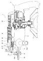
一方、図5に示すように、上述した切削屑排出装置1を、吸塵ハンマドリル2に取り付けることができる。本実施形態では、スライド操作ハンドル35と一体化されたドリル嵌着孔に、ドリルチャック3を突設させた本体ハウジング4の前端部5を嵌着させて、切削屑排出装置1を吸塵ハンマドリル2に支持させた。集塵ホース40の後端部は、吸塵ハンマドリル2の吸塵室6から突設した吸気口と接続し、該吸塵室6と連通させた。なお、図中の符号7は、吸塵室と繋がるダストバッグである。
<実施形態の効果>
本実施形態の切削屑排出装置1及び該切削屑排出装置1を取り付けた吸塵ハンマドリル2では、上述したように、ノズル20の後端開口部21から、孔内圧力が大気圧以下となった有底下孔Hに、大気中の空気を引き込んで、該有底下孔H内の切削屑Kを浮かせた後に吸引通路10Aと連通するL型ホース10や集塵ホース40を通過させて前記有底下孔Hから排出させる。
このため、ノズル20の前端開口部22を通じて先端吐出口27及び側部吐出口28から、孔内圧力が大気圧以下の有底下孔Hに連続して前記空気を噴出し続けると同時に、吸引通路10Aと連通するL型ホース10や集塵ホース40を通じて、有底下孔Hから切削屑Kを排出し続けることができる。
これにより、有底下孔Hから切削屑Kを排出させる作業を容易かつ効率的に行うことができる。
さらに、吸引通路10Aと連通するL型ホース10や集塵ホース40を通じて、有底下孔Hから切削屑Kを排出し続けることができれば、有底下孔H内の切削屑Kが、該有底下孔Hから直接飛散することを防止できる。これにより、切削屑Kの排出を行う作業者に不快感を与えることがない。
本実施形態の切削屑排出装置1及び該切削屑排出装置1を取り付けた吸塵ハンマドリル2では、上述したように、ノズル20の後端開口部21から、孔内圧力が大気圧以下となった有底下孔Hに、大気中の空気を引き込んで、該有底下孔H内の切削屑Kを浮かせた後に吸引通路10Aと連通するL型ホース10や集塵ホース40を通過させて前記有底下孔Hから排出させる。
このため、ノズル20の前端開口部22を通じて先端吐出口27及び側部吐出口28から、孔内圧力が大気圧以下の有底下孔Hに連続して前記空気を噴出し続けると同時に、吸引通路10Aと連通するL型ホース10や集塵ホース40を通じて、有底下孔Hから切削屑Kを排出し続けることができる。
これにより、有底下孔Hから切削屑Kを排出させる作業を容易かつ効率的に行うことができる。
さらに、吸引通路10Aと連通するL型ホース10や集塵ホース40を通じて、有底下孔Hから切削屑Kを排出し続けることができれば、有底下孔H内の切削屑Kが、該有底下孔Hから直接飛散することを防止できる。これにより、切削屑Kの排出を行う作業者に不快感を与えることがない。
また、ノズル20の後端開口部21からノズル20内に引き込んだ空気を、該ノズル20の前端部に嵌着された吐出パイプ25の側部吐出口28から有底下孔Hの内壁H1に向けて噴出することができる。これにより、内壁H1に付着した切削屑Kを、該内壁H1から吹き飛ばすことができる。
さらに、上述したように、ブラシ50を内壁H1に圧接させて、該内壁H1に付着した切削屑Kを有底下孔H内に掻き出すことができる。このため、ブラシ50によって、内壁H1に付着した切削屑Kを、該内壁H1から強制的に除去することができる。
加えて、上記のバネBからバネ圧を受けながら、スライド部材30を、有底下孔Hの軸線L2と平行な方向であるX1方向又はX2方向へスライドさせることにより、上述の如く、ノズル20の前端部を、有底下孔Hに対して前進又は後退させることができる。
これにより、前記前端部に嵌着された吐出パイプ25の側部吐出口28から内壁H1に空気を噴出する位置や、該吐出パイプ25の外周面25Bに固着されたブラシ50が前記内壁H1に圧接する位置を変化させることができる。
したがって、側部吐出口28から噴出する空気によって、内壁H1に付着した切削屑Kを漏れなく吹き飛ばしたり、ブラシ50によって、該切削屑Kを漏れなく強制的に除去することが可能になる。
これにより、前記前端部に嵌着された吐出パイプ25の側部吐出口28から内壁H1に空気を噴出する位置や、該吐出パイプ25の外周面25Bに固着されたブラシ50が前記内壁H1に圧接する位置を変化させることができる。
したがって、側部吐出口28から噴出する空気によって、内壁H1に付着した切削屑Kを漏れなく吹き飛ばしたり、ブラシ50によって、該切削屑Kを漏れなく強制的に除去することが可能になる。
さらに加えて、作業者が、スライド操作ハンドル35及びリング状部材36をスライド部材30の外側面に沿って任意の位置までスライドさせて、上記の離間距離X5を任意に調整することができれば、有底下孔Hの加工深さD(図2の(b)図参照。)がそれぞれ異なる複数の有底下孔に対しても、それぞれの有底下孔の開口部と吸着部17の密閉性を高めつつ、ノズル20の前端開口部22や吐出パイプ25をそれぞれの有底下孔に到達させることができる。
これにより、前端開口部22を通じて吐出パイプ25の先端吐出口27や側部吐出口28から、加工深さDが異なる複数の有底下孔の孔底や内壁H1に対しても、空気を噴出させることができる。
これにより、前端開口部22を通じて吐出パイプ25の先端吐出口27や側部吐出口28から、加工深さDが異なる複数の有底下孔の孔底や内壁H1に対しても、空気を噴出させることができる。
本発明は、上述した実施形態に限定されるものではなく、発明の趣旨を逸脱しない範囲内において構成の一部を適宜変更して実施することができる。例えば、上述した吐出パイプ25に代えて、図6に示すように、ブラシ50を有さずに、先端吐出口27や側部吐出口28を形成した吐出パイプ55を、ノズル20の前端部に嵌着させてもよい。これによって、上述した実施形態と同様に、孔底や内壁H1に付着した切削屑Kを吹き飛ばして有底下孔H内に浮いた状態にさせることができる。
また、上述した実施形態では、吐出パイプ25のテーパ面25Aに4つの側部吐出口28を形成したが、テーパ面25Aに形成する側部吐出口28の数を適宜の数に変更してもよい。さらに、集塵ホース40の後端部を集塵機に接続しつつ、上述した実施形態とは異なり、吸塵機能を有しないハンマドリルに、切削屑排出装置1を取り付けてもよい。
加えて、吐出パイプ25、55を用いずに、ノズル20の前端開口部22から有底下孔Hに空気を噴出して、該有底下孔H内に切削屑Kを浮かせてもよい。ただし、この場合には、上記の後端開口部21と先端吐出口27との関係や該後端開口部21と側部吐出口28との関係のように、ノズル20の前端の開口面積を、後端開口部21の開口面積と同等以下に設定することが望ましい。さらに加えて、上述した実施形態では、スライド部材30を初期設定位置P1に位置させた状態で、離間距離X5を調整することを例示したが、これに限らず、前記位置P1とは異なる任意の位置にスライド部材30を位置させた状態で、離間距離X5を調整することもできる。
上述した実施形態では、切削屑排出装置1によって、有底下孔Hから切削屑Kを排出させる例を説明したが、下孔以外の有底孔から切削屑を排出することもできる。さらに、切削屑排出装置1は、壁に穿設された有底孔から切削屑を排出するために水平方向に配置することに加え、鉛直方向に配置して、床等に穿設された有底孔から切削屑を排出する場合にも使用できる。
1・・切削屑排出装置、5・・本体ハウジングの前端部、10A・・吸引通路、15・・吸引部、20・・ノズル、22・・ノズルの前端開口部、28・・側部吐出口、30・・スライド部材、40・・集塵ホース、50・・ブラシ、B・・バネ、H・・有底下孔、H1・・有底下孔の内壁、K・・切削屑、L2・・有底下孔の軸線、X5・・先端開口部と吸引部との離間距離
Claims (10)
- 有底孔内の切削屑を該有底孔の外部に排出する切削屑排出装置において、
前記有底孔の開口部に密閉状態で接続される吸引部を有し、該吸引部を通じて前記有底孔から空気を強制的に吸引する吸引通路と、
前記有底孔の軸線方向に設けられて前記吸引部を貫通して前記有底孔内に突出し、前記吸引通路によって前記空気を強制的に吸引することにより孔内圧力が大気圧以下となった前記有底孔に空気を噴出するノズルと、を備え、
前記ノズルによって前記有底孔に噴出させた前記空気により前記切削屑を浮かせた後、該切削屑を前記吸引通路に吸引して前記有底孔の外部に排出することを特徴とする切削屑排出装置。 - 前記ノズルの側面に前記空気の噴出口が形成されていることを特徴とする請求項1に記載の切削屑排出装置。
- 前記ノズルの側面から突き出して前記有底孔の内壁に接触するブラシを備えることを特徴とする請求項1に記載の切削屑排出装置。
- 前記ノズルを前記有底孔の軸線方向に往復動可能なスライド機構を備えることを特徴とする請求項1に記載の切削屑排出装置。
- 前記ノズルの空気噴出端部と前記吸引部との離間距離を調整可能な離間距離調整機構を備えることを特徴とする請求項1に記載の切削屑排出装置。
- 前記噴出口は、前記側面の周方向に等間隔で複数形成されていることを特徴とする請求項2の記載の切削屑排出装置。
- 前記ブラシは、樹脂製の繊維状部材を用いて構成されたことを特徴とする請求項3に記載の切削屑排出装置。
- 前記スライド機構は、
前記有底孔の開口部に密閉状態で接続される吸引部を有して該吸引部を通じて前記有底孔から空気を強制的に吸引する吸引通路に連通して前記有底孔の軸線方向に設けられたホースに嵌め込まれて、該ホースに沿ってスライドするスライド部材と、
前記スライド部材の内周と前記ホースとの間に収容されたバネと、からなることを特徴とする請求項4に記載の切削屑排出装置。 - 前記離間距離調整機構は、
前記スライド部材に嵌め込まれて該スライド部材のスライド方向へ移動可能なリング状部材と、
前記スライド部材の外周面に前記リング状部材を押し付ける押圧力を調整する調整ねじと、からなることを特徴とする請求項5又は8に記載の切削屑排出装置。 - 請求項1に記載の切削屑排出装置を装着したことを特徴とする電動工具。
Applications Claiming Priority (2)
| Application Number | Priority Date | Filing Date | Title |
|---|---|---|---|
| JP2009123388A JP2010269406A (ja) | 2009-05-21 | 2009-05-21 | 切削屑排出装置及び電動工具 |
| JP2009-123388 | 2009-05-21 |
Publications (1)
| Publication Number | Publication Date |
|---|---|
| WO2010134429A1 true WO2010134429A1 (ja) | 2010-11-25 |
Family
ID=43126113
Family Applications (1)
| Application Number | Title | Priority Date | Filing Date |
|---|---|---|---|
| PCT/JP2010/057792 Ceased WO2010134429A1 (ja) | 2009-05-21 | 2010-05-07 | 切削屑排出装置及び電動工具 |
Country Status (2)
| Country | Link |
|---|---|
| JP (1) | JP2010269406A (ja) |
| WO (1) | WO2010134429A1 (ja) |
Citations (5)
| Publication number | Priority date | Publication date | Assignee | Title |
|---|---|---|---|---|
| JPS6222084U (ja) * | 1985-07-25 | 1987-02-10 | ||
| JPS6417388U (ja) * | 1987-07-17 | 1989-01-27 | ||
| JPH106156A (ja) * | 1996-06-17 | 1998-01-13 | Amada Co Ltd | 板材加工機のワークテーブル |
| JP2005153039A (ja) * | 2003-11-20 | 2005-06-16 | Honda Motor Co Ltd | 加工穴清掃装置 |
| JP2005329279A (ja) * | 2004-05-18 | 2005-12-02 | Honda Motor Co Ltd | 異物除去装置 |
-
2009
- 2009-05-21 JP JP2009123388A patent/JP2010269406A/ja active Pending
-
2010
- 2010-05-07 WO PCT/JP2010/057792 patent/WO2010134429A1/ja not_active Ceased
Patent Citations (5)
| Publication number | Priority date | Publication date | Assignee | Title |
|---|---|---|---|---|
| JPS6222084U (ja) * | 1985-07-25 | 1987-02-10 | ||
| JPS6417388U (ja) * | 1987-07-17 | 1989-01-27 | ||
| JPH106156A (ja) * | 1996-06-17 | 1998-01-13 | Amada Co Ltd | 板材加工機のワークテーブル |
| JP2005153039A (ja) * | 2003-11-20 | 2005-06-16 | Honda Motor Co Ltd | 加工穴清掃装置 |
| JP2005329279A (ja) * | 2004-05-18 | 2005-12-02 | Honda Motor Co Ltd | 異物除去装置 |
Also Published As
| Publication number | Publication date |
|---|---|
| JP2010269406A (ja) | 2010-12-02 |
Similar Documents
| Publication | Publication Date | Title |
|---|---|---|
| JP6562312B2 (ja) | 粉塵除去装置及び粉塵除去システム | |
| US7740086B2 (en) | Suction device for a pick power tool | |
| GB0305846D0 (en) | Dust extraction shrould for a power tool | |
| WO2012141702A1 (en) | System and method for capturing resultant dust from power tool operation | |
| US20070264092A1 (en) | Dust collector for drill | |
| RU2008143254A (ru) | Резательное или гравировальное устройство с инструментом, снабженным крыльчаткой для всасывания пыли | |
| CN210758494U (zh) | 一种新型手电钻 | |
| TW200728011A (en) | Laser beam processing machine | |
| JP2010172801A (ja) | ワークの清掃装置 | |
| RU2606137C2 (ru) | Пылеулавливающее устройство и ударный инструмент | |
| WO2010134429A1 (ja) | 切削屑排出装置及び電動工具 | |
| CN211437502U (zh) | 一种黄铜棒拉光机 | |
| CN105772808A (zh) | 一种吸气式自排屑麻花钻头 | |
| CN209648278U (zh) | 一种钻孔机防护罩 | |
| JP2009202285A (ja) | 切屑詰まり除去方法及び切屑詰まり除去装置 | |
| JP2011079061A (ja) | ダイ工具 | |
| EP4446040A1 (en) | Pneumatic drill system and foreign object debris collection drill attachment | |
| JP2000158286A (ja) | ワークの切削及び研削加工方法並びにこの切削及び研削加工方法に使用するオイルミスト除去装置 | |
| JP3001478U (ja) | 穴あけ装置 | |
| JPH07237193A (ja) | 穴あけ装置 | |
| CN220296466U (zh) | 一种用于加工叶导轮零件的钻床 | |
| JP2019014002A (ja) | 集塵装置 | |
| CN222327489U (zh) | 一种铝框打孔装置 | |
| CN217514286U (zh) | 一种防止排屑飞溅的冲击钻钻孔防护罩 | |
| KR200335874Y1 (ko) | 에어툴 |
Legal Events
| Date | Code | Title | Description |
|---|---|---|---|
| 121 | Ep: the epo has been informed by wipo that ep was designated in this application |
Ref document number: 10777663 Country of ref document: EP Kind code of ref document: A1 |
|
| NENP | Non-entry into the national phase |
Ref country code: DE |
|
| 122 | Ep: pct application non-entry in european phase |
Ref document number: 10777663 Country of ref document: EP Kind code of ref document: A1 |