WO2010131644A1 - ハイブリッド式作業機械の制御装置 - Google Patents
ハイブリッド式作業機械の制御装置 Download PDFInfo
- Publication number
- WO2010131644A1 WO2010131644A1 PCT/JP2010/057941 JP2010057941W WO2010131644A1 WO 2010131644 A1 WO2010131644 A1 WO 2010131644A1 JP 2010057941 W JP2010057941 W JP 2010057941W WO 2010131644 A1 WO2010131644 A1 WO 2010131644A1
- Authority
- WO
- WIPO (PCT)
- Prior art keywords
- power conversion
- conversion unit
- power
- generator
- control device
- Prior art date
- Legal status (The legal status is an assumption and is not a legal conclusion. Google has not performed a legal analysis and makes no representation as to the accuracy of the status listed.)
- Ceased
Links
Images


Classifications
-
- B—PERFORMING OPERATIONS; TRANSPORTING
- B60—VEHICLES IN GENERAL
- B60W—CONJOINT CONTROL OF VEHICLE SUB-UNITS OF DIFFERENT TYPE OR DIFFERENT FUNCTION; CONTROL SYSTEMS SPECIALLY ADAPTED FOR HYBRID VEHICLES; ROAD VEHICLE DRIVE CONTROL SYSTEMS FOR PURPOSES NOT RELATED TO THE CONTROL OF A PARTICULAR SUB-UNIT
- B60W20/00—Control systems specially adapted for hybrid vehicles
- B60W20/10—Controlling the power contribution of each of the prime movers to meet required power demand
- B60W20/13—Controlling the power contribution of each of the prime movers to meet required power demand in order to stay within battery power input or output limits; in order to prevent overcharging or battery depletion
-
- E—FIXED CONSTRUCTIONS
- E02—HYDRAULIC ENGINEERING; FOUNDATIONS; SOIL SHIFTING
- E02F—DREDGING; SOIL-SHIFTING
- E02F9/00—Component parts of dredgers or soil-shifting machines, not restricted to one of the kinds covered by groups E02F3/00 - E02F7/00
- E02F9/20—Drives; Control devices
- E02F9/2058—Electric or electro-mechanical or mechanical control devices of vehicle sub-units
- E02F9/2062—Control of propulsion units
- E02F9/2075—Control of propulsion units of the hybrid type
-
- B—PERFORMING OPERATIONS; TRANSPORTING
- B60—VEHICLES IN GENERAL
- B60W—CONJOINT CONTROL OF VEHICLE SUB-UNITS OF DIFFERENT TYPE OR DIFFERENT FUNCTION; CONTROL SYSTEMS SPECIALLY ADAPTED FOR HYBRID VEHICLES; ROAD VEHICLE DRIVE CONTROL SYSTEMS FOR PURPOSES NOT RELATED TO THE CONTROL OF A PARTICULAR SUB-UNIT
- B60W10/00—Conjoint control of vehicle sub-units of different type or different function
- B60W10/24—Conjoint control of vehicle sub-units of different type or different function including control of energy storage means
-
- H—ELECTRICITY
- H02—GENERATION; CONVERSION OR DISTRIBUTION OF ELECTRIC POWER
- H02J—ELECTRIC POWER NETWORKS; CIRCUIT ARRANGEMENTS OR SYSTEMS FOR SUPPLYING OR DISTRIBUTING ELECTRIC POWER; SYSTEMS FOR STORING ELECTRIC ENERGY
- H02J1/00—Circuit arrangements for DC mains or DC distribution networks
- H02J1/04—Current-controlled supply systems, e.g. constant-current supply systems
-
- H—ELECTRICITY
- H02—GENERATION; CONVERSION OR DISTRIBUTION OF ELECTRIC POWER
- H02M—APPARATUS FOR CONVERSION BETWEEN AC AND AC, BETWEEN AC AND DC, OR BETWEEN DC AND DC, AND FOR USE WITH MAINS OR SIMILAR POWER SUPPLY SYSTEMS; CONVERSION OF DC OR AC INPUT POWER INTO SURGE OUTPUT POWER; CONTROL OR REGULATION THEREOF
- H02M5/00—Conversion of AC power input into AC power output, e.g. for change of voltage, for change of frequency, for change of number of phases
- H02M5/02—Conversion of AC power input into AC power output, e.g. for change of voltage, for change of frequency, for change of number of phases without intermediate conversion into DC
- H02M5/04—Conversion of AC power input into AC power output, e.g. for change of voltage, for change of frequency, for change of number of phases without intermediate conversion into DC by static converters
- H02M5/22—Conversion of AC power input into AC power output, e.g. for change of voltage, for change of frequency, for change of number of phases without intermediate conversion into DC by static converters using discharge tubes with control electrode or semiconductor devices with control electrode
- H02M5/275—Conversion of AC power input into AC power output, e.g. for change of voltage, for change of frequency, for change of number of phases without intermediate conversion into DC by static converters using discharge tubes with control electrode or semiconductor devices with control electrode using devices of a triode or transistor type requiring continuous application of a control signal
- H02M5/293—Conversion of AC power input into AC power output, e.g. for change of voltage, for change of frequency, for change of number of phases without intermediate conversion into DC by static converters using discharge tubes with control electrode or semiconductor devices with control electrode using devices of a triode or transistor type requiring continuous application of a control signal using semiconductor devices only
Definitions
- the present invention relates to a control device for a work machine such as a construction machine, and more particularly to a control device for a hybrid work machine.
- the hybrid device has a power storage device as a main power source. In the hybrid device, this power storage device is charged by a generator motor.
- the inverter / converter controls the power storage device and the generator motor.
- the generator motor is driven by an engine, and the engine also drives a hydraulic pump for a hydraulic excavator device.
- the controller controls the operation of the hydraulic pump, the engine, and the generator motor based on the charge amount of the power storage device, the rotational speed of the generator motor, and the like.
- the object of the present invention is to provide a control device for a hybrid work machine that is downsized by increasing the degree of freedom of arrangement of components necessary for the hybrid type.
- One aspect of the hybrid work machine of one aspect of the present invention includes a three-phase AC generator connected to an engine.
- a first power converter is connected to the generator.
- a second power conversion unit is connected to the first power conversion unit, and the second power conversion unit controls the power of the swing electric motor in cooperation with the first power conversion unit.
- the first and second power converters can constitute an indirect matrix converter.
- a capacitor is disposed between the first power conversion unit and the second power conversion unit.
- a DC link is provided between the first power converter and the second power converter. The capacitor is connected to the DC link.
- the first power converter has a series circuit of an upper arm and a lower arm. A series circuit of the upper arm and the lower arm is provided in a number corresponding to the number of phases of the three-phase alternating current.
- each upper arm two diodes are connected in series, and the anodes of the two diodes are connected in series connection.
- two diodes are connected in series, and the cathodes of the two diodes are connected in series.
- a series circuit of these upper arm and lower arm is connected to both ends of the DC link.
- a first electrode of the switching element is connected to a connection portion between the anodes of the upper arms.
- the switching element also has a control electrode and a second electrode.
- a second electrode of the switching element is connected to a connection portion between the cathodes of the lower arms.
- the switching element causes a current to flow from the second electrode to the first electrode when a control signal is supplied to the control electrode.
- the switching element for example, IGBT, MOSFET, or GTO can be used.
- Each phase of the three-phase AC generator is connected to a connection portion between each upper arm and each lower arm.
- the first power conversion unit can be downsized.
- the drivers of these switching elements can also be reduced in size corresponding to the three switching elements.
- the hybrid work machine can also be reduced in size and the cost can be reduced. Further, since the number of switching elements used is reduced, switching loss is reduced, heat generation is reduced, and energy saving is achieved.
- the first power converter can limit the circuit to reduce the load on the generator. If comprised in this way, when the amount of electrical storage of a capacitor
- the amount of electricity stored in the battery can be controlled by the first power conversion unit according to the frequency of use of the swing electric motor.
- the amount of power stored in the capacitor can be reduced, and when the frequency of use of the swing electric motor is high, the amount of power stored in the capacitor can be increased.
- the amount of electricity stored in the battery is controlled according to the frequency of use, the battery is not charged more than necessary, and the efficiency can be improved.
- the first power conversion unit can control the power storage.
- the required work of any actuator other than the swing electric motor exceeds the supply work amount
- the load imposed on the generator for power storage is reduced, and the other actuator is used for that amount. Therefore, working efficiency can be improved.
- the present invention by reducing the number of switching elements used in the first power converter, the number of drive circuits for these switching elements is reduced, and the first power converter is downsized.
- the freedom degree of arrangement positioning of components required in order to set it as a hybrid type can be mentioned.
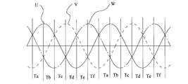
- FIG. 1 It is a block diagram of a hybrid type work machine control device of one embodiment of the present invention. It is a circuit diagram of the indirect matrix converter used in the control apparatus of FIG. It is a figure which shows the three-phase alternating current voltage supplied to the indirect matrix converter of FIG.
- a working machine for example, a hybrid construction machine has an engine 2 as shown in FIG.
- the engine 2 drives the hydraulic pump 4 and the generator 6.
- the hydraulic pump 4 functions as a drive source for the hydraulic actuator 8 of the hybrid construction machine.
- the hydraulic actuator 8 for example, an arm cylinder, a boom cylinder, a bucket cylinder, and a traveling hydraulic motor are used.
- the arm cylinder drives the arm
- the boom cylinder drives the boom
- the bucket cylinder drives the bucket.
- the arm, boom, and bucket are attached to the upper swing body of the hybrid construction machine.
- a traveling hydraulic motor drives a traveling body provided with the upper swing body so as to be able to swivel.
- a turning electric motor for example, a turning motor 10 is coupled to the upper turning body via a turning mechanism (not shown).
- the turning motor 10 is, for example, a three-phase electric motor. Electric power for rotating the turning motor 10 is generated by the generator 6.
- the generator 6 is, for example, a three-phase AC generator that generates three-phase AC power.
- the electric power generated by the generator 6 is converted in frequency and voltage by the indirect matrix converter 12 and supplied to the turning motor 10.
- the indirect matrix converter 12 includes a first power conversion unit 14 and a second power conversion unit 16 as shown in FIG.
- the first power conversion unit 14 has intermediate output terminals 18p and 18n. Between these intermediate output terminals 18p, 18n, three series circuits 20, 22, 24 are connected corresponding to the three phases of the three-phase AC generator 6. Each series circuit 20, 22, 24 includes an upper arm 26U, 28U, 30U and a lower arm 26D, 28D, 30D.
- the upper arm 26U has two diodes 32a and 32b. These two diodes 32a and 32b are connected in series with the anodes connected to each other.
- the lower arm 26D also has two diodes 34a and 34b. These two diodes 34a and 34b are connected in series with the cathodes connected to each other.
- the cathode of the diode 32a of the upper arm 26U is connected to the intermediate output terminal 18p
- the cathode of the diode 32b of the upper arm 26U and the anode of the diode 34a of the lower arm 26D are connected, and the anode of the diode 34b is connected to the intermediate output terminal 18n. It is connected to the. That is, the upper arm 26U and the lower arm 26D are connected in series between the intermediate output terminals 18p and 18n.
- a switching element for example, a first electrode of the IGBT 36, for example, an emitter, is connected to a connection part of the diodes 32a, 32b of the upper arm 26U.
- a second electrode of the IGBT 36 for example, a collector is connected to a connection portion between the diodes 34a and 34b of the lower arm 26D.
- the IGBT 36 has a control electrode, for example, a gate electrode. When a first level control signal, for example, an H level control signal is supplied to the gate electrode, the IGBT 36 conducts, and a current flows from the collector to the emitter.
- the upper arm 28U is constituted by diodes 38a and 38b
- the upper arm 30U is constituted by diodes 40a and 40b
- the lower arm 28D is configured by diodes 42a and 42b
- the lower arm 30D is configured by diodes 44a and 44b.
- the connection of the diodes 38a and 38b and the connection of the diodes 40a and 40b are the same as those of the diodes 32a and 32b.
- the connection of the diodes 42a and 42b and the connection of the diodes 44a and 44b are the same as the connection of the diodes 34a and 34b.
- the connection relationship between the upper arm 28U and the lower arm 28D and the connection relationship between the upper arm 30U and the lower arm 30D are the same as the connection relationship between the upper arm 26U and the lower arm 26D.
- the IGBT 46 is connected to the connection part of the diodes 38a and 38b and the connection part of the diodes 42a and 42b
- the IGBT 48 is connected to the connection part of the diodes 40a and 40b and the connection part of the diodes 44a and 44b.
- a power supply terminal 6 u of one phase u of the generator 6 is connected to a connection portion between the upper arm 26 U and the lower arm 26 D in the series circuit 20.
- a power terminal 6v of another phase v of the generator 6 is connected to a connection portion between the upper arm 28U and the lower arm 28D in the series circuit 22.
- a power supply terminal 6w of the other phase w of the generator 6 is connected to a connection portion between the upper arm 30U and the lower arm 30D in the series circuit 24.
- the second power conversion unit 16 has an intermediate DC input terminal 52p connected to the intermediate output terminal 18p via an intermediate DC power supply line 50p.
- the second power converter 16 also has an intermediate DC input terminal 52n connected to the intermediate DC output terminal 18n via an intermediate DC power supply line 50n.
- the second power conversion unit 18 also has AC output terminals 54u, 54v, 54w connected to each phase of the turning motor 10.
- a semiconductor switching element such as an IGBT 56 is connected between the intermediate DC input terminal 52p and the AC output terminal 54u.
- the collector of the IGBT 56 is connected to the intermediate DC input terminal 52p, and the emitter is connected to the AC output terminal 54u.
- a diode 58 is connected in antiparallel between the collector and emitter of the IGBT 56.
- an IGBT 60 is connected between the intermediate DC input terminal 52p and the AC output terminal 54v
- an IGBT 62 is connected between the intermediate DC input terminal 52p and the AC output terminal 54w.
- a diode 64 is connected in antiparallel between the collector and emitter of the IGBT 60.
- a diode 66 is connected in antiparallel between the collector and emitter of the GBT 62.
- IGBTs 68, 70, 72 are also connected between the AC output terminals 54u, 54v, 54w and the intermediate DC input terminal 52n.
- the collectors of the IGBTs 68, 70, 72 are connected to the AC output terminals 54u, 54v, 54w, respectively, and the emitters of the IGBTs 68, 70, 72 are connected to the intermediate DC input terminal 52n.
- Diodes 74, 76, and 78 are connected in antiparallel between the collectors and emitters of the IGBTs 68, 70, and 72.
- the second power conversion unit 18 is composed of six IGBTs and six diodes.
- a charge / discharge circuit 80 is provided between the intermediate DC power supply lines 82p and 82n.
- the charge / discharge circuit 80 has an IGBT 82.
- the collector of the IGBT 82 is connected to the intermediate DC power supply line 52p.
- the emitter of the IGBT 82 is connected to the intermediate DC power supply line 52n via a series circuit of a reactor 84 and a capacitor, for example, a capacitor 86.
- a capacitor 86 in addition to an electric double layer capacitor (EDLC), a hybrid capacitor such as a Li ion capacitor can be used.
- An IGBT 88 is connected in parallel with the series circuit of the reactor 84 and the capacitor 86.
- the collector is positioned on the reactor 84 side, and the emitter is positioned on the intermediate DC input terminal 52n side.
- a diode 90 is connected in antiparallel between the collector and emitter of the IGBT 82.
- a diode 92 is connected in antiparallel between the collector and emitter of the IGBT 88.
- the IGBTs 36, 46, 48, 52, 54, 56, 68, 70, 72, 82 and 88 may be MOSFETs (Metal Oxide Semiconductor Field Effect Transistors) or gate turn-off thyristors.
- Each IGBT of the first power conversion unit 14 and the second power conversion unit 16 is turned on by a PWM (Pulse Width Modulation) signal generated by the PWM generation unit 100 for the first power conversion and the second power conversion shown in FIG.
- the swivel motor 10 is supplied with AC power having a desired frequency and voltage.
- the PWM generator 100 generates a first power conversion PWM signal in accordance with the first power conversion command from the first power conversion command generator 102.
- the first power conversion command generation unit 102 generates a first power conversion command according to an instruction from the control unit of the work machine, for example, the control unit 104 of the hybrid construction machine.
- the second power conversion command generation unit 106 Based on the first power conversion command, the second power conversion command generation unit 106 generates a second power conversion command. This second power conversion command is supplied to the PWM generator 126, and the PWM generator 100 generates a PWM signal for second power conversion.
- the rectification in the first power conversion unit 14 is performed as follows. As shown in FIG. 3, the three-phase voltages U, V, and W generated at the power terminals 6u, 6v, and 6w of each phase of the generator 6 have a phase difference of 120 degrees, and the period Ta (the voltage V is negative). The line voltage Vuv is the largest during the period from when the voltage reaches the maximum value until the voltage U reaches the positive maximum value.
- a control signal is supplied so that the IGBTs 36 and 46 are turned on.
- a current flows from the power supply terminal 6u, the diode 34a, the IGBT 36, the diode 32a, and the intermediate output terminal 18p to the second power conversion unit 16.
- the current flowing from the second power converter 16 to the intermediate output terminal 18n is shunted to the diode 42b, the IGBT 46, the diode 38b, and the power supply terminal 6v.
- the line voltage Vuw is the largest during the period Tb (the period from the time when the voltage U becomes a positive maximum value to the time when the voltage W becomes a negative maximum value).
- Tb a control signal is supplied so that the IGBTs 36 and 48 are turned on.
- a current flows from the power supply terminal 6u, the diode 34a, the IGBT 36, the diode 32a, and the intermediate output terminal 18p to the second power conversion unit 16.
- the current that flows from the second power conversion unit 16 to the intermediate output terminal 18n flows to the diode 44b, the IGBT 48, the diode 40b, and the power supply terminal 6w.
- the line voltage Vvw is the largest.
- a control signal is supplied so that the IGBTs 46 and 48 are turned on. Thereby, a current flows from the power supply terminal 6v, the diode 42a, the IGBT 46, the diode 38a, and the intermediate output terminal 18p to the second power conversion unit 16.
- the current that flows from the second power conversion unit 16 to the intermediate output terminal 18n flows to the diode 44b, the IGBT 48, the diode 40b, and the power supply terminal 6w.
- the line voltage Vvu is the largest and the control signal is set so that the IGBTs 36 and 46 are turned on. Is supplied.
- the line voltage Vwu is the largest, and the control signal is turned on so that the IGBTs 36 and 48 are turned on. Supplied.
- a current flows from the power supply terminal 6w, the diode 44a, the IGBT 48, the diode 40a, and the intermediate output terminal 18p to the second power conversion unit 16.
- the current that flows from the second power conversion unit 16 to the intermediate output terminal 18n flows to the diode 34b, the IGBT 36, the diode 32b, and the power supply terminal 6u.
- the line voltage Vwv is the largest, and the control signal is turned on so that the IGBTs 46 and 48 are turned on.
- the current flows from the power supply terminal 6w, the diode 44a, the IGBT 48, the diode 40a, the intermediate output terminal 18p to the second power conversion unit 16, and from the second power conversion unit 16 to the intermediate output terminal 18n 42b, IGBT 46, diode 38b, and power supply terminal 6v.
- the first power conversion unit In a normal indirect matrix converter, the first power conversion unit is usually composed of 12 IGBTs each including a diode connected in antiparallel, and the configuration is complicated and large, and many Therefore, the switching loss is also large.
- the first power conversion unit 14 since the first power conversion unit 14 includes three IGBTs whose diodes are not connected in reverse parallel and a total of 12 diodes, the configuration of the first power conversion unit 14 is simple. 1 The power converter 14 can be downsized. In addition, since only three IGBTs are used in the first power conversion unit 14, the switching loss in the first power conversion unit 14 is also small.
- the IGBT 82 when the IGBTs 36, 46, and 48 are turned on and off, the IGBT 82 can be repeatedly turned on and off by a control signal from the control unit 104 of the hybrid construction machine. As a result, the charging circuit 80 operates as a chopper. By this chopper operation, the generator 6 generates electric power. Based on the generated electric power, the capacitor 86 can be charged while supplying electric power to the turning motor 10. This chopper operation is performed by repeating the following operation.
- the IGBT 82 By turning on the IGBT 82 for a predetermined time Ton, current flows from the intermediate output terminal 18p to the IGBT 82, the reactor 84, the capacitor 86, and the intermediate output terminal 18n, the magnetic energy is accumulated in the reactor 84, and the capacitor 86 is charged. .
- the IGBT 82 is turned off for a certain period Toff, and a current based on the magnetic energy of the reactor 84 is supplied to the reactor 84, the capacitor 86, and the diode 92, and the capacitor 86 is further charged.
- the amount of electricity stored in the capacitor 86 can be known.
- the voltage across the capacitor 86 is compared with a predetermined value, for example, a predetermined saturation reference value, by comparison means provided in the control unit 104 of the hybrid construction machine.
- the comparison means detects that the voltage across the capacitor 86 exceeds the saturation reference value
- the control unit 104 of the hybrid construction machine limits the circuit of the first power conversion unit 14.
- the IGBT 82 is turned off by a control signal from the control unit 104 of the hybrid construction machine. As a result, the capacitor 86 can be prevented from being saturated, and the load on the generator 6 can be reduced.
- the amount of charge to the capacitor 86 can be controlled as follows.
- the frequency of use of the swing motor 10 is, for example, the number of times that the swing motor 10 is driven per unit time or the total sum of currents that flow through the swing motor 10 per unit time.
- the frequency of use is measured by the control unit 104 of the hybrid construction machine, and the control unit 104 adjusts the on / off times Ton and Toff of the IGBT 82 in accordance with the measured value.
- Ton and Toff When the frequency is low, the lengths of the periods Ton and Toff are adjusted so that the amount of charge to the capacitor 86 is small.
- the control unit 104 adjusts the lengths of the periods Ton and Toff so that the amount of charge to the capacitor 86 increases.
- the charging circuit 80 operates as a chopper. This is because the potential between the intermediate output terminals 18p and 18n is not a perfect direct current but a cut waveform, and therefore it is difficult to control charging even when the IGBT 82 is continuously turned on. Since the rated voltage of the capacitor is 2.7 V to 3 V, if many capacitors are connected in series and the rated voltage of the capacitor is increased, the capacitor can be charged only by turning on the IGBT 82. However, since the internal resistances of many capacitors are connected in series, the loss due to the internal resistance increases and the cost required for many capacitors increases too much. For this reason, a certain number of capacitors are connected in series and then boosted and lowered by a chopper to charge and discharge a certain number of capacitors.
- One of the hydraulic actuators 8 such as an arm cylinder, a boom cylinder, a bucket cylinder, a traveling hydraulic motor, for example, a torque and a rotational speed of the traveling hydraulic motor, and a torque detector and a rotational speed detector provided in the traveling hydraulic motor.
- the control unit 104 calculates the amount of work supplied to the traveling hydraulic motor.
- the control unit 104 turns off the IGBT 82 and supplies the capacitor 86 to the capacitor 86. Suppress charging. As a result, the load on the generator 6 can be reduced, and the amount of work supplied to the traveling hydraulic motor can be turned by the reduced load.
- the control unit 104 compares the required work amount set corresponding to the arm cylinder and the calculated work amount, and the calculated work amount corresponds to the arm cylinder.
- the IGBT 82 can be turned off when the required work amount is larger than the required work amount.
- the control unit 104 compares the required work amount set for the boom cylinder with the calculated work amount, and the calculated work amount corresponds to the boom cylinder. When the required work amount is larger than the required work amount, the IGBT 82 can be turned off. The work amount is also calculated in the bucket cylinder, the control unit 104 compares the required work amount set for the bucket cylinder with the calculated work amount, and the calculated work amount is set for the bucket cylinder. The IGBT 82 can be turned off when it is larger than the required work amount.
Landscapes
- Engineering & Computer Science (AREA)
- Transportation (AREA)
- Power Engineering (AREA)
- Mechanical Engineering (AREA)
- Mining & Mineral Resources (AREA)
- Combustion & Propulsion (AREA)
- Chemical & Material Sciences (AREA)
- Civil Engineering (AREA)
- General Engineering & Computer Science (AREA)
- Structural Engineering (AREA)
- Automation & Control Theory (AREA)
- Operation Control Of Excavators (AREA)
- Inverter Devices (AREA)
- Control Of Eletrric Generators (AREA)
Abstract
【課題】 必要な部品の配置の自由度を上げて、ハイブリッド式作業機械を小型化する。 【解決手段】 発電機6に第1電力変換部14が接続され、第1電力変換部14に接続された第2電力変換部16が第1電力変換部14と協同して旋回モータ10の電力を制御する。第1電力変換部14は、2個のダイオードのアノード同士を直列接続した上側アーム26U、28U、30Uと、これらと直列に接続され、2個のダイオードのカソード同士を直列接続した下側アーム26D、28D、30Dとを有している。上側アーム26U、28U、30Uのアノード同士の接続部に、IGBT36、46、48のエミッタを接続し、下側アーム26D、28D、30Dのカソード同士の接続部にコレクタを接続してある。IGBT36、46、48は、ゲートに制御信号が供給されたときオンする。上側アーム26U、28U、30Uと下側アーム26D、28D、30Dの接続部に、発電機6の各相が接続されている。
Description
本発明は、例えば建設機械のような作業機械の制御装置に関し、特にハイブリッド式の作業機械の制御装置に関する。
建設機械、例えば油圧ショベルには、特許文献1に記載されているように、油圧ショベルの機器類に加えて、ハイブリッド機器を設けたものがある。ハイブリッド機器は、主電源となる蓄電装置を有している。ハイブリッド機器では、この蓄電装置を発電電動機が充電する。蓄電装置及び発電電動機をインバータ/コンバータが制御する。発電電動機は、エンジンによって駆動され、エンジンは、油圧ショベルの機器用の油圧ポンプも駆動する。蓄電装置の充電量や発電電動機の回転数等に基づいて、油圧ポンプ、エンジン、発電電動機の運転をコントローラが制御する。
しかし、このようなハイブリッド式の建設機械では、発電機、蓄電装置、コントローラ等の多数部品を油圧式の建設機械に追加収容しなければならない。しかも、これら部品は大型になりやすく、これら部品の配置に苦慮している。例えば、もしインバータ/コンバータにインダイレクトマトリクスコンバータを使用したなら、インダイレクトマトリクスコンバータ内のコンバータに相当する部分で、リバースダイオードをそれぞれ備えた12個ものIGBTを使用しなければならず、インダイレクトマトリクスコンバータ内のインバータに相当する部分にリバースダイオードをそれぞれ備えたIGBTを6個も使用しなければならない。しかも、これらIGBTそれぞれに対してドライブ回路を設けなければならず、これらドライブ回路は、互いに絶縁されていなければならない。そのため、これらドライブ回路を小型化することができなかった。
本発明は、ハイブリッド式とするために必要な部品の配置の自由度を上げて、小型化したハイブリッド式作業機械の制御装置を提供することを目的とする。
本発明の一態様のハイブリッド式作業機械の一態様は、エンジンに接続された三相交流の発電機を有している。この発電機に第1電力変換部が接続されている。第1電力変換部に第2電力変換部が接続され、第2電力変換部が第1電力変換部と協働して旋回電気モータの電力を制御する。例えば、第1及び第2電力変換部が、インダイレクトマトリクスコンバータを構成することもできる。第1電力変換部と第2電力変換部との間に蓄電器が配置されている。第1電力変換部と第2電力変換部との間に直流リンクが設けられている。前記蓄電器は、前記直流リンクに接続されている。前記第1電力変換部は、上側アームと下側アームとの直列回路を有している。上側アームと下側アームの直列回路は、前記三相交流の相数に対応した数だけ設けられている。各上側アームでは、2個のダイオードが直列接続されており、その直列接続では、2個のダイオードのアノード同士が接続されている。各下側アームでも、2個のダイオードが直列に接続されており、その2個のダイオードのカソード同士が直列に接続されている。これら上側アームと下側アームとの直列回路は、前記直流リンクの両端に接続されている。各前記上側アームのアノード同士の接続部に、スイッチング素子の第1の電極が接続されている。スイッチング素子は、制御電極と第2の電極も有している。各前記下側アームのカソード同士の接続部にスイッチング素子の第2の電極が接続されている。スイッチング素子は、その制御電極に制御信号が供給されたとき、第2の電極から第1の電極に電流を流す。スイッチング素子としては、例えばIGBTやMOSFETやGTOを使用することができる。前記各上側アームと前記各下側アームとの接続部に、三相交流発電機の各相が接続されている。
このように構成すると、第1電力変換部で使用するスイッチング素子は、わずか3個だけであり、第1電力変換部を小型化することができる。これらスイッチング素子のドライバも3個のスイッチング素子に対応した小型のものにできる。その結果、ハイブリッド式作業機械も小型化することができるし、コストを低減することもできる。また、使用されるスイッチング素子の数が減少しているので、スイッチング損失が減少し、発熱が減少し、省エネがはかられる。
前記蓄電器の蓄電量が所定値を超えたとき、前記第1電力変換部が回路を制限して、前記発電機の負荷を軽減することができる。このように構成すると、蓄電器の蓄電量が所定値を超えたときに、第1電力変換部を遮断して、充電を制限または止めることができる。これにより、蓄電器の蓄電量が飽和することを防止できる。
或いは、前記旋回電気モータの使用頻度に応じて、第1電力変換部により前記蓄電器の蓄電量を制御することもできる。このように構成すると、例えば旋回電気モータの使用頻度が少ないときには、蓄電器への蓄電量を少なくし、旋回電気モータの使用頻度が大きいときには、蓄電器への蓄電量を多くすることができる。このように使用頻度に応じて蓄電器での蓄電量を制御するので、必要以上に蓄電器に蓄電することが無く、効率を向上させることができる。
或いは、前記旋回電気モータ以外のいずれかのアクチュエータの必要仕事量が供給仕事量を超えたとき、前記第1電力変換部により蓄電を制御することもできる。このように構成すると、前記旋回電気モータ以外のいずれかのアクチュエータの必要仕事量が供給仕事量を超えたとき、蓄電用に発電機が負担していた負荷を軽減し、その分を他のアクチュエータに供給仕事量として回すことができるので、作業効率を向上させることができる。なお、蓄電を制限するときには、急激に蓄電量が変化することがないように徐々に充電量を変更して、操縦者に違和感を与えないようにすることが望ましい。
以上のように、本発明によれば、第1電力変換部に用いるスイッチング素子の数を減少させることによって、これらスイッチング素子に対するドライブ回路の数を減少させて、第1電力変換部を小型化し、これに伴いハイブリッド式とするために必要な部品の配置の自由度を挙げることができる。
本発明の1実施形態の作業機械、例えばハイブリッド建設機械は、図1に示すように、エンジン2を有している。エンジン2は、油圧ポンプ4及び発電機6を駆動する。油圧ポンプ4は、ハイブリッド建設機械の油圧アクチュエータ8の駆動源として機能する。油圧アクチュエータ8としては、例えばアームシリンダ、ブームシリンダ、バケットシリンダ及び走行油圧モータが使用される。
アームシリンダがアームを駆動し、ブームシリンダがブームを駆動し、バケットシリンダがバケットを駆動する。アーム、ブーム及びバケットは、ハイブリッド建設機械の上部旋回体に取り付けられている。この上部旋回体が旋回可能に設けられている走行体を走行油圧モータが駆動する。
上部旋回体を旋回させるために、上部旋回体に旋回機構(図示せず)を介して旋回電気モータ、例えば旋回モータ10が結合されている。旋回モータ10は、例えば三相電動機である。旋回モータ10を回転させるための電力が発電機6によって発電されている。発電機6は、例えば三相交流電力を発生する三相交流発電機である。
発電機6が発生した電力は、インダイレクトマトリクスコンバータ12において、周波数及び電圧が変換されて、旋回モータ10に供給される。
インダイレクトマトリクスコンバータ12は、図2に示すように、第1電力変換部14と、第2電力変換部16とを有している。
第1電力変換部14は、中間出力端子18p、18nを有し手いる。これら中間出力端子18p、18nの間に、三相交流発電機6の3つの相に対応して3つの直列回路20、22、24が接続されている。各直列回路20、22、24は、上側アーム26U、28U、30Uと下側アーム26D、28D、30Dとからなる。
上側アーム26Uは、2つのダイオード32a、32bを有し手いる。これら2つのダイオード32a、32bは、アノード同士が接続された状態で直列に接続されている。下側アーム26Dも、2つのダイオード34a、34bを有し手いる。これら2つのダイオード34a、34bは、カソード同士が接続された状態で直列に接続されている。上側アーム26Uのダイオード32aのカソードが中間出力端子18pに接続され、上側アーム26Uのダイオード32bのカソードと、下側アーム26Dのダイオード34aのアノードとが接続され、ダイオード34bのアノードが中間出力端子18nに接続されている。即ち、上側アーム26Uと下側アーム26Dとは、中間出力端子18p、18n間に直列に接続されている。
上側アーム26Uのダイオード32a、32bの接続部に、スイッチング素子、例えばIGBT36の第1電極、例えばエミッタが接続されている。下側アーム26Dのダイオード34a、34bの接続部に、IGBT36の第2電極、例えばコレクタが接続されている。IGBT36は、制御電極、例えばゲート電極を有している。ゲート電極に第1のレベル、例えばHレベルの制御信号が供給されたとき、IGBT36は、導通し、コレクタからエミッタへ電流を流す。
直列回路22、24でも、同様に上側アーム28Uは、ダイオード38a、38bによって構成され、上側アーム30Uは、ダイオード40a、40bによって構成されている。下側アーム28Dは、ダイオード42a、42bによって構成され、下側アーム30Dは、ダイオード44a、44bによって構成されている。ダイオード38a、38bの接続及びダイオード40a、40bの接続は、ダイオード32a、32bと同様である。ダイオード42a、42bの接続及びダイオード44a、44bの接続は、ダイオード34a、34bの接続と同様である。また、上側アーム28Uと下側アーム28Dとの接続関係、上側アーム30Uと下側アーム30Dとの接続関係は、上側アーム26Uと下側アーム26Dとの接続関係と同様である。
IGBT36と同様に、IGBT46が、ダイオード38a、38bの接続部とダイオード42a、42bの接続部とに接続され、IGBT48がダイオード40a、40bの接続部とダイオード44a、44bの接続部に接続されている。
直列回路20における上側アーム26Uと下側アーム26Dとの接続部に発電機6の1つの相uの電源端子6uが接続されている。直列回路22における上側アーム28Uと下側アーム28Dとの接続部に発電機6の別の相vの電源端子6vが接続されている。直列回路24における上側アーム30Uと下側アーム30Dとの接続部に、発電機6の他の相wの電源端子6wが接続されている。
第2電力変換部16は、中間出力端子18pに中間直流電源ライン50pを介して接続された中間直流入力端子52pを有している。また、第2電力変換部16は、中間直流出力端子18nに中間直流電源ライン50nを介して接続された中間直流入力端子52nも有している。さらに、第2電力変換部18は、旋回モータ10の各相に接続された交流出力端子54u、54v、54wも有している。
中間直流入力端子52pと交流出力端子54uとの間に半導体スイッチング素子、例えばIGBT56が接続されている。IGBT56のコレクタが中間直流入力端子52pに接続され、エミッタが交流出力端子54uに接続されている。IGBT56のコレクタ・エミッタ間に逆並列にダイオード58が接続されている。同様に、中間直流入力端子52pと交流出力端子54vの間にIGBT60が接続され、中間直流入力端子52pと交流出力端子54wの間にIGBT62が接続されている。IGBT60のコレクタ・エミッタ間に逆並列にダイオード64が接続されている。GBT62のコレクタ・エミッタ間に逆並列にダイオード66が接続されている。
同様に、交流出力端子54u、54v、54wと中間直流入力端子52nとの間にも、IGBT68、70、72が接続されている。IGBT68、70、72のコレクタが交流出力端子54u、54v、54wにそれぞれ接続され、IGBT68、70、72のエミッタが中間直流入力端子52nに接続されている。これらIGBT68、70、72のコレクタ・エミッタ間に逆並列にダイオード74、76、78が接続されている。
このように第2電力変換部18は、6個のIGBTと6個のダイオードとによって構成されている。
中間直流電源ライン82p、82n間に充放電回路80が設けられている。充放電回路80は、IGBT82を有している。IGBT82のコレクタが中間直流電源ライン52pに接続されている。IGBT82のエミッタは、リアクトル84と蓄電器、例えばキャパシタ86との直列回路を介して中間直流電源ライン52nに接続されている。キャパシタ86としては、電気二重層コンデンサ(EDLC)の他、ハイブリッド・キャパシタ、例えば、Liイオン・キャパシタなどを用いることができる。リアクトル84及びキャパシタ86の直列回路と並列に、IGBT88が接続されている。IGBT88では、コレクタがリアクトル84側に位置し、エミッタが中間直流入力端子52n側に位置している。IGBT82のコレクタ・エミッタ間には逆並列にダイオード90が接続されている。IGBT88のコレクタ・エミッタ間には逆並列にダイオード92が接続されている。
なお、IGBT36、46、48、52、54、56、68、70、72、82、88はMOSFET(Metal Oxide Semiconductor Field Effect Transistor)やゲートターンオフサイリスタであってもよい。
これら第1電力変換部14及び第2電力変換部16の各IGBTは、図1に示す第1電力変換及び第2電力変換用のPWM発生部100が発生するPWM(Pulse Width Modulation)信号によってオン、オフ制御され、旋回モータ10に所望の周波数及び電圧を持つ交流電力を供給する。
PWM発生部100は、第1電力変換指令生成部102からの第1電力変換指令に従って第1電力変換用のPWM信号を発生する。第1電力変換指令生成部102は、作業機械の制御部、例えばハイブリッド建設機械の制御部104からの指示に従って第1電力変換指令を生成する。第1電力変換指令に基づいて第2電力変換指令生成部106が第2電力変換指令を生成する。この第2電力変換指令が、PWM発生部126に供給され、PWM発生部100が第2電力変換用のPWM信号を発生する。
第1電力変換部14での整流は、次のように行われる。図3に示すように発電機6の各相の電源端子6u、6v、6wに発生する3相の電圧U、V、Wには120度の位相差があり、期間Ta(電圧Vが負の最大値となった時から、電圧Uが正の最大値になる時までの期間)では線間電圧Vuvが最も大きい。
期間Taに、IGBT36、46がオンするように制御信号が供給される。これによって、電源端子6u、ダイオード34a、IGBT36、ダイオード32a、中間出力端子18pから第2電力変換部16に電流が流れる。第2電力変換部16から、中間出力端子18nに流れた電流は、ダイオード42b、IGBT46、ダイオード38b、電源端子6vに分流する。
期間Tb(電圧Uが正の最大値になった時から、電圧Wが負の最大値になる時までの期間)には、線間電圧Vuwが最も大きい。この期間Tbでは、IGBT36、48がオンするように制御信号が供給される。これによって、電源端子6u、ダイオード34a、IGBT36、ダイオード32a、中間出力端子18pから第2電力変換部16に電流が流れる。第2電力変換部16から、中間出力端子18nに流れた電流は、ダイオード44b、IGBT48、ダイオード40b、電源端子6wに流れる。
期間Tc(電圧Wが負の最大値になった時から、電圧Vが正の最大値となる時までの期間)では、線間電圧Vvwが最も大きい。期間Tcでは、IGBT46、48がオンするように制御信号が供給される。これによって、電源端子6v、ダイオード42a、IGBT46、ダイオード38a、中間出力端子18pから第2電力変換部16に電流が流れる。第2電力変換部16から、中間出力端子18nに流れた電流は、ダイオード44b、IGBT48、ダイオード40b、電源端子6wに流れる。
期間Td(電圧Vが正の最大値となった時から、電圧Uが負の最大値になる時までの期間)は、線間電圧Vvuが最も大きく、IGBT36、46がオンするように制御信号が供給される。これによって、電源端子6v、ダイオード42a、IGBT46、ダイオード38a、中間出力端子18pから第2電力変換部16に電流が流れ、第2電力変換部16から、中間出力端子18nに流れた電流は、ダイオード34b、IGBT36、ダイオード32b、電源端子6uに流れる。
期間Te(電圧Uが負の最大値になった時から電圧Wが正の最大値になる時までの期間)では、線間電圧Vwuが最も大きく、IGBT36、48がオンするように制御信号が供給される。これによって、電源端子6w、ダイオード44a、IGBT48、ダイオード40a、中間出力端子18pから第2電力変換部16に電流が流れる。第2電力変換部16から、中間出力端子18nに流れた電流は、ダイオード34b、IGBT36、ダイオード32b、電源端子6uに流れる。
期間Tf(電圧Wが正の最大値になった時から電圧Vが負の最大値になる時までの期間)では、線間電圧Vwvが最も大きく、IGBT46、48がオンするように制御信号が供給され、電源端子6w、ダイオード44a、IGBT48、ダイオード40a、中間出力端子18pから第2電力変換部16に電流が流れ、第2電力変換部16から、中間出力端子18nに流れた電流は、ダイオード42b、IGBT46、ダイオード38b、電源端子6vに流れる。
無論、これら期間Ta乃至TfにおいてIGBT36、46、48をオフにすると、電流は流れない。従って、これら期間Ta乃至TfにおけるIGBT36、46、48がオンする期間をPWM発生部100からのPWM信号によって制御することによって、第2電力変換部16に供給される整流電流の値を調整することができる。
実際には、線間電圧の高低差を判断して、IGBT36、46、48のいずれを導通させるかを決定する。
通常のインダイレクトマトリクスコンバータにおいて、通常、第1電力変換部は、それぞれが逆並列に接続されたダイオードを備える12個のIGBTによって構成されており、その構成が複雑で大型である上に、多くのIGBTを使用しているので、スイッチング損失も大きい。しかし、第1電力変換部14は、ダイオードが逆並列接続されていない3つのIGBTと、合計12個のダイオードとによって構成されているので、第1電力変換部14の構成が簡単であり、第1電力変換部14の小型化が可能である。、しかも第1電力変換部14では、IGBTは3個しか使用していないので、第1電力変換部14でのスイッチング損失も小さい。
上記の説明では省略したが、IGBT36、46、48がオン、オフされているとき、ハイブリッド建設機械の制御部104からの制御信号によってIGBT82のオン、オフを繰り返すことができる。これによって充電回路80がチョッパ動作する。このチョッパ動作によって、発電機6が電力を発生する。この発生した電力に基づいて、旋回モータ10への電力の供給を行いつつ、キャパシタ86を充電することもできる。このチョッパ動作は次の動作を繰り返すことによって行われる。IGBT82を一定時間Tonの間、オンすることによって、中間出力端子18pからIGBT82、リアクトル84、キャパシタ86、中間出力端子18nに電流を流し、リアクトル84に磁気エネルギーを蓄積すると共に、キャパシタ86を充電する。次に、IGBT82を一定期間Toffの間オフとし、リアクトル84の磁気エネルギーに基づく電流を、リアクトル84、キャパシタ86、ダイオード92に流し、キャパシタ86をさらに充電する。
このキャパシタ86の両端間電圧を測定することによって、キャパシタ86への蓄電量を知ることができる。例えば、このキャパシタ86の両端間電圧を、ハイブリッド建設機械の制御部104に設けた比較手段によって、所定値、例えば予め定めた飽和基準値と比較する。ャパシタ86の両端間電圧が飽和基準値を超えていることが比較手段によって検出されたとき、ハイブリッド建設機械の制御部104が、第1電力変換部14の回路を制限する。例えばIGBT82をハイブリッド建設機械の制御部104からの制御信号によってオフとする。これによって、キャパシタ86が飽和することを防止できる上に、発電機6の負荷を軽減することができる。
キャパシタ86への充電量を次のようにして制御することができる。旋回モータ10の使用頻度を、例えば単位時間当たりに旋回モータ10が駆動された回数または単位時間当たりに旋回モータ10に流された電流の総和とする。この使用頻度の測定を、ハイブリッド建設機械の制御部104が行い、この測定値に応じて、制御部104がIGBT82のオン、オフの時間Ton、Toffを調整することによって、例えば旋回モータ10の使用頻度が少ないときには、キャパシタ86への充電量が少なくなるように、期間Ton、Toffの長さを調整する。旋回モータ10の使用頻度が大きいときには、キャパシタ86への充電量が多くなるように、制御部104が期間Ton、Toffの長さを調整する。
充電回路80はチョッパ動作する。これは、中間出力端子18p、18n間の電位が完全な直流ではなく、裁断波形であるので、IGBT82を連続的にオンしても充電を制御することが難しいからである。なお、キャパシタの定格電圧は2.7V~3Vであるので、多くのキャパシタを直列に接続してキャパシタの定格電圧を高くすると、IGBT82をオンするだけでキャパシタへの充電は可能である。しかし、多くのキャパシタの内部抵抗が直列に接続されるので、内部抵抗による損失が増すことや、多くのキャパシタに要する費用が増大しすぎる。そのため、ある程度の数のキャパシタを直列接続した上で、チョッパにより昇降圧をして、ある程度の数のキャパシタを充放電している.
アームシリンダ、ブームシリンダ、バケットシリンダ、走行油圧モータ等の油圧アクチュエータ8のいずれか、例えば走行油圧モータの例えばトルクと回転数とを、走行油圧モータに設けたトルク検出器と回転数検出器とによって検出する。検出されたトルクと回転数に基づいて、走行油圧モータに供給されている仕事量を制御部104が算出する。この算出された仕事量(供給されている仕事量)が、予め走行油圧モータ用に設定されている必要な仕事量よりも、少ないとき、制御部104がIGBT82をオフにして、キャパシタ86への充電を抑制する。これによって、発電機6の負荷を軽減して、その軽減された負荷の分だけ、走行油圧モータに供給仕事量を回すことができる。従って、作業効率を向上させることができる。なお、キャパシタ86への充電を抑制するために、IGBT82をオフにする必要がある。しかし、充電を抑制しようとしたときから直ちにIGBT82をオフにすると、急激にキャパシタ86の充電量が変化するので、ハイブリッド建設機械の操縦者に違和感を与える。そこで、IGBT82を徐々にオフにすることが望ましい。なお、アームシリンダにおいても仕事量を算出し、アームシリンダに対応して設定した必要仕事量と算出された仕事量とを制御部104が比較し、算出された仕事量が、アームシリンダに対応して設定した必要仕事量よりも大きいときには、IGBT82をオフにすることもできる。同様に、ブームシリンダにおいても仕事量を算出し、ブームシリンダに対応して設定した必要仕事量と算出された仕事量とを制御部104が比較し、算出された仕事量が、ブームシリンダに対応して設定した必要仕事量よりも大きいときには、IGBT82をオフにすることもできる。バケットシリンダにおいても仕事量を算出し、バケットシリンダに対応して設定した必要仕事量と算出された仕事量とを制御部104が比較し、算出された仕事量が、バケットシリンダに対応して設定した必要仕事量よりも大きいときには、IGBT82をオフにすることもできる。
Claims (4)
- エンジンに接続された三相交流の発電機と、
前記発電機に接続された第1電力変換部と、
前記第1電力変換部に接続され、旋回電気モータの電力を第1電力変換部と協同して制御する第2電力変換部と、
前記第1電力変換部と前記第2電力変換部との間に配置された蓄電器とを、
備えたハイブリッド式作業機械の制御装置において、
前記第1電力変換部と前記第2電力変換部との間に直流リンクを備え、前記蓄電器は、前記直流リンクに接続され、
前記第1電力変換部は、
2個のダイオードをそれらのアノード同士を直列接続した上側アームと、
前記上側アームと直列に接続され、2個のダイオードをそれらのカソード同士を直列接続した下側アームと、
前記上側アームのアノード同士の接続部に、第1の電極を接続し、前記下側アームのカソード同士の接続部に第2の電極を接続し、制御電極に制御信号が供給されたとき、第2の電極から第1の電極に電流を流すスイッチング素子とが、
前記三相交流発電機の各相ごとに、構成され、
各前記上側アームと各前記下側アームとの接続部に、三相交流発電機の各相が接続される
ハイブリッド式作業機械の制御装置。 - 請求項1記載のハイブリッド式作業機械の制御装置において、
前記蓄電器の蓄電量が所定値を超えたとき、前記第1電力変換部が回路を制限して、前記発電機の負荷を軽減したことを特徴とするハイブリッド式作業機械の制御装置。 - 請求項1記載のハイブリッド式作業機械の制御装置において、
前記旋回電気モータの使用頻度に応じて、第1電力変換部により前記蓄電器の蓄電量を制御することを特徴とするハイブリッド式作業機械の制御装置。 - 請求項1記載のハイブリッド式作業機械の制御装置において、
前記旋回電気モータ以外のいずれかのアクチュエータの必要仕事量が供給仕事量を超えたとき、前記第1電力変換部により蓄電を制御することを特徴とするハイブリッド式作業機械の制御装置。
Applications Claiming Priority (2)
| Application Number | Priority Date | Filing Date | Title |
|---|---|---|---|
| JP2009-115282 | 2009-05-12 | ||
| JP2009115282A JP2010268533A (ja) | 2009-05-12 | 2009-05-12 | ハイブリッド式作業機械の制御装置 |
Publications (1)
| Publication Number | Publication Date |
|---|---|
| WO2010131644A1 true WO2010131644A1 (ja) | 2010-11-18 |
Family
ID=43085016
Family Applications (1)
| Application Number | Title | Priority Date | Filing Date |
|---|---|---|---|
| PCT/JP2010/057941 Ceased WO2010131644A1 (ja) | 2009-05-12 | 2010-05-11 | ハイブリッド式作業機械の制御装置 |
Country Status (2)
| Country | Link |
|---|---|
| JP (1) | JP2010268533A (ja) |
| WO (1) | WO2010131644A1 (ja) |
Citations (7)
| Publication number | Priority date | Publication date | Assignee | Title |
|---|---|---|---|---|
| US20050099829A1 (en) * | 2003-06-20 | 2005-05-12 | Lixiang Wei | Dual bridge matrix converter |
| JP2006115635A (ja) * | 2004-10-15 | 2006-04-27 | Toyota Motor Corp | 電圧変換装置の制御装置及び制御方法 |
| JP2006352942A (ja) * | 2005-06-13 | 2006-12-28 | Sanken Electric Co Ltd | 電力変換装置 |
| WO2007123204A1 (ja) * | 2006-04-24 | 2007-11-01 | Daikin Industries, Ltd. | 直接形交流電力変換装置 |
| JP2008167619A (ja) * | 2007-01-04 | 2008-07-17 | Toyota Motor Corp | 電源装置およびそれを備える車両 |
| WO2008087689A1 (ja) * | 2007-01-16 | 2008-07-24 | Mitsubishi Electric Corporation | 電力変換装置 |
| WO2008123368A1 (ja) * | 2007-03-28 | 2008-10-16 | Komatsu Ltd. | ハイブリッド建設機械の制御方法およびハイブリッド建設機械 |
-
2009
- 2009-05-12 JP JP2009115282A patent/JP2010268533A/ja not_active Withdrawn
-
2010
- 2010-05-11 WO PCT/JP2010/057941 patent/WO2010131644A1/ja not_active Ceased
Patent Citations (7)
| Publication number | Priority date | Publication date | Assignee | Title |
|---|---|---|---|---|
| US20050099829A1 (en) * | 2003-06-20 | 2005-05-12 | Lixiang Wei | Dual bridge matrix converter |
| JP2006115635A (ja) * | 2004-10-15 | 2006-04-27 | Toyota Motor Corp | 電圧変換装置の制御装置及び制御方法 |
| JP2006352942A (ja) * | 2005-06-13 | 2006-12-28 | Sanken Electric Co Ltd | 電力変換装置 |
| WO2007123204A1 (ja) * | 2006-04-24 | 2007-11-01 | Daikin Industries, Ltd. | 直接形交流電力変換装置 |
| JP2008167619A (ja) * | 2007-01-04 | 2008-07-17 | Toyota Motor Corp | 電源装置およびそれを備える車両 |
| WO2008087689A1 (ja) * | 2007-01-16 | 2008-07-24 | Mitsubishi Electric Corporation | 電力変換装置 |
| WO2008123368A1 (ja) * | 2007-03-28 | 2008-10-16 | Komatsu Ltd. | ハイブリッド建設機械の制御方法およびハイブリッド建設機械 |
Non-Patent Citations (1)
| Title |
|---|
| J.W. KOLAR ET AL.: "Novel Three-Phase AC-DC-AC Sparse Matrix Converter", APPLIED POWER ELECTRONICS CONFERENCE AND EXPOSITION, 2002. APEC 2002, 2002, pages 777 - 791 * |
Also Published As
| Publication number | Publication date |
|---|---|
| JP2010268533A (ja) | 2010-11-25 |
Similar Documents
| Publication | Publication Date | Title |
|---|---|---|
| JP3910220B2 (ja) | 電気駆動システム | |
| US9083274B2 (en) | Power stage precharging and dynamic braking apparatus for multilevel inverter | |
| US10411588B2 (en) | Power converter with trench and planar transistors to improve efficiency | |
| JP5460835B1 (ja) | Dc/dc電圧変換装置およびその電圧変換制御方法 | |
| US8624538B2 (en) | Motor driving apparatus having function of dynamically switching converter operation mode of AC/DC converter | |
| US9735666B2 (en) | Power conversion device | |
| JP2013013220A (ja) | 電力変換装置 | |
| JP2634306B2 (ja) | インバータ装置の駆動回路 | |
| US20090001410A1 (en) | Driver Circuit and Electrical Power Conversion Device | |
| WO2011016328A1 (ja) | Dc-dcコンバータ回路 | |
| CN111224564B (zh) | 升降压驱动电路、方法、空调器和计算机可读存储介质 | |
| WO2012167691A1 (zh) | 逆变装置及应用其的太阳能光伏并网系统 | |
| AU2012364267B2 (en) | Converter controller with half bridge adaptive dead time circuit and method | |
| US20190273448A1 (en) | Method for operating a current converter and current converter operating according to said method | |
| JPWO2018225375A1 (ja) | 電力変換装置 | |
| CN109923779A (zh) | 混合整流器 | |
| JP5415387B2 (ja) | 電力変換装置 | |
| JPWO2020066031A1 (ja) | モータ駆動装置、送風機、圧縮機及び空気調和機 | |
| CN210405120U (zh) | 隔离总线逆变器系统 | |
| JP2004509591A (ja) | 能動的なクランピングスイッチを備える3レベル電力変換装置のための制御・調節方法、およびそのための装置 | |
| JP7106799B2 (ja) | 溶接電源装置 | |
| KR20130001298A (ko) | 하이브리드 건설 기계의 제어장치 | |
| CN108602150B (zh) | 用于有效地提供弧焊电源的系统和方法 | |
| WO2010131644A1 (ja) | ハイブリッド式作業機械の制御装置 | |
| WO2011013528A1 (ja) | Dc-dcコンバータ回路 |
Legal Events
| Date | Code | Title | Description |
|---|---|---|---|
| 121 | Ep: the epo has been informed by wipo that ep was designated in this application |
Ref document number: 10774901 Country of ref document: EP Kind code of ref document: A1 |
|
| NENP | Non-entry into the national phase |
Ref country code: DE |
|
| 122 | Ep: pct application non-entry in european phase |
Ref document number: 10774901 Country of ref document: EP Kind code of ref document: A1 |