WO2010122798A1 - 水分発生用反応炉 - Google Patents
水分発生用反応炉 Download PDFInfo
- Publication number
- WO2010122798A1 WO2010122798A1 PCT/JP2010/002914 JP2010002914W WO2010122798A1 WO 2010122798 A1 WO2010122798 A1 WO 2010122798A1 JP 2010002914 W JP2010002914 W JP 2010002914W WO 2010122798 A1 WO2010122798 A1 WO 2010122798A1
- Authority
- WO
- WIPO (PCT)
- Prior art keywords
- barrier layer
- reactor
- platinum catalyst
- main body
- catalytic activity
- Prior art date
- Legal status (The legal status is an assumption and is not a legal conclusion. Google has not performed a legal analysis and makes no representation as to the accuracy of the status listed.)
- Ceased
Links
Images

Classifications
-
- C—CHEMISTRY; METALLURGY
- C01—INORGANIC CHEMISTRY
- C01B—NON-METALLIC ELEMENTS; COMPOUNDS THEREOF; METALLOIDS OR COMPOUNDS THEREOF NOT COVERED BY SUBCLASS C01C
- C01B5/00—Water
-
- B—PERFORMING OPERATIONS; TRANSPORTING
- B01—PHYSICAL OR CHEMICAL PROCESSES OR APPARATUS IN GENERAL
- B01J—CHEMICAL OR PHYSICAL PROCESSES, e.g. CATALYSIS OR COLLOID CHEMISTRY; THEIR RELEVANT APPARATUS
- B01J12/00—Chemical processes in general for reacting gaseous media with gaseous media; Apparatus specially adapted therefor
-
- B—PERFORMING OPERATIONS; TRANSPORTING
- B01—PHYSICAL OR CHEMICAL PROCESSES OR APPARATUS IN GENERAL
- B01J—CHEMICAL OR PHYSICAL PROCESSES, e.g. CATALYSIS OR COLLOID CHEMISTRY; THEIR RELEVANT APPARATUS
- B01J12/00—Chemical processes in general for reacting gaseous media with gaseous media; Apparatus specially adapted therefor
- B01J12/007—Chemical processes in general for reacting gaseous media with gaseous media; Apparatus specially adapted therefor in the presence of catalytically active bodies, e.g. porous plates
-
- B—PERFORMING OPERATIONS; TRANSPORTING
- B01—PHYSICAL OR CHEMICAL PROCESSES OR APPARATUS IN GENERAL
- B01J—CHEMICAL OR PHYSICAL PROCESSES, e.g. CATALYSIS OR COLLOID CHEMISTRY; THEIR RELEVANT APPARATUS
- B01J19/00—Chemical, physical or physico-chemical processes in general; Their relevant apparatus
- B01J19/24—Stationary reactors without moving elements inside
-
- B—PERFORMING OPERATIONS; TRANSPORTING
- B01—PHYSICAL OR CHEMICAL PROCESSES OR APPARATUS IN GENERAL
- B01J—CHEMICAL OR PHYSICAL PROCESSES, e.g. CATALYSIS OR COLLOID CHEMISTRY; THEIR RELEVANT APPARATUS
- B01J23/00—Catalysts comprising metals or metal oxides or hydroxides, not provided for in group B01J21/00
- B01J23/38—Catalysts comprising metals or metal oxides or hydroxides, not provided for in group B01J21/00 of noble metals
- B01J23/54—Catalysts comprising metals or metal oxides or hydroxides, not provided for in group B01J21/00 of noble metals combined with metals, oxides or hydroxides provided for in groups B01J23/02 - B01J23/36
- B01J23/56—Platinum group metals
- B01J23/63—Platinum group metals with rare earths or actinides
-
- B—PERFORMING OPERATIONS; TRANSPORTING
- B01—PHYSICAL OR CHEMICAL PROCESSES OR APPARATUS IN GENERAL
- B01J—CHEMICAL OR PHYSICAL PROCESSES, e.g. CATALYSIS OR COLLOID CHEMISTRY; THEIR RELEVANT APPARATUS
- B01J37/00—Processes, in general, for preparing catalysts; Processes, in general, for activation of catalysts
- B01J37/02—Impregnation, coating or precipitation
- B01J37/024—Multiple impregnation or coating
- B01J37/0244—Coatings comprising several layers
-
- B—PERFORMING OPERATIONS; TRANSPORTING
- B01—PHYSICAL OR CHEMICAL PROCESSES OR APPARATUS IN GENERAL
- B01J—CHEMICAL OR PHYSICAL PROCESSES, e.g. CATALYSIS OR COLLOID CHEMISTRY; THEIR RELEVANT APPARATUS
- B01J23/00—Catalysts comprising metals or metal oxides or hydroxides, not provided for in group B01J21/00
- B01J23/38—Catalysts comprising metals or metal oxides or hydroxides, not provided for in group B01J21/00 of noble metals
- B01J23/40—Catalysts comprising metals or metal oxides or hydroxides, not provided for in group B01J21/00 of noble metals of the platinum group metals
- B01J23/42—Platinum
-
- B—PERFORMING OPERATIONS; TRANSPORTING
- B01—PHYSICAL OR CHEMICAL PROCESSES OR APPARATUS IN GENERAL
- B01J—CHEMICAL OR PHYSICAL PROCESSES, e.g. CATALYSIS OR COLLOID CHEMISTRY; THEIR RELEVANT APPARATUS
- B01J35/00—Catalysts, in general, characterised by their form or physical properties
- B01J35/40—Catalysts, in general, characterised by their form or physical properties characterised by dimensions, e.g. grain size
-
- B—PERFORMING OPERATIONS; TRANSPORTING
- B01—PHYSICAL OR CHEMICAL PROCESSES OR APPARATUS IN GENERAL
- B01J—CHEMICAL OR PHYSICAL PROCESSES, e.g. CATALYSIS OR COLLOID CHEMISTRY; THEIR RELEVANT APPARATUS
- B01J37/00—Processes, in general, for preparing catalysts; Processes, in general, for activation of catalysts
- B01J37/02—Impregnation, coating or precipitation
- B01J37/0215—Coating
- B01J37/0225—Coating of metal substrates
Definitions
- hydrogen gas and oxygen gas are supplied into a reaction furnace having a platinum catalyst layer and subjected to a catalytic reaction, so that an ignition point (500 to 500 ° C.) of hydrogen gas and oxygen gas is obtained without burning (about 2000 ° C.).
- the present invention relates to a water generation reactor for generating high-purity water at a catalytic reaction temperature lower than 580 ° C. (400 ° C. or lower).
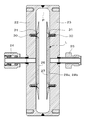
- a reactor main body having a reaction internal space P is formed by combining and welding the furnace main body members 22 and 23 in a facing manner.
- the reactor main body is provided with a raw material gas inlet 24, a moisture gas outlet 25, an inlet-side reflector 26, an outlet-side reflector 27, and the like, and the inner wall surface of the furnace body member 23 on the side facing the raw material gas inlet 24.
- a barrier layer 28a is formed between the stainless steel base material of the reaction furnace and the platinum catalyst layer 28b, and the barrier layer prevents impurities in the base material from diffusing into the platinum catalyst layer 28b. Prevents layer degradation.
- the thickness of the barrier layer 28a is about 0.1 ⁇ m to 5 ⁇ m.
- the barrier layer 28a made of TiN is formed by an ion plating method.
- the platinum catalyst layer 28b has a thickness of 1 nm to 0.5 mm, and is formed by, for example, a vacuum deposition method.
- a PVD method such as an ion sputtering method or a vacuum vapor deposition method, a chemical vapor deposition method (CVD method), a hot press method, a thermal spray method, or the like can be used as a method for forming the barrier layer 28a.
- the platinum catalyst layer 28b is formed by ion plating, ion sputtering, chemical vapor deposition, hot pressing, or the like, and the barrier layer 28a is made of a conductive material such as TiN. For some materials, plating is also used.
- the conventional barrier layer made of TiN or the like has a problem that the adhesion force (peeling strength) of the platinum catalyst layer to the barrier layer is lowered when it is used for a long time.
- Such a decrease in adhesion with time is caused by the fact that oxygen (O 2 radicals) activated by the catalytic reaction passes through the platinum catalyst layer and gradually oxidizes the vicinity of the interface between the barrier catalyst layer and the platinum catalyst layer. This is considered to reduce the adhesion between the layer and the platinum catalyst layer.
- the platinum catalyst layer may be caused by an unexpected impact on the water generation reactor due to an unintended drop during maintenance. There is a risk of partial peeling.
- the peeled platinum becomes a contamination, which has a serious adverse effect on the quality of the manufactured semiconductor.
- the peeled platinum has a small heat capacity, and the temperature rises due to the reaction heat generated by the catalytic reaction of hydrogen gas and oxygen gas, resulting in an ignition source. Safety issues also arise.
- the main object of the present invention is to provide a reactor for generating moisture that can maintain a high adhesion of the platinum catalyst layer to the barrier layer for a long period of time.
- the present inventors have found that the platinum catalyst layer can maintain a high adhesive force with the barrier layer for a long period of time by forming the barrier layer with Y 2 O 3 .
- the present invention provides a reactor main body provided with a gas inlet and a moisture outlet, a Y 2 O 3 barrier layer formed on at least a part of the inner wall surface of the reactor main body, And a platinum catalyst layer formed on at least a part of the Y 2 O 3 barrier layer.
- the film thickness of the Y 2 O 3 layer is preferably 50 nm to 5 ⁇ m, and more preferably 100 to 300 nm.
- the reactor main body is preferably made of a material that does not have catalytic activity with respect to hydrogen and oxygen.
- the reactor for generating moisture further includes at least one reflector in the reactor main body, and the reflector is formed of a material that does not have catalytic activity for hydrogen and oxygen.
- the reflector is fixed to the reactor main body by a fixing screw via a spacer so as to block at least one of the gas inlet and the moisture outlet through a predetermined interval, and the spacer and the fixing screw Is preferably made of a material having no catalytic activity with respect to hydrogen and oxygen.
- a material having no catalytic activity for hydrogen and oxygen for a member having a surface in contact with gas in the reaction furnace, such as a reaction furnace main body member or a reflector.
- the material having no catalytic activity is preferably an iron-chromium-aluminum alloy, an aluminum alloy, or a copper alloy.
- a portion of the reactor main body other than the portion provided with the platinum catalyst layer in the internal space is covered with a barrier layer made of a material having no catalytic activity with respect to hydrogen and oxygen.
- the moisture generating reactor further includes at least one reflector in the reactor body, and the reflector is covered with a barrier layer made of a material having no catalytic activity with respect to hydrogen and oxygen. Preferably it is.
- the reflector is fixed to the reactor main body by a fixing screw via a spacer so as to block at least one of the gas inlet and the moisture outlet through a predetermined interval, and the spacer and the fixed It is preferable that the screw is covered with a barrier layer made of a material having no catalytic activity with respect to hydrogen and oxygen.
- the barrier layer made of a material having no catalytic activity is at least one selected from the group consisting of TiN, TiC, TiCN, TiAlN, Al 2 O 3 , Cr 2 O 3 , SiO 2 , CrN, and Y 2 O 3. It is preferably formed of a seed material.
- the Y 2 O 3 barrier layer is formed on the inner wall surface of the reactor main body, and the platinum catalyst layer is formed on the Y 2 O 3 barrier layer, whereby the Y 2 O 3 barrier of the platinum catalyst layer is formed. It is possible to suppress a decrease in adhesion force to the layer over time.
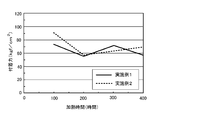
- the results of testing the adhesion of the Y 2 O 3 barrier layer of the platinum catalyst layer for Examples 1 and 2 of the present invention is a graph showing.
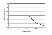
- the results of testing the adhesion of the Y 2 O 3 barrier layer of the platinum catalyst layer for Examples 3 and 4 of the present invention is a graph showing. It is a graph which shows the result of having tested the adhesive force to the TiN barrier layer of a platinum catalyst layer about a comparative example. It is a longitudinal cross-sectional view which shows one form of the conventional reactor for moisture generation.
- FIG. 4 an embodiment of a water generation reactor according to the present invention will be described with reference to FIGS. Except for the point that the barrier layer 28a is Y 2 O 3 , the structure of the water generating reactor is the same as that of the conventional one, so FIG. 4 is referred to.
- a Y 2 O 3 barrier layer is formed on the inner wall surface of the furnace body member 23 on the outlet side, and a platinum catalyst layer 28b is formed on the Y 2 O 3 barrier layer.
- This Y 2 O 3 barrier layer is a barrier layer that prevents impurities in the base material of the furnace body member 23 from diffusing into the platinum catalyst layer 28b.
- the moisture generation reaction is actively performed in the vicinity of the inlet of the source gas inlet 24, the temperature of the inlet side connection fittings and the like may be excessively increased. It is desirable not to form a platinum catalyst layer in the range of at least about 10 mm radius from the center of 24, preferably in the range of about 15 to 25 m radius.
- the base material of the reactor main body for example, stainless steel such as SUS316L, nickel alloy steel, or nickel steel can be used.
- the platinum catalyst layer in the furnace is formed especially when the reaction furnace body is made of a material that can exert a catalytic activity on O 2 and H 2 such as stainless steel, nickel alloy steel, and nickel steel. It is desirable to form a non-catalytic barrier layer having no catalytic activity against oxygen and hydrogen as a barrier layer for hindering catalytic activity by the base material.
- a barrier layer material include TiN, TiC 3, TiCN 3 , TiAlN, Al 2 O 3 , Cr 2 O 3 , SiO 2 , and CrN, but Y 2 O 3 may also be used. Two or more of these materials may be used.
- the base material of the reflector 26, 27, O 2 and when relative H 2 is a material that can have a catalytic activity action, oxygen and forming a non-catalytic barrier layer having no catalytic activity for hydrogen It is desirable to film.
- this barrier layer is used as a barrier layer for hindering catalytic activity due to the base material
- this barrier layer is used as a barrier layer for preventing impurities in the base material from diffusing into the platinum catalyst layer 28b.
- the reflectors 26 and 27 can be arranged facing each other in the reaction furnace. Although the reflectors 26 and 27 are formed in a disk shape in the illustrated example, the reflectors 26 and 27 may be capable of increasing the efficiency of diffusing the mixed gas by collision with the mixed gas flowing into the internal space P of the reactor. The form is not limited.
- the reflector 26 on the inlet side is fixed to the furnace main body member 22 by a fixing screw 30 via a spacer 31 so as to block the source gas inlet 24 through a certain gap from the furnace main body member 22 on the inlet side.
- the outlet-side reflector 26 is also fixed to the furnace main body member 23 by a fixing screw 30 via a spacer 31 so as to block the source gas inlet 24 through a certain gap from the outlet-side furnace main body member 22. .
- the reflector can be fixed not only by screwing but also by other fixing means such as welding.
- the example provided with a pair of reflector was shown in the example of illustration, only one reflector may be sufficient and the reflector 27 of the exit side preferably may be provided in that case.
- the mixed gas G injected toward the reflector 26 through the source gas inlet 24 is diffused in the internal space P after colliding with the reflector 26, and the diffused mixed gas G extends over the entire surface of the platinum catalyst layer 28b.
- the so-called catalyst is activated by collision contact substantially uniformly, and moisture gas is generated by the reaction between H 2 and O 2 .
- the moisture gas formed in the internal space P is led out to the moisture gas outlet 25 through the gap L between the outlet-side reflector 27 and the outlet-side furnace body member 23.
- a catalytic activity is exerted on O 2 gas and H 2 gas such as stainless steel, nickel alloy steel and nickel steel.
- O 2 gas and H 2 gas such as stainless steel, nickel alloy steel and nickel steel.
- a material that does not have a catalytic activity for O 2 gas or H 2 gas for example, an iron-chromium-aluminum alloy, an aluminum alloy, or a copper alloy may be used.
- the base material of the reactor main body members 22 and 23 of the reaction furnace is formed of a material having no catalytic activity as described above, in a portion other than the portion provided with the Y 2 O 3 barrier layer 28a in the internal space, It is desirable to perform an appropriate surface treatment for preventing the release of internal gas and internal metal composition material to the outer surface of these non-catalytic materials.
- a non-catalytic barrier layer excellent in corrosion resistance, reduction resistance and oxidation resistance can be formed.
- TiN, TiC, TiCN, TiAlN, Al 2 O 3 , Cr 2 O 3 , SiO 2 , or CrN can be used, but Y 2 O 3 may also be used. Two or more of these materials may be used.
- the barrier layer is used as a barrier layer for preventing impurities in the base material from diffusing into the platinum catalyst layer 28b.
- the reflectors 26 and 27 are preferably subjected to the same surface treatment as described above.
- the Y 2 O 3 barrier layer can be suitably formed by a sol-gel method.
- a sol-gel method for example, an organic solvent solution of yttrium alkoxide is spin-coated or dip-coated on a base material of a furnace body formed of stainless steel or the like.
- the film can be formed by applying by spray coating or the like, drying the coating film, and baking in an oxygen atmosphere at 500 to 600 ° C. for 1 to 5 hours.
- the barrier layer of TiN, TiC, TiCN, TiAlN, Al 2 O 3 , Cr 2 O 3 , SiO 2 , or CrN is formed by a PVD method such as an ion plating method, a sputtering method, a vacuum evaporation method, or a chemical vapor deposition method ( A thickness of 0.1 to 5 ⁇ m can be formed using a CVD method, a hot press method, a thermal spraying method, or the like.
- a film having a film thickness of about 50 nm can be obtained by one application and baking, so that a desired film thickness can be obtained as necessary.
- the application and baking are repeated a plurality of times until it reaches 100 (for example, 100 nm, 300 nm).
- the thickness of the Y 2 O 3 barrier layer is preferably set to 300 nm or less.
- yttrium and thinner film thickness for an expensive material Y 2 O 3 barrier layer reduce costs, reduce the barrier properties when the film thickness of the Y 2 O 3 barrier layer is too thin Since the film thickness of the Y 2 O 3 barrier layer is usually 100 nm or more, the function can be sufficiently exhibited if it is 50 nm or more.
- the Y 2 O 3 barrier layer is preferably formed by a sol-gel method from the viewpoint of cost reduction of manufacturing equipment, but is not limited thereto, and is not limited to a thermal spray method, a PVD method, a vacuum evaporation method, a sputtering method, an ion plate.
- a film can also be formed by a coating method or the like.
- a dry method such as a thermal spraying method
- the film thickness of the Y 2 O 3 barrier layer can be increased without repeating the same steps as in the wet method, but the material cost can be increased even in the case of the dry method.
- the thickness of the Y 2 O 3 barrier layer is 5 ⁇ m or less.
- a platinum catalyst layer is formed on the Y 2 O 3 barrier layer.
- the platinum catalyst layer can be formed by a vacuum deposition method, an ion plating method, a sputtering method, a chemical vapor deposition method, a hot press method, or the like.
- the film thickness of the platinum catalyst layer is preferably 0.1 ⁇ m to 3 ⁇ m (100 nm to 3000 nm). That is, if it is too thin, the function as a catalyst and the function as the protective film cannot be sufficiently achieved. Therefore, the thickness is preferably 0.1 ⁇ m (100 nm) or more. On the other hand, if the platinum catalyst layer is considered to have a function as a catalyst and a function as a protective film of the barrier layer as will be described later, it is preferable to increase the film thickness.
- the thickness is preferably 3 ⁇ m (3000 nm) or less, and more preferably 0.5 ⁇ m (500 nm) or less.
- Example 1 The adhesion of the platinum catalyst layer to the Y 2 O 3 barrier layer was tested by the following procedure.
- Example 1 First, a circular substrate (diameter 35 mm ⁇ thickness 3 mm) made of SUS316L was prepared.
- Y 2 O 3 coating material (YYK01LBY-03: brown liquid) manufactured by Kojundo Chemical Laboratory Co., Ltd. was sprayed onto the substrate with a spray nozzle, dried, and then oxidized with an O 2 / N 2 ratio of 20%.
- Heat treatment (baking) was performed in an atmosphere at 500 ° C. for 1 hour.
- a Y 2 O 3 film having a thickness of about 50 nm was formed by one application and heat treatment, and a Y 2 O 3 barrier layer having a thickness of about 100 nm was formed by repeating the application and heat treatment twice. .
- a platinum catalyst layer was formed as follows on the Y 2 O 3 barrier layer using an ion plating apparatus (AAIF-T12100SB type manufactured by Shinko Seiki Co., Ltd.).
- a platinum catalyst layer was formed by ion plating.
- Ar bombardment was performed at an Ar flow rate of 260 sccm, a substrate bias of 1500 V, and a processing time of 10 minutes.
- a platinum catalyst layer having a substrate bias of ⁇ 500 V, an ionization electrode of 50 V, a film formation rate of 0.025 ⁇ m / min, an EB voltage of 9 kV, and a film thickness of 0.23 ⁇ m (230 nm) was formed.
- the adhesion test was performed on the examples formed as described above.
- the test apparatus used was an adhesion tester (coating film adhesion tester, Type 0610 manufactured by Co-Tech Co., Ltd.).
- the dolly attached to the test apparatus was adhered to the platinum catalyst layer using a predetermined epoxy resin adhesive.
- the sample to which the dolly was bonded was heated in an air atmosphere at 500 ° C. for 400 hours to accelerate the environment, and the peel strength was measured with an adhesion tester every 50 hours.
- Example 2 In the same manner as in Example 1, a Y 2 O 3 barrier layer having a film thickness of 0.3 ⁇ m (300 nm) was formed on the substrate, and a film having a film thickness of 0.23 ⁇ m (230 nm) was formed on the Y 2 O 3 barrier layer. A platinum catalyst layer was formed, and an adhesion test using an adhesion tester was performed under the same conditions as in Example 1.
- Example 3 A sample similar to Example 1 was prepared except that the thickness of the platinum catalyst layer was 0.28 ⁇ m (280 nm).
- the dolly attached to the test apparatus was adhered to the platinum catalyst layer using a predetermined epoxy resin adhesive.
- the sample to which the dolly was bonded was heated in an air atmosphere at 500 ° C. for 1000 hours to accelerate the environment, and the peel strength was measured with an adhesion tester every 50 hours.
- Example 4 The same sample as in Example 3 was used.
- the dolly attached to the test apparatus was adhered to the platinum catalyst layer using a predetermined epoxy resin adhesive.
- the sample to which the dolly was adhered was heated in an air atmosphere at 550 ° C. for 1000 hours to accelerate the environment, and the peel strength was measured with an adhesion tester every 50 hours.
- Comparative Example A TiN film was used as a barrier layer in place of the Y 2 O 3 film, and a platinum catalyst layer was formed on the TiN barrier layer.
- the TiN barrier layer was formed using a cathode arc type ion plating apparatus, and the film thickness was 3 ⁇ m.
- a platinum catalyst layer of 0.3 ⁇ m (300 nm) was formed on the formed TiN barrier layer by an ion plating apparatus (AAIF-T12100SB type manufactured by Shinko Seiki Co., Ltd.).
- the peel strength test using the adhesion tester was performed while accelerating the environment by heating in an air atmosphere at 500 ° C.
- FIGS. 1 and 2 show the test results of Examples 1 and 2
- FIG. 2 shows the test results of Examples 3 and 4
- FIG. 3 shows the test results of the comparative example.
- the adhesive force is extremely reduced after 200 hours, but in Examples 1 and 2, the adhesive force is hardly reduced even after 400 hours. In addition, it can be seen that in Examples 3 and 4, the adhesive force hardly decreases even after 1000 hours.
- Example 1 and Example 2 were compared, even if the film thickness of the Y 2 O 3 barrier layer was changed, no influence on the adhesive force was observed. However, if Example 1 and Example 3 are compared, Example 3 in which the platinum catalyst layer is thicker than Example 1 maintains a higher adhesive force. It can be seen that a thicker film maintains higher adhesion. This is probably because the thicker platinum catalyst layer is less likely to oxidize the vicinity of the interface between the Y 2 O 3 barrier layer and the platinum catalyst layer. That is, the platinum catalyst layer is considered to function as a protective film that protects the Y 2 O 3 barrier layer from oxidation.
- the Y 2 O 3 barrier layer has a film thickness (0.3 ⁇ m, 0.1 ⁇ m) which is 1/10 or less of the TiN barrier layer (3 ⁇ m), It was found to maintain a higher adhesion than the TiN barrier layer. This is presumably because the Y 2 O 3 barrier layer is a stable material having a large standardized Gibbs energy and superior oxidation resistance than the TiN barrier layer. Therefore, by controlling the film thickness of the Y 2 O 3 barrier layer, even if yttrium that is more expensive than titanium is used, it has a better adhesion performance at a cost equivalent to or lower than that of the TiN barrier layer. A 2 O 3 barrier layer can be formed.
Landscapes
- Chemical & Material Sciences (AREA)
- Organic Chemistry (AREA)
- Chemical Kinetics & Catalysis (AREA)
- Engineering & Computer Science (AREA)
- Materials Engineering (AREA)
- Inorganic Chemistry (AREA)
- Catalysts (AREA)
Abstract
Description
白金触媒層のY2O3バリア層に対する付着力について、以下の手順にて試験した。
まず、SUS316L製の円形基板(直径35mm×厚さ3mm)を用意した。 株式会社高純度化学研究所製Y2O3コート材料(YYK01LBY-03:褐色液体)を、スプレーノズルよって基板上に吹き付けて塗布し、乾燥させた後、O2/N2比20%の酸化雰囲気中で500℃×1時間の加熱処理(焼成)を施した。一度の塗布及び加熱処理により、約50nmの膜厚のY2O3膜が成膜され、塗布及び加熱処理を2回繰り返すことにより、約100nmの膜厚のY2O3バリア層を形成した。
実施例1と同様にして、膜厚0.3μm(300nm)のY2O3バリア層を基板上に成膜し、該Y2O3バリア層の上に膜厚0.23μm(230nm)の白金触媒層を成膜し、実施例1と同条件でアドヒージョンテスターによる付着力試験を行った。
白金触媒層の膜厚を0.28μm(280nm)とした以外は実施例1と同様の試料を作成した。
実施例3と同じ試料を用いた。試験装置に付属のドリーを、所定のエポキシ樹脂系接着剤を用いて、白金触媒層に接着させた。ドリーを接着した試料を、550℃の空気雰囲気で1000時間加熱して環境加速を行いつつ、50時間毎にアドヒージョンテスターによる剥離強度測定を行った。
Y2O3膜に代えてTiN膜をバリア層とし、TiNバリア層上に白金触媒層を形成した。TiNバリア層は、カソードアーク方式イオンプレーティング装置を用いて成膜し、膜厚を3μmとした。成膜したTiNバリア層の上に、イオンプレーティング装置(神港精機株式会社製AAIF―T12100SB型)により、0.3μm(300nm)の白金触媒層を成膜した。実施例1~3と同様に、500℃の空気雰囲気で加熱して環境加速を行いつつ、前記アドヒージョンテスターによる剥離強度試験を行った。
24 原料ガス入口
25 水分ガス出口
26 入口側反射体
27 出口側反射体
28a バリア層
28b 白金触媒層
30 固定ネジ
31 スペーサー
Claims (11)
- ガス入口及び水分出口が設けられた反応炉本体と、前記反応炉本体の内壁面の少なくとも一部に成膜されたY2O3バリア層と、該Y2O3バリア層上の少なくとも一部に成膜された白金触媒層と、を有することを特徴とする水分発生用反応炉。
- 前記Y2O3バリア層の膜厚が50nm~5μmであることを特徴とする請求項1に記載の水分発生用反応炉。
- 前記反応炉本体が、水素及び酸素に対して触媒活性を有しない材料によって形成されていることを特徴とする請求項1に記載の水分発生用反応炉。
- 少なくとも1枚の反射体を前記反応炉本体内に更に備え、該反射体が水素及び酸素に対して触媒活性を有しない材料によって形成されていることを特徴とする請求項1に記載の水分発生用反応炉。
- 前記反射体は、前記ガス入口及び前記水分出口の少なくとも一方を所定間隔を介して遮るように、前記反応炉本体にスペーサーを介して固定ネジによって固定されており、前記スペーサー及び前記固定ネジが水素及び酸素に対して触媒活性を有しない材質によって形成されていることを特徴とする請求項4に記載の水分発生用反応炉。
- 反応炉本体部材や反射体のような反応炉内のガスに接する面を有する部材を、水素及び酸素に対して触媒活性を有しない材質を使用するようにした請求項1に記載の水分発生用反応炉。
- 前記触媒活性を有しない材料が、鉄-クロム-アルミ合金、アルミ合金、又は銅合金であることを特徴とする請求項3~6の何れかに記載の水分発生用反応炉。
- 前記反応炉本体の、内部空間内の前記白金触媒層を設けた部分以外の部位が、水素及び酸素に対して触媒活性を有しない材質からなるバリア層によって被覆されていることを特徴とする請求項1に記載の水分発生用反応炉。
- 少なくとも1枚の反射体を前記反応炉本体内に更に備え、該反射体が、水素及び酸素に対して触媒活性を有しない材料からなるバリア層によって被覆されていることを特徴とする請求項1に記載の水分発生用反応炉。
- 前記反射体は、前記ガス入口及び前記水分出口の少なくとも一方を所定間隔を介して遮るように、前記反応炉本体にスペーサーを介して固定ネジによって固定されており、前記スペーサー及び前記固定ネジが水素及び酸素に対して触媒活性を有しない材質からなるバリア層によって被覆されていることを特徴とする請求項9に記載の水分発生用反応炉。
- 前記触媒活性を有しない材料からなるバリア層が、TiN、TiC、TiCN、TiAlN、Al2O3、Cr2O3、SiO2、CrN、及び、Y2O3からなる群から選ばれる少なくとも1種の材料により形成されていることを特徴とする請求項8~10の何れかに記載の水分発生用反応炉。
Priority Applications (3)
| Application Number | Priority Date | Filing Date | Title |
|---|---|---|---|
| CN2010800180593A CN102421698A (zh) | 2009-04-24 | 2010-04-22 | 水分发生用反应炉 |
| KR1020117018629A KR101366027B1 (ko) | 2009-04-24 | 2010-04-22 | 수분 발생용 반응로 |
| US13/274,446 US20120082596A1 (en) | 2009-04-24 | 2011-10-17 | Reactor for Moisture Generation |
Applications Claiming Priority (2)
| Application Number | Priority Date | Filing Date | Title |
|---|---|---|---|
| JP2009107139A JP5837733B2 (ja) | 2009-04-24 | 2009-04-24 | 水分発生用反応炉 |
| JP2009-107139 | 2009-04-24 |
Related Child Applications (1)
| Application Number | Title | Priority Date | Filing Date |
|---|---|---|---|
| US13/274,446 Continuation-In-Part US20120082596A1 (en) | 2009-04-24 | 2011-10-17 | Reactor for Moisture Generation |
Publications (1)
| Publication Number | Publication Date |
|---|---|
| WO2010122798A1 true WO2010122798A1 (ja) | 2010-10-28 |
Family
ID=43010923
Family Applications (1)
| Application Number | Title | Priority Date | Filing Date |
|---|---|---|---|
| PCT/JP2010/002914 Ceased WO2010122798A1 (ja) | 2009-04-24 | 2010-04-22 | 水分発生用反応炉 |
Country Status (6)
| Country | Link |
|---|---|
| US (1) | US20120082596A1 (ja) |
| JP (1) | JP5837733B2 (ja) |
| KR (1) | KR101366027B1 (ja) |
| CN (1) | CN102421698A (ja) |
| TW (1) | TWI419837B (ja) |
| WO (1) | WO2010122798A1 (ja) |
Cited By (2)
| Publication number | Priority date | Publication date | Assignee | Title |
|---|---|---|---|---|
| JP2012036027A (ja) * | 2010-08-04 | 2012-02-23 | Tohoku Univ | 水分発生用反応炉 |
| CN107532277A (zh) * | 2015-02-24 | 2018-01-02 | 欧瑞康表面解决方案股份公司,普费菲孔 | 用于高强度钢金属冷成形的高性能涂层 |
Families Citing this family (1)
| Publication number | Priority date | Publication date | Assignee | Title |
|---|---|---|---|---|
| KR20240052957A (ko) * | 2022-03-14 | 2024-04-23 | 가부시키가이샤 후지킨 | 수분 발생용 반응로 |
Citations (9)
| Publication number | Priority date | Publication date | Assignee | Title |
|---|---|---|---|---|
| JPH082639Y2 (ja) * | 1989-01-26 | 1996-01-29 | ブリティッシュ ニュークリア フュエルス ピーエルシー | 放射性物質用容器 |
| JP2000169109A (ja) * | 1998-12-04 | 2000-06-20 | Fujikin Inc | 水分発生用反応炉 |
| JP2001164354A (ja) * | 1999-12-10 | 2001-06-19 | Tocalo Co Ltd | プラズマ処理容器内部材およびその製造方法 |
| JP2002332563A (ja) * | 2001-03-05 | 2002-11-22 | Osaka Gas Co Ltd | 合金皮膜、該皮膜を有する耐熱部材およびその製造方法 |
| JP2004136163A (ja) * | 2002-10-16 | 2004-05-13 | Tadahiro Omi | 水分発生用反応炉の白金コーティング触媒層の形成方法 |
| WO2006049125A1 (ja) * | 2004-11-01 | 2006-05-11 | Tokyo Electron Limited | 成膜装置及び成膜方法 |
| WO2008114718A1 (ja) * | 2007-03-16 | 2008-09-25 | National University Corporation Tohoku University | マグネトロンスパッタ装置 |
| WO2009017766A1 (en) * | 2007-08-02 | 2009-02-05 | Applied Materials, Inc. | Method of coating semiconductor processing apparatus with protective yttrium-containing coatings |
| JP2009515042A (ja) * | 2005-11-02 | 2009-04-09 | プラクスエア・テクノロジー・インコーポレイテッド | 空孔率を減少させる方法 |
Family Cites Families (6)
| Publication number | Priority date | Publication date | Assignee | Title |
|---|---|---|---|---|
| JP3110465B2 (ja) * | 1996-01-29 | 2000-11-20 | 株式会社 フジキン | 水分発生用反応炉と水分発生用反応炉の温度制御方法及び白金コーティング触媒層の形成方法 |
| IL144024A0 (en) * | 2000-06-05 | 2002-04-21 | Fujikin Kk | Reactor for generating moisture |
| JP4548968B2 (ja) * | 2000-06-05 | 2010-09-22 | 株式会社日本自動車部品総合研究所 | セラミック担体およびセラミック触媒体 |
| US7311797B2 (en) * | 2002-06-27 | 2007-12-25 | Lam Research Corporation | Productivity enhancing thermal sprayed yttria-containing coating for plasma reactor |
| US6808816B2 (en) * | 2002-09-13 | 2004-10-26 | General Electric Company | Method and coating system for reducing carbonaceous deposits on surfaces exposed to hydrocarbon fuels at elevated temperatures |
| JP2007126349A (ja) * | 2005-07-27 | 2007-05-24 | Showa Denko Kk | Y2o3皮膜およびその製造方法 |
-
2009
- 2009-04-24 JP JP2009107139A patent/JP5837733B2/ja not_active Expired - Fee Related
-
2010
- 2010-04-22 KR KR1020117018629A patent/KR101366027B1/ko not_active Expired - Fee Related
- 2010-04-22 CN CN2010800180593A patent/CN102421698A/zh active Pending
- 2010-04-22 WO PCT/JP2010/002914 patent/WO2010122798A1/ja not_active Ceased
- 2010-04-23 TW TW099112973A patent/TWI419837B/zh not_active IP Right Cessation
-
2011
- 2011-10-17 US US13/274,446 patent/US20120082596A1/en not_active Abandoned
Patent Citations (9)
| Publication number | Priority date | Publication date | Assignee | Title |
|---|---|---|---|---|
| JPH082639Y2 (ja) * | 1989-01-26 | 1996-01-29 | ブリティッシュ ニュークリア フュエルス ピーエルシー | 放射性物質用容器 |
| JP2000169109A (ja) * | 1998-12-04 | 2000-06-20 | Fujikin Inc | 水分発生用反応炉 |
| JP2001164354A (ja) * | 1999-12-10 | 2001-06-19 | Tocalo Co Ltd | プラズマ処理容器内部材およびその製造方法 |
| JP2002332563A (ja) * | 2001-03-05 | 2002-11-22 | Osaka Gas Co Ltd | 合金皮膜、該皮膜を有する耐熱部材およびその製造方法 |
| JP2004136163A (ja) * | 2002-10-16 | 2004-05-13 | Tadahiro Omi | 水分発生用反応炉の白金コーティング触媒層の形成方法 |
| WO2006049125A1 (ja) * | 2004-11-01 | 2006-05-11 | Tokyo Electron Limited | 成膜装置及び成膜方法 |
| JP2009515042A (ja) * | 2005-11-02 | 2009-04-09 | プラクスエア・テクノロジー・インコーポレイテッド | 空孔率を減少させる方法 |
| WO2008114718A1 (ja) * | 2007-03-16 | 2008-09-25 | National University Corporation Tohoku University | マグネトロンスパッタ装置 |
| WO2009017766A1 (en) * | 2007-08-02 | 2009-02-05 | Applied Materials, Inc. | Method of coating semiconductor processing apparatus with protective yttrium-containing coatings |
Cited By (2)
| Publication number | Priority date | Publication date | Assignee | Title |
|---|---|---|---|---|
| JP2012036027A (ja) * | 2010-08-04 | 2012-02-23 | Tohoku Univ | 水分発生用反応炉 |
| CN107532277A (zh) * | 2015-02-24 | 2018-01-02 | 欧瑞康表面解决方案股份公司,普费菲孔 | 用于高强度钢金属冷成形的高性能涂层 |
Also Published As
| Publication number | Publication date |
|---|---|
| JP5837733B2 (ja) | 2015-12-24 |
| TW201103865A (en) | 2011-02-01 |
| KR101366027B1 (ko) | 2014-02-21 |
| JP2010254525A (ja) | 2010-11-11 |
| KR20110114638A (ko) | 2011-10-19 |
| TWI419837B (zh) | 2013-12-21 |
| CN102421698A (zh) | 2012-04-18 |
| US20120082596A1 (en) | 2012-04-05 |
Similar Documents
| Publication | Publication Date | Title |
|---|---|---|
| JP5382677B2 (ja) | 金属部材の保護膜構造及び保護膜構造を用いた金属部品並びに保護膜構造を用いた半導体又は平板ディスプレイ製造装置 | |
| US8053058B2 (en) | Spray-coated member having an excellent resistance to plasma erosion and method of producing the same | |
| KR102652258B1 (ko) | 금속부품 및 그 제조 방법 및 금속부품을 구비한 공정챔버 | |
| WO2006137541A1 (ja) | 半導体処理装置用の構成部材及びその製造方法 | |
| EP1777769B1 (en) | Fuel cell component having a durable conductive and hydrophilic coating | |
| JP5854225B2 (ja) | プラズマcvd成膜装置 | |
| JP2010248572A (ja) | チタン系材料、その製造方法及び燃料電池用セパレータ | |
| US10181603B2 (en) | Manufacturing method of separator for fuel cell | |
| JP5837733B2 (ja) | 水分発生用反応炉 | |
| US8492053B2 (en) | Surface treated carbon coatings for flow field plates | |
| CN101095249A (zh) | 制造耐腐蚀双极板的方法 | |
| JP2010106327A (ja) | 耐食性部材 | |
| RU2495154C2 (ru) | Способ нанесения на металлическую деталь комплексного покрытия для защиты детали от водородной коррозии, состоящего из множества микрослоев | |
| CN110158032A (zh) | 一种耐腐蚀涂层及其制备方法 | |
| JP5665408B2 (ja) | 水分発生用反応炉 | |
| MX2013008809A (es) | Metodo para colocar un sistema de capas de barrera transparente. | |
| JP2004002101A (ja) | 耐プラズマ性部材及びその製造方法 | |
| JP2003342752A (ja) | 真空用耐熱耐蝕コーティング部材、同部材を用いた部品を有する真空装置及び同コーティング方法 | |
| JP4769181B2 (ja) | ターゲットとバッキングプレート | |
| JP2022553646A (ja) | プラズマチャンバコンポーネントの無機コーティング | |
| JP5254277B2 (ja) | 真空成膜装置用部品の製造方法 | |
| TWM662195U (zh) | 抗電漿複合層體 | |
| JP4611135B2 (ja) | 膜処理装置の製造方法、メンテナンス方法、及び、保守方法 | |
| JP5269920B2 (ja) | 真空成膜装置用部品の製造方法 | |
| TW201140656A (en) | Gas discharge unit, manufacturing method for the same, and substrate processing apparatus having the same |
Legal Events
| Date | Code | Title | Description |
|---|---|---|---|
| WWE | Wipo information: entry into national phase |
Ref document number: 201080018059.3 Country of ref document: CN |
|
| 121 | Ep: the epo has been informed by wipo that ep was designated in this application |
Ref document number: 10766859 Country of ref document: EP Kind code of ref document: A1 |
|
| ENP | Entry into the national phase |
Ref document number: 20117018629 Country of ref document: KR Kind code of ref document: A |
|
| NENP | Non-entry into the national phase |
Ref country code: DE |
|
| 122 | Ep: pct application non-entry in european phase |
Ref document number: 10766859 Country of ref document: EP Kind code of ref document: A1 |