WO2010117032A1 - キャピラリ電気泳動装置 - Google Patents
キャピラリ電気泳動装置 Download PDFInfo
- Publication number
- WO2010117032A1 WO2010117032A1 PCT/JP2010/056357 JP2010056357W WO2010117032A1 WO 2010117032 A1 WO2010117032 A1 WO 2010117032A1 JP 2010056357 W JP2010056357 W JP 2010056357W WO 2010117032 A1 WO2010117032 A1 WO 2010117032A1
- Authority
- WO
- WIPO (PCT)
- Prior art keywords
- capillary
- hole
- lid
- protrusion
- electrophoresis apparatus
- Prior art date
- Legal status (The legal status is an assumption and is not a legal conclusion. Google has not performed a legal analysis and makes no representation as to the accuracy of the status listed.)
- Ceased
Links
Images








Classifications
-
- G—PHYSICS
- G01—MEASURING; TESTING
- G01N—INVESTIGATING OR ANALYSING MATERIALS BY DETERMINING THEIR CHEMICAL OR PHYSICAL PROPERTIES
- G01N27/00—Investigating or analysing materials by the use of electric, electrochemical, or magnetic means
- G01N27/26—Investigating or analysing materials by the use of electric, electrochemical, or magnetic means by investigating electrochemical variables; by using electrolysis or electrophoresis
- G01N27/416—Systems
- G01N27/447—Systems using electrophoresis
- G01N27/44704—Details; Accessories
- G01N27/44743—Introducing samples
-
- G—PHYSICS
- G01—MEASURING; TESTING
- G01N—INVESTIGATING OR ANALYSING MATERIALS BY DETERMINING THEIR CHEMICAL OR PHYSICAL PROPERTIES
- G01N27/00—Investigating or analysing materials by the use of electric, electrochemical, or magnetic means
- G01N27/26—Investigating or analysing materials by the use of electric, electrochemical, or magnetic means by investigating electrochemical variables; by using electrolysis or electrophoresis
- G01N27/416—Systems
- G01N27/447—Systems using electrophoresis
- G01N27/44756—Apparatus specially adapted therefor
- G01N27/44782—Apparatus specially adapted therefor of a plurality of samples
Definitions
- the present invention relates to a capillary electrophoresis apparatus that separates and analyzes samples such as DNA and proteins by electrophoresis, and more particularly to a solution storage unit that stores solutions such as sample solutions, buffer solutions, reagent solutions, and washing solutions.
- a solution such as a sample, a reagent, a buffer, or a washing solution used in the capillary electrophoresis apparatus is contained in a container sealed with an evaporation preventing film.
- the capillary comes into contact with the liquid in the container through a hole opened in the evaporation prevention film.
- the evaporation prevention film is made of an elastic material.
- the hole contracts due to the elastic force, and the evaporation preventing film seals the periphery of the capillary.
- a driving force for pushing the capillary into the hole is required against the frictional force between the capillary and the hole.
- a driving force for pulling out the capillary against the frictional force is required.
- the evaporation preventing film When the capillary is pulled out from the hole of the evaporation preventing film, the evaporation preventing film is lifted from the container by the frictional force between the capillary and the hole. When this frictional force is large, not only the evaporation preventing film but also the container may be lifted.
- the capillary electrophoresis apparatus described in Patent Document 1 uses a stripper. By pressing the evaporation preventing film downward with a stripper, the evaporation preventing film and the container are prevented from lifting when the capillary is pulled out from the evaporation preventing film.
- the capillary electrophoresis apparatus described in Patent Document 2 even when the capillary is inserted and removed, the evaporation preventing film is detached from various containers such as a buffer container containing the sample, or the container is detached from the container storage unit.
- the engaging part is arranged so that there is no.
- An object of the present invention is to securely hold an evaporation preventing film with respect to a container when a capillary is inserted and removed without lengthening a capillary cathode end in a solution storage device of a capillary electrophoresis apparatus.
- the present invention relates to a solution storage device of a capillary electrophoresis apparatus.
- the evaporation preventing film having a capillary hole through which the capillary passes has a protrusion formed around the capillary hole, and the protrusion of the evaporation preventing film is disposed when the evaporation preventing film is disposed on the lid.
- the part engages with the hole of the lid, whereby the evaporation preventing film is configured to be supported by the lid.
- the evaporation preventing film in the solution storage device of the capillary electrophoresis apparatus, can be reliably held with respect to the container when the capillary is inserted and removed without lengthening the capillary cathode end.
- Diagram showing outline of capillary electrophoresis device 1 is an exploded perspective view of a first example of a solution storage device of a capillary electrophoresis apparatus.
- Assembly drawing of first example of solution storage device of capillary electrophoresis apparatus Sectional drawing of the 1st example of the solution storage apparatus of a capillary electrophoresis apparatus.
- membrane of the solution storage apparatus of a capillary electrophoresis apparatus The figure which shows the structural example of the capillary hole and protrusion part of the evaporation prevention film
- membrane of the solution storage apparatus of a capillary electrophoresis apparatus The figure which shows the structural example of the collar part of the protrusion part of the evaporation
- FIG. 1 shows an outline of an example of a capillary electrophoresis apparatus.
- the capillary electrophoresis apparatus of this example is a capillary array including one or a plurality of capillaries 101, a pump mechanism 103 for injecting the capillaries 101 into a polymer, and irradiating the sample in the capillary 101 with light to detect the fluorescence of the sample
- An optical system 104 for applying a high voltage to the capillary 101, an oven 106 for maintaining the capillary 101 at a constant temperature, and an autosampler 107 for transporting a container containing a sample, a solution, and the like.
- the capillary 101 is a replaceable member, and is replaced when the measurement method is changed or when the capillary 101 is damaged or deteriorated in quality.
- the capillary 101 is composed of a glass tube having an inner diameter of several tens to several hundreds of microns and an outer diameter of several hundreds of microns, and the surface is coated with polyimide.
- the inside of the capillary 101 is filled with a separation medium for giving a migration speed difference during electrophoresis. Although the separation medium has both fluidity and non-fluidity, a fluid polymer is used in this embodiment.
- a capillary head 116 is provided at one end of the capillary 101, and a capillary cathode end 117 is formed at the other end.
- the capillary head 116 is a bundle of ends of the capillary 101 and has a function of connecting the pump mechanism 103 and the capillary 101.
- the capillary cathode end 117 is in contact with a sample, a solution, or the like.
- the capillary 101 is fixed by a load header 102 on the capillary cathode end side.
- the load header 102 is provided with a cathode electrode 114.
- the optical system 104 includes an irradiation system and a detection system.
- the optical system 104 has a function of irradiating excitation light to the portion of the capillary 101 from which the polyimide coating is removed, that is, the detection unit.
- the detection system has a function of detecting fluorescence from the sample in the detection unit of the capillary 101. The sample is analyzed by the light detected by the detection system.
- the pump mechanism 103 includes a syringe 108, a block 109, a reverse support valve 110, a polymer container 111, and an anode buffer container 112.
- a syringe 108 By connecting the capillary head 116 to the block 109, the capillary 101 and the flow path in the block 109 are connected.
- the syringe 108 By operation of the syringe 108, the polymer in the polymer container 111 is filled or refilled into the capillary 101 via the flow path in the block 109.
- the refilling of the polymer in the capillary 101 is performed for each measurement in order to improve the measurement performance.
- An anode electrode 113 is disposed in the anode buffer container 112.
- the high voltage power source 105 applies a high voltage between the anode electrode 113 and the cathode electrode 114.
- the oven 106 sandwiches the capillary array 102 in a flat shape from a temperature control plate 115 to which a heat insulating material and a heater are attached, and keeps the capillary temperature constant.
- a temperature sensor for feedback is attached to the temperature control plate. Further, by fixing the load header 102 of the capillary array to the oven, the tip of the capillary head 116 can be fixed at a desired position.
- the autosampler 107 is provided with three electric motors and a linear guide for moving the moving stage, and can move the moving stage in three axial directions of up and down, left and right, and depth.
- the moving stage can transport the buffer container, the cleaning container, the waste liquid container, and the sample plate to the capillary cathode end 117 (capillary electrode) as necessary.
- the solution storage device of this example includes a container 200, a container storage unit 210, an evaporation prevention film 220, and a lid 230.
- the container 200 includes a reservoir unit 201 that stores solutions such as a sample solution, a buffer solution, a reagent solution, and a cleaning solution.
- the container 200 and the lid 230 are joined using an adhesive or by ultrasonic fusion.
- Hooks 211 are formed on both sides of the container storage unit 210.
- the lid 230 is provided with a plurality of holes 231. Notches 235 are formed on both sides of the lid 230.
- the evaporation prevention film 220 has a capillary hole 221 through which the capillary cathode end 117 penetrates and a protrusion 222.
- the protrusion 222 protrudes so as to surround the capillary hole 221 on the lower surface of the evaporation preventing film 220.
- the capillary hole 221 and the protrusion 222 are provided corresponding to the hole 231 of the lid 230.
- An edge 232 of the hole 231 on the lower surface of the lid 230 forms an engaging portion with the protrusion 222 of the evaporation preventing film 220, which will be described later.
- the evaporation preventing film 220 is made of an elastic material such as rubber or resin.
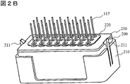
- FIG. 2B shows a state where the solution storage device of this example is assembled.
- a container 200 is stored in the container storage unit 210.
- the hook 211 of the container storage unit 210 is engaged with the edge of the upper surface of the container 200.
- the container 200 is fixed in the container storage unit 210.
- the upper surface of the container 200 is covered with a lid 230, and an evaporation preventing film 220 is attached to the upper surface of the lid 230.
- one container 200 is stored in the container storage unit 210, but a plurality of containers 200 may be stored side by side.
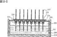
- FIG. 2C shows the use state of the solution storage device of this example.
- a container 200 is mounted in a container storage unit 210, and a solution 301 such as a buffer solution, a reagent solution, a cleaning solution, and a cleaning waste solution is stored in a reservoir unit 201 of the container 200.
- the protrusion 222 of the evaporation preventing film 220 is engaged with the hole 231 of the lid 230.
- the capillary cathode end 117 passes through the capillary hole 221 of the evaporation preventing film 220.
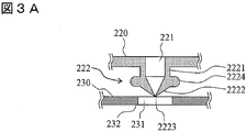
- a protrusion 222 is formed on the lower surface of the evaporation preventing film 220 so as to surround the capillary hole 221.
- the protruding portion 222 is formed on the cylindrical portion 2221, a protruding flange portion 2224 formed on the outer periphery of the cylindrical portion 2221, a conical bottom portion 2222 connected to the tip of the cylindrical portion 2221, and a lower end of the bottom portion.
- a tip hole 2223 is formed on the cylindrical portion 2221, a protruding flange portion 2224 formed on the outer periphery of the cylindrical portion 2221, a conical bottom portion 2222 connected to the tip of the cylindrical portion 2221, and a lower end of the bottom portion.
- the cross-sectional shape of the flange portion 2224 of the protrusion 222 is preferably an arc shape, but may be a rectangle. Since the flange portion 2224 is undercut with respect to the drawing direction in manufacturing, the collar portion 2224 is drawn out by utilizing deformation of the elastic body.
- the capillary hole 221 extends to the inside of the cylindrical portion 2221.
- a taper is formed on the inner surface of the capillary hole 221, and the inner diameter is small.
- the capillary hole 221 is connected to the tip hole 2223.
- the outer diameter of the cylindrical portion 2221 of the protruding portion 222 is equal to or slightly smaller than the inner diameter of the hole 231 of the lid 230.
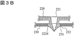
- the outer diameter of the flange 2224 is slightly larger than the inner diameter of the hole 231 of the lid 230. Therefore, as shown in FIG. 3B, when the protrusion 222 of the evaporation preventing film 220 is inserted into the hole 231 of the lid 230, the cylinder of the protrusion 222 until the flange 2224 can be inserted into the hole 231 of the lid 230.
- the part 2221 needs to be elastically deformed. As shown in FIG.
- the protrusion 222 cannot be removed from the hole 231 of the lid 230 unless the protrusion 222 of the evaporation preventing film 220 is deformed with a special force.
- the flange portion 2224 of the protrusion 222 of the evaporation prevention film 220 and the edge 232 of the hole 231 of the lid 230 constitute an engagement portion between the evaporation prevention film 220 and the lid 230.
- the inner diameter of the capillary hole 221 is larger than the outer diameter of the capillary cathode end 117, but the inner diameter of the tip hole 2223 is slightly smaller than the outer diameter of the capillary cathode end 117.
- the capillary cathode end 117 is inserted into the capillary hole 221 of the evaporation preventing film 220 and further penetrated through the tip hole 2223 of the protrusion 222 of the evaporation preventing film 220, the capillary cathode end 117 is surrounded by the elastic force of the tip hole 2223. It is tightened by. That is, there is no gap between the capillary cathode end 117 and the tip hole 2223. Therefore, the evaporated liquid in the reservoir unit 201 does not leak from the periphery of the capillary cathode end 117. That is, the inside of the reservoir portion 201 of the container 200 is completely sealed.
- the evaporation prevention film 220 be formed of a transparent or translucent elastic material so that the deformation state of the protrusion 222 can be visually recognized.
- a transparent silicone rubber is desirable as a material for the evaporation preventing film 220.
- the container 200 and the lid 230 may be formed of a transparent material. Thereby, the deformation state of the protrusion 222 can be confirmed from the outside.
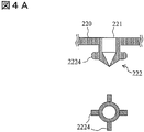
- FIG. 4A and 4B show an example of the flange 2224 of the protrusion 222 of the evaporation preventing film 220.
- the flange 2224 may be formed by a plurality of protrusions extending radially outward, but as shown in FIG. 4B, a band-shaped or donut-shaped protrusion extending along the circumferential direction. May be formed.
- the function of the protrusion 222 of the evaporation preventing film 220 in the solution storage device of this example will be described.
- the capillary cathode end 117 is inserted into the capillary hole 221 of the evaporation preventing film 220, the capillary cathode end 117 is moved downward with respect to the evaporation preventing film 220 and the lid 230.
- a frictional force is generated between the capillary cathode end 117 and the tip hole 2223 of the protrusion 222 of the evaporation preventing film 220.
- This frictional force acts on the capillary cathode end 117 to prevent insertion, and at the same time presses the evaporation preventing film 220 downward.
- the evaporation preventing film 220 is pressed against the lid 230 by this downward force.
- the evaporation preventing film 220 is supported by the lid 230 and does not move downward.
- the capillary cathode end 117 When the capillary cathode end 117 is pulled out from the capillary hole 221 of the evaporation preventing film 220, the capillary cathode end 117 is similarly moved upward and perpendicular to the evaporation preventing film 220 and the lid 230. A frictional force is generated between the capillary cathode end 117 and the tip hole 2223 of the protrusion 222 of the evaporation preventing film 220. This frictional force acts on the capillary cathode end 117 so as to prevent pulling out, and at the same time pushes the evaporation preventing film 220 upward. The evaporation prevention film 220 is pulled up in the direction away from the lid 230 by this upward force.
- the flange 2224 of the protrusion 222 of the evaporation preventing film 220 is engaged with the edge 232 of the hole 231 of the lid 230. Therefore, the evaporation preventing film 220 cannot move further away from the lid 230.
- the outer diameter of the capillary cathode end 117 is smaller than the inner diameter of the tip hole 2223 of the protrusion 222 of the evaporation preventing film 220, but larger than the inner diameter of the capillary hole 221. Therefore, when the capillary cathode end 117 is pulled out or inserted, the frictional force acting on the capillary cathode end 117 is only between the capillary cathode end 117 and the tip hole 2223 of the protrusion 222 of the evaporation preventing film 220. Yes, relatively small. Therefore, the force required to pull out or insert the capillary cathode end 117 may be small.
- the excessive deformation of the evaporation preventing film 220 is prevented by the engagement between the flange 2224 of the protrusion 222 of the evaporation preventing film 220 and the edge 232 of the hole 231 of the lid 230. Therefore, the thickness of the evaporation preventing film 220 can be reduced. Further, the evaporation preventing film 220 can be made of a relatively soft material. In this way, by forming the evaporation preventing film 220 from a relatively soft elastic material, it is possible to reduce the frictional force when the capillary cathode end is pulled out or inserted.
- the solution storage device of this example includes a container 200, a container storage unit 210, an evaporation preventing film 220, and a lid 230.
- the protrusion 203 formed on the outer surface of the container 200 is engaged with the protrusion 213 formed on the inner surface of the container storage unit 210, whereby the container 200 is fixed in the container storage unit 210.
- the container 200 and the lid 230 are joined using an adhesive or by ultrasonic fusion.
- the lid 230 is provided with a plurality of holes 231.
- the evaporation prevention film 220 has a capillary hole 221 through which the capillary cathode end passes and a protrusion 222.
- the structure of the capillary hole 221 and the protrusion 222 has been described with reference to FIGS. 3A, 3B and 3C, 4A and 4B.
- the engagement portion between the evaporation preventing film 220 and the lid 230 is constituted by the flange portion 2224 of the protrusion 222 of the evaporation preventing film 220 and the edge 232 of the hole 231 of the lid 230.
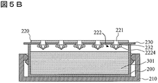
- FIG. 5B shows a state where the evaporation preventing film 220 is attached to the upper surface of the lid 230.
- the solution storage device of this example includes a container 200, a container storage unit 210, a plurality of evaporation prevention films 220a to 200d, and a lid 230.
- the protrusion 203 formed on the outer surface of the container 200 is engaged with the protrusion 213 formed on the inner surface of the container storage unit 210, whereby the container 200 is fixed in the container storage unit 210.
- the container 200 and the lid 230 are joined using an adhesive or by ultrasonic fusion.
- the lid 230 is provided with a plurality of holes 231.
- the solution storage device of this example has a plurality of evaporation prevention films 220a to 200d, and each evaporation prevention film has at least one capillary hole 221 and a protrusion 222.
- the evaporation preventing film may be provided for each capillary.
- the structure of the capillary hole 221 and the protrusion 222 has been described with reference to FIGS. 3A, 3B and 3C, 4A and 4B.
- the engagement portion between the evaporation preventing film 220 and the lid 230 is constituted by the flange portion 2224 of the protrusion portion 222 of the evaporation preventing film and the edge 232 of the hole 231 of the lid 230.
- FIG. 5B shows a state where a plurality of evaporation prevention films 220a to 200d are mounted on the upper surface of the lid 230.
- the solution storage device of this example includes a container 200, a container storage unit 210, an evaporation preventing film 220, and a lid 230.
- the protrusion 203 formed on the outer surface of the container 200 is engaged with the protrusion 213 formed on the inner surface of the container storage unit 210, whereby the container 200 is fixed in the container storage unit 210.
- the evaporation prevention film 220 has a capillary hole 221 through which the capillary cathode end passes and a protrusion 222.
- the structure of the capillary hole 221 and the protrusion 222 has been described with reference to FIGS. 3A, 3B and 3C, 4A and 4B.
- the engagement portion between the evaporation preventing film 220 and the lid 230 is constituted by the flange portion 2224 of the protrusion 222 of the evaporation preventing film 220 and the edge 232 of the hole 231 of the lid 230.
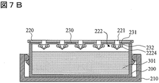
- FIG. 7B shows a state where the evaporation preventing film 220 is attached. As shown, the upper edge 205 of the container 200 is engaged with the groove 225 of the evaporation preventing film 220. Therefore, in this example, the evaporation preventing film 220 is fixed by the container 200.
- the flange part 2224 of the protrusion part 222 of the evaporation prevention film and the edge 232 of the hole 231 of the lid 230 are engaged with each other. It is possible to reliably prevent the membrane from coming off the container 200.
- an engaging portion constituted by the flange portion 2224 of the protruding portion 222 and the edge 232 of the hole 231 of the lid 230 is provided for each capillary. Therefore, the effect of preventing the evaporation preventing film from being detached from the container 200 can be expected regardless of the number of capillaries.
- the lid supports the downward force applied to the evaporation preventing film when the capillary is inserted. Therefore, the evaporation preventing film is not deformed and does not touch the solution. Therefore, the thickness of the evaporation preventing film can be reduced. Therefore, the size of the capillary cathode end is not increased. Further, when the number of capillaries increases, the area of the evaporation preventing film increases. Even in this case, the evaporation preventing film can be reliably held by the lid.
- the solution storage device of this example includes a container 200, a container storage unit 210, an evaporation prevention film 220, a seal member 250, and a lid 230.
- the lid 230 is detachably attached to the container 200.
- Fastening members 202 are mounted on both sides of the container 200.
- the fastening member 202 may be a snap-type fastening device using elastic deformation of resin.
- Such fasteners are known for use in fastening food container lids, and can have a variety of configurations.
- a seal member 250 is inserted between the lid 230 and the container 200.
- the seal member 250 is a seal member made of rubber, resin, or the like, and is used in various fields as a gasket, packing, or the like.
- a groove for engaging the seal member 250 may be formed on the lower surface of the lid 230.
- FIG. 8B shows a state where the solution storage device of this example is assembled.
- a container 200 is stored in the container storage unit 210.
- the hook 211 of the container storage unit 210 is engaged with the edge of the upper surface of the container 200.
- the container 200 is fixed in the container storage unit 210.
- FIG. 8C shows the state of use of the solution storage device of this example.
- a container 200 is mounted in a container storage unit 210, and a solution 301 such as a buffer solution, a reagent solution, a cleaning solution, and a cleaning waste solution is stored in a reservoir unit 201 of the container 200.
- the protrusion 222 of the evaporation preventing film 220 is engaged with the hole 231 of the lid 230.
- the capillary cathode end 117 passes through the capillary hole 221 of the evaporation preventing film 220.
Landscapes
- Health & Medical Sciences (AREA)
- Life Sciences & Earth Sciences (AREA)
- Molecular Biology (AREA)
- Chemical & Material Sciences (AREA)
- Chemical Kinetics & Catalysis (AREA)
- Electrochemistry (AREA)
- Physics & Mathematics (AREA)
- Analytical Chemistry (AREA)
- Biochemistry (AREA)
- General Health & Medical Sciences (AREA)
- General Physics & Mathematics (AREA)
- Immunology (AREA)
- Pathology (AREA)
- Investigating, Analyzing Materials By Fluorescence Or Luminescence (AREA)
Abstract
キャピラリ電気泳動装置の溶液収納装置において、キャピラリ陰極端を長くすることなく、キャピラリ抜き差しの際、蒸発防止膜を容器に対して確実に保持する。溶液収納装置は、試料又は溶液を収容する容器と、キャピラリが貫通するための孔を有し容器を覆う蓋と、キャピラリが貫通するためのキャピラリ孔を有する蒸発防止膜と、容器を収容する容器収納部とを有する。蒸発防止膜は、キャピラリ孔の周囲に形成された突起部を有し、蒸発防止膜を蓋の上に配置したとき、蒸発防止膜の突起部は蓋の孔に係合し、それによって蒸発防止膜は、蓋に支持されるように構成されている。
Description
本発明は、DNA、蛋白質などの試料を電気泳動により分離及び分析するキャピラリ電気泳動装置に関し、特に、試料溶液、バッファ溶液、試薬溶液、洗浄液、等の溶液を収容する溶液収納部に関する。
キャピラリ電気泳動装置にて用いられる試料、試薬、バッファ、洗浄液等の溶液は、蒸発防止膜によって密閉された容器に収容されている。キャピラリは、蒸発防止膜に開けられた孔を通って容器内の液体と接触する。
蒸発防止膜は弾性材料からなる。キャピラリが蒸発防止膜の孔に貫通している時、孔は弾性力によって収縮し、蒸発防止膜はキャピラリの周囲を密閉する。キャピラリを蒸発防止膜の孔に通す時、キャピラリと孔の間の摩擦力に抗して、キャピラリを孔に押し込むための駆動力が必要となる。また、キャピラリを蒸発防止膜の孔から引き抜く時も、摩擦力に抗してキャピラリを引き抜くための駆動力が必要となる。キャピラリを蒸発防止膜の孔から引き抜く時、キャピラリと孔の間の摩擦力によって、蒸発防止膜は容器から持ち上げられる。この摩擦力が大きい場合には、蒸発防止膜ばかりでなく容器が持ち上げられることがある。
この問題を解決するために、特許文献1に記載されたキャピラリ電気泳動装置では、ストリッパが用いられる。蒸発防止膜をストリッパで下方に押さえつけることにより、蒸発防止膜からキャピラリを引き抜くときに、蒸発防止膜や容器が持ち上がらないようにしている。
また、特許文献2に記載されたキャピラリ電気泳動装置では、キャピラリの抜き差しを行っても、蒸発防止膜が、試料が入っているバッファ容器等の各種容器から、あるいは、容器が容器収納部から外れないように、係合部が配置されている。
本願発明者がキャピラリ電気泳動装置における溶液収納部について鋭意検討した結果、次の知見を得るに至った。特許文献1に記載されたキャピラリ電気泳動装置では、セプタとロードヘッダの間にストリッパを設ける。従って、ストリッパ分のスペースを確保する必要があり、キャピラリ陰極端が溶液に浸かるためには、その分だけ、キャピラリ陰極端を長くしなければならない。
特許文献2に記載されたキャピラリ電気泳動装置では、蒸発防止膜を容器外縁で保持している。したがって、蒸発防止膜と溶液の間の距離を確保する必要があり、その分だけキャピラリ陰極端を長くしなければならない。
キャピラリ陰極端を長くすると、陰極端が外気に触れる範囲が増え、陰極端間の温度差が大きくなり、キャピラリ間における測定結果のばらつきが大きくなる可能性がある。
本発明の目的は、キャピラリ電気泳動装置の溶液収納装置において、キャピラリ陰極端を長くすることなく、キャピラリ抜き差しの際、蒸発防止膜を容器に対して確実に保持することにある。
本発明は、キャピラリ電気泳動装置の溶液収納装置に関する。本発明において、キャピラリが貫通するためのキャピラリ孔を有する蒸発防止膜は、キャピラリ孔の周囲に形成された突起部を有し、蒸発防止膜を蓋の上に配置したとき、蒸発防止膜の突起部は蓋の孔に係合し、それによって蒸発防止膜は、蓋に支持されるように構成されている。
本発明によると、キャピラリ電気泳動装置の溶液収納装置において、キャピラリ陰極端を長くすることなく、キャピラリ抜き差しの際、蒸発防止膜を容器に対して確実に保持することができる。
101…キャピラリ、102…ロードヘッダ、103…ポンプ機構、104…光学系、105…高圧電源、106…オーブン、107…オートサンプラ、108…シリンジ、109…ブロック、110…逆支弁、111…ポリマー容器、112…陽極バッファ容器、113…陽極電極、114…陰極電極、115…温度制御板、116…キャピラリヘッド、117…キャピラリ陰極端、200…容器、201…リザーバ部、202…締結部材、203…突起部、205…上縁、210…容器収納部、211…フック、220…蒸発防止膜、221…キャピラリ孔、222…突起部、230…蓋、231…孔、232…縁、250…シール部材、301…溶液、2221…円筒部、2222…底部、2223…先端孔、2224…鍔部
図1はキャピラリ電気泳動装置の例の概要を示す。本例のキャピラリ電気泳動装置は、単数又は複数本のキャピラリ101を含むキャピラリアレイ、キャピラリ101をポリマーに注入するためのポンプ機構103、キャピラリ101内のサンプルに光を照射し、サンプルの蛍光を検出するための光学系104、キャピラリ101に高電圧を加えるための高圧電源105、キャピラリ101を恒温に保つためのオーブン106、試料、溶液等が入った容器を搬送するためのオートサンプラ107を有する。
キャピラリ101は交換可能な部材であり、測定手法を変更する場合や、キャピラリ101に破損や品質の劣化がみられたときに、交換する。キャピラリ101は、内径が数十から数百ミクロン、外径が数百ミクロンのガラス管で構成され、表面はポリイミドでコーティングされている。キャピラリ101の内部は、電気泳動時に泳動速度差を与えるための分離媒体が充填される。分離媒体は流動性と、非流動性の双方が存在するが、本実施例では流動性のポリマーを用いる。
キャピラリ101の一端にはキャピラリヘッド116が設けられ、他端にはキャピラリ陰極端117が形成されている。キャピラリヘッド116は、キャピラリ101の端部を束ねたものであり、ポンプ機構103とキャピラリ101を接続させる機能を有する。キャピラリ陰極端117は、試料、溶液等に接触する。キャピラリ陰極端側では、キャピラリ101はロードヘッダ102によって固定されている。ロードヘッダ102には陰極電極114が設けられている。
光学系104は、照射系と検出系からなる。光学系104は、キャピラリ101のポリイミト゛被膜が除去されている部分、即ち、検出部に励起光を照射する機能を有する。検出系は、キャピラリ101の検出部内のサンプルからの蛍光を検出する機能を有する。検出系によって検出された光によって試料を分析する。
ポンプ機構103は、シリンジ108、ブロック109、逆支弁110、ポリマー容器111及び陽極バッファ容器112を有する。キャピラリヘッド116をブロック109に接続することで、キャピラリ101とブロック109内の流路が接続される。シリンジ108の操作により、ポリマー容器111内のポリマーがブロック109内の流路を経由してキャピラリ101に充填され又は詰め替えられる。キャピラリ101中のポリマーの詰め替えは測定の性能を向上するために測定毎に実施される。
陽極バッファ容器112には陽極電極113が配置されている。高圧電源105は、陽極電極113と陰極電極114の間に高圧電圧を印加する。
オーブン106は、断熱材とヒータが取り付けられた温度制御板115より、キャピラリアレイ102を平面状に挟み込んで、キャピラリの温度を一定に保つ。温度制御板にはフィードバック用の温度センサが取り付けられている。また、キャピラリアレイのロードヘッダ102をオーブンに固定することで、キャピラリヘッド116の先端を所望の位置に固定することができる。
オートサンプラ107は、移動ステージを移動させるための3つの電動モータとリニアガイドを備えており、移動ステージを上下、左右、および奥行きの3軸方向に移動可能である。移動ステージは、バッファ容器、洗浄容器、廃液容器およびサンプルプレートを必要に応じてキャピラリ陰極端117(キャピラリ電極)まで搬送できる。
図2A、図2B、及び、図2Cを参照してキャピラリ電気泳動装置によって用いられる溶液収納装置の第1の例を説明する。図2Aに示すように、本例の溶液収納装置は、容器200、容器収納部210、蒸発防止膜220、及び、蓋230を有する。
容器200は、試料溶液、バッファ溶液、試薬溶液、洗浄液、等の溶液を収納するリザーバ部201を備える。本例では、容器200と蓋230は接着剤を用いて、又は、超音波融着によって接合されている。容器収納部210の両側には、フック211が形成されている。蓋230には複数の孔231が設けられている。蓋230の両側には、切り欠き235が形成されている。
蒸発防止膜220は、キャピラリ陰極端117が貫通するためのキャピラリ孔221と、突起部222を有する。突起部222は、蒸発防止膜220の下面にて、キャピラリ孔221を囲むように突出している。キャピラリ孔221及び突起部222は、蓋230の孔231に対応して設けられている。蓋230の下面における孔231の縁232は、蒸発防止膜220の突起部222との間で係合部を形成するが、これについては、後に説明する。蒸発防止膜220は弾性材料、例えば、ゴム、樹脂等によって形成されている。
図2Bは、本例の溶液収納装置が組み立てられた状態を示す。容器収納部210に容器200が収納されている。容器収納部210のフック211は、容器200の上面の縁に係合している。こうして、容器200は、容器収納部210内に固定される。
容器200の上面は蓋230によって覆われており、蓋230の上面に、蒸発防止膜220が装着されている。図2Bの例では、容器収納部210に1個の容器200が収納されているが、複数の容器200を並べて収納することもできる。
図2Cは、本例の溶液収納装置の使用状態を示す。図示のように、容器収納部210内に容器200が装着され、容器200のリザーバ部201にバッファ溶液、試薬溶液、洗浄液、洗浄廃液等の溶液301が収納されている。蓋230の孔231に、蒸発防止膜220の突起部222が係合している。キャピラリ陰極端117は、蒸発防止膜220のキャピラリ孔221を貫通している。
図3A、図3B及び図3Cを参照して、蒸発防止膜220のキャピラリ孔221及び突起部222の構造を説明する。図3Aに示すように、蒸発防止膜220の下面に、キャピラリ孔221を囲むように突起部222が形成されている。突起部222は、円筒部2221と、円筒部2221の外周に形成された突起状の鍔部2224と、円筒部2221の先端に接続された円錐状の底部2222と、底部の下端に形成された先端孔2223と、を有する。
突起部222の鍔部2224の断面形状は円弧形状が望ましいが、矩形でもよい。鍔部2224は、製造上、成形における抜き方向に対し、アンダーカットとなるので、弾性体の変形を利用して抜き取られる。
キャピラリ孔221は、円筒部2221の内部まで延びている。底部2222では、キャピラリ孔221の内面にテーパが形成されており、内径が小さくなっている。キャピラリ孔221は先端孔2223に接続されている。
突起部222の円筒部2221の外径は、蓋230の孔231の内径に等しいか、又は、それより僅かに小さい。鍔部2224の外径は、蓋230の孔231の内径より僅かに大きい。従って、図3Bに示すように、蒸発防止膜220の突起部222を、蓋230の孔231に挿入するとき、鍔部2224が蓋230の孔231に挿入可能となるまで、突起部222の円筒部2221を弾性変形させる必要がある。図3Cに示すように、蒸発防止膜220の突起部222の鍔部2224が、蓋230の孔231を通過したら、突起部222の円筒部2221は元の形状に戻り、鍔部2224は蓋230の孔231より突出する。こうして、図3Cに示すように、蒸発防止膜220の突起部222が、蓋230の孔231に挿入された状態では、突起部222の鍔部2224が、蓋230の孔231の縁232に当接するため、蒸発防止膜220を蓋230より引き離すことはできない。即ち、蒸発防止膜220の突起部222を特別な力で変形させない限り、突起部222を蓋230の孔231から取り外すことはできない。本例によると、蒸発防止膜220の突起部222の鍔部2224と、蓋230の孔231の縁232によって、蒸発防止膜220と蓋230の間の係合部を構成する。
キャピラリ孔221の内径は、キャピラリ陰極端117の外径より大きいが、先端孔2223の内径は、キャピラリ陰極端117の外径より僅かに小さい。キャピラリ陰極端117を蒸発防止膜220のキャピラリ孔221に挿入し、更に、蒸発防止膜220の突起部222の先端孔2223を貫通させると、キャピラリ陰極端117の周囲は、先端孔2223の弾性力によって、締め付けられる。即ち、キャピラリ陰極端117と先端孔2223の間に隙間は生じない。従って、キャピラリ陰極端117の周囲から、リザーバ部201の蒸発液が漏洩することはない。即ち、容器200のリザーバ部201内は完全に密閉される。
キャピラリ陰極端117が蒸発防止膜220のキャピラリ孔221に挿入されていないときも、蒸発防止膜220の突起部222の先端孔2223は、弾性力によって収縮し、閉じた状態となる。従って、キャピラリ陰極端117が挿入されていないときも、容器200のリザーバ部201内は完全に密閉されている。
蒸発防止膜220の突起部222を、蓋230の孔231に挿入したのち、突起部222が元の形状に戻らないと、蒸発防止膜220を蓋230に保持することはできない。そのため、突起部222の変形状態が視認できるよう、蒸発防止膜220は、透明又は半透明の弾性材料によって形成することが望ましい。耐薬品性などを考慮すると、蒸発防止膜220の材料として、透明のシリコーンゴムが望ましい。また、容器200及び蓋230を、同様に、透明な材料によって形成してもよい。それによって、外側から突起部222の変形状態を確認できる。
図4A及び図4Bは、蒸発防止膜220の突起部222の鍔部2224の例を示す。鍔部2224は、図4Aに示すように、半径方向外方に延びる複数の突起部によって形成されてよいが、図4Bに示すように、円周方向に沿って延びる帯状又はドーナツ状の突起部によって形成されてよい。
本例の溶液収納装置において、蒸発防止膜220の突起部222の機能を説明する。キャピラリ陰極端117を、蒸発防止膜220のキャピラリ孔221に挿入するとき、キャピラリ陰極端117を下方に蒸発防止膜220及び蓋230に対して垂直に移動させる。キャピラリ陰極端117と、蒸発防止膜220の突起部222の先端孔2223の間に摩擦力が発生する。この摩擦力は、キャピラリ陰極端117に対して、挿入を妨げるように作用すると同時に、蒸発防止膜220を下方に押圧する。蒸発防止膜220は、この下方の力によって、蓋230に押し付けられる。しかしながら、蒸発防止膜220は、蓋230によって支持されており、下方に移動することはない。
キャピラリ陰極端117を、蒸発防止膜220のキャピラリ孔221から引き抜くとき、同様に、キャピラリ陰極端117を上方に、蒸発防止膜220及び蓋230に対して垂直に移動させる。キャピラリ陰極端117と、蒸発防止膜220の突起部222の先端孔2223の間に摩擦力が発生する。この摩擦力は、キャピラリ陰極端117に対して、引き抜きを妨げるように作用すると同時に、蒸発防止膜220を上方に押し上げる。蒸発防止膜220は、この上方の力によって、蓋230から離れる方向に引き上げられる。しかしながら、蒸発防止膜220の突起部222の鍔部2224は、蓋230の孔231の縁232に係合している。そのため、蒸発防止膜220は、それ以上、蓋230から離れる方向に移動することはできない。
本例のキャピラリ電気泳動装置の溶液収納装置では、キャピラリ陰極端117の外径は、蒸発防止膜220の突起部222の先端孔2223の内径より小さいが、キャピラリ孔221の内径より大きい。従って、キャピラリ陰極端117を引き抜き、又は、差し込むとき、キャピラリ陰極端117に作用する摩擦力は、キャピラリ陰極端117と、蒸発防止膜220の突起部222の先端孔2223の間に摩擦力のみであり、比較的小さい。そのため、キャピラリ陰極端117を引き抜き、又は、差し込むために必要な力が少なくてよい。
本例によると、蒸発防止膜220の突起部222の鍔部2224と、蓋230の孔231の縁232の係合によって、蒸発防止膜220の過度な変形は防止される。そのため、蒸発防止膜220の厚さを小さくすることができる。更に、蒸発防止膜220を比較的軟らかい材料によって構成することができる。こうして、蒸発防止膜220を比較的軟らかい弾性材料によって形成することにより、キャピラリ陰極端を引き抜き、又は、差し込むときの摩擦力を軽減できる。
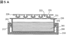
図5A及び図5Bを参照して、キャピラリ電気泳動装置によって用いられる溶液収納装置の第2の例を説明する。図5Aに示すように、本例の溶液収納装置は、容器200、容器収納部210、蒸発防止膜220、及び、蓋230を有する。容器200の外面に形成された突起部203と容器収納部210の内面に形成された突起部213が係合しており、それによって、容器200は容器収納部210内に固定されている。
容器200と蓋230は接着剤を用いて、又は、超音波融着によって接合されている。蓋230には複数の孔231が設けられている。
蒸発防止膜220は、キャピラリ陰極端が貫通するためのキャピラリ孔221と、突起部222を有する。キャピラリ孔221及び突起部222の構造は、図3A、図3B及び図3C、図4A及び図4Bを参照して説明した。本例でも、蒸発防止膜220の突起部222の鍔部2224と、蓋230の孔231の縁232によって、蒸発防止膜220と蓋230の間の係合部を構成する。図5Bは、蓋230の上面に、蒸発防止膜220が装着された状態を示す。
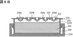
図6A及び図6Bを参照して、キャピラリ電気泳動装置によって用いられる溶液収納装置の第3の例を説明する。図6Aに示すように、本例の溶液収納装置は、容器200、容器収納部210、複数の蒸発防止膜220a~200d、及び、蓋230を有する。容器200の外面に形成された突起部203と容器収納部210の内面に形成された突起部213が係合しており、それによって、容器200は容器収納部210内に固定されている。容器200と蓋230は接着剤を用いて、又は、超音波融着によって接合されている。蓋230には複数の孔231が設けられている。
本例の溶液収納装置は、複数の蒸発防止膜220a~200dを有し、各蒸発防止膜は少なくとも1つのキャピラリ孔221と突起部222を有する。蒸発防止膜は、キャピラリ毎に設けてもよい。キャピラリ孔221及び突起部222の構造は、図3A、図3B及び図3C、図4A及び図4Bを参照して説明した。本例でも、蒸発防止膜の突起部222の鍔部2224と、蓋230の孔231の縁232によって、蒸発防止膜220と蓋230の間の係合部を構成する。図5Bは、蓋230の上面に、複数の蒸発防止膜220a~200dが装着された状態を示す。
図7A及び図7Bを参照して、キャピラリ電気泳動装置によって用いられる溶液収納装置の第4の例を説明する。図7Aに示すように、本例の溶液収納装置は、容器200、容器収納部210、蒸発防止膜220、及び、蓋230を有する。容器200の外面に形成された突起部203と容器収納部210の内面に形成された突起部213が係合しており、それによって、容器200は容器収納部210内に固定されている。
蒸発防止膜220は、キャピラリ陰極端が貫通するためのキャピラリ孔221と、突起部222を有する。キャピラリ孔221及び突起部222の構造は、図3A、図3B及び図3C、図4A及び図4Bを参照して説明した。本例でも、蒸発防止膜220の突起部222の鍔部2224と、蓋230の孔231の縁232によって、蒸発防止膜220と蓋230の間の係合部を構成する。
容器200の上縁205は、蓋230を囲むように、蓋230より上方に突出している。蒸発防止膜220の下面には溝225が形成されている。図7Bは、蒸発防止膜220が装着された状態を示す。図示のように、蒸発防止膜220の溝225に、容器200の上縁205が係合している。従って、本例では、蒸発防止膜220は、容器200よって固定される。
キャピラリ電気泳動装置の溶液収納装置では、キャピラリを蒸発防止膜から引き抜くとき、蒸発防止膜の突起部222の鍔部2224と蓋230の孔231の縁232は互いに係合しているため、蒸発防止膜が容器200から外れることを確実に防止することができる。また、突起部222の鍔部2224と蓋230の孔231の縁232によって構成される係合部は、キャピラリ毎に設けられる。従って、キャピラリ本数の多寡に関係なく、蒸発防止膜が容器200から外れることを防止する効果が期待できる。
溶液収納装置では、蓋230の上に蒸発防止膜を配置するから、キャピラリの挿入時に蒸発防止膜にかかる下向きの力を蓋が支持する。そのため蒸発防止膜が変形して溶液に触れることはない。そのため、蒸発防止膜の厚さを小さくすることができる。そのため、キャピラリ陰極端の寸法が長くなることはない。また、キャピラリの本数が増えた場合、蒸発防止膜の面積は大きくなる。この場合でも、蒸発防止膜を蓋によって確実に保持することができる。
図8A、図8B、及び、図8Cを参照してキャピラリ電気泳動装置によって用いられる溶液収納装置の第5の例を説明する。図8Aに示すように、本例の溶液収納装置は、容器200、容器収納部210、蒸発防止膜220、シール部材250、及び、蓋230を有する。
本例では、蓋230は容器200に取り外し可能に装着されている。容器200の両側に締結部材202が装着されている。締結部材202は樹脂の弾性変形を利用したスナップ型の締結器具であってよい。このような締結器具は、食品容器の蓋を締結する用途で知られており、様々な構造が可能である。蓋230と容器200の間にシール部材250が挿入されている。シール部材250は、ゴム、樹脂等によって構成されたシール用の部材であり、ガスケット、パッキン等として様々な分野で用いられている。尚、蓋230の下面に、シール部材250が係合するための溝が形成されてよい。
図8Bは、本例の溶液収納装置が組み立てられた状態を示す。容器収納部210に容器200が収納されている。容器収納部210のフック211は、容器200の上面の縁に係合している。こうして、容器200は、容器収納部210内に固定される。
図8Cは、本例の溶液収納装置の使用状態を示す。図示のように、容器収納部210内に容器200が装着され、容器200のリザーバ部201にバッファ溶液、試薬溶液、洗浄液、洗浄廃液等の溶液301が収納されている。蓋230の孔231に、蒸発防止膜220の突起部222が係合している。キャピラリ陰極端117は、蒸発防止膜220のキャピラリ孔221を貫通している。
本発明は上述の実施例に限定されるものではなく、請求の範囲に記載された発明の範囲にて様々な変更が可能であることは当業者に容易に理解されよう。
Claims (20)
- 1本又は複数本のキャピラリと、前記キャピラリの両端に電圧を印加する電源と、前記キャピラリ内にて泳動分離された試料に励起光を照射し、試料からの蛍光を検出する光学系と、試料又は溶液が収容された溶液収納装置と、該溶液収納装置を搬送するオートサンプラと、を有するキャピラリ電気泳動装置において、
前記溶液収納装置は、試料又は溶液を収容する容器と、前記キャピラリが貫通するための孔を有し前記容器を覆う蓋と、前記キャピラリが貫通するためのキャピラリ孔を有する蒸発防止膜と、前記容器を収容する容器収納部とを有し、前記蒸発防止膜は、前記キャピラリ孔の周囲に形成された突起部を有し、前記蒸発防止膜を前記蓋の上に配置したとき、前記蒸発防止膜の突起部は前記蓋の孔に係合し、それによって前記蒸発防止膜は、前記蓋に支持されるように構成されていることを特徴とするキャピラリ電気泳動装置。 - 請求項1記載のキャピラリ電気泳動装置において、
前記突起部は、前記キャピラリ孔の縁に形成された円筒部と、該円筒部の外周に形成された突起状の鍔部と、下端に形成された先端孔と、を有し、前記キャピラリ孔は、前記円筒部の内部まで延びており、更に、前記先端孔に接続されていることを特徴とするキャピラリ電気泳動装置。 - 請求項2記載のキャピラリ電気泳動装置において、
前記突起部の鍔部の外径は、前記蓋の孔の内径より大きいことを特徴とするキャピラリ電気泳動装置。 - 請求項2記載のキャピラリ電気泳動装置において、
前記突起部の円筒部の外径は、前記蓋の孔の内径に等しいか、又は、それより小さいことを特徴とするキャピラリ電気泳動装置。 - 請求項2記載のキャピラリ電気泳動装置において、
前記突起部の先端孔の内径は、前記キャピラリの外径より小さく、前記蒸発防止膜のキャピラリ孔の内径は、前記キャピラリの外径より大きいことを特徴とするキャピラリ電気泳動装置。 - 請求項2記載のキャピラリ電気泳動装置において、
前記突起部は前記円筒部と前記先端孔の間を接続する円錐状の底部を有し、該底部では、前記キャピラリ孔の内面はテーパを有することを特徴とするキャピラリ電気泳動装置。 - 請求項1記載のキャピラリ電気泳動装置において、
前記蒸発防止膜は複数の蒸発防止膜によって構成されており、前記複数の蒸発防止膜の各々には少なくとも1つの前記キャピラリ孔及び突起部が設けられていることを特徴とするキャピラリ電気泳動装置。 - 請求項7記載のキャピラリ電気泳動装置において、
前記複数の蒸発防止膜の各々には単一の前記キャピラリ孔及び突起部が設けられていることを特徴とするキャピラリ電気泳動装置。 - 請求項1記載のキャピラリ電気泳動装置において、
前記蒸発防止膜は、弾性材料によって形成されていることを特徴とするキャピラリ電気泳動装置。 - 請求項1記載のキャピラリ電気泳動装置において、
前記蒸発防止膜は、シリコンゴムによって形成されていることを特徴とするキャピラリ電気泳動装置。 - 請求項1記載のキャピラリ電気泳動装置において、
前記蓋は前記容器に接着剤を用いて、又は、超音波融着によって接合されていることを特徴とするキャピラリ電気泳動装置。 - 請求項1記載のキャピラリ電気泳動装置において、
前記蓋はスナップ型の締結器具によって前記容器に固定されていることを特徴とするキャピラリ電気泳動装置。 - 請求項1記載のキャピラリ電気泳動装置において、
前記蒸発防止膜には周状に延びる溝を有し、該溝に前記容器の上端が係合するように構成されていることを特徴とするキャピラリ電気泳動装置。 - 1本又は複数本のキャピラリと、前記キャピラリの両端に電圧を印加する電源と、前記キャピラリ内にて泳動分離された試料に励起光を照射し、試料からの蛍光を検出する光学系と、オートサンプラと、を有するキャピラリ電気泳動装置に用いるように構成された、試料又は溶液が収容された溶液収納装置において、
試料又は溶液を収容する容器と、前記キャピラリが貫通するための孔を有し前記容器を覆う蓋と、前記キャピラリが貫通するためのキャピラリ孔を有する蒸発防止膜と、前記容器を収容する容器収納部とを有し、前記蒸発防止膜は、前記キャピラリ孔の周囲に形成された突起部を有し、前記蒸発防止膜を前記蓋の上に配置したとき、前記蒸発防止膜の突起部は前記蓋の孔に係合し、それによって前記蒸発防止膜は、前記蓋に支持されるように構成されていることを特徴とする溶液収納装置。 - 請求項14記載の溶液収納装置において、
前記突起部は、前記キャピラリ孔の縁に形成された円筒部と、該円筒部の外周に形成された突起状の鍔部と、下端に形成された先端孔と、を有し、前記キャピラリ孔は、前記円筒部の内部まで延びており、更に、前記先端孔に接続されていることを特徴とする溶液収納装置。 - 請求項14記載の溶液収納装置において、
前記蒸発防止膜は、弾性材料によって形成され、
前記突起部の鍔部の外径は、前記蓋の孔の内径より大きく、
前記突起部の円筒部の外径は、前記蓋の孔の内径に等しいか、又は、それより小さく、
前記突起部の先端孔の内径は、前記キャピラリの外径より小さく、
前記蒸発防止膜のキャピラリ孔の内径は、前記キャピラリの外径より大きいことを特徴とする溶液収納装置。 - 請求項14記載の溶液収納装置において、
前記蓋は前記容器に接着剤を用いて、又は、超音波融着によって接合されていることを特徴とする溶液収納装置。 - 請求項14記載の溶液収納装置において、
前記蓋はスナップ型の締結器具によって前記容器に固定されていることを特徴とする溶液収納装置。 - 1本又は複数本のキャピラリと、前記キャピラリ内にて泳動分離された試料に励起光を照射し、試料からの蛍光を検出する光学系と、試料又は溶液が収容された溶液収納装置と、該溶液収納装置を搬送するオートサンプラと、を有するキャピラリ電気泳動装置において、
前記溶液収納装置は、試料又は溶液を収容する容器と、前記キャピラリが貫通するための孔を有し前記容器を覆う蓋と、前記キャピラリが貫通するためのキャピラリ孔を有する蒸発防止膜と、前記容器を収容する容器収納部とを有し、前記蒸発防止膜は、前記キャピラリ孔の周囲に形成された突起部を有し、前記蒸発防止膜を前記蓋の上に配置したとき、前記蒸発防止膜の突起部は前記蓋の孔に係合し、それによって前記蒸発防止膜は、前記蓋に支持されるように構成されており、
前記突起部は、前記キャピラリ孔の縁に形成された円筒部と、該円筒部の外周に形成された突起状の鍔部と、下端に形成された先端孔と、を有し、前記キャピラリ孔は、前記円筒部の内部まで延びており、更に、前記先端孔に接続されていることを特徴とするキャピラリ電気泳動装置。 - 請求項19記載のキャピラリ電気泳動装置において、
前記突起部の鍔部の外径は、前記蓋の孔の内径より大きく、
前記突起部の円筒部の外径は、前記蓋の孔の内径に等しいか、又は、それより小さく、
前記突起部の先端孔の内径は、前記キャピラリの外径より小さく、
前記蒸発防止膜のキャピラリ孔の内径は、前記キャピラリの外径より大きいことを特徴とするキャピラリ電気泳動装置。
Priority Applications (1)
| Application Number | Priority Date | Filing Date | Title |
|---|---|---|---|
| US13/263,040 US8702949B2 (en) | 2009-04-10 | 2010-04-08 | Capillary electrophoresis apparatus |
Applications Claiming Priority (2)
| Application Number | Priority Date | Filing Date | Title |
|---|---|---|---|
| JP2009-096086 | 2009-04-10 | ||
| JP2009096086A JP5004993B2 (ja) | 2009-04-10 | 2009-04-10 | キャピラリ電気泳動装置 |
Publications (1)
| Publication Number | Publication Date |
|---|---|
| WO2010117032A1 true WO2010117032A1 (ja) | 2010-10-14 |
Family
ID=42936313
Family Applications (1)
| Application Number | Title | Priority Date | Filing Date |
|---|---|---|---|
| PCT/JP2010/056357 Ceased WO2010117032A1 (ja) | 2009-04-10 | 2010-04-08 | キャピラリ電気泳動装置 |
Country Status (3)
| Country | Link |
|---|---|
| US (1) | US8702949B2 (ja) |
| JP (1) | JP5004993B2 (ja) |
| WO (1) | WO2010117032A1 (ja) |
Families Citing this family (7)
| Publication number | Priority date | Publication date | Assignee | Title |
|---|---|---|---|---|
| USD666737S1 (en) * | 2011-06-06 | 2012-09-04 | Life Technologies Corporation | Electrophoresis device |
| USD666305S1 (en) * | 2011-08-19 | 2012-08-28 | Life Technologies Corporation | Apparatus for docking and charging electrophoresis devices and portable electrophoresis system |
| EP2916135B1 (en) * | 2012-10-30 | 2018-05-02 | Hitachi High-Technologies Corporation | Reagent container and automated analyzer |
| JP2014163714A (ja) * | 2013-02-22 | 2014-09-08 | Hitachi High-Technologies Corp | 蒸発防止膜 |
| JP6047448B2 (ja) * | 2013-05-27 | 2016-12-21 | 株式会社日立ハイテクノロジーズ | キャピラリ電気泳動装置における分離媒体充填方法 |
| WO2015037308A1 (ja) * | 2013-09-12 | 2015-03-19 | 株式会社日立ハイテクノロジーズ | 電気泳動媒体容器および電気泳動装置 |
| JPWO2024247016A1 (ja) * | 2023-05-26 | 2024-12-05 |
Citations (3)
| Publication number | Priority date | Publication date | Assignee | Title |
|---|---|---|---|---|
| JP2003166976A (ja) * | 2001-12-04 | 2003-06-13 | Hitachi High-Technologies Corp | マルチキャピラリー電気泳動装置 |
| JP2008298659A (ja) * | 2007-06-01 | 2008-12-11 | Hitachi High-Technologies Corp | キャピラリ電気泳動装置 |
| JP2009042226A (ja) * | 2007-07-18 | 2009-02-26 | Hitachi High-Technologies Corp | キャピラリ電気泳動装置、及びサンプルトレイ |
Family Cites Families (7)
| Publication number | Priority date | Publication date | Assignee | Title |
|---|---|---|---|---|
| NO171008C (no) * | 1990-06-28 | 1993-01-13 | Arne Hansen | Profilformet klemmeanordning for sammenfoeyning av objekter |
| US5384024A (en) * | 1992-03-13 | 1995-01-24 | Applied Biosystems, Inc. | Capillary electrophoresis |
| US20040112749A1 (en) | 2001-03-29 | 2004-06-17 | Takehiko Shibasaki | Electrophoresis device |
| EP1625482A2 (en) * | 2003-04-11 | 2006-02-15 | Strattec Security Corporation | Ignition apparatus and method |
| WO2004096113A2 (en) * | 2003-04-28 | 2004-11-11 | Medical Instill Technologies, Inc. | Container with valve assembly for filling and dispensing substances, and apparatus and method for filling |
| US7404274B2 (en) * | 2003-11-12 | 2008-07-29 | Hayes John T | Masonry wall anchoring system |
| GB2422951B (en) * | 2005-02-07 | 2010-07-28 | Microsaic Systems Ltd | Integrated analytical device |
-
2009
- 2009-04-10 JP JP2009096086A patent/JP5004993B2/ja active Active
-
2010
- 2010-04-08 WO PCT/JP2010/056357 patent/WO2010117032A1/ja not_active Ceased
- 2010-04-08 US US13/263,040 patent/US8702949B2/en active Active
Patent Citations (3)
| Publication number | Priority date | Publication date | Assignee | Title |
|---|---|---|---|---|
| JP2003166976A (ja) * | 2001-12-04 | 2003-06-13 | Hitachi High-Technologies Corp | マルチキャピラリー電気泳動装置 |
| JP2008298659A (ja) * | 2007-06-01 | 2008-12-11 | Hitachi High-Technologies Corp | キャピラリ電気泳動装置 |
| JP2009042226A (ja) * | 2007-07-18 | 2009-02-26 | Hitachi High-Technologies Corp | キャピラリ電気泳動装置、及びサンプルトレイ |
Also Published As
| Publication number | Publication date |
|---|---|
| US8702949B2 (en) | 2014-04-22 |
| JP2010249530A (ja) | 2010-11-04 |
| JP5004993B2 (ja) | 2012-08-22 |
| US20120024707A1 (en) | 2012-02-02 |
Similar Documents
| Publication | Publication Date | Title |
|---|---|---|
| JP5004993B2 (ja) | キャピラリ電気泳動装置 | |
| CN105518446B (zh) | 电力迁移介质容器以及电力迁移装置 | |
| US9784711B2 (en) | Disposable cartridge for microfluidics systems | |
| JP5012817B2 (ja) | 反応容器プレート及び反応処理方法 | |
| CN107209149B (zh) | 电泳装置及电泳方法 | |
| JP2000314719A (ja) | 電気泳動チップ | |
| JP4947141B2 (ja) | 反応容器プレート及び反応処理方法 | |
| JPWO2008132871A1 (ja) | 反応容器プレート及び反応処理方法 | |
| JP2004226207A (ja) | 送液機構及び該送液機構を備える分析装置 | |
| WO2015005048A1 (ja) | キャピラリ電気泳動装置 | |
| JP4825731B2 (ja) | キャピラリ電気泳動装置 | |
| JP5143264B2 (ja) | 溶液収納装置 | |
| JP6047448B2 (ja) | キャピラリ電気泳動装置における分離媒体充填方法 | |
| JP2014163714A (ja) | 蒸発防止膜 | |
| JP4634469B2 (ja) | キャピラリ電気泳動装置 | |
| WO2010119805A1 (ja) | キャピラリ電気泳動装置 | |
| JP4947140B2 (ja) | 反応容器プレート及び反応処理方法 | |
| WO2021100519A1 (ja) | 流体取扱装置 | |
| JP4894685B2 (ja) | 反応容器プレート | |
| WO2016152303A1 (ja) | マイクロ流路デバイス、並びに分析装置及び分析方法 |
Legal Events
| Date | Code | Title | Description |
|---|---|---|---|
| 121 | Ep: the epo has been informed by wipo that ep was designated in this application |
Ref document number: 10761731 Country of ref document: EP Kind code of ref document: A1 |
|
| WWE | Wipo information: entry into national phase |
Ref document number: 13263040 Country of ref document: US |
|
| NENP | Non-entry into the national phase |
Ref country code: DE |
|
| 122 | Ep: pct application non-entry in european phase |
Ref document number: 10761731 Country of ref document: EP Kind code of ref document: A1 |