WO2010113644A1 - 露光方法及び露光装置 - Google Patents
露光方法及び露光装置 Download PDFInfo
- Publication number
- WO2010113644A1 WO2010113644A1 PCT/JP2010/054565 JP2010054565W WO2010113644A1 WO 2010113644 A1 WO2010113644 A1 WO 2010113644A1 JP 2010054565 W JP2010054565 W JP 2010054565W WO 2010113644 A1 WO2010113644 A1 WO 2010113644A1
- Authority
- WO
- WIPO (PCT)
- Prior art keywords
- exposed
- exposure
- shutter
- mask pattern
- pattern group
- Prior art date
- Legal status (The legal status is an assumption and is not a legal conclusion. Google has not performed a legal analysis and makes no representation as to the accuracy of the status listed.)
- Ceased
Links
Images



Classifications
-
- G—PHYSICS
- G03—PHOTOGRAPHY; CINEMATOGRAPHY; ANALOGOUS TECHNIQUES USING WAVES OTHER THAN OPTICAL WAVES; ELECTROGRAPHY; HOLOGRAPHY
- G03F—PHOTOMECHANICAL PRODUCTION OF TEXTURED OR PATTERNED SURFACES, e.g. FOR PRINTING, FOR PROCESSING OF SEMICONDUCTOR DEVICES; MATERIALS THEREFOR; ORIGINALS THEREFOR; APPARATUS SPECIALLY ADAPTED THEREFOR
- G03F7/00—Photomechanical, e.g. photolithographic, production of textured or patterned surfaces, e.g. printing surfaces; Materials therefor, e.g. comprising photoresists; Apparatus specially adapted therefor
- G03F7/70—Microphotolithographic exposure; Apparatus therefor
- G03F7/70483—Information management; Active and passive control; Testing; Wafer monitoring, e.g. pattern monitoring
- G03F7/7055—Exposure light control in all parts of the microlithographic apparatus, e.g. pulse length control or light interruption
-
- G—PHYSICS
- G03—PHOTOGRAPHY; CINEMATOGRAPHY; ANALOGOUS TECHNIQUES USING WAVES OTHER THAN OPTICAL WAVES; ELECTROGRAPHY; HOLOGRAPHY
- G03B—APPARATUS OR ARRANGEMENTS FOR TAKING PHOTOGRAPHS OR FOR PROJECTING OR VIEWING THEM; APPARATUS OR ARRANGEMENTS EMPLOYING ANALOGOUS TECHNIQUES USING WAVES OTHER THAN OPTICAL WAVES; ACCESSORIES THEREFOR
- G03B27/00—Photographic printing apparatus
- G03B27/32—Projection printing apparatus, e.g. enlarger, copying camera
- G03B27/42—Projection printing apparatus, e.g. enlarger, copying camera for automatic sequential copying of the same original
- G03B27/426—Projection printing apparatus, e.g. enlarger, copying camera for automatic sequential copying of the same original in enlargers
-
- G—PHYSICS
- G03—PHOTOGRAPHY; CINEMATOGRAPHY; ANALOGOUS TECHNIQUES USING WAVES OTHER THAN OPTICAL WAVES; ELECTROGRAPHY; HOLOGRAPHY
- G03F—PHOTOMECHANICAL PRODUCTION OF TEXTURED OR PATTERNED SURFACES, e.g. FOR PRINTING, FOR PROCESSING OF SEMICONDUCTOR DEVICES; MATERIALS THEREFOR; ORIGINALS THEREFOR; APPARATUS SPECIALLY ADAPTED THEREFOR
- G03F7/00—Photomechanical, e.g. photolithographic, production of textured or patterned surfaces, e.g. printing surfaces; Materials therefor, e.g. comprising photoresists; Apparatus specially adapted therefor
- G03F7/70—Microphotolithographic exposure; Apparatus therefor
- G03F7/70216—Mask projection systems
- G03F7/70358—Scanning exposure, i.e. relative movement of patterned beam and workpiece during imaging
-
- H—ELECTRICITY
- H10—SEMICONDUCTOR DEVICES; ELECTRIC SOLID-STATE DEVICES NOT OTHERWISE PROVIDED FOR
- H10P—GENERIC PROCESSES OR APPARATUS FOR THE MANUFACTURE OR TREATMENT OF DEVICES COVERED BY CLASS H10
- H10P76/00—Manufacture or treatment of masks on semiconductor bodies, e.g. by lithography or photolithography
- H10P76/20—Manufacture or treatment of masks on semiconductor bodies, e.g. by lithography or photolithography of masks comprising organic materials
- H10P76/204—Manufacture or treatment of masks on semiconductor bodies, e.g. by lithography or photolithography of masks comprising organic materials of organic photoresist masks
- H10P76/2041—Photolithographic processes
Definitions
- the present invention relates to an exposure method and an exposure apparatus that form different exposure patterns for a plurality of exposure areas set on an exposure object while conveying the exposure object in one direction.
- the present invention relates to an exposure method and an exposure apparatus for improving the formation efficiency.
- this type of exposure method selects one mask pattern group of a photomask while conveying the object to be exposed in one direction, and applies the one mask pattern group to a predetermined exposure region of the object to be exposed.
- An exposure pattern group is formed by exposure, and then the object to be exposed is returned to the standby position before the exposure is started. Then, the mask pattern group of the photomask is switched to another mask pattern group, and then the object to be exposed is conveyed. Then, another exposure pattern group is exposed and formed in another exposure region of the object to be exposed by the other mask pattern group (see, for example, Patent Document 1).
- an object of the present invention is to provide an exposure method and an exposure apparatus that address such problems and improve the formation efficiency of a plurality of types of exposure patterns on the same object to be exposed.
- the exposure method according to the present invention forms different exposure patterns for each of a plurality of exposure areas set at predetermined intervals in the transport direction of the exposed object while transporting the exposed object in one direction.
- an object to be exposed is formed using one mask pattern group of a photomask in which a plurality of types of mask pattern groups corresponding to each exposure pattern are formed while the object to be exposed is conveyed in one direction.
- the shutter is moved in synchronization with the conveyance speed of the object to be exposed to block the light source light, and the object to be exposed is moved in the conveyance direction by a distance moved during the movement of the shutter.
- the photomask While returning to the opposite direction, the photomask is moved to switch from one mask pattern group to another mask pattern group, and when switching from one mask pattern group to another mask pattern group is completed, the object to be exposed At the same time as the transfer in the transfer direction is resumed, the shutter is moved in synchronism with the transfer speed of the object to be exposed to release the block of the light source light, and the next exposure area is exposed. To form a different exposure pattern into a plurality of exposure for each area set at predetermined intervals in the conveying direction of the object to be exposed.
- the shutter is moved in the conveying direction of the object to be exposed. Thereby, the shutter is moved in the conveying direction of the object to be exposed.
- the shutter is provided with a plurality of light shielding portions and openings alternately arranged in the conveying direction of the object to be exposed. Thereby, the shutter is moved in the conveying direction of the object to be exposed, and the plurality of light shielding portions and the opening portions are alternately switched.
- An exposure apparatus is an exposure apparatus that forms a different exposure pattern for each of a plurality of exposure areas set at predetermined intervals in the transport direction of the object to be exposed while transporting the object to be exposed in one direction.
- a conveying means for conveying the object to be exposed at a predetermined speed; a shutter formed to be movable in synchronization with the movement of the object to be exposed; and a shutter for blocking and releasing the light source light; and an upper surface of the conveying means.
- a mask stage that holds a photomask on which a plurality of types of mask pattern groups corresponding to each of the exposure patterns is formed, and moves to switch between the plurality of types of mask pattern groups, and
- the shutter is moved to block the light source light, and the object to be exposed is moved forward.
- the object to be exposed is returned to the direction opposite to the transport direction by the transport means by the distance moved during the movement of the shutter, and the mask stage is moved to move another mask pattern group from one mask pattern group of the photomask.
- the conveyance of the object to be exposed in the conveyance direction is resumed, and at the same time, the shutter is moved to release the blocking of the light source light, and the exposure for the next exposure area is executed.
- the exposure object is conveyed in one direction at a predetermined speed by the conveying means, and when the exposure of one exposure area of the exposure object performed using one mask pattern group of the photomask is completed, the shutter Is moved in synchronization with the movement of the object to be exposed to block the light source light, and the object to be exposed is returned to the direction opposite to the conveying direction by the conveying means by the distance the object to be exposed has moved during the movement of the shutter.
- the stage is moved to switch from one mask pattern group of the photomask to another mask pattern group, and at the same time as the conveyance of the object to be exposed is resumed by the conveying means, the shutter is moved to the object to be exposed.
- the shutter is moved in the conveying direction of the object to be exposed. Thereby, the shutter is moved in the conveying direction of the object to be exposed.
- the shutter is provided with a plurality of light shielding portions and openings alternately arranged in the conveying direction of the object to be exposed. Thereby, the shutter is moved in the conveying direction of the object to be exposed, and the plurality of light shielding portions and the opening portions are alternately switched.
- the object to be exposed is returned by the distance that the object has moved during the movement of the shutter, and photo Since the mask pattern group of the mask is switched and another exposure pattern is exposed to the new exposure region, the movement distance of the object to be exposed that is returned in the direction opposite to the conveyance direction of the object to be exposed is the conventional technique. Much smaller than the thing. Therefore, the total movement distance of the object to be exposed until all exposures are completed is much shorter than that of the prior art. Therefore, the formation efficiency of a plurality of types of exposure patterns for the same object to be exposed can be improved as compared with the conventional technique.
- the shutter when different exposure patterns are exposed to three or more exposure regions of the object to be exposed, the shutter is moved in one direction so that the plurality of openings and the light shielding are performed. Since only the part needs to be switched, the drive control of the shutter becomes easy.
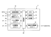
- FIG. 1 is a schematic view showing an embodiment of an exposure apparatus according to the present invention.
- This exposure apparatus forms a different exposure pattern for each of a plurality of exposure regions set on an object to be exposed while conveying the object to be exposed in one direction, and includes a conveying means 1, a light source 2, and coupling optics.
- the system 3 includes a mask stage 4, a shutter 5, an imaging unit 6, and a control unit 7.
- the transport means 1 places the object to be exposed 8 on the upper surface and transports it at a predetermined speed in the direction indicated by the arrow A.
- the air is ejected and sucked from the upper surface, and the air is ejected and sucked.
- both end edges of the exposed object 8 are held and conveyed by a conveying roller (not shown).
- the transport unit 1 includes a speed sensor that detects the moving speed of the object to be exposed 8 and a position sensor (not shown) that detects the position of the object to be exposed 8.
- the object 8 to be used here includes a first exposure region 9 in which a first exposure pattern group is to be formed and a second exposure pattern group in which a second exposure pattern group is to be formed.
- the exposure area 10 is preset at a predetermined interval in the transport direction (arrow A direction), and is, for example, a multicolored color filter substrate.
- a light source 2 is provided above the conveying means 1.
- the light source 2 emits ultraviolet light as the light source light 23, and is a xenon lamp, an ultrahigh pressure mercury lamp, a laser light source, or the like.
- a coupling optical system 3 is provided in front of the light source 2 in the light emission direction.
- the coupling optical system 3 converts the light source light 23 emitted from the light source 2 into parallel light and irradiates a mask pattern group of a photomask 11 described later, and includes optical components such as a photo integrator and a condenser lens. It is configured.
- a mask stage 4 is provided opposite to the upper surface of the transfer means 1. As shown in FIG. 3, the mask stage 4 includes first and second mask pattern groups 12 and 13 respectively corresponding to different types of first and second exposure pattern groups formed on the object 8 to be exposed.
- the peripheral edge of the photomask 11 formed by being arranged at a predetermined interval in the conveyance direction (arrow A direction) of the object to be exposed is held in the same direction as the conveyance direction of the object to be exposed 8 indicated by arrow A (arrow C direction). It is formed to be movable.
- a shutter 5 is provided between the coupling optical system 3 and the mask stage 4.
- the shutter 5 blocks and releases the light source light 23 applied to the photomask 11, and is in the same direction as the conveyance direction of the exposed object 8 indicated by an arrow A in synchronization with the movement of the exposed object 8 ( It is formed to be movable in the direction of arrow B).
- the imaging means 6 is provided so as to be able to image a position away from the exposure position by the photomask 11 by a predetermined distance in the direction opposite to the transport direction (arrow A direction).
- the imaging means 6 images the surface of the object to be exposed 8 and is a line in which a plurality of light receiving elements are arranged in a straight line in a direction substantially perpendicular to the transport direction in a plane parallel to the upper surface of the transport means 1. It is a camera.
- the image pickup means 6 is arranged so as to pick up an image of a position separated by a distance L in the direction opposite to the transport direction with reference to the exposure center position of the mask pattern group of the photomask 11.
- Control means 7 is provided by electrically connecting the transport means 1, the light source 2, the mask stage 4, the shutter 5, and the imaging means 6.
- the control means 7 appropriately controls the movement of the transport means 1, the mask stage 4 and the shutter 5.
- the image processing section 14, the memory 15, and the calculation section 16 are compared with each other.
- the image processing unit 14 processes the image of the surface of the object to be exposed 8 picked up by the image pickup means 6 and detects the position of each exposure region 9, 10 on the leading side in the transport direction.
- the memory 15 stores the dimension of each exposure area 9, 10 in the direction of arrow A, the distance L between the exposure center position by the photomask 11 and the imaging position by the imaging means 6, and the arithmetic unit described later.
- the calculation result in 16 is temporarily stored.
- the calculation unit 16 calculates the moving distance of the object to be exposed 8 based on the output of the position sensor of the transport unit 1.
- the comparator 17 compares the moving distance of the conveying means 1 calculated by the calculating unit 16 with each dimension read from the memory 15.
- the transport unit drive controller 18 controls the normal rotation drive and the reverse drive of the transport unit 1. Further, the mask stage drive controller 19 moves the mask stage 4 to switch from the first mask pattern group 12 of the photomask 11 to the second mask pattern group 13. Further, the shutter drive controller 20 moves the shutter 5 in synchronization with the conveyance speed of the object to be exposed 8. Furthermore, the light source drive controller 21 controls the turning on and off of the light source 2. And the control part 22 integrates and controls the whole apparatus so that each said component may drive appropriately.
- step S1 the mask stage 4 stops at the standby position, and the first mask pattern group 12 of the photomask 11 is selected. Further, the shutter 5 is stopped at the standby position and is in a state where the block of the light source light 23 is released.
- step S2 the conveying means 1 is controlled by the conveying means drive controller 18 to rotate forward, and starts an operation for conveying the object 8 to be exposed in the direction of arrow A at a predetermined speed.
- step S3 the image processing unit 14 processes the image of the surface of the object to be exposed 8 imaged by the imaging unit 6, and at the front edge of the first exposure region 9 in the arrow A direction, for example, the first The front edge of the reference pattern group composed of a plurality of reference patterns formed in advance in the exposure area 9 in the direction of arrow A is detected.
- step S ⁇ b> 4 the calculation unit 16 calculates the distance that the object 8 moves after detecting the front edge of the first exposure region 9 in the direction of arrow A based on the output of the position sensor of the transport unit 1. Then, the movement distance of the object to be exposed 8 calculated by the comparator 17 is compared with the distance L read from the memory 15. If they match and the determination is “YES” in step S4, the process proceeds to step S5.
- step S5 the light source drive controller 21 is activated to turn on the light source 2.
- the light source light 23 emitted from the light source 2 and converted into parallel light through the coupling optical system 3 irradiates the first mask pattern group 12 of the photomask 11, and the first exposure of the object 8 to be exposed is performed.
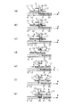
- a first exposure pattern 24 is exposed and formed in the region 9 (see FIG. 6A).
- step S ⁇ b> 6 the movement distance of the object to be exposed 8 is calculated by the calculation unit 16 based on the output of the position sensor of the transport unit 1, and the distance and the first exposure area 9 read from the memory 15 in the direction of arrow A. The dimensions are compared by the comparator 17, and it is determined whether or not the two match and the exposure for the first exposure region 9 is completed. Here, if the two match (see FIG. 6B) and the determination is “YES” in step S6, the process proceeds to step S7.
- step S7 the shutter drive controller 20 is activated to move the shutter 5 in the direction of arrow B (see FIG. 6C) in synchronization with the conveyance speed of the object 8 to be exposed.
- the movement of the shutter 5 is stopped, and at the same time, the transport unit 1 is also stopped (see FIG. 6D).
- step S8 the conveying means 1 is driven reversely by the conveying means drive controller 18, and the object 8 is moved in the opposite direction to the arrow A by the distance that the object 8 has moved while the shutter 5 is moving (in the direction opposite to the arrow A).
- the mask stage drive controller 19 is activated to move the mask stage 4 in the direction of arrow C, and the mask pattern group of the photomask 11 is switched from the first mask pattern group 12 to the second mask pattern group 13 (FIG. 6). (See (e)).
- step S9 the conveying means 1 is driven to rotate forward by the conveying means drive controller 18 to convey the object 8 again in the direction of arrow A, and the shutter drive controller 20 is activated to move the shutter 5 to the object 8 to be exposed. It is moved in the direction of arrow B in synchronization with the transport speed (see FIG. 6F). Then, when the blocking of the light source light 23 is completely cancelled, the movement of the shutter 5 is stopped, and the second mask pattern group 13 of the photomask 11 with respect to the second exposure region 10 of the object 8 to be exposed is second.
- the exposure pattern 25 is formed by exposure (see FIG. 6G).
- step S ⁇ b> 10 the movement distance of the object to be exposed 8 is calculated by the calculation unit 16 based on the output of the position sensor of the transport unit 1, and the distance and the second exposure area 10 read from the memory 15 in the direction of arrow A.
- the dimensions are compared by the comparator 17, and it is determined whether or not the two match and the exposure for the second exposure region 10 is completed.
- the two match and the determination is “YES”
- the exposure ends.
- the light source 2 is turned off under the control of the light source drive controller 21, and the drive of the transport unit 1 is stopped under the control of the transport unit drive controller 18.
- the conveying unit 1 is continuously driven.
- the present invention is not limited to this, and the number of exposure areas to be set may be three or more.
- the photomask 11 is provided with three or more mask pattern groups arranged side by side in the transport direction (arrow A direction) of the object 8 to be exposed.
- step S10 the process returns to step S7, and all exposures are performed. Steps S7 to S10 are repeatedly executed until the exposure for the area is completed.
- the shutter 5 a shutter in which a plurality of openings and light-shielding portions are alternately formed in the moving direction (arrow B direction) may be applied.
- the first and second mask pattern groups 12 and 13 are formed on the photomask 11 at a predetermined interval in the transport direction of the exposure object 8 .
- the first and second mask pattern groups 12 and 13 may be formed side by side in a direction substantially orthogonal to the transport direction of the object to be exposed.
- the mask stage 4 is moved in a direction substantially orthogonal to the conveyance direction of the object to be exposed 8 so that the first and second mask pattern groups 12 and 13 are switched.
- the photomask 11 is applied to a proximity exposure apparatus arranged close to and opposite to the object 8 to be exposed.
- the present invention is not limited to this, and the mask pattern of the photomask 11 is used. You may apply to the projection exposure apparatus which projects and exposes a group on the to-be-exposed body 8. FIG. In this case, the moving direction of the shutter 5 is opposite to the conveying direction of the object 8 to be exposed.
Landscapes
- Physics & Mathematics (AREA)
- General Physics & Mathematics (AREA)
- Exposure And Positioning Against Photoresist Photosensitive Materials (AREA)
- Exposure Of Semiconductors, Excluding Electron Or Ion Beam Exposure (AREA)
Abstract
Description
先ず、ステップS1においては、マスクステージ4は、待機位置に停止してフォトマスク11の第1のマスクパターン群12が選択されている。また、シャッタ5は、待機位置に停止して光源光23の遮断が解除された状態にある。
4…マスクステージ
5…シャッタ
8…被露光体
9…第1の露光領域
10…第2の露光領域
11…フォトマスク
12…第1のマスクパターン群
13…第2のマスクパターン群
23…光源光
24…第1の露光パターン
25…第2の露光パターン
Claims (6)
- 被露光体を一方向に搬送しながら該被露光体の搬送方向に所定間隔で設定された複数の露光領域毎に異なる露光パターンを形成する露光方法であって、
前記各露光パターンに対応する複数種のマスクパターン群を前記被露光体の搬送方向に所定間隔で並べて形成したフォトマスクの一のマスクパターン群を使用して行う前記被露光体の一の露光領域に対する露光が終了すると、シャッタを前記被露光体の搬送速度に同期して移動して光源光を遮断する段階と、
前記被露光体が前記シャッタの移動中に移動した距離だけ前記被露光体を前記搬送方向と反対方向に戻すと共に、前記フォトマスクを移動して前記一のマスクパターン群から別のマスクパターン群に切り替える段階と、
前記フォトマスクの前記一のマスクパターン群から別のマスクパターン群への切り替えが終了すると、前記被露光体の前記搬送方向への搬送を再開するのと同時に、前記シャッタを前記被露光体の搬送速度に同期して移動して光源光の遮断を解除し、次の露光領域に対する露光を実行する段階と、
を行うことを特徴とする露光方法。 - 前記シャッタは、前記被露光体の搬送方向に移動されることを特徴とする請求項1記載の露光方法。
- 前記シャッタは、前記被露光体の搬送方向に複数の遮光部と開口部とを交互に配置して備えたことを特徴とする請求項1又は2記載の露光方法。
- 被露光体を一方向に搬送しながら該被露光体の搬送方向に所定間隔で設定された複数の露光領域毎に異なる露光パターンを形成する露光装置であって、
前記被露光体を所定速度で搬送する搬送手段と、
前記被露光体の移動と同期して移動可能に形成され、光源光を遮断及び遮断解除するシャッタと、
前記搬送手段の上面に対向して配設され、前記各露光パターンに対応する複数種のマスクパターン群を形成したフォトマスクを保持すると共に、移動して前記複数種のマスクパターン群の切り替えをするマスクステージと、を備え、
前記フォトマスクの一のマスクパターン群を使用して行う、前記被露光体の一の露光領域に対する露光が終了すると、前記シャッタを移動して光源光を遮断し、
前記被露光体が前記シャッタの移動中に移動した距離だけ前記搬送手段により前記被露光体を前記搬送方向と反対方向に戻すと共に、前記マスクステージを移動して前記フォトマスクの一のマスクパターン群から別のマスクパターン群に切り替え、
前記被露光体の前記搬送方向への搬送を再開するのと同時に、前記シャッタを移動して光源光の遮断を解除し、次の露光領域に対する露光を実行する、
ことを特徴とする露光装置。 - 前記シャッタは、前記被露光体の搬送方向に移動されることを特徴とする請求項4記載の露光装置。
- 前記シャッタは、前記被露光体の搬送方向に複数の遮光部と開口部とを交互に配置して備えたことを特徴とする請求項4又は5記載の露光装置。
Priority Applications (3)
| Application Number | Priority Date | Filing Date | Title |
|---|---|---|---|
| KR1020117024326A KR101688128B1 (ko) | 2009-04-03 | 2010-03-17 | 노광 방법 및 노광 장치 |
| CN201080014236.0A CN102365589B (zh) | 2009-04-03 | 2010-03-17 | 曝光方法及曝光装置 |
| US13/251,850 US8497979B2 (en) | 2009-04-03 | 2011-10-03 | Exposure method and exposure apparatus |
Applications Claiming Priority (2)
| Application Number | Priority Date | Filing Date | Title |
|---|---|---|---|
| JP2009-090617 | 2009-04-03 | ||
| JP2009090617A JP5258051B2 (ja) | 2009-04-03 | 2009-04-03 | 露光方法及び露光装置 |
Related Child Applications (1)
| Application Number | Title | Priority Date | Filing Date |
|---|---|---|---|
| US13/251,850 Continuation US8497979B2 (en) | 2009-04-03 | 2011-10-03 | Exposure method and exposure apparatus |
Publications (1)
| Publication Number | Publication Date |
|---|---|
| WO2010113644A1 true WO2010113644A1 (ja) | 2010-10-07 |
Family
ID=42827944
Family Applications (1)
| Application Number | Title | Priority Date | Filing Date |
|---|---|---|---|
| PCT/JP2010/054565 Ceased WO2010113644A1 (ja) | 2009-04-03 | 2010-03-17 | 露光方法及び露光装置 |
Country Status (6)
| Country | Link |
|---|---|
| US (1) | US8497979B2 (ja) |
| JP (1) | JP5258051B2 (ja) |
| KR (1) | KR101688128B1 (ja) |
| CN (1) | CN102365589B (ja) |
| TW (1) | TWI490658B (ja) |
| WO (1) | WO2010113644A1 (ja) |
Families Citing this family (2)
| Publication number | Priority date | Publication date | Assignee | Title |
|---|---|---|---|---|
| JP5354803B2 (ja) | 2010-06-28 | 2013-11-27 | 株式会社ブイ・テクノロジー | 露光装置 |
| JP6762640B1 (ja) * | 2020-07-06 | 2020-09-30 | 株式会社 ベアック | 露光装置 |
Citations (4)
| Publication number | Priority date | Publication date | Assignee | Title |
|---|---|---|---|---|
| JPH1152583A (ja) * | 1997-08-08 | 1999-02-26 | Hitachi Electron Eng Co Ltd | プロキシミティ露光装置 |
| JP2002099097A (ja) * | 2000-09-25 | 2002-04-05 | Nikon Corp | 走査露光方法および走査型露光装置 |
| JP2007281317A (ja) * | 2006-04-11 | 2007-10-25 | V Technology Co Ltd | 露光装置 |
| JP2009058666A (ja) * | 2007-08-30 | 2009-03-19 | V Technology Co Ltd | 露光装置 |
Family Cites Families (14)
| Publication number | Priority date | Publication date | Assignee | Title |
|---|---|---|---|---|
| US6078381A (en) * | 1993-02-01 | 2000-06-20 | Nikon Corporation | Exposure method and apparatus |
| JP3209294B2 (ja) * | 1993-02-01 | 2001-09-17 | 株式会社ニコン | 露光装置 |
| JP3377053B2 (ja) * | 1993-09-21 | 2003-02-17 | 株式会社ニコン | 露光装置 |
| DE69434080T2 (de) * | 1993-06-11 | 2005-10-20 | Nikon Corp. | Abtastbelichtungsvorrichtung |
| JP3451604B2 (ja) * | 1994-06-17 | 2003-09-29 | 株式会社ニコン | 走査型露光装置 |
| JPH11237744A (ja) * | 1997-12-18 | 1999-08-31 | Sanee Giken Kk | 露光装置および露光方法 |
| JP3360662B2 (ja) * | 1999-10-05 | 2002-12-24 | 日本電気株式会社 | 電子線ビーム描画方法および電子線ビーム描画用マスク |
| JP4581262B2 (ja) * | 2000-02-18 | 2010-11-17 | 株式会社ニコン | 露光装置及び露光方法 |
| US7671970B2 (en) * | 2005-07-13 | 2010-03-02 | Asml Netherlands B.V. | Stage apparatus with two patterning devices, lithographic apparatus and device manufacturing method skipping an exposure field pitch |
| JP5382899B2 (ja) * | 2005-10-25 | 2014-01-08 | 株式会社ブイ・テクノロジー | 露光装置 |
| JP2007193154A (ja) * | 2006-01-20 | 2007-08-02 | Hitachi High-Technologies Corp | 露光装置、露光方法、及び表示用パネル基板の製造方法 |
| US8023103B2 (en) * | 2006-03-03 | 2011-09-20 | Nikon Corporation | Exposure apparatus, exposure method, and method for producing device |
| EP1993120A1 (en) * | 2006-03-03 | 2008-11-19 | Nikon Corporation | Exposure method and apparatus, and device manufacturing method |
| JP5083517B2 (ja) * | 2007-06-18 | 2012-11-28 | 凸版印刷株式会社 | 異種パターンの露光方法 |
-
2009
- 2009-04-03 JP JP2009090617A patent/JP5258051B2/ja not_active Expired - Fee Related
-
2010
- 2010-03-17 KR KR1020117024326A patent/KR101688128B1/ko not_active Expired - Fee Related
- 2010-03-17 CN CN201080014236.0A patent/CN102365589B/zh not_active Expired - Fee Related
- 2010-03-17 WO PCT/JP2010/054565 patent/WO2010113644A1/ja not_active Ceased
- 2010-04-02 TW TW099110265A patent/TWI490658B/zh not_active IP Right Cessation
-
2011
- 2011-10-03 US US13/251,850 patent/US8497979B2/en not_active Expired - Fee Related
Patent Citations (4)
| Publication number | Priority date | Publication date | Assignee | Title |
|---|---|---|---|---|
| JPH1152583A (ja) * | 1997-08-08 | 1999-02-26 | Hitachi Electron Eng Co Ltd | プロキシミティ露光装置 |
| JP2002099097A (ja) * | 2000-09-25 | 2002-04-05 | Nikon Corp | 走査露光方法および走査型露光装置 |
| JP2007281317A (ja) * | 2006-04-11 | 2007-10-25 | V Technology Co Ltd | 露光装置 |
| JP2009058666A (ja) * | 2007-08-30 | 2009-03-19 | V Technology Co Ltd | 露光装置 |
Also Published As
| Publication number | Publication date |
|---|---|
| KR101688128B1 (ko) | 2016-12-20 |
| US8497979B2 (en) | 2013-07-30 |
| JP5258051B2 (ja) | 2013-08-07 |
| JP2010243679A (ja) | 2010-10-28 |
| CN102365589B (zh) | 2014-03-26 |
| TW201107892A (en) | 2011-03-01 |
| CN102365589A (zh) | 2012-02-29 |
| TWI490658B (zh) | 2015-07-01 |
| KR20120007000A (ko) | 2012-01-19 |
| US20120113403A1 (en) | 2012-05-10 |
Similar Documents
| Publication | Publication Date | Title |
|---|---|---|
| JP5458372B2 (ja) | 露光方法及び露光装置 | |
| CN101460897B (zh) | 曝光方法以及曝光装置 | |
| JP2007121344A (ja) | 露光装置 | |
| JP2011008180A (ja) | アライメント方法、アライメント装置及び露光装置 | |
| JP5235061B2 (ja) | 露光装置 | |
| US9030646B2 (en) | Exposure apparatus and photomask used therein | |
| JP5258051B2 (ja) | 露光方法及び露光装置 | |
| JP5098041B2 (ja) | 露光方法 | |
| JP5261847B2 (ja) | アライメント方法、アライメント装置及び露光装置 | |
| JP5282941B2 (ja) | 近接露光装置 | |
| TW202043845A (zh) | 直接描繪式曝光裝置 | |
| TWI481971B (zh) | 曝光方法及曝光裝置 | |
| TWI497225B (zh) | 曝光方法及曝光裝置 | |
| JP2008076709A (ja) | 露光装置 | |
| JP4309874B2 (ja) | 露光装置 | |
| JP4773160B2 (ja) | 露光装置 | |
| JP4773158B2 (ja) | 露光装置 | |
| JP2010085830A (ja) | カラーフィルタの製造装置 |
Legal Events
| Date | Code | Title | Description |
|---|---|---|---|
| WWE | Wipo information: entry into national phase |
Ref document number: 201080014236.0 Country of ref document: CN |
|
| 121 | Ep: the epo has been informed by wipo that ep was designated in this application |
Ref document number: 10758420 Country of ref document: EP Kind code of ref document: A1 |
|
| NENP | Non-entry into the national phase |
Ref country code: DE |
|
| ENP | Entry into the national phase |
Ref document number: 20117024326 Country of ref document: KR Kind code of ref document: A |
|
| 122 | Ep: pct application non-entry in european phase |
Ref document number: 10758420 Country of ref document: EP Kind code of ref document: A1 |