WO2010110330A1 - Équipement de production d'énergie éolienne offshore et son procédé de construction - Google Patents
Équipement de production d'énergie éolienne offshore et son procédé de construction Download PDFInfo
- Publication number
- WO2010110330A1 WO2010110330A1 PCT/JP2010/055107 JP2010055107W WO2010110330A1 WO 2010110330 A1 WO2010110330 A1 WO 2010110330A1 JP 2010055107 W JP2010055107 W JP 2010055107W WO 2010110330 A1 WO2010110330 A1 WO 2010110330A1
- Authority
- WO
- WIPO (PCT)
- Prior art keywords
- tower
- floating body
- wind power
- offshore wind
- floating
- Prior art date
Links
Images


Classifications
-
- B—PERFORMING OPERATIONS; TRANSPORTING
- B63—SHIPS OR OTHER WATERBORNE VESSELS; RELATED EQUIPMENT
- B63B—SHIPS OR OTHER WATERBORNE VESSELS; EQUIPMENT FOR SHIPPING
- B63B35/00—Vessels or similar floating structures specially adapted for specific purposes and not otherwise provided for
- B63B35/44—Floating buildings, stores, drilling platforms, or workshops, e.g. carrying water-oil separating devices
-
- B—PERFORMING OPERATIONS; TRANSPORTING
- B63—SHIPS OR OTHER WATERBORNE VESSELS; RELATED EQUIPMENT
- B63B—SHIPS OR OTHER WATERBORNE VESSELS; EQUIPMENT FOR SHIPPING
- B63B1/00—Hydrodynamic or hydrostatic features of hulls or of hydrofoils
- B63B1/02—Hydrodynamic or hydrostatic features of hulls or of hydrofoils deriving lift mainly from water displacement
- B63B1/04—Hydrodynamic or hydrostatic features of hulls or of hydrofoils deriving lift mainly from water displacement with single hull
- B63B1/048—Hydrodynamic or hydrostatic features of hulls or of hydrofoils deriving lift mainly from water displacement with single hull with hull extending principally vertically
-
- B—PERFORMING OPERATIONS; TRANSPORTING
- B63—SHIPS OR OTHER WATERBORNE VESSELS; RELATED EQUIPMENT
- B63B—SHIPS OR OTHER WATERBORNE VESSELS; EQUIPMENT FOR SHIPPING
- B63B21/00—Tying-up; Shifting, towing, or pushing equipment; Anchoring
- B63B21/50—Anchoring arrangements or methods for special vessels, e.g. for floating drilling platforms or dredgers
-
- B—PERFORMING OPERATIONS; TRANSPORTING
- B63—SHIPS OR OTHER WATERBORNE VESSELS; RELATED EQUIPMENT
- B63B—SHIPS OR OTHER WATERBORNE VESSELS; EQUIPMENT FOR SHIPPING
- B63B5/00—Hulls characterised by their construction of non-metallic material
-
- B—PERFORMING OPERATIONS; TRANSPORTING
- B63—SHIPS OR OTHER WATERBORNE VESSELS; RELATED EQUIPMENT
- B63B—SHIPS OR OTHER WATERBORNE VESSELS; EQUIPMENT FOR SHIPPING
- B63B77/00—Transporting or installing offshore structures on site using buoyancy forces, e.g. using semi-submersible barges, ballasting the structure or transporting of oil-and-gas platforms
- B63B77/10—Transporting or installing offshore structures on site using buoyancy forces, e.g. using semi-submersible barges, ballasting the structure or transporting of oil-and-gas platforms specially adapted for electric power plants, e.g. wind turbines or tidal turbine generators
-
- F—MECHANICAL ENGINEERING; LIGHTING; HEATING; WEAPONS; BLASTING
- F03—MACHINES OR ENGINES FOR LIQUIDS; WIND, SPRING, OR WEIGHT MOTORS; PRODUCING MECHANICAL POWER OR A REACTIVE PROPULSIVE THRUST, NOT OTHERWISE PROVIDED FOR
- F03D—WIND MOTORS
- F03D13/00—Assembly, mounting or commissioning of wind motors; Arrangements specially adapted for transporting wind motor components
- F03D13/10—Assembly of wind motors; Arrangements for erecting wind motors
-
- F—MECHANICAL ENGINEERING; LIGHTING; HEATING; WEAPONS; BLASTING
- F03—MACHINES OR ENGINES FOR LIQUIDS; WIND, SPRING, OR WEIGHT MOTORS; PRODUCING MECHANICAL POWER OR A REACTIVE PROPULSIVE THRUST, NOT OTHERWISE PROVIDED FOR
- F03D—WIND MOTORS
- F03D13/00—Assembly, mounting or commissioning of wind motors; Arrangements specially adapted for transporting wind motor components
- F03D13/20—Arrangements for mounting or supporting wind motors; Masts or towers for wind motors
- F03D13/25—Arrangements for mounting or supporting wind motors; Masts or towers for wind motors specially adapted for offshore installation
-
- F—MECHANICAL ENGINEERING; LIGHTING; HEATING; WEAPONS; BLASTING
- F03—MACHINES OR ENGINES FOR LIQUIDS; WIND, SPRING, OR WEIGHT MOTORS; PRODUCING MECHANICAL POWER OR A REACTIVE PROPULSIVE THRUST, NOT OTHERWISE PROVIDED FOR
- F03D—WIND MOTORS
- F03D13/00—Assembly, mounting or commissioning of wind motors; Arrangements specially adapted for transporting wind motor components
- F03D13/40—Arrangements or methods specially adapted for transporting wind motor components
-
- B—PERFORMING OPERATIONS; TRANSPORTING
- B63—SHIPS OR OTHER WATERBORNE VESSELS; RELATED EQUIPMENT
- B63B—SHIPS OR OTHER WATERBORNE VESSELS; EQUIPMENT FOR SHIPPING
- B63B1/00—Hydrodynamic or hydrostatic features of hulls or of hydrofoils
- B63B1/02—Hydrodynamic or hydrostatic features of hulls or of hydrofoils deriving lift mainly from water displacement
- B63B1/04—Hydrodynamic or hydrostatic features of hulls or of hydrofoils deriving lift mainly from water displacement with single hull
- B63B2001/044—Hydrodynamic or hydrostatic features of hulls or of hydrofoils deriving lift mainly from water displacement with single hull with a small waterline area compared to total displacement, e.g. of semi-submersible type
-
- B—PERFORMING OPERATIONS; TRANSPORTING
- B63—SHIPS OR OTHER WATERBORNE VESSELS; RELATED EQUIPMENT
- B63B—SHIPS OR OTHER WATERBORNE VESSELS; EQUIPMENT FOR SHIPPING
- B63B35/00—Vessels or similar floating structures specially adapted for specific purposes and not otherwise provided for
- B63B35/44—Floating buildings, stores, drilling platforms, or workshops, e.g. carrying water-oil separating devices
- B63B2035/442—Spar-type semi-submersible structures, i.e. shaped as single slender, e.g. substantially cylindrical or trussed vertical bodies
-
- B—PERFORMING OPERATIONS; TRANSPORTING
- B63—SHIPS OR OTHER WATERBORNE VESSELS; RELATED EQUIPMENT
- B63B—SHIPS OR OTHER WATERBORNE VESSELS; EQUIPMENT FOR SHIPPING
- B63B35/00—Vessels or similar floating structures specially adapted for specific purposes and not otherwise provided for
- B63B35/44—Floating buildings, stores, drilling platforms, or workshops, e.g. carrying water-oil separating devices
- B63B2035/4433—Floating structures carrying electric power plants
- B63B2035/446—Floating structures carrying electric power plants for converting wind energy into electric energy
-
- F—MECHANICAL ENGINEERING; LIGHTING; HEATING; WEAPONS; BLASTING
- F05—INDEXING SCHEMES RELATING TO ENGINES OR PUMPS IN VARIOUS SUBCLASSES OF CLASSES F01-F04
- F05B—INDEXING SCHEME RELATING TO WIND, SPRING, WEIGHT, INERTIA OR LIKE MOTORS, TO MACHINES OR ENGINES FOR LIQUIDS COVERED BY SUBCLASSES F03B, F03D AND F03G
- F05B2240/00—Components
- F05B2240/90—Mounting on supporting structures or systems
- F05B2240/91—Mounting on supporting structures or systems on a stationary structure
- F05B2240/915—Mounting on supporting structures or systems on a stationary structure which is vertically adjustable
- F05B2240/9151—Mounting on supporting structures or systems on a stationary structure which is vertically adjustable telescopically
-
- F—MECHANICAL ENGINEERING; LIGHTING; HEATING; WEAPONS; BLASTING
- F05—INDEXING SCHEMES RELATING TO ENGINES OR PUMPS IN VARIOUS SUBCLASSES OF CLASSES F01-F04
- F05B—INDEXING SCHEME RELATING TO WIND, SPRING, WEIGHT, INERTIA OR LIKE MOTORS, TO MACHINES OR ENGINES FOR LIQUIDS COVERED BY SUBCLASSES F03B, F03D AND F03G
- F05B2240/00—Components
- F05B2240/90—Mounting on supporting structures or systems
- F05B2240/91—Mounting on supporting structures or systems on a stationary structure
- F05B2240/916—Mounting on supporting structures or systems on a stationary structure with provision for hoisting onto the structure
-
- F—MECHANICAL ENGINEERING; LIGHTING; HEATING; WEAPONS; BLASTING
- F05—INDEXING SCHEMES RELATING TO ENGINES OR PUMPS IN VARIOUS SUBCLASSES OF CLASSES F01-F04
- F05B—INDEXING SCHEME RELATING TO WIND, SPRING, WEIGHT, INERTIA OR LIKE MOTORS, TO MACHINES OR ENGINES FOR LIQUIDS COVERED BY SUBCLASSES F03B, F03D AND F03G
- F05B2240/00—Components
- F05B2240/90—Mounting on supporting structures or systems
- F05B2240/93—Mounting on supporting structures or systems on a structure floating on a liquid surface
-
- Y—GENERAL TAGGING OF NEW TECHNOLOGICAL DEVELOPMENTS; GENERAL TAGGING OF CROSS-SECTIONAL TECHNOLOGIES SPANNING OVER SEVERAL SECTIONS OF THE IPC; TECHNICAL SUBJECTS COVERED BY FORMER USPC CROSS-REFERENCE ART COLLECTIONS [XRACs] AND DIGESTS
- Y02—TECHNOLOGIES OR APPLICATIONS FOR MITIGATION OR ADAPTATION AGAINST CLIMATE CHANGE
- Y02E—REDUCTION OF GREENHOUSE GAS [GHG] EMISSIONS, RELATED TO ENERGY GENERATION, TRANSMISSION OR DISTRIBUTION
- Y02E10/00—Energy generation through renewable energy sources
- Y02E10/70—Wind energy
- Y02E10/72—Wind turbines with rotation axis in wind direction
-
- Y—GENERAL TAGGING OF NEW TECHNOLOGICAL DEVELOPMENTS; GENERAL TAGGING OF CROSS-SECTIONAL TECHNOLOGIES SPANNING OVER SEVERAL SECTIONS OF THE IPC; TECHNICAL SUBJECTS COVERED BY FORMER USPC CROSS-REFERENCE ART COLLECTIONS [XRACs] AND DIGESTS
- Y02—TECHNOLOGIES OR APPLICATIONS FOR MITIGATION OR ADAPTATION AGAINST CLIMATE CHANGE
- Y02E—REDUCTION OF GREENHOUSE GAS [GHG] EMISSIONS, RELATED TO ENERGY GENERATION, TRANSMISSION OR DISTRIBUTION
- Y02E10/00—Energy generation through renewable energy sources
- Y02E10/70—Wind energy
- Y02E10/727—Offshore wind turbines
Definitions
- the present invention relates to a spar-type offshore wind power generation facility installed on a relatively deep sea and a construction method thereof.
- Patent Document 1 a wind power generator is proposed in which a floating body that floats on a plane triangular water is formed by combining hollow square columnar structures, and a wind turbine for power generation is provided thereon. This floating body floats on the surface of the water and is called “pontoon type”.
- Patent Document 2 a plurality of floating body portions on which articles are placed, and a longitudinal shape that connects each floating body portion to an outer end extending in a horizontal radial direction by connecting an inner end to a predetermined center.
- a floating body structure including a connecting portion made of a rigid body and a tension portion that generates a tensile force between the floating body portions.
- Patent Document 3 a plurality of floating body portions floating in water, a connecting portion made of a rigid body that connects the floating body portions in an annular shape, mooring means for anchoring an annular substantially central portion on the water bottom, and the position of the floating body portion
- a position detecting means for detecting a tidal current a tidal current detecting means for detecting a tidal current
- a floating body structure including a position control unit that varies the position of each floating body centering around an annular substantially central portion.
- the floating structure according to Patent Documents 2 and 3 is called a “semi-sub type” because it floats in a state where the floating body is submerged below the water surface.
- Patent Document 4 a lower floating body in which upper and lower lids and a cylindrical precast concrete block continuously installed between them are integrally joined with a PC steel material, and the lower floating body with a PC steel material.
- the upper float is composed of a precast concrete block having a smaller diameter than the precast concrete block and the upper lid, and a plurality of ballast tanks are formed inside the lower float by a partition wall inside the upper float.
- This patent document 4 is called a “spar type” because it floats in a standing state like a fishing float.
- JP 2001-165032 A JP 2007-160965 A JP 2007-331414 A JP 2009-18671 A
- the spar type floating body can attach only one wind turbine to one floating body, but has the advantages that it is more economical than the other pontoon type and semi-sub type, and has excellent floating body stability.
- the construction of the wind power generation facility using the spar type floating body is assembled in an onshore production yard, then towed to the ocean, carried to the offshore installation site, and floated in a standing state by throwing in ballast water.
- the height of the tower is as high as 50 to 80 m, the installation of nacelle and windmill blades is a high place work and there is a high risk, and these maintenance work is also a high place work.
- the main problem of the present invention is that the offshore wind power generation equipment has advantages such as easy and safe installation on the sea, easy maintenance, and ensuring stability in strong winds or waves. It is to provide the construction method.
- the present invention includes a floating body, a deck installed above the floating body, a mooring line connected to the deck, and a tower standing on the deck.
- an offshore wind power generation facility consisting of a nacelle and a plurality of windmill blades installed at the top of this tower,
- the floating body includes a lower concrete floating body structure in which a plurality of precast cylindrical bodies made of concrete are stacked in the height direction, and each precast cylindrical body is fastened and integrated with PC steel, and the lower concrete floating body
- a spar type floating structure having a bottomed hollow part with an open upper end, and at least during construction, the tower is provided on the deck.
- an offshore wind power generation facility that can be moved up and down by a tower lifting and lowering facility and can be accommodated inside the floating body.
- the lower concrete floating structure in which the floating body is made of a plurality of precast cylindrical bodies made of concrete and stacked in the height direction, and each precast cylindrical body is fastened and integrated with PC steel. And a spar type floating body structure having a bottomed hollow portion having an upper end opened, and an upper steel floating body structure portion continuously provided on the upper side of the lower concrete floating body structure portion.
- the tower is towed in a state of being accommodated in the floating body, and the floating body is erected in an upright state by throwing in the ballast.
- the nacelle installed in the state of being pulled up to the height position, the wind turbine blades are installed, and after the installation of all members is completed, the tower is lifted and fixed to the normal height position.
- the nacelle and windmill blade can be attached in the lowered state, and the work at a high place is reduced, enabling safe construction.
- the work can be safely performed by lowering the tower during maintenance after service, and the stability is increased and the risk of damage is reduced by lowering the tower even during strong winds or waves.
- the center of gravity can be lowered by adopting a floating structure consisting of the lower concrete floating structure and the upper steel floating structure, the stability of the floating structure is increased and the length of the floating structure is reduced. It becomes possible to do. Since the portion that protrudes on the sea is made of steel, it is advantageous in that it is advantageous for a ship collision.
- the offshore wind power generation facility according to claim 1 is provided, wherein the upper steel floating structure has a variable cross-sectional shape in which the outer diameter dimension is gradually reduced in the height direction. .
- the invention described in claim 2 is such that the upper steel floating structure has a variable cross-sectional shape whose outer diameter is gradually reduced in the height direction. Accordingly, the center of gravity is lowered and stability against strong winds and waves is increased, and the upper side is relatively small in diameter so that it is less likely to be affected by waves in normal times.
- the present invention according to claim 3 is a construction method for installing the offshore wind power generation facility according to any of claims 1 and 2 on the ocean, A first step of floating sideways on the sea with the tower housed inside the floating body and towing to the offshore installation location; A second procedure for raising the floating body in an upright state by inserting ballast at an offshore installation location; A third step of installing the nacelle and the wind turbine blade in a state where the tower is raised to an arbitrary height position by the tower lifting equipment; A construction method of an offshore wind power generation facility is provided, which includes a fourth step of lifting and fixing the tower to a normal height position.
- the nacelle and the wind turbine blade can be attached in a state where the tower is lowered, so that the work at a high place is reduced and the construction can be performed safely.
- offshore wind power generation has advantages such as easy and safe installation on the ocean, easy maintenance, and stability during strong winds or waves. It can be equipment.
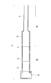
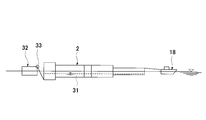
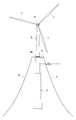
- FIG. 1 is a schematic view of an offshore wind power generation facility 1 according to the present invention.
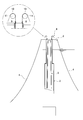
- 2 is a longitudinal sectional view of a floating body 2.
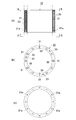
- FIG. The precast cylindrical body 12 (13) is shown, (A) is a longitudinal sectional view, (B) is a plan view (a view taken along the line B-B), and (C) is a bottom view (a view taken along the line C-C).
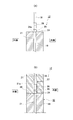
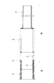
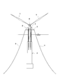
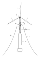
- FIG. 4 is a schematic diagram (A) and (B) of the tight connection between precast cylindrical bodies 12 (13). It is a longitudinal cross-sectional view which shows an upper steel floating body structure part. It is construction procedure figure (the 1) of offshore wind power generation equipment. It is construction procedure figure (the 2) of offshore wind power generation equipment. It is construction procedure figure (the 3) of offshore wind power generation equipment.
- the offshore wind turbine power generation facility 1 includes a floating body 2, a deck 3 installed on the top of the floating body 2, mooring lines 4, 4... Connected to the deck 3, and the deck 3.
- the tower 5 is provided on the top of the tower 5, and the nacelle 6 and the plurality of windmill blades 7, 7.
- the floating body 2 is formed by stacking a plurality of precast cylindrical bodies 12 to 13 made of concrete in the height direction, and the precast cylindrical bodies 12 to 13 are tightly joined by a PC steel material.
- the lower concrete floating structure 2A and the upper steel floating structure 2B connected to the upper side of the lower concrete floating structure 2A, and the bottomed hollow part having an open upper end
- the tower 5 can be moved up and down by a tower lifting device provided on the deck 3 at the time of construction and can be accommodated inside the floating body 2.
- the flood water L of the floating body 2 is set to approximately 60 m or more in the case of 2 MW class power generation equipment.
- the floating body 2 includes a bottomed cylindrical ballast portion 10, a lower concrete floating structure portion 2 ⁇ / b> A connected to the upper surface of the ballast portion 10, and the lower concrete floating structure portion. It consists of the upper steel floating body structure part 2B provided continuously on the upper side of 2A.
- the ballast portion 10 and the lower concrete floating structure portion 2A are all concrete precast members.
- a synthetic precast member 13 is interposed at the boundary between the lower concrete floating structure 2A and the upper steel floating structure 2B, and both are joined.
- the upper steel floating body structure portion 2B has a variable cross-sectional shape in which the outer diameter dimension is gradually reduced in the height direction. In the illustrated example, it has a two-stage variable cross-sectional shape.
- the lower concrete floating body structure portion 2A is composed of a precast cylindrical body 12 made of concrete and a lower half portion of the synthetic precast member 13.
- the precast cylindrical body 12 is a circular cylindrical precast member having the same cross section in the axial direction, and each is manufactured using the same mold or by centrifugal molding. The manufactured hollow precast member is used.
- sheaths 21, 21... For inserting the PC steel bars 19 are embedded in the wall surface at appropriate intervals in the circumferential direction.
- a sheath widened portion 21a is formed at the lower end of the sheaths 21, 21... So that a coupler for connecting the PC steel bars 19 can be inserted, and a fixing anchor plate is fitted on the upper portion.
- a box opening portion 22 is provided for installation.
- a plurality of suspension fittings 23 are provided on the upper surface.
- the precast cylindrical bodies 12 are fastened by inserting the PC steel rods 19, 19... Extended upward from the lower-stage precast cylindrical body 12 into the sheaths 21, 21.
- the anchor plate 24 is fitted into the box opening portion 22, and tension is introduced into the PC steel bar 19 by the nut member 25 to achieve integration.
- a grout material is injected into the sheath 21 from the grout injection hole 27.
- the hole 24a formed in the anchor plate 24 is a grout injection confirmation hole, and the filling of the grout material is completed when the grout material is discharged from the confirmation hole.
- the synthetic precast member 13 has a composite structure of a concrete precast tubular body 16 and a steel tubular body 17. These are manufactured integrally.
- the precast tubular body 16 has an outer diameter dimension obtained by reducing the thickness of the steel tubular body 17, and the lower half portion of the steel tubular body 17 is fitted on the outer periphery.
- the upper end surface of the precast cylindrical body 16 is a fastening surface of the PC steel rod 19.
- the upper steel floating structure 2B is composed of an upper half portion of the synthetic precast member 13 and steel tubular bodies 14 and 15.
- the lower-stage steel tubular body 14 has the same outer diameter as that of the synthetic precast member 13 and is connected to the synthetic precast member 13 by bolts, welding, or the like (in the illustrated example, bolt fastening).
- the upper-stage steel tubular body 15 has an outer diameter smaller than that of the lower-stage steel tubular body 14 and has a variable cross-sectional shape. They are connected by welding or the like (in the illustrated example, bolt fastening).
- the upper end of the upper steel tubular body 15 is left open, the boundary between the upper steel tubular body 15 and the lower steel tubular body 14 and the lower steel tubular body. A space is not partitioned at the boundary between 14 and the steel tubular body 17, and a hollow portion for accommodating the tower 5 is formed inside the floating body 2.
- the tower 5 is made of steel, concrete, or PRC (prestressed reinforced concrete), but is preferably made of steel so as to reduce the total weight.
- the nacelle 6 is a device equipped with a generator that converts the rotation of the windmill into electricity, a controller that can automatically change the angle of the blade, and the like.
- the deck 3 is installed on the floating body 2, one end of the mooring line 4 is tied to the deck 3, and the other end is set on the seabed.
- the floating body 2 is stabilized by being tied to the anchor.
- the tower lifting / lowering equipment 8 is installed on the deck 3 and the tower 5 is pulled up.
- the tower lifting / lowering equipment 8 has center hole jacks 9, 9,... Arranged at predetermined intervals around the base of the tower 5 as shown in the figure, and one end of the PC steel wire 10 is wound around a sheave 11. Then, the center hole jack 9 is tightly connected to the lower end of the tower 5, and the tower 5 can be lowered and raised by the expansion / contraction operation of the center hole jack 9.
- the nacelle 6 is installed and the two wind turbine blades 7 and 7 are installed in a state where the tower 5 is pulled up to an arbitrary height position by the tower elevating equipment 8. Thereafter, as shown in FIG. 11, the tower 5 is slightly lifted and the remaining wind turbine blades 7 are attached.
Abstract
L'invention concerne un équipement de production d'énergie éolienne offshore qui, tout en permettant de réaliser une installation offshore simple et sûre, met en œuvre des avantages tels qu'un entretien simple. L'invention est telle qu'elle se compose d'un corps flottant (2), d'un ponton (3) disposé sur une partie supérieure dudit corps flottant (2), de câbles d'amarrage (4, 4,...) raccordés audit ponton (3), d'une tour (5) érigée sur le ponton susmentionné (3), d'une nacelle (6) et de plusieurs lames d'éolienne (7, 7,...) installées sur une partie de sommet de la tour (5). Un corps principal susmentionné (2) se compose d'une part d'une partie de structure flottante (2A) en béton d'un côté inférieur superposant, dans le sens de la hauteur, plusieurs étages de corps cylindriques (12) prémoulés en béton, et permettant la fixation et l'intégration de chaque corps cylindrique (12) prémoulé, à l'aide d'un matériau d'acier précontraint PC (19); d'autre part d'une partie de structure flottante (2B) en acier d'un côté supérieur, raccordée à un côté supérieur de ladite partie de structure flottante (2A) en béton du côté inférieur; et sert de structure flottante de type SPAR possédant une partie creuse avec un fond, dans laquelle une partie d'extrémité supérieure est ouverte. La tour susmentionnée (5), peut, au moins lors de la construction, s'élever et s'abaisser grâce à un équipement d'élévation et d'abaissement (8) de tour, installé sur le ponton susmentionné (3) et peut être contenue dans une partie interne du corps flottant susmentionné (2).
Applications Claiming Priority (2)
| Application Number | Priority Date | Filing Date | Title |
|---|---|---|---|
| JP2009-071884 | 2009-03-24 | ||
| JP2009071884A JP5274329B2 (ja) | 2009-03-24 | 2009-03-24 | 洋上風力発電設備及びその施工方法 |
Publications (1)
| Publication Number | Publication Date |
|---|---|
| WO2010110330A1 true WO2010110330A1 (fr) | 2010-09-30 |
Family
ID=42781023
Family Applications (1)
| Application Number | Title | Priority Date | Filing Date |
|---|---|---|---|
| PCT/JP2010/055107 WO2010110330A1 (fr) | 2009-03-24 | 2010-03-24 | Équipement de production d'énergie éolienne offshore et son procédé de construction |
Country Status (2)
| Country | Link |
|---|---|
| JP (1) | JP5274329B2 (fr) |
| WO (1) | WO2010110330A1 (fr) |
Cited By (18)
| Publication number | Priority date | Publication date | Assignee | Title |
|---|---|---|---|---|
| EP2479103A1 (fr) * | 2011-01-25 | 2012-07-25 | Dcns | Support flottant pour structure de type éolienne |
| WO2013010738A1 (fr) * | 2011-07-18 | 2013-01-24 | Werner Rolf J | Structure porteuse en forme de tour |
| WO2013093160A1 (fr) | 2011-12-23 | 2013-06-27 | Universitat Politècnica De Catalunya | Structure flottante préfabriquée en béton pour support d'éolienne |
| ES2496390A1 (es) * | 2013-03-18 | 2014-09-18 | Ingecid Investigación Y Desarrollo De Proyectos, S.L. | Estructura de cimentación para aerogeneradores en el mar |
| WO2014163501A1 (fr) * | 2013-04-05 | 2014-10-09 | Gustomsc Recourses B.V. | Éolienne flottante |
| US9238896B2 (en) | 2012-12-19 | 2016-01-19 | Universitat Politècnica De Catalunya | Floating structure for supporting a wind turbine |
| US20160025074A1 (en) * | 2013-03-13 | 2016-01-28 | Toda Corporation | Floating offshore wind power generation facility |
| FR3036371A1 (fr) * | 2015-05-22 | 2016-11-25 | Jean Pierre Compagnon | Struture flottante permettant le remorquage d'eoliennes offshore sur leur site de fonctionnement en mer profonde, equipees de tout leur equipement, pret a fonctionner |
| CN108032062A (zh) * | 2018-01-08 | 2018-05-15 | 大连理工大学 | 一种基于爆破的海上单桩风机的整体拆卸装置与方法 |
| CN108860495A (zh) * | 2017-05-09 | 2018-11-23 | 上海绿色环保能源有限公司 | 应用于浅水和深水之间的漂浮式风机 |
| CN110296051A (zh) * | 2019-07-25 | 2019-10-01 | 广州林电科技有限公司 | 一种具有防护功能的小型海上风力发电装置 |
| CN110371251A (zh) * | 2019-07-11 | 2019-10-25 | 上海交通大学 | 一种新型的漂浮式单立柱风电机系泊装置 |
| CN110371261A (zh) * | 2019-07-11 | 2019-10-25 | 上海交通大学 | 一种适用于中近海域的浅吃水Spar基础 |
| CN110616667A (zh) * | 2019-09-29 | 2019-12-27 | 大连理工大学 | 适用于海上浮式风机安装的防波装置及其安装海上浮式风机的方法 |
| WO2020230685A1 (fr) * | 2019-05-10 | 2020-11-19 | 国立大学法人大阪大学 | Éolienne flottante sur l'eau, et procédé d'installation de celle-ci |
| WO2021175398A1 (fr) * | 2020-03-06 | 2021-09-10 | Vestas Offshore Wind A/S | Procédé d'installation de pales de rotor sur une éolienne en mer |
| CN114104195A (zh) * | 2021-11-25 | 2022-03-01 | 三峡珠江发电有限公司 | 一种适用于中浅水浮式海上风电基础平台的系泊系统 |
| CN114348193A (zh) * | 2022-01-13 | 2022-04-15 | 东北石油大学 | 自发电深海可移动海洋平台体系及其施工方法 |
Families Citing this family (11)
| Publication number | Priority date | Publication date | Assignee | Title |
|---|---|---|---|---|
| JP5856967B2 (ja) | 2010-09-30 | 2016-02-10 | 旭化成ケミカルズ株式会社 | 射出成形体およびその製造方法 |
| JP5738643B2 (ja) * | 2011-03-25 | 2015-06-24 | 戸田建設株式会社 | 洋上風力発電設備の施工方法 |
| JP5738642B2 (ja) * | 2011-03-25 | 2015-06-24 | 戸田建設株式会社 | 洋上風力発電設備の施工方法 |
| CN102734076A (zh) * | 2012-07-02 | 2012-10-17 | 袁宗凡 | 水上风力发电系统 |
| JP5860976B2 (ja) | 2012-11-30 | 2016-02-16 | エムエイチアイ ヴェスタス オフショア ウィンド エー/エス | 浮体式風力発電装置及び該装置の部品搬送方法 |
| KR101417835B1 (ko) * | 2012-12-12 | 2014-07-09 | 현대건설주식회사 | 연장 가능한 타워부를 구비하는 해상풍력용 구조물 |
| US10041469B2 (en) | 2013-01-21 | 2018-08-07 | Mhi Vestas Offshore Wind A/S | Method for maintaining floating-body type wind turbine power generating apparatus |
| JP6041906B2 (ja) * | 2013-01-21 | 2016-12-14 | 三菱重工業株式会社 | 浮体式風力発電装置の組み立て方法および浮体式風力発電装置 |
| KR101471151B1 (ko) * | 2013-10-22 | 2014-12-09 | 대우조선해양 주식회사 | 부유식 해양플랜트용 플레어 타워와 선체 구조물의 최적화 연결 구조 |
| JP6937627B2 (ja) * | 2016-07-13 | 2021-09-22 | 戸田建設株式会社 | 洋上風力発電設備及びその施工方法 |
| EP4317682A1 (fr) | 2021-03-29 | 2024-02-07 | Toda Corporation | Procédé d'élévation de corps flottant pour installation de production d'énergie éolienne en mer de type spar |
Citations (6)
| Publication number | Priority date | Publication date | Assignee | Title |
|---|---|---|---|---|
| US20040169376A1 (en) * | 2001-07-06 | 2004-09-02 | Jacques Ruer | Offshore wind turbine and method for making same |
| WO2005028781A2 (fr) * | 2003-09-16 | 2005-03-31 | Clement Hiel | Pylone composite d'eolienne et son procede d'assemblage |
| JP2007071097A (ja) * | 2005-09-07 | 2007-03-22 | Takenaka Komuten Co Ltd | 風力発電タワーの構築方法 |
| US20090000227A1 (en) * | 2007-06-28 | 2009-01-01 | Nordex Energy Gmbh | Wind energy plant tower |
| JP2009013829A (ja) * | 2007-07-03 | 2009-01-22 | Penta Ocean Construction Co Ltd | 洋上風力発電装置設置用の双胴船および洋上風力発電装置の設置方法 |
| JP2009057713A (ja) * | 2007-08-30 | 2009-03-19 | Kyushu Electric Power Co Inc | 風力発電用ハイブリッドタワー及びその施工法 |
-
2009
- 2009-03-24 JP JP2009071884A patent/JP5274329B2/ja active Active
-
2010
- 2010-03-24 WO PCT/JP2010/055107 patent/WO2010110330A1/fr active Application Filing
Patent Citations (6)
| Publication number | Priority date | Publication date | Assignee | Title |
|---|---|---|---|---|
| US20040169376A1 (en) * | 2001-07-06 | 2004-09-02 | Jacques Ruer | Offshore wind turbine and method for making same |
| WO2005028781A2 (fr) * | 2003-09-16 | 2005-03-31 | Clement Hiel | Pylone composite d'eolienne et son procede d'assemblage |
| JP2007071097A (ja) * | 2005-09-07 | 2007-03-22 | Takenaka Komuten Co Ltd | 風力発電タワーの構築方法 |
| US20090000227A1 (en) * | 2007-06-28 | 2009-01-01 | Nordex Energy Gmbh | Wind energy plant tower |
| JP2009013829A (ja) * | 2007-07-03 | 2009-01-22 | Penta Ocean Construction Co Ltd | 洋上風力発電装置設置用の双胴船および洋上風力発電装置の設置方法 |
| JP2009057713A (ja) * | 2007-08-30 | 2009-03-19 | Kyushu Electric Power Co Inc | 風力発電用ハイブリッドタワー及びその施工法 |
Cited By (24)
| Publication number | Priority date | Publication date | Assignee | Title |
|---|---|---|---|---|
| FR2970694A1 (fr) * | 2011-01-25 | 2012-07-27 | Dcns | Support flottant pour structure de type eolienne |
| EP2479103A1 (fr) * | 2011-01-25 | 2012-07-25 | Dcns | Support flottant pour structure de type éolienne |
| WO2013010738A1 (fr) * | 2011-07-18 | 2013-01-24 | Werner Rolf J | Structure porteuse en forme de tour |
| CN103732842A (zh) * | 2011-07-18 | 2014-04-16 | R·J·维尔纳 | 塔形支撑结构 |
| WO2013093160A1 (fr) | 2011-12-23 | 2013-06-27 | Universitat Politècnica De Catalunya | Structure flottante préfabriquée en béton pour support d'éolienne |
| US9238896B2 (en) | 2012-12-19 | 2016-01-19 | Universitat Politècnica De Catalunya | Floating structure for supporting a wind turbine |
| AU2014232004B2 (en) * | 2013-03-13 | 2017-06-08 | Hitachi, Ltd. | Floating offshore wind power generation facility |
| US20160025074A1 (en) * | 2013-03-13 | 2016-01-28 | Toda Corporation | Floating offshore wind power generation facility |
| US9777713B2 (en) * | 2013-03-13 | 2017-10-03 | Toda Corporation | Floating offshore wind power generation facility |
| ES2496390A1 (es) * | 2013-03-18 | 2014-09-18 | Ingecid Investigación Y Desarrollo De Proyectos, S.L. | Estructura de cimentación para aerogeneradores en el mar |
| WO2014163501A1 (fr) * | 2013-04-05 | 2014-10-09 | Gustomsc Recourses B.V. | Éolienne flottante |
| FR3036371A1 (fr) * | 2015-05-22 | 2016-11-25 | Jean Pierre Compagnon | Struture flottante permettant le remorquage d'eoliennes offshore sur leur site de fonctionnement en mer profonde, equipees de tout leur equipement, pret a fonctionner |
| CN108860495A (zh) * | 2017-05-09 | 2018-11-23 | 上海绿色环保能源有限公司 | 应用于浅水和深水之间的漂浮式风机 |
| CN108032062A (zh) * | 2018-01-08 | 2018-05-15 | 大连理工大学 | 一种基于爆破的海上单桩风机的整体拆卸装置与方法 |
| CN108032062B (zh) * | 2018-01-08 | 2023-08-18 | 大连理工大学 | 一种基于爆破的海上单桩风机的整体拆卸装置与方法 |
| WO2020230685A1 (fr) * | 2019-05-10 | 2020-11-19 | 国立大学法人大阪大学 | Éolienne flottante sur l'eau, et procédé d'installation de celle-ci |
| CN110371251A (zh) * | 2019-07-11 | 2019-10-25 | 上海交通大学 | 一种新型的漂浮式单立柱风电机系泊装置 |
| CN110371261A (zh) * | 2019-07-11 | 2019-10-25 | 上海交通大学 | 一种适用于中近海域的浅吃水Spar基础 |
| CN110296051A (zh) * | 2019-07-25 | 2019-10-01 | 广州林电科技有限公司 | 一种具有防护功能的小型海上风力发电装置 |
| CN110616667A (zh) * | 2019-09-29 | 2019-12-27 | 大连理工大学 | 适用于海上浮式风机安装的防波装置及其安装海上浮式风机的方法 |
| WO2021175398A1 (fr) * | 2020-03-06 | 2021-09-10 | Vestas Offshore Wind A/S | Procédé d'installation de pales de rotor sur une éolienne en mer |
| CN114104195A (zh) * | 2021-11-25 | 2022-03-01 | 三峡珠江发电有限公司 | 一种适用于中浅水浮式海上风电基础平台的系泊系统 |
| CN114348193A (zh) * | 2022-01-13 | 2022-04-15 | 东北石油大学 | 自发电深海可移动海洋平台体系及其施工方法 |
| CN114348193B (zh) * | 2022-01-13 | 2024-04-05 | 东北石油大学 | 自发电深海可移动海洋平台体系及其施工方法 |
Also Published As
| Publication number | Publication date |
|---|---|
| JP2010223114A (ja) | 2010-10-07 |
| JP5274329B2 (ja) | 2013-08-28 |
Similar Documents
| Publication | Publication Date | Title |
|---|---|---|
| JP5274329B2 (ja) | 洋上風力発電設備及びその施工方法 | |
| JP5330048B2 (ja) | 洋上風力発電設備の施工方法 | |
| JP2010223114A5 (fr) | ||
| US11352098B2 (en) | Method of assembling a floating wind turbine platform | |
| US9777713B2 (en) | Floating offshore wind power generation facility | |
| CA2976943C (fr) | Procede de construction, de montage, et de lancement d'une plate-forme eolienne flottante | |
| EP2836708B1 (fr) | Plateforme d'éolienne flottante et procédé d'assemblage | |
| US9394035B2 (en) | Floating wind turbine platform and method of assembling | |
| JP5738643B2 (ja) | 洋上風力発電設備の施工方法 | |
| JP5738642B2 (ja) | 洋上風力発電設備の施工方法 | |
| JP6937627B2 (ja) | 洋上風力発電設備及びその施工方法 | |
| JP7474669B2 (ja) | 洋上風力発電設備への風車搭載方法 |
Legal Events
| Date | Code | Title | Description |
|---|---|---|---|
| 121 | Ep: the epo has been informed by wipo that ep was designated in this application |
Ref document number: 10756126 Country of ref document: EP Kind code of ref document: A1 |
|
| NENP | Non-entry into the national phase |
Ref country code: DE |
|
| 122 | Ep: pct application non-entry in european phase |
Ref document number: 10756126 Country of ref document: EP Kind code of ref document: A1 |