WO2010110330A1 - Offshore wind power generator and construction method thereof - Google Patents
Offshore wind power generator and construction method thereof Download PDFInfo
- Publication number
- WO2010110330A1 WO2010110330A1 PCT/JP2010/055107 JP2010055107W WO2010110330A1 WO 2010110330 A1 WO2010110330 A1 WO 2010110330A1 JP 2010055107 W JP2010055107 W JP 2010055107W WO 2010110330 A1 WO2010110330 A1 WO 2010110330A1
- Authority
- WO
- WIPO (PCT)
- Prior art keywords
- tower
- floating body
- wind power
- offshore wind
- floating
- Prior art date
Links
Images


Classifications
-
- B—PERFORMING OPERATIONS; TRANSPORTING
- B63—SHIPS OR OTHER WATERBORNE VESSELS; RELATED EQUIPMENT
- B63B—SHIPS OR OTHER WATERBORNE VESSELS; EQUIPMENT FOR SHIPPING
- B63B35/00—Vessels or similar floating structures specially adapted for specific purposes and not otherwise provided for
- B63B35/44—Floating buildings, stores, drilling platforms, or workshops, e.g. carrying water-oil separating devices
-
- B—PERFORMING OPERATIONS; TRANSPORTING
- B63—SHIPS OR OTHER WATERBORNE VESSELS; RELATED EQUIPMENT
- B63B—SHIPS OR OTHER WATERBORNE VESSELS; EQUIPMENT FOR SHIPPING
- B63B1/00—Hydrodynamic or hydrostatic features of hulls or of hydrofoils
- B63B1/02—Hydrodynamic or hydrostatic features of hulls or of hydrofoils deriving lift mainly from water displacement
- B63B1/04—Hydrodynamic or hydrostatic features of hulls or of hydrofoils deriving lift mainly from water displacement with single hull
- B63B1/048—Hydrodynamic or hydrostatic features of hulls or of hydrofoils deriving lift mainly from water displacement with single hull with hull extending principally vertically
-
- B—PERFORMING OPERATIONS; TRANSPORTING
- B63—SHIPS OR OTHER WATERBORNE VESSELS; RELATED EQUIPMENT
- B63B—SHIPS OR OTHER WATERBORNE VESSELS; EQUIPMENT FOR SHIPPING
- B63B21/00—Tying-up; Shifting, towing, or pushing equipment; Anchoring
- B63B21/50—Anchoring arrangements or methods for special vessels, e.g. for floating drilling platforms or dredgers
-
- B—PERFORMING OPERATIONS; TRANSPORTING
- B63—SHIPS OR OTHER WATERBORNE VESSELS; RELATED EQUIPMENT
- B63B—SHIPS OR OTHER WATERBORNE VESSELS; EQUIPMENT FOR SHIPPING
- B63B5/00—Hulls characterised by their construction of non-metallic material
-
- B—PERFORMING OPERATIONS; TRANSPORTING
- B63—SHIPS OR OTHER WATERBORNE VESSELS; RELATED EQUIPMENT
- B63B—SHIPS OR OTHER WATERBORNE VESSELS; EQUIPMENT FOR SHIPPING
- B63B77/00—Transporting or installing offshore structures on site using buoyancy forces, e.g. using semi-submersible barges, ballasting the structure or transporting of oil-and-gas platforms
- B63B77/10—Transporting or installing offshore structures on site using buoyancy forces, e.g. using semi-submersible barges, ballasting the structure or transporting of oil-and-gas platforms specially adapted for electric power plants, e.g. wind turbines or tidal turbine generators
-
- F—MECHANICAL ENGINEERING; LIGHTING; HEATING; WEAPONS; BLASTING
- F03—MACHINES OR ENGINES FOR LIQUIDS; WIND, SPRING, OR WEIGHT MOTORS; PRODUCING MECHANICAL POWER OR A REACTIVE PROPULSIVE THRUST, NOT OTHERWISE PROVIDED FOR
- F03D—WIND MOTORS
- F03D13/00—Assembly, mounting or commissioning of wind motors; Arrangements specially adapted for transporting wind motor components
- F03D13/10—Assembly of wind motors; Arrangements for erecting wind motors
-
- F—MECHANICAL ENGINEERING; LIGHTING; HEATING; WEAPONS; BLASTING
- F03—MACHINES OR ENGINES FOR LIQUIDS; WIND, SPRING, OR WEIGHT MOTORS; PRODUCING MECHANICAL POWER OR A REACTIVE PROPULSIVE THRUST, NOT OTHERWISE PROVIDED FOR
- F03D—WIND MOTORS
- F03D13/00—Assembly, mounting or commissioning of wind motors; Arrangements specially adapted for transporting wind motor components
- F03D13/20—Arrangements for mounting or supporting wind motors; Masts or towers for wind motors
- F03D13/25—Arrangements for mounting or supporting wind motors; Masts or towers for wind motors specially adapted for offshore installation
-
- F—MECHANICAL ENGINEERING; LIGHTING; HEATING; WEAPONS; BLASTING
- F03—MACHINES OR ENGINES FOR LIQUIDS; WIND, SPRING, OR WEIGHT MOTORS; PRODUCING MECHANICAL POWER OR A REACTIVE PROPULSIVE THRUST, NOT OTHERWISE PROVIDED FOR
- F03D—WIND MOTORS
- F03D13/00—Assembly, mounting or commissioning of wind motors; Arrangements specially adapted for transporting wind motor components
- F03D13/40—Arrangements or methods specially adapted for transporting wind motor components
-
- B—PERFORMING OPERATIONS; TRANSPORTING
- B63—SHIPS OR OTHER WATERBORNE VESSELS; RELATED EQUIPMENT
- B63B—SHIPS OR OTHER WATERBORNE VESSELS; EQUIPMENT FOR SHIPPING
- B63B1/00—Hydrodynamic or hydrostatic features of hulls or of hydrofoils
- B63B1/02—Hydrodynamic or hydrostatic features of hulls or of hydrofoils deriving lift mainly from water displacement
- B63B1/04—Hydrodynamic or hydrostatic features of hulls or of hydrofoils deriving lift mainly from water displacement with single hull
- B63B2001/044—Hydrodynamic or hydrostatic features of hulls or of hydrofoils deriving lift mainly from water displacement with single hull with a small waterline area compared to total displacement, e.g. of semi-submersible type
-
- B—PERFORMING OPERATIONS; TRANSPORTING
- B63—SHIPS OR OTHER WATERBORNE VESSELS; RELATED EQUIPMENT
- B63B—SHIPS OR OTHER WATERBORNE VESSELS; EQUIPMENT FOR SHIPPING
- B63B35/00—Vessels or similar floating structures specially adapted for specific purposes and not otherwise provided for
- B63B35/44—Floating buildings, stores, drilling platforms, or workshops, e.g. carrying water-oil separating devices
- B63B2035/442—Spar-type semi-submersible structures, i.e. shaped as single slender, e.g. substantially cylindrical or trussed vertical bodies
-
- B—PERFORMING OPERATIONS; TRANSPORTING
- B63—SHIPS OR OTHER WATERBORNE VESSELS; RELATED EQUIPMENT
- B63B—SHIPS OR OTHER WATERBORNE VESSELS; EQUIPMENT FOR SHIPPING
- B63B35/00—Vessels or similar floating structures specially adapted for specific purposes and not otherwise provided for
- B63B35/44—Floating buildings, stores, drilling platforms, or workshops, e.g. carrying water-oil separating devices
- B63B2035/4433—Floating structures carrying electric power plants
- B63B2035/446—Floating structures carrying electric power plants for converting wind energy into electric energy
-
- F—MECHANICAL ENGINEERING; LIGHTING; HEATING; WEAPONS; BLASTING
- F05—INDEXING SCHEMES RELATING TO ENGINES OR PUMPS IN VARIOUS SUBCLASSES OF CLASSES F01-F04
- F05B—INDEXING SCHEME RELATING TO WIND, SPRING, WEIGHT, INERTIA OR LIKE MOTORS, TO MACHINES OR ENGINES FOR LIQUIDS COVERED BY SUBCLASSES F03B, F03D AND F03G
- F05B2240/00—Components
- F05B2240/90—Mounting on supporting structures or systems
- F05B2240/91—Mounting on supporting structures or systems on a stationary structure
- F05B2240/915—Mounting on supporting structures or systems on a stationary structure which is vertically adjustable
- F05B2240/9151—Mounting on supporting structures or systems on a stationary structure which is vertically adjustable telescopically
-
- F—MECHANICAL ENGINEERING; LIGHTING; HEATING; WEAPONS; BLASTING
- F05—INDEXING SCHEMES RELATING TO ENGINES OR PUMPS IN VARIOUS SUBCLASSES OF CLASSES F01-F04
- F05B—INDEXING SCHEME RELATING TO WIND, SPRING, WEIGHT, INERTIA OR LIKE MOTORS, TO MACHINES OR ENGINES FOR LIQUIDS COVERED BY SUBCLASSES F03B, F03D AND F03G
- F05B2240/00—Components
- F05B2240/90—Mounting on supporting structures or systems
- F05B2240/91—Mounting on supporting structures or systems on a stationary structure
- F05B2240/916—Mounting on supporting structures or systems on a stationary structure with provision for hoisting onto the structure
-
- F—MECHANICAL ENGINEERING; LIGHTING; HEATING; WEAPONS; BLASTING
- F05—INDEXING SCHEMES RELATING TO ENGINES OR PUMPS IN VARIOUS SUBCLASSES OF CLASSES F01-F04
- F05B—INDEXING SCHEME RELATING TO WIND, SPRING, WEIGHT, INERTIA OR LIKE MOTORS, TO MACHINES OR ENGINES FOR LIQUIDS COVERED BY SUBCLASSES F03B, F03D AND F03G
- F05B2240/00—Components
- F05B2240/90—Mounting on supporting structures or systems
- F05B2240/93—Mounting on supporting structures or systems on a structure floating on a liquid surface
-
- Y—GENERAL TAGGING OF NEW TECHNOLOGICAL DEVELOPMENTS; GENERAL TAGGING OF CROSS-SECTIONAL TECHNOLOGIES SPANNING OVER SEVERAL SECTIONS OF THE IPC; TECHNICAL SUBJECTS COVERED BY FORMER USPC CROSS-REFERENCE ART COLLECTIONS [XRACs] AND DIGESTS
- Y02—TECHNOLOGIES OR APPLICATIONS FOR MITIGATION OR ADAPTATION AGAINST CLIMATE CHANGE
- Y02E—REDUCTION OF GREENHOUSE GAS [GHG] EMISSIONS, RELATED TO ENERGY GENERATION, TRANSMISSION OR DISTRIBUTION
- Y02E10/00—Energy generation through renewable energy sources
- Y02E10/70—Wind energy
- Y02E10/72—Wind turbines with rotation axis in wind direction
-
- Y—GENERAL TAGGING OF NEW TECHNOLOGICAL DEVELOPMENTS; GENERAL TAGGING OF CROSS-SECTIONAL TECHNOLOGIES SPANNING OVER SEVERAL SECTIONS OF THE IPC; TECHNICAL SUBJECTS COVERED BY FORMER USPC CROSS-REFERENCE ART COLLECTIONS [XRACs] AND DIGESTS
- Y02—TECHNOLOGIES OR APPLICATIONS FOR MITIGATION OR ADAPTATION AGAINST CLIMATE CHANGE
- Y02E—REDUCTION OF GREENHOUSE GAS [GHG] EMISSIONS, RELATED TO ENERGY GENERATION, TRANSMISSION OR DISTRIBUTION
- Y02E10/00—Energy generation through renewable energy sources
- Y02E10/70—Wind energy
- Y02E10/727—Offshore wind turbines
Definitions
- the present invention relates to a spar-type offshore wind power generation facility installed on a relatively deep sea and a construction method thereof.
- Patent Document 1 a wind power generator is proposed in which a floating body that floats on a plane triangular water is formed by combining hollow square columnar structures, and a wind turbine for power generation is provided thereon. This floating body floats on the surface of the water and is called “pontoon type”.
- Patent Document 2 a plurality of floating body portions on which articles are placed, and a longitudinal shape that connects each floating body portion to an outer end extending in a horizontal radial direction by connecting an inner end to a predetermined center.
- a floating body structure including a connecting portion made of a rigid body and a tension portion that generates a tensile force between the floating body portions.
- Patent Document 3 a plurality of floating body portions floating in water, a connecting portion made of a rigid body that connects the floating body portions in an annular shape, mooring means for anchoring an annular substantially central portion on the water bottom, and the position of the floating body portion
- a position detecting means for detecting a tidal current a tidal current detecting means for detecting a tidal current
- a floating body structure including a position control unit that varies the position of each floating body centering around an annular substantially central portion.
- the floating structure according to Patent Documents 2 and 3 is called a “semi-sub type” because it floats in a state where the floating body is submerged below the water surface.
- Patent Document 4 a lower floating body in which upper and lower lids and a cylindrical precast concrete block continuously installed between them are integrally joined with a PC steel material, and the lower floating body with a PC steel material.
- the upper float is composed of a precast concrete block having a smaller diameter than the precast concrete block and the upper lid, and a plurality of ballast tanks are formed inside the lower float by a partition wall inside the upper float.
- This patent document 4 is called a “spar type” because it floats in a standing state like a fishing float.
- JP 2001-165032 A JP 2007-160965 A JP 2007-331414 A JP 2009-18671 A
- the spar type floating body can attach only one wind turbine to one floating body, but has the advantages that it is more economical than the other pontoon type and semi-sub type, and has excellent floating body stability.
- the construction of the wind power generation facility using the spar type floating body is assembled in an onshore production yard, then towed to the ocean, carried to the offshore installation site, and floated in a standing state by throwing in ballast water.
- the height of the tower is as high as 50 to 80 m, the installation of nacelle and windmill blades is a high place work and there is a high risk, and these maintenance work is also a high place work.
- the main problem of the present invention is that the offshore wind power generation equipment has advantages such as easy and safe installation on the sea, easy maintenance, and ensuring stability in strong winds or waves. It is to provide the construction method.
- the present invention includes a floating body, a deck installed above the floating body, a mooring line connected to the deck, and a tower standing on the deck.
- an offshore wind power generation facility consisting of a nacelle and a plurality of windmill blades installed at the top of this tower,
- the floating body includes a lower concrete floating body structure in which a plurality of precast cylindrical bodies made of concrete are stacked in the height direction, and each precast cylindrical body is fastened and integrated with PC steel, and the lower concrete floating body
- a spar type floating structure having a bottomed hollow part with an open upper end, and at least during construction, the tower is provided on the deck.
- an offshore wind power generation facility that can be moved up and down by a tower lifting and lowering facility and can be accommodated inside the floating body.
- the lower concrete floating structure in which the floating body is made of a plurality of precast cylindrical bodies made of concrete and stacked in the height direction, and each precast cylindrical body is fastened and integrated with PC steel. And a spar type floating body structure having a bottomed hollow portion having an upper end opened, and an upper steel floating body structure portion continuously provided on the upper side of the lower concrete floating body structure portion.
- the tower is towed in a state of being accommodated in the floating body, and the floating body is erected in an upright state by throwing in the ballast.
- the nacelle installed in the state of being pulled up to the height position, the wind turbine blades are installed, and after the installation of all members is completed, the tower is lifted and fixed to the normal height position.
- the nacelle and windmill blade can be attached in the lowered state, and the work at a high place is reduced, enabling safe construction.
- the work can be safely performed by lowering the tower during maintenance after service, and the stability is increased and the risk of damage is reduced by lowering the tower even during strong winds or waves.
- the center of gravity can be lowered by adopting a floating structure consisting of the lower concrete floating structure and the upper steel floating structure, the stability of the floating structure is increased and the length of the floating structure is reduced. It becomes possible to do. Since the portion that protrudes on the sea is made of steel, it is advantageous in that it is advantageous for a ship collision.
- the offshore wind power generation facility according to claim 1 is provided, wherein the upper steel floating structure has a variable cross-sectional shape in which the outer diameter dimension is gradually reduced in the height direction. .
- the invention described in claim 2 is such that the upper steel floating structure has a variable cross-sectional shape whose outer diameter is gradually reduced in the height direction. Accordingly, the center of gravity is lowered and stability against strong winds and waves is increased, and the upper side is relatively small in diameter so that it is less likely to be affected by waves in normal times.
- the present invention according to claim 3 is a construction method for installing the offshore wind power generation facility according to any of claims 1 and 2 on the ocean, A first step of floating sideways on the sea with the tower housed inside the floating body and towing to the offshore installation location; A second procedure for raising the floating body in an upright state by inserting ballast at an offshore installation location; A third step of installing the nacelle and the wind turbine blade in a state where the tower is raised to an arbitrary height position by the tower lifting equipment; A construction method of an offshore wind power generation facility is provided, which includes a fourth step of lifting and fixing the tower to a normal height position.
- the nacelle and the wind turbine blade can be attached in a state where the tower is lowered, so that the work at a high place is reduced and the construction can be performed safely.
- offshore wind power generation has advantages such as easy and safe installation on the ocean, easy maintenance, and stability during strong winds or waves. It can be equipment.
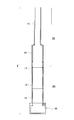
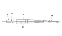
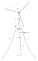
- FIG. 1 is a schematic view of an offshore wind power generation facility 1 according to the present invention.
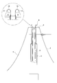
- 2 is a longitudinal sectional view of a floating body 2.
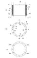
- FIG. The precast cylindrical body 12 (13) is shown, (A) is a longitudinal sectional view, (B) is a plan view (a view taken along the line B-B), and (C) is a bottom view (a view taken along the line C-C).
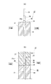
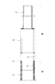
- FIG. 4 is a schematic diagram (A) and (B) of the tight connection between precast cylindrical bodies 12 (13). It is a longitudinal cross-sectional view which shows an upper steel floating body structure part. It is construction procedure figure (the 1) of offshore wind power generation equipment. It is construction procedure figure (the 2) of offshore wind power generation equipment. It is construction procedure figure (the 3) of offshore wind power generation equipment.
- the offshore wind turbine power generation facility 1 includes a floating body 2, a deck 3 installed on the top of the floating body 2, mooring lines 4, 4... Connected to the deck 3, and the deck 3.
- the tower 5 is provided on the top of the tower 5, and the nacelle 6 and the plurality of windmill blades 7, 7.
- the floating body 2 is formed by stacking a plurality of precast cylindrical bodies 12 to 13 made of concrete in the height direction, and the precast cylindrical bodies 12 to 13 are tightly joined by a PC steel material.
- the lower concrete floating structure 2A and the upper steel floating structure 2B connected to the upper side of the lower concrete floating structure 2A, and the bottomed hollow part having an open upper end
- the tower 5 can be moved up and down by a tower lifting device provided on the deck 3 at the time of construction and can be accommodated inside the floating body 2.
- the flood water L of the floating body 2 is set to approximately 60 m or more in the case of 2 MW class power generation equipment.
- the floating body 2 includes a bottomed cylindrical ballast portion 10, a lower concrete floating structure portion 2 ⁇ / b> A connected to the upper surface of the ballast portion 10, and the lower concrete floating structure portion. It consists of the upper steel floating body structure part 2B provided continuously on the upper side of 2A.
- the ballast portion 10 and the lower concrete floating structure portion 2A are all concrete precast members.
- a synthetic precast member 13 is interposed at the boundary between the lower concrete floating structure 2A and the upper steel floating structure 2B, and both are joined.
- the upper steel floating body structure portion 2B has a variable cross-sectional shape in which the outer diameter dimension is gradually reduced in the height direction. In the illustrated example, it has a two-stage variable cross-sectional shape.
- the lower concrete floating body structure portion 2A is composed of a precast cylindrical body 12 made of concrete and a lower half portion of the synthetic precast member 13.
- the precast cylindrical body 12 is a circular cylindrical precast member having the same cross section in the axial direction, and each is manufactured using the same mold or by centrifugal molding. The manufactured hollow precast member is used.
- sheaths 21, 21... For inserting the PC steel bars 19 are embedded in the wall surface at appropriate intervals in the circumferential direction.
- a sheath widened portion 21a is formed at the lower end of the sheaths 21, 21... So that a coupler for connecting the PC steel bars 19 can be inserted, and a fixing anchor plate is fitted on the upper portion.
- a box opening portion 22 is provided for installation.
- a plurality of suspension fittings 23 are provided on the upper surface.
- the precast cylindrical bodies 12 are fastened by inserting the PC steel rods 19, 19... Extended upward from the lower-stage precast cylindrical body 12 into the sheaths 21, 21.
- the anchor plate 24 is fitted into the box opening portion 22, and tension is introduced into the PC steel bar 19 by the nut member 25 to achieve integration.
- a grout material is injected into the sheath 21 from the grout injection hole 27.
- the hole 24a formed in the anchor plate 24 is a grout injection confirmation hole, and the filling of the grout material is completed when the grout material is discharged from the confirmation hole.
- the synthetic precast member 13 has a composite structure of a concrete precast tubular body 16 and a steel tubular body 17. These are manufactured integrally.
- the precast tubular body 16 has an outer diameter dimension obtained by reducing the thickness of the steel tubular body 17, and the lower half portion of the steel tubular body 17 is fitted on the outer periphery.
- the upper end surface of the precast cylindrical body 16 is a fastening surface of the PC steel rod 19.
- the upper steel floating structure 2B is composed of an upper half portion of the synthetic precast member 13 and steel tubular bodies 14 and 15.
- the lower-stage steel tubular body 14 has the same outer diameter as that of the synthetic precast member 13 and is connected to the synthetic precast member 13 by bolts, welding, or the like (in the illustrated example, bolt fastening).
- the upper-stage steel tubular body 15 has an outer diameter smaller than that of the lower-stage steel tubular body 14 and has a variable cross-sectional shape. They are connected by welding or the like (in the illustrated example, bolt fastening).
- the upper end of the upper steel tubular body 15 is left open, the boundary between the upper steel tubular body 15 and the lower steel tubular body 14 and the lower steel tubular body. A space is not partitioned at the boundary between 14 and the steel tubular body 17, and a hollow portion for accommodating the tower 5 is formed inside the floating body 2.
- the tower 5 is made of steel, concrete, or PRC (prestressed reinforced concrete), but is preferably made of steel so as to reduce the total weight.
- the nacelle 6 is a device equipped with a generator that converts the rotation of the windmill into electricity, a controller that can automatically change the angle of the blade, and the like.
- the deck 3 is installed on the floating body 2, one end of the mooring line 4 is tied to the deck 3, and the other end is set on the seabed.
- the floating body 2 is stabilized by being tied to the anchor.
- the tower lifting / lowering equipment 8 is installed on the deck 3 and the tower 5 is pulled up.
- the tower lifting / lowering equipment 8 has center hole jacks 9, 9,... Arranged at predetermined intervals around the base of the tower 5 as shown in the figure, and one end of the PC steel wire 10 is wound around a sheave 11. Then, the center hole jack 9 is tightly connected to the lower end of the tower 5, and the tower 5 can be lowered and raised by the expansion / contraction operation of the center hole jack 9.
- the nacelle 6 is installed and the two wind turbine blades 7 and 7 are installed in a state where the tower 5 is pulled up to an arbitrary height position by the tower elevating equipment 8. Thereafter, as shown in FIG. 11, the tower 5 is slightly lifted and the remaining wind turbine blades 7 are attached.
Abstract
Disclosed is an offshore wind power generator having such advantages that the offshore wind power generator can be easily and safely assembled at sea, maintenance can be facilitated, and the like. The offshore wind power generator comprises a floating body (2), a deck (3) which is installed on the floating body (2), mooring cables (4, 4,...) connected to the deck (3), a tower (5) installed upright on the deck (3), and a nacelle (6) and a plurality of wind turbine blades (7, 7,...) provided at the top of the tower (5), wherein the floating body (2) has a spar-type floating structure consisting of a lower side concrete floating structure (2A) in which respective precast cylindrical bodies (12) made of concrete are stacked in multiple stages in the height direction and fastened tightly by means of a PC steel material (19) and integrated, and an upper side steel floating structure (2B) provided continuously to the upper side of the lower side concrete floating structure (2A) with a bottomed hollow portion opened at the upper end thereof, and the tower (5) can be freely elevated or lowered by a tower hoist (8) provided on the deck (3) at least during construction, and can be housed in the floating body (2).
Description
本発明は、比較的水深の深い海上に設置されるスパー型の洋上風力発電設備及びその施工方法に関する。
The present invention relates to a spar-type offshore wind power generation facility installed on a relatively deep sea and a construction method thereof.
従来より、主として水力、火力及び原子力発電等の発電方式が採用されてきたが、近年は環境や自然エネルギーの有効活用の点から自然風を利用して発電を行う風力発電が注目されている。この風力発電設備には、陸上設置式と、水上(主として海上)設置式とがあるが、沿岸域から後背に山岳地形をかかえる我が国の場合は、沿岸域に安定した風が見込める平野が少ない状況にある。一方、日本は四方を海で囲まれており、海上は発電に適した風が容易に得られるとともに、設置の制約が少ないなどの利点を有する。そこで、近年は洋上風力発電設備又は浮体構造が多く提案されている。
Conventionally, power generation methods such as hydropower, thermal power, and nuclear power generation have been mainly employed, but in recent years, wind power generation that generates power using natural wind has attracted attention in terms of effective use of the environment and natural energy. There are two types of wind power generation facilities: land-based and water-based (mainly sea-based). In Japan, where mountainous landforms are located behind the coast, there are few plains where stable wind can be expected in the coast. It is in. On the other hand, Japan is surrounded on all sides by the sea, and it has the advantage that the wind suitable for power generation can be easily obtained and there are few restrictions on installation. In recent years, therefore, many offshore wind power generation facilities or floating structures have been proposed.
例えば、下記特許文献1では、中空四角柱状の構造物を組み合わせて平面三角形状の水に浮く浮体を構成し、この上に発電用風車を設けた風力発電装置が提案されている。この浮体は水面に浮かぶため「ポンツーン型」と呼ばれている。
For example, in Patent Document 1 below, a wind power generator is proposed in which a floating body that floats on a plane triangular water is formed by combining hollow square columnar structures, and a wind turbine for power generation is provided thereon. This floating body floats on the surface of the water and is called “pontoon type”.
また、下記特許文献2では、上部に物品が載置される複数の浮体部と、所定中心に内端を連結して水平放射方向に延在した外端に前記各浮体部を連結する長手状の剛体からなる連結部と、前記浮体部の間に引張力を生じる引張部とを備えた浮体構造が提案されている。
Further, in Patent Document 2 below, a plurality of floating body portions on which articles are placed, and a longitudinal shape that connects each floating body portion to an outer end extending in a horizontal radial direction by connecting an inner end to a predetermined center. There has been proposed a floating body structure including a connecting portion made of a rigid body and a tension portion that generates a tensile force between the floating body portions.
下記特許文献3では、水に浮遊する複数の浮体部と、前記浮体部を環状に連結する剛体からなる連結部と、環状のほぼ中央部を水底に係留する係留手段と、前記浮体部の位置を検出する位置検出手段と、潮流を検出する潮流検出手段と、潮流に対して角度を可変する態様で複数の浮体部に取り付けた舵と、各舵の角度を潮流に対して調整することによって環状のほぼ中央部を中心とした各浮体部の位置を可変する位置制御部とを備えた浮体構造が提案されている。前記特許文献2,3に係る浮体構造は、浮体を水面下に沈めた状態で浮くため「セミサブ型」と呼ばれている。
In the following Patent Document 3, a plurality of floating body portions floating in water, a connecting portion made of a rigid body that connects the floating body portions in an annular shape, mooring means for anchoring an annular substantially central portion on the water bottom, and the position of the floating body portion A position detecting means for detecting a tidal current, a tidal current detecting means for detecting a tidal current, a rudder attached to a plurality of floating bodies in a manner in which the angle is variable with respect to the tidal current, and adjusting the angle of each rudder with respect to the tidal current There has been proposed a floating body structure including a position control unit that varies the position of each floating body centering around an annular substantially central portion. The floating structure according to Patent Documents 2 and 3 is called a “semi-sub type” because it floats in a state where the floating body is submerged below the water surface.
更に、下記特許文献4では、上下の蓋体と、これらの間に連続的に設置された筒状のプレキャストコンクリートブロックとがPC鋼材で一体接合されてなる下部浮体と、該下部浮体にPC鋼材で一体接合された、上記プレキャストコンクリートブロックよりも小径なプレキャストコンクリートブロックと上蓋とからなる上部浮体とから構成され、下部浮体の下部内側に隔壁によって複数のバラストタンクが形成され、上部浮体の内側には隔壁によって複数の水密区画部が形成された洋上風力発電の浮体構造が提案されている。この特許文献4は、釣浮きのように起立状態で浮くため「スパー型」と呼ばれている。
Furthermore, in the following Patent Document 4, a lower floating body in which upper and lower lids and a cylindrical precast concrete block continuously installed between them are integrally joined with a PC steel material, and the lower floating body with a PC steel material. The upper float is composed of a precast concrete block having a smaller diameter than the precast concrete block and the upper lid, and a plurality of ballast tanks are formed inside the lower float by a partition wall inside the upper float. Has proposed a floating structure for offshore wind power generation in which a plurality of watertight compartments are formed by partition walls. This patent document 4 is called a “spar type” because it floats in a standing state like a fishing float.
前記スパー型浮体は、1つの浮体に1基の風車しか取付けできないが、他のポンツーン型やセミサブ型に比べて、経済性に優れており、浮体の安定性に優れているという利点を有する。
The spar type floating body can attach only one wind turbine to one floating body, but has the advantages that it is more economical than the other pontoon type and semi-sub type, and has excellent floating body stability.
前記スパー型浮体による風力発電設備の施工は、陸上の製作ヤードで組み立てた後、海上を曳航して洋上設置場所まで運び、バラスト水を投入することによって起立状態で浮かばせた後、大型起重機船を用いて、タワー、ナセル及び風車ブレードを取り付ける手順による。しかし、タワーの高さが50~80mにも及ぶため、ナセルや風車ブレードの取付けが高所作業となり危険性が高いとともに、これらのメンテナンスも高所作業となるなどの問題があった。更には、強風又は波浪時における揺動が大きく損傷のおそれがあるなどの問題もあった。
The construction of the wind power generation facility using the spar type floating body is assembled in an onshore production yard, then towed to the ocean, carried to the offshore installation site, and floated in a standing state by throwing in ballast water. Use the procedure to install the tower, nacelle and windmill blade. However, since the height of the tower is as high as 50 to 80 m, the installation of nacelle and windmill blades is a high place work and there is a high risk, and these maintenance work is also a high place work. Furthermore, there has been a problem that there is a risk of damage due to large swinging in strong winds or waves.
そこで本発明の主たる課題は、洋上で容易かつ安全に設置が行えるようにするとともに、メンテナンスが容易に行える、強風又は波浪時における安定性を確保し得るなどの利点を備えた洋上風力発電設備とその施工方法を提供することにある。
Therefore, the main problem of the present invention is that the offshore wind power generation equipment has advantages such as easy and safe installation on the sea, easy maintenance, and ensuring stability in strong winds or waves. It is to provide the construction method.
前記課題を解決するために請求項1に係る本発明として、浮体と、この浮体の上部に設置されるデッキと、このデッキに繋がれた係留索と、前記デッキの上に立設されるタワーと、このタワーの頂部に設備されるナセル及び複数の風車ブレードからなる洋上風力発電設備であって、
前記浮体は、コンクリート製のプレキャスト筒状体を高さ方向に複数段積み上げ、各プレキャスト筒状体をPC鋼材により緊結し一体化を図った下側コンクリート製浮体構造部と、この下側コンクリート浮体構造部の上側に連設された上側鋼製浮体構造部とからなるとともに、上端部を開口させた有底中空部を有するスパー型の浮体構造とし、少なくとも施工時に前記タワーは前記デッキ上に設けたタワー昇降設備によって昇降自在とされ、前記浮体内部に収容可能とされることを特徴とする洋上風力発電設備が提供される。 In order to solve the above-mentioned problems, the present invention according toclaim 1 includes a floating body, a deck installed above the floating body, a mooring line connected to the deck, and a tower standing on the deck. And an offshore wind power generation facility consisting of a nacelle and a plurality of windmill blades installed at the top of this tower,
The floating body includes a lower concrete floating body structure in which a plurality of precast cylindrical bodies made of concrete are stacked in the height direction, and each precast cylindrical body is fastened and integrated with PC steel, and the lower concrete floating body And a spar type floating structure having a bottomed hollow part with an open upper end, and at least during construction, the tower is provided on the deck. There is provided an offshore wind power generation facility that can be moved up and down by a tower lifting and lowering facility and can be accommodated inside the floating body.
前記浮体は、コンクリート製のプレキャスト筒状体を高さ方向に複数段積み上げ、各プレキャスト筒状体をPC鋼材により緊結し一体化を図った下側コンクリート製浮体構造部と、この下側コンクリート浮体構造部の上側に連設された上側鋼製浮体構造部とからなるとともに、上端部を開口させた有底中空部を有するスパー型の浮体構造とし、少なくとも施工時に前記タワーは前記デッキ上に設けたタワー昇降設備によって昇降自在とされ、前記浮体内部に収容可能とされることを特徴とする洋上風力発電設備が提供される。 In order to solve the above-mentioned problems, the present invention according to
The floating body includes a lower concrete floating body structure in which a plurality of precast cylindrical bodies made of concrete are stacked in the height direction, and each precast cylindrical body is fastened and integrated with PC steel, and the lower concrete floating body And a spar type floating structure having a bottomed hollow part with an open upper end, and at least during construction, the tower is provided on the deck. There is provided an offshore wind power generation facility that can be moved up and down by a tower lifting and lowering facility and can be accommodated inside the floating body.
上記請求項1記載の発明では、浮体をコンクリート製のプレキャスト筒状体を高さ方向に複数段積み上げ、各プレキャスト筒状体をPC鋼材により緊結し一体化を図った下側コンクリート製浮体構造部と、この下側コンクリート浮体構造部の上側に連設された上側鋼製浮体構造部とからなるとともに、上端部を開口させた有底中空部を有するスパー型の浮体構造とするものである。
In the first aspect of the present invention, the lower concrete floating structure in which the floating body is made of a plurality of precast cylindrical bodies made of concrete and stacked in the height direction, and each precast cylindrical body is fastened and integrated with PC steel. And a spar type floating body structure having a bottomed hollow portion having an upper end opened, and an upper steel floating body structure portion continuously provided on the upper side of the lower concrete floating body structure portion.
従って、後述の請求項3に示す施工手順に示すように、タワーを浮体内に収容した状態で曳航し、バラストを投入することによって浮体を直立状態に起立させ、タワー昇降設備によってタワーを任意の高さ位置まで引き上げた状態で、前記ナセルを設置するとともに、風車ブレードを設置し、すべての部材取付けが完了した後、タワーを正規の高さ位置まで引き上げ固定する手順とすることにより、タワーを下降させた状態でナセルや風車ブレードの取付けができるようになり高所作業が減って安全に施工できるようになる。また、供用後のメンテナンス時にタワーを下降させることにより安全に作業が行えるようになるとともに、強風や波浪時にも、タワーを下降させることにより安定性が増し損傷のおそれも少なくなる。
Therefore, as shown in the construction procedure described in claim 3 to be described later, the tower is towed in a state of being accommodated in the floating body, and the floating body is erected in an upright state by throwing in the ballast. With the nacelle installed in the state of being pulled up to the height position, the wind turbine blades are installed, and after the installation of all members is completed, the tower is lifted and fixed to the normal height position. The nacelle and windmill blade can be attached in the lowered state, and the work at a high place is reduced, enabling safe construction. In addition, the work can be safely performed by lowering the tower during maintenance after service, and the stability is increased and the risk of damage is reduced by lowering the tower even during strong winds or waves.
さらに、下側コンクリート製浮体構造部と上側鋼製浮体構造部とからなる浮体構造とすることにより、重心を低くすることができるため、浮体の安定性が増すとともに、浮体の長さ寸法を低減することが可能となる。海上に突出している部分が鋼製のため、船舶の衝突に対して有利になるなどの効果がもたらされるようになる。
Furthermore, since the center of gravity can be lowered by adopting a floating structure consisting of the lower concrete floating structure and the upper steel floating structure, the stability of the floating structure is increased and the length of the floating structure is reduced. It becomes possible to do. Since the portion that protrudes on the sea is made of steel, it is advantageous in that it is advantageous for a ship collision.
請求項2に係る本発明として、前記上側鋼製浮体構造部は、高さ方向に段階的に外径寸法が縮小される変断面形状としてある請求項1記載の洋上風力発電設備が提供される。
As the present invention according to claim 2, the offshore wind power generation facility according to claim 1 is provided, wherein the upper steel floating structure has a variable cross-sectional shape in which the outer diameter dimension is gradually reduced in the height direction. .
上記請求項2記載の発明は、上側鋼製浮体構造部を、高さ方向に段階的に外径寸法が縮小される変断面形状とするものである。従って、重心が低くなり強風や波浪に対する安定性が増すようになるとともに、上部側を相対的に小径断面としたことにより平常時に波の影響を受けづらくなる。
The invention described in claim 2 is such that the upper steel floating structure has a variable cross-sectional shape whose outer diameter is gradually reduced in the height direction. Accordingly, the center of gravity is lowered and stability against strong winds and waves is increased, and the upper side is relatively small in diameter so that it is less likely to be affected by waves in normal times.
請求項3に係る本発明として、請求項1、2いずれかに記載の洋上風力発電設備を洋上に設置するための施工方法であって、
浮体内部にタワーを収容させた状態で海上に横向きで浮かべ、洋上設置場所まで曳航する第1手順と、
洋上設置場所において、バラストを投入することによって浮体を直立状態に起立させる第2手順と、
前記タワー昇降設備によってタワーを任意の高さ位置まで引き上げた状態で、前記ナセルを設置するとともに、風車ブレードを設置する第3手順と、
タワーを正規の高さ位置まで引き上げ固定する第4手順とからなる洋上風力発電設備の施工方法が提供される。 The present invention according toclaim 3 is a construction method for installing the offshore wind power generation facility according to any of claims 1 and 2 on the ocean,
A first step of floating sideways on the sea with the tower housed inside the floating body and towing to the offshore installation location;
A second procedure for raising the floating body in an upright state by inserting ballast at an offshore installation location;
A third step of installing the nacelle and the wind turbine blade in a state where the tower is raised to an arbitrary height position by the tower lifting equipment;
A construction method of an offshore wind power generation facility is provided, which includes a fourth step of lifting and fixing the tower to a normal height position.
浮体内部にタワーを収容させた状態で海上に横向きで浮かべ、洋上設置場所まで曳航する第1手順と、
洋上設置場所において、バラストを投入することによって浮体を直立状態に起立させる第2手順と、
前記タワー昇降設備によってタワーを任意の高さ位置まで引き上げた状態で、前記ナセルを設置するとともに、風車ブレードを設置する第3手順と、
タワーを正規の高さ位置まで引き上げ固定する第4手順とからなる洋上風力発電設備の施工方法が提供される。 The present invention according to
A first step of floating sideways on the sea with the tower housed inside the floating body and towing to the offshore installation location;
A second procedure for raising the floating body in an upright state by inserting ballast at an offshore installation location;
A third step of installing the nacelle and the wind turbine blade in a state where the tower is raised to an arbitrary height position by the tower lifting equipment;
A construction method of an offshore wind power generation facility is provided, which includes a fourth step of lifting and fixing the tower to a normal height position.
上記請求項3記載の発明によれば、タワーを下降させた状態でナセルや風車ブレードの取付けができるようになり高所作業が減って安全に施工できるようになる。
According to the third aspect of the present invention, the nacelle and the wind turbine blade can be attached in a state where the tower is lowered, so that the work at a high place is reduced and the construction can be performed safely.
以上詳説のとおり本発明によれば、洋上で容易かつ安全に設置が行えるようになるとともに、メンテナンスが容易に行える、強風又は波浪時における安定性を確保し得るなどの利点を備えた洋上風力発電設備とすることができる。
As described above in detail, according to the present invention, offshore wind power generation has advantages such as easy and safe installation on the ocean, easy maintenance, and stability during strong winds or waves. It can be equipment.
以下、本発明の実施の形態について図面を参照しながら詳述する。
Hereinafter, embodiments of the present invention will be described in detail with reference to the drawings.
図1に示されるように、洋上風車発電設備1は、浮体2と、この浮体2の上部に設置されるデッキ3と、このデッキ3に繋がれた係留索4、4…と、前記デッキ3の上に立設されるタワー5と、このタワー5の頂部に設備されるナセル6及び複数の風車ブレード7,7…からなるものである。
As shown in FIG. 1, the offshore wind turbine power generation facility 1 includes a floating body 2, a deck 3 installed on the top of the floating body 2, mooring lines 4, 4... Connected to the deck 3, and the deck 3. The tower 5 is provided on the top of the tower 5, and the nacelle 6 and the plurality of windmill blades 7, 7.
そして、前記浮体2は、図2に示されるように、コンクリート製のプレキャスト筒状体12~13を高さ方向に複数段積み上げ、各プレキャスト筒状体12~13をPC鋼材により緊結し一体化を図った下側コンクリート製浮体構造部2Aと、この下側コンクリート浮体構造部2Aの上側に連設された上側鋼製浮体構造部2Bとからなるとともに、上端部を開口させた有底中空部を有するスパー型の浮体構造とし、前記タワー5は少なくとも施工時に前記デッキ3上に設けたタワー昇降設備によって昇降自在とされ、前記浮体2内部に収容可能となっているものである。前記浮体2の吃水Lは、2MW級発電設備の場合概ね60m以上に設定される。
As shown in FIG. 2, the floating body 2 is formed by stacking a plurality of precast cylindrical bodies 12 to 13 made of concrete in the height direction, and the precast cylindrical bodies 12 to 13 are tightly joined by a PC steel material. The lower concrete floating structure 2A and the upper steel floating structure 2B connected to the upper side of the lower concrete floating structure 2A, and the bottomed hollow part having an open upper end The tower 5 can be moved up and down by a tower lifting device provided on the deck 3 at the time of construction and can be accommodated inside the floating body 2. The flood water L of the floating body 2 is set to approximately 60 m or more in the case of 2 MW class power generation equipment.
以下、更に具体的に詳述する。
The details will be described in more detail below.
前記浮体2は、図2に示されるように、有底円筒形状のバラスト部10と、このバラスト部10の上面に連設された下側コンクリート浮体構造部2Aと、この下側コンクリート浮体構造部2Aの上側に連設された上側鋼製浮体構造部2Bとからなる。前記バラスト部10及び下側コンクリート浮体構造部2Aはすべてコンクリートのプレキャスト部材とされる。下側コンクリート浮体構造部2Aと上側鋼製浮体構造部2Bとの境界部に合成プレキャスト部材13が介在され、両者が接合されている。前記上側鋼製浮体構造部2Bは、高さ方向に段階的に外径寸法が縮小される変断面形状としてある。図示例では2段階の変断面形状としてある。
As shown in FIG. 2, the floating body 2 includes a bottomed cylindrical ballast portion 10, a lower concrete floating structure portion 2 </ b> A connected to the upper surface of the ballast portion 10, and the lower concrete floating structure portion. It consists of the upper steel floating body structure part 2B provided continuously on the upper side of 2A. The ballast portion 10 and the lower concrete floating structure portion 2A are all concrete precast members. A synthetic precast member 13 is interposed at the boundary between the lower concrete floating structure 2A and the upper steel floating structure 2B, and both are joined. The upper steel floating body structure portion 2B has a variable cross-sectional shape in which the outer diameter dimension is gradually reduced in the height direction. In the illustrated example, it has a two-stage variable cross-sectional shape.
以下、更に具体的に詳述する。
The details will be described in more detail below.
前記下側コンクリート浮体構造部2Aは、コンクリート製のプレキャスト筒状体12…と、合成プレキャスト部材13の下半部分とで構成されている。前記プレキャスト筒状体12は、図3に示されるように、軸方向に同一断面とされる円形筒状のプレキャスト部材であり、それぞれが同一の型枠を用いて製作されるか、遠心成形により製造された中空プレキャスト部材が用いられる。
The lower concrete floating body structure portion 2A is composed of a precast cylindrical body 12 made of concrete and a lower half portion of the synthetic precast member 13. As shown in FIG. 3, the precast cylindrical body 12 is a circular cylindrical precast member having the same cross section in the axial direction, and each is manufactured using the same mold or by centrifugal molding. The manufactured hollow precast member is used.
壁面内には鉄筋20の他、周方向に適宜の間隔でPC鋼棒19を挿通するためのシース21、21…が埋設されている。このシース21、21…の下端部にはPC鋼棒19同士を連結するためのカップラーを挿入可能とするためにシース拡径部21aが形成されているとともに、上部には定着用アンカープレートを嵌設するための箱抜き部22が形成されている。また、上面には吊り金具23が複数設けられている。
In addition to the reinforcing bars 20, sheaths 21, 21... For inserting the PC steel bars 19 are embedded in the wall surface at appropriate intervals in the circumferential direction. A sheath widened portion 21a is formed at the lower end of the sheaths 21, 21... So that a coupler for connecting the PC steel bars 19 can be inserted, and a fixing anchor plate is fitted on the upper portion. A box opening portion 22 is provided for installation. In addition, a plurality of suspension fittings 23 are provided on the upper surface.
プレキャスト筒状体12同士の緊結は、図4(A)に示されるように、下段側プレキャスト筒状体12から上方に延長されたPC鋼棒19、19…をシース21、21…に挿通させながらプレキャスト筒状体12,12を積み重ねたならば、アンカープレート24を箱抜き部22に嵌設し、ナット部材25によりPC鋼棒19に張力を導入し一体化を図る。また、グラウト注入孔27からグラウト材をシース21内に注入する。なお、前記アンカープレート24に形成された孔24aはグラウト注入確認孔であり、該確認孔からグラウト材が吐出されたことをもってグラウト材の充填を終了する。
As shown in FIG. 4 (A), the precast cylindrical bodies 12 are fastened by inserting the PC steel rods 19, 19... Extended upward from the lower-stage precast cylindrical body 12 into the sheaths 21, 21. However, if the precast cylindrical bodies 12 and 12 are stacked, the anchor plate 24 is fitted into the box opening portion 22, and tension is introduced into the PC steel bar 19 by the nut member 25 to achieve integration. Further, a grout material is injected into the sheath 21 from the grout injection hole 27. The hole 24a formed in the anchor plate 24 is a grout injection confirmation hole, and the filling of the grout material is completed when the grout material is discharged from the confirmation hole.
次に、図4(B)に示されるように、PC鋼棒19の突出部に対してカップラー26を螺合し、上段側のPC鋼棒19、19…を連結したならば、上段となるプレキャスト筒状体12のシース21、21…に前記PC鋼棒19、19…を挿通させながら積み重ね、前記要領によりPC鋼棒19の定着を図る手順を順次繰り返すことにより高さ方向に積み上げられる。この際、下段側プレキャスト筒状体12と上段側プレキャスト筒状体12との接合面には止水性確保及び合わせ面の接合のためにエポキシ樹脂系などの接着剤28やシール材が塗布される。
Next, as shown in FIG. 4 (B), when the coupler 26 is screwed into the protruding portion of the PC steel bar 19 and the upper PC steel bars 19, 19,. The PC steel rods 19, 19 are stacked while being inserted through the sheaths 21, 21 ... of the precast cylindrical body 12, and the procedure for fixing the PC steel rod 19 is sequentially repeated according to the above procedure. At this time, an adhesive 28 such as an epoxy resin or a sealing material is applied to the joint surface between the lower-stage precast tubular body 12 and the upper-stage precast tubular body 12 in order to ensure waterproofness and join the mating surfaces. .
次いで、前記合成プレキャスト部材13は、図5にも示されるように、コンクリート製のプレキャスト筒状体16と鋼製筒状体17との合成構造である。これらは一体的に製作される。前記プレキャスト筒状体16は、前記鋼製筒状体17の肉厚分の厚さを減じた外径寸法とされ、この外周に前記鋼製筒状体17の下半部分が外嵌された構造とし、前記プレキャスト筒状体16の上端面がPC鋼棒19の締結面とされる。
Next, as shown in FIG. 5, the synthetic precast member 13 has a composite structure of a concrete precast tubular body 16 and a steel tubular body 17. These are manufactured integrally. The precast tubular body 16 has an outer diameter dimension obtained by reducing the thickness of the steel tubular body 17, and the lower half portion of the steel tubular body 17 is fitted on the outer periphery. The upper end surface of the precast cylindrical body 16 is a fastening surface of the PC steel rod 19.
前記上側鋼製浮体構造部2Bは、前記合成プレキャスト部材13の上半部分と、鋼製筒状体14,15とで構成されている。下段側の鋼製筒状体14は、合成プレキャスト部材13と同一の外径寸法とされ、合成プレキャスト部材13に対して、ボルト又は溶接等(図示例はボルト締結)によって連結される。上段側の鋼製筒状体15は、前記下段側の鋼製筒状体14よりも外径寸法が縮小され、変断面形状とされ、下段側の鋼製筒状体14に対してボルト又は溶接等(図示例はボルト締結)によって連結される。前記上段側鋼製筒状体15の上端は開口のままとされるとともに、前記上段側鋼製筒状体15及び下段側鋼製筒状体14との境界部及び下段側鋼製筒状体14と鋼製筒状体17との境界部は空間が仕切られておらず、浮体2内部にはタワー5を収容するための中空部が形成されている。
The upper steel floating structure 2B is composed of an upper half portion of the synthetic precast member 13 and steel tubular bodies 14 and 15. The lower-stage steel tubular body 14 has the same outer diameter as that of the synthetic precast member 13 and is connected to the synthetic precast member 13 by bolts, welding, or the like (in the illustrated example, bolt fastening). The upper-stage steel tubular body 15 has an outer diameter smaller than that of the lower-stage steel tubular body 14 and has a variable cross-sectional shape. They are connected by welding or the like (in the illustrated example, bolt fastening). The upper end of the upper steel tubular body 15 is left open, the boundary between the upper steel tubular body 15 and the lower steel tubular body 14 and the lower steel tubular body. A space is not partitioned at the boundary between 14 and the steel tubular body 17, and a hollow portion for accommodating the tower 5 is formed inside the floating body 2.
一方、前記タワー5は、鋼材、コンクリート又はPRC(プレストレスト鉄筋コンクリート)から構成されるものが使用されるが、好ましいのは総重量が小さくなるように鋼材によって製作されたものを用いるのが望ましい。また、前記ナセル6は、風車の回転を電気に変換する発電機やブレードの角度を自動的に変えることができる制御器などが搭載された装置である。
On the other hand, the tower 5 is made of steel, concrete, or PRC (prestressed reinforced concrete), but is preferably made of steel so as to reduce the total weight. The nacelle 6 is a device equipped with a generator that converts the rotation of the windmill into electricity, a controller that can automatically change the angle of the blade, and the like.
〔施工手順〕
以下、図6~図12に基づき、前記洋上風力発電設備1の施工手順について詳述する。
(第1手順)
製作ヤードに隣接した洋上において、図6に示されるように、浮体2内部にタワー5を収容した状態で海上に横向きで浮かべ、バラスト水31を注水し吃水を調整した後、曳航船18により洋上設置場所まで曳航する。なお、下側コンクリート浮体構造部2Aと、上側鋼製浮体構造部2Bとでは、下側コンクリート浮体構造部2A側の方が重いため、バランス調整用浮体32を浮かべるとともに、この浮体上に設置したウインチ33から繰り出されたワイヤの一端を下側コンクリート浮体構造部2Aの端部に連結し、浮体2が水平になるように調整する。なお、浮体2内部にタワー5を収容した状態で、前記上段側鋼製筒状体15の上端開口は塞がれている。 [Construction procedure]
The construction procedure of the offshore windpower generation facility 1 will be described in detail below with reference to FIGS.
(First procedure)
On the ocean adjacent to the production yard, as shown in FIG. 6, thetower 5 is accommodated inside the floating body 2 and floated sideways on the ocean. Tow to installation location. In the lower concrete floating structure 2A and the upper steel floating structure 2B, since the lower concrete floating structure 2A is heavier, the balance adjusting floating body 32 is floated and installed on the floating structure. One end of the wire fed out from the winch 33 is connected to the end of the lower concrete floating body structure portion 2A, and the floating body 2 is adjusted to be horizontal. In the state where the tower 5 is accommodated inside the floating body 2, the upper end opening of the upper steel tubular body 15 is closed.
以下、図6~図12に基づき、前記洋上風力発電設備1の施工手順について詳述する。
(第1手順)
製作ヤードに隣接した洋上において、図6に示されるように、浮体2内部にタワー5を収容した状態で海上に横向きで浮かべ、バラスト水31を注水し吃水を調整した後、曳航船18により洋上設置場所まで曳航する。なお、下側コンクリート浮体構造部2Aと、上側鋼製浮体構造部2Bとでは、下側コンクリート浮体構造部2A側の方が重いため、バランス調整用浮体32を浮かべるとともに、この浮体上に設置したウインチ33から繰り出されたワイヤの一端を下側コンクリート浮体構造部2Aの端部に連結し、浮体2が水平になるように調整する。なお、浮体2内部にタワー5を収容した状態で、前記上段側鋼製筒状体15の上端開口は塞がれている。 [Construction procedure]
The construction procedure of the offshore wind
(First procedure)
On the ocean adjacent to the production yard, as shown in FIG. 6, the
(第2手順)
図7に示されるように、洋上設置場所に到着したならば、バラスト水31を注水するとともに、前記バランス調整用浮体32上のウインチ33からワイヤを徐々に繰り出すことにより、ゆっくりと浮体2を直立状態に起立させる。 (Second procedure)
As shown in FIG. 7, when arriving at the offshore installation location, theballast water 31 is poured, and the wire 2 is gradually fed out from the winch 33 on the balance adjusting floating body 32, so that the floating body 2 is slowly upright. Stand up to the state.
図7に示されるように、洋上設置場所に到着したならば、バラスト水31を注水するとともに、前記バランス調整用浮体32上のウインチ33からワイヤを徐々に繰り出すことにより、ゆっくりと浮体2を直立状態に起立させる。 (Second procedure)
As shown in FIG. 7, when arriving at the offshore installation location, the
図8に示されるように、浮体2を起立させたならば、浮体2の上部にデッキ3を設置するとともに、前記デッキ3に係留索4の一端を繋ぎ止めるとともに、他端を海底に沈設したアンカーに繋ぎ留めて浮体2の安定を図る。
As shown in FIG. 8, when the floating body 2 is erected, the deck 3 is installed on the floating body 2, one end of the mooring line 4 is tied to the deck 3, and the other end is set on the seabed. The floating body 2 is stabilized by being tied to the anchor.
(第3手順)
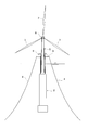
デッキ3上にタワー昇降設備8を設置し、タワー5の引上げ作業に入る。前記タワー昇降設備8は、例えば同図に示されるように、タワー5の基部周囲に所定の間隔でセンターホールジャッキ9,9…を配置するとともに、PC鋼線10の一端をシーブ11を巻回させた後、センターホールジャッキ9を通してタワー5の下端に緊結し、前記センターホールジャッキ9の伸縮操作により、タワー5の下降と上昇とを可能とした設備である。 (Third procedure)
The tower lifting / loweringequipment 8 is installed on the deck 3 and the tower 5 is pulled up. The tower lifting / lowering equipment 8 has center hole jacks 9, 9,... Arranged at predetermined intervals around the base of the tower 5 as shown in the figure, and one end of the PC steel wire 10 is wound around a sheave 11. Then, the center hole jack 9 is tightly connected to the lower end of the tower 5, and the tower 5 can be lowered and raised by the expansion / contraction operation of the center hole jack 9.
デッキ3上にタワー昇降設備8を設置し、タワー5の引上げ作業に入る。前記タワー昇降設備8は、例えば同図に示されるように、タワー5の基部周囲に所定の間隔でセンターホールジャッキ9,9…を配置するとともに、PC鋼線10の一端をシーブ11を巻回させた後、センターホールジャッキ9を通してタワー5の下端に緊結し、前記センターホールジャッキ9の伸縮操作により、タワー5の下降と上昇とを可能とした設備である。 (Third procedure)
The tower lifting / lowering
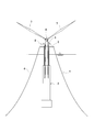
図10に示されるように、前記タワー昇降設備8により、タワー5を任意の高さ位置まで引き上げた状態で、前記ナセル6を設置するとともに、2枚の風車ブレード7,7を設置する。
その後、図11に示されるように、若干タワー5を引き上げて、残りの風車ブレード7を取り付ける。 As shown in FIG. 10, thenacelle 6 is installed and the two wind turbine blades 7 and 7 are installed in a state where the tower 5 is pulled up to an arbitrary height position by the tower elevating equipment 8.
Thereafter, as shown in FIG. 11, thetower 5 is slightly lifted and the remaining wind turbine blades 7 are attached.
その後、図11に示されるように、若干タワー5を引き上げて、残りの風車ブレード7を取り付ける。 As shown in FIG. 10, the
Thereafter, as shown in FIG. 11, the
(第4手順)
すべての部材取付け作業を終えたならば、図12に示されるように、前記タワー昇降設備8によってタワー5を上昇させたならば、タワー固定用ベース金具34等によりタワー5を正規の高さ位置に固定し施工を完了する。 (4th procedure)
When all the members are attached, as shown in FIG. 12, when thetower 5 is raised by the tower lifting / lowering equipment 8, the tower 5 is moved to the normal height position by the tower fixing base bracket 34 or the like. Complete the installation by fixing to.
すべての部材取付け作業を終えたならば、図12に示されるように、前記タワー昇降設備8によってタワー5を上昇させたならば、タワー固定用ベース金具34等によりタワー5を正規の高さ位置に固定し施工を完了する。 (4th procedure)
When all the members are attached, as shown in FIG. 12, when the
〔他の形態例〕
(1)上記形態例では、バラストとして海水又は水を用いたが、コンクリートブロックを内部に投入しても良いし、バラスト部10の上側にコンクリート筒状体12の外周にコンクリート製のリングを外嵌させるようにしてもよい。これらは併用してもよい。
(2)上記形態例では、前記タワー昇降設備8を撤去したが、残置しておき、その後のメンテナンス時や強風、波浪時にタワー5を下降させる際に使用できるようにしてもよい。もちろん、タワー下降作業時にタワー昇降設備8を新たに設置するようにしてもよい。 [Other examples]
(1) In the above embodiment, seawater or water is used as the ballast. However, a concrete block may be put inside, or a concrete ring is attached to the outer periphery of the concretecylindrical body 12 on the upper side of the ballast portion 10. You may make it fit. These may be used in combination.
(2) In the above embodiment, thetower elevating equipment 8 has been removed, but it may be left behind so that it can be used when the tower 5 is lowered during maintenance, strong winds, and waves. Of course, you may make it install the tower raising / lowering installation 8 newly at the time of tower lowering work.
(1)上記形態例では、バラストとして海水又は水を用いたが、コンクリートブロックを内部に投入しても良いし、バラスト部10の上側にコンクリート筒状体12の外周にコンクリート製のリングを外嵌させるようにしてもよい。これらは併用してもよい。
(2)上記形態例では、前記タワー昇降設備8を撤去したが、残置しておき、その後のメンテナンス時や強風、波浪時にタワー5を下降させる際に使用できるようにしてもよい。もちろん、タワー下降作業時にタワー昇降設備8を新たに設置するようにしてもよい。 [Other examples]
(1) In the above embodiment, seawater or water is used as the ballast. However, a concrete block may be put inside, or a concrete ring is attached to the outer periphery of the concrete
(2) In the above embodiment, the
1…洋上風力発電設備、2…浮体、3…デッキ、4…係留索、5…タワー、6…ナセル、7…風車ブレード、8…タワー昇降設備
1 ... Offshore wind power generation equipment, 2 ... Floating body, 3 ... Deck, 4 ... Mooring line, 5 ... Tower, 6 ... Nacelle, 7 ... Windmill blade, 8 ... Tower lifting equipment
Claims (3)
- 浮体と、この浮体の上部に設置されるデッキと、このデッキに繋がれた係留索と、前記デッキの上に立設されるタワーと、このタワーの頂部に設備されるナセル及び複数の風車ブレードからなる洋上風力発電設備であって、
前記浮体は、コンクリート製のプレキャスト筒状体を高さ方向に複数段積み上げ、各プレキャスト筒状体をPC鋼材により緊結し一体化を図った下側コンクリート製浮体構造部と、この下側コンクリート浮体構造部の上側に連設された上側鋼製浮体構造部とからなるとともに、上端部を開口させた有底中空部を有するスパー型の浮体構造とし、少なくとも施工時に前記タワーは前記デッキ上に設けたタワー昇降設備によって昇降自在とされ、前記浮体内部に収容可能とされることを特徴とする洋上風力発電設備。 A floating body, a deck installed on the top of the floating body, a mooring line connected to the deck, a tower standing on the deck, a nacelle and a plurality of windmill blades installed on the top of the tower An offshore wind power generation facility comprising:
The floating body includes a lower concrete floating body structure in which a plurality of precast cylindrical bodies made of concrete are stacked in the height direction, and each precast cylindrical body is fastened and integrated with PC steel, and the lower concrete floating body A spar-type floating structure having a bottomed hollow portion with an upper end opened, and at least during construction, the tower is provided on the deck. An offshore wind power generation facility that can be moved up and down by a tower lifting and lowering facility and can be accommodated inside the floating body. - 前記上側鋼製浮体構造部は、高さ方向に段階的に外径寸法が縮小される変断面形状としてある請求項1記載の洋上風力発電設備。 The offshore wind power generation facility according to claim 1, wherein the upper steel floating body structure has a variable cross-sectional shape in which an outer diameter dimension is gradually reduced in a height direction.
- 請求項1、2いずれかに記載の洋上風力発電設備を洋上に設置するための施工方法であって、
浮体内部にタワーを収容させた状態で海上に横向きで浮かべ、洋上設置場所まで曳航する第1手順と、
洋上設置場所において、バラストを投入することによって浮体を直立状態に起立させる第2手順と、
前記タワー昇降設備によってタワーを任意の高さ位置まで引き上げた状態で、前記ナセルを設置するとともに、風車ブレードを設置する第3手順と、
タワーを正規の高さ位置まで引き上げ固定する第4手順とからなる洋上風力発電設備の施工方法。 A construction method for installing the offshore wind power generation facility according to claim 1 or 2 on the ocean,
A first step of floating sideways on the sea with the tower housed inside the floating body and towing to the offshore installation location;
A second procedure for raising the floating body in an upright state by inserting ballast at an offshore installation location;
A third step of installing the nacelle and the wind turbine blade in a state where the tower is raised to an arbitrary height position by the tower lifting equipment;
A construction method of an offshore wind power generation facility comprising a fourth step of lifting and fixing the tower to a regular height position.
Applications Claiming Priority (2)
| Application Number | Priority Date | Filing Date | Title |
|---|---|---|---|
| JP2009-071884 | 2009-03-24 | ||
| JP2009071884A JP5274329B2 (en) | 2009-03-24 | 2009-03-24 | Offshore wind power generation facility and its construction method |
Publications (1)
| Publication Number | Publication Date |
|---|---|
| WO2010110330A1 true WO2010110330A1 (en) | 2010-09-30 |
Family
ID=42781023
Family Applications (1)
| Application Number | Title | Priority Date | Filing Date |
|---|---|---|---|
| PCT/JP2010/055107 WO2010110330A1 (en) | 2009-03-24 | 2010-03-24 | Offshore wind power generator and construction method thereof |
Country Status (2)
| Country | Link |
|---|---|
| JP (1) | JP5274329B2 (en) |
| WO (1) | WO2010110330A1 (en) |
Cited By (18)
| Publication number | Priority date | Publication date | Assignee | Title |
|---|---|---|---|---|
| EP2479103A1 (en) * | 2011-01-25 | 2012-07-25 | Dcns | Floating support for a structure such as a wind turbine |
| WO2013010738A1 (en) * | 2011-07-18 | 2013-01-24 | Werner Rolf J | Tower-shaped supporting structure |
| WO2013093160A1 (en) | 2011-12-23 | 2013-06-27 | Universitat Politècnica De Catalunya | Floating precast-concrete structure for supporting a wind turbine |
| ES2496390A1 (en) * | 2013-03-18 | 2014-09-18 | Ingecid Investigación Y Desarrollo De Proyectos, S.L. | Foundation structure for wind turbines in the sea (Machine-translation by Google Translate, not legally binding) |
| WO2014163501A1 (en) * | 2013-04-05 | 2014-10-09 | Gustomsc Recourses B.V. | Floating wind turbine |
| US9238896B2 (en) | 2012-12-19 | 2016-01-19 | Universitat Politècnica De Catalunya | Floating structure for supporting a wind turbine |
| US20160025074A1 (en) * | 2013-03-13 | 2016-01-28 | Toda Corporation | Floating offshore wind power generation facility |
| FR3036371A1 (en) * | 2015-05-22 | 2016-11-25 | Jean Pierre Compagnon | FLOATING STRUCTURE ALLOWING THE TOWING OF OFFSHORE WIND TURBINES ON THEIR DEEP SEA OPERATING SITE, EQUIPPED WITH ALL THEIR EQUIPMENT, READY TO OPERATE |
| CN108032062A (en) * | 2018-01-08 | 2018-05-15 | 大连理工大学 | A kind of integral demounting apparatus and method of the marine single pile wind turbine based on explosion |
| CN108860495A (en) * | 2017-05-09 | 2018-11-23 | 上海绿色环保能源有限公司 | Applied to the floatation type blower between shallow water and deep water |
| CN110296051A (en) * | 2019-07-25 | 2019-10-01 | 广州林电科技有限公司 | A kind of small-sized sea-borne wind power generation apparatus with safeguard function |
| CN110371251A (en) * | 2019-07-11 | 2019-10-25 | 上海交通大学 | A kind of novel floatation type list column wind turbine mooring gear |
| CN110371261A (en) * | 2019-07-11 | 2019-10-25 | 上海交通大学 | A kind of basis shallow draft Spar suitable for middle coastal waters domain |
| CN110616667A (en) * | 2019-09-29 | 2019-12-27 | 大连理工大学 | Wave preventing device suitable for installation of offshore floating type fan and method for installing offshore floating type fan |
| WO2020230685A1 (en) * | 2019-05-10 | 2020-11-19 | 国立大学法人大阪大学 | Floating offshore wind turbine and installation method for floating offshore wind turbine |
| WO2021175398A1 (en) * | 2020-03-06 | 2021-09-10 | Vestas Offshore Wind A/S | Method of installing rotor blades on an offshore wind turbine |
| CN114104195A (en) * | 2021-11-25 | 2022-03-01 | 三峡珠江发电有限公司 | Mooring system suitable for medium-shallow water floating type offshore wind power foundation platform |
| CN114348193A (en) * | 2022-01-13 | 2022-04-15 | 东北石油大学 | Self-generating deep sea movable ocean platform system and construction method thereof |
Families Citing this family (11)
| Publication number | Priority date | Publication date | Assignee | Title |
|---|---|---|---|---|
| EP2623290A4 (en) | 2010-09-30 | 2015-01-28 | Asahi Kasei Chemicals Corp | Injection-molded object |
| JP5738642B2 (en) * | 2011-03-25 | 2015-06-24 | 戸田建設株式会社 | Installation method of offshore wind power generation equipment |
| JP5738643B2 (en) * | 2011-03-25 | 2015-06-24 | 戸田建設株式会社 | Installation method of offshore wind power generation equipment |
| CN102734076A (en) * | 2012-07-02 | 2012-10-17 | 袁宗凡 | Water wind power generation system |
| CN104903572B (en) | 2012-11-30 | 2018-08-24 | 菱重维斯塔斯海上风力有限公司 | The component moving method of float type wind power generation plant and the device |
| KR101417835B1 (en) * | 2012-12-12 | 2014-07-09 | 현대건설주식회사 | Structure for offshore wind turbine having extendable tower |
| JP6041906B2 (en) * | 2013-01-21 | 2016-12-14 | 三菱重工業株式会社 | Floating wind power generator assembly method and floating wind power generator |
| PT2933181T (en) | 2013-01-21 | 2018-02-26 | Mhi Vestas Offshore Wind As | Method for maintaining floating wind-power generation device |
| KR101471151B1 (en) * | 2013-10-22 | 2014-12-09 | 대우조선해양 주식회사 | Optimization coupling structure for flare tower and plant structure in floating offshore plant |
| JP6937627B2 (en) * | 2016-07-13 | 2021-09-22 | 戸田建設株式会社 | Offshore wind power generation equipment and its construction method |
| CA3213428A1 (en) | 2021-03-29 | 2022-10-06 | Toda Corporation | Method for raising floating body for spar-type offshore wind power generation facility |
Citations (6)
| Publication number | Priority date | Publication date | Assignee | Title |
|---|---|---|---|---|
| US20040169376A1 (en) * | 2001-07-06 | 2004-09-02 | Jacques Ruer | Offshore wind turbine and method for making same |
| WO2005028781A2 (en) * | 2003-09-16 | 2005-03-31 | Clement Hiel | Composite tower for a wind turbine and method of assembly |
| JP2007071097A (en) * | 2005-09-07 | 2007-03-22 | Takenaka Komuten Co Ltd | Construction method of wind power generation tower |
| US20090000227A1 (en) * | 2007-06-28 | 2009-01-01 | Nordex Energy Gmbh | Wind energy plant tower |
| JP2009013829A (en) * | 2007-07-03 | 2009-01-22 | Penta Ocean Construction Co Ltd | Catamaran for installing offshore wind power generation device and installation method of the offshore wind power generation device |
| JP2009057713A (en) * | 2007-08-30 | 2009-03-19 | Kyushu Electric Power Co Inc | Wind power generation hybrid tower, and its construction method |
-
2009
- 2009-03-24 JP JP2009071884A patent/JP5274329B2/en active Active
-
2010
- 2010-03-24 WO PCT/JP2010/055107 patent/WO2010110330A1/en active Application Filing
Patent Citations (6)
| Publication number | Priority date | Publication date | Assignee | Title |
|---|---|---|---|---|
| US20040169376A1 (en) * | 2001-07-06 | 2004-09-02 | Jacques Ruer | Offshore wind turbine and method for making same |
| WO2005028781A2 (en) * | 2003-09-16 | 2005-03-31 | Clement Hiel | Composite tower for a wind turbine and method of assembly |
| JP2007071097A (en) * | 2005-09-07 | 2007-03-22 | Takenaka Komuten Co Ltd | Construction method of wind power generation tower |
| US20090000227A1 (en) * | 2007-06-28 | 2009-01-01 | Nordex Energy Gmbh | Wind energy plant tower |
| JP2009013829A (en) * | 2007-07-03 | 2009-01-22 | Penta Ocean Construction Co Ltd | Catamaran for installing offshore wind power generation device and installation method of the offshore wind power generation device |
| JP2009057713A (en) * | 2007-08-30 | 2009-03-19 | Kyushu Electric Power Co Inc | Wind power generation hybrid tower, and its construction method |
Cited By (24)
| Publication number | Priority date | Publication date | Assignee | Title |
|---|---|---|---|---|
| FR2970694A1 (en) * | 2011-01-25 | 2012-07-27 | Dcns | FLOATING SUPPORT FOR A WIND-TYPE STRUCTURE |
| EP2479103A1 (en) * | 2011-01-25 | 2012-07-25 | Dcns | Floating support for a structure such as a wind turbine |
| WO2013010738A1 (en) * | 2011-07-18 | 2013-01-24 | Werner Rolf J | Tower-shaped supporting structure |
| CN103732842A (en) * | 2011-07-18 | 2014-04-16 | R·J·维尔纳 | Tower-shaped supporting structure |
| WO2013093160A1 (en) | 2011-12-23 | 2013-06-27 | Universitat Politècnica De Catalunya | Floating precast-concrete structure for supporting a wind turbine |
| US9238896B2 (en) | 2012-12-19 | 2016-01-19 | Universitat Politècnica De Catalunya | Floating structure for supporting a wind turbine |
| AU2014232004B2 (en) * | 2013-03-13 | 2017-06-08 | Hitachi, Ltd. | Floating offshore wind power generation facility |
| US20160025074A1 (en) * | 2013-03-13 | 2016-01-28 | Toda Corporation | Floating offshore wind power generation facility |
| US9777713B2 (en) * | 2013-03-13 | 2017-10-03 | Toda Corporation | Floating offshore wind power generation facility |
| ES2496390A1 (en) * | 2013-03-18 | 2014-09-18 | Ingecid Investigación Y Desarrollo De Proyectos, S.L. | Foundation structure for wind turbines in the sea (Machine-translation by Google Translate, not legally binding) |
| WO2014163501A1 (en) * | 2013-04-05 | 2014-10-09 | Gustomsc Recourses B.V. | Floating wind turbine |
| FR3036371A1 (en) * | 2015-05-22 | 2016-11-25 | Jean Pierre Compagnon | FLOATING STRUCTURE ALLOWING THE TOWING OF OFFSHORE WIND TURBINES ON THEIR DEEP SEA OPERATING SITE, EQUIPPED WITH ALL THEIR EQUIPMENT, READY TO OPERATE |
| CN108860495A (en) * | 2017-05-09 | 2018-11-23 | 上海绿色环保能源有限公司 | Applied to the floatation type blower between shallow water and deep water |
| CN108032062A (en) * | 2018-01-08 | 2018-05-15 | 大连理工大学 | A kind of integral demounting apparatus and method of the marine single pile wind turbine based on explosion |
| CN108032062B (en) * | 2018-01-08 | 2023-08-18 | 大连理工大学 | Overall dismounting device and method for offshore single-pile fan based on blasting |
| WO2020230685A1 (en) * | 2019-05-10 | 2020-11-19 | 国立大学法人大阪大学 | Floating offshore wind turbine and installation method for floating offshore wind turbine |
| CN110371251A (en) * | 2019-07-11 | 2019-10-25 | 上海交通大学 | A kind of novel floatation type list column wind turbine mooring gear |
| CN110371261A (en) * | 2019-07-11 | 2019-10-25 | 上海交通大学 | A kind of basis shallow draft Spar suitable for middle coastal waters domain |
| CN110296051A (en) * | 2019-07-25 | 2019-10-01 | 广州林电科技有限公司 | A kind of small-sized sea-borne wind power generation apparatus with safeguard function |
| CN110616667A (en) * | 2019-09-29 | 2019-12-27 | 大连理工大学 | Wave preventing device suitable for installation of offshore floating type fan and method for installing offshore floating type fan |
| WO2021175398A1 (en) * | 2020-03-06 | 2021-09-10 | Vestas Offshore Wind A/S | Method of installing rotor blades on an offshore wind turbine |
| CN114104195A (en) * | 2021-11-25 | 2022-03-01 | 三峡珠江发电有限公司 | Mooring system suitable for medium-shallow water floating type offshore wind power foundation platform |
| CN114348193A (en) * | 2022-01-13 | 2022-04-15 | 东北石油大学 | Self-generating deep sea movable ocean platform system and construction method thereof |
| CN114348193B (en) * | 2022-01-13 | 2024-04-05 | 东北石油大学 | Self-generating deep-sea movable ocean platform system and construction method thereof |
Also Published As
| Publication number | Publication date |
|---|---|
| JP2010223114A (en) | 2010-10-07 |
| JP5274329B2 (en) | 2013-08-28 |
Similar Documents
| Publication | Publication Date | Title |
|---|---|---|
| JP5274329B2 (en) | Offshore wind power generation facility and its construction method | |
| JP5330048B2 (en) | Installation method of offshore wind power generation equipment | |
| JP2010223114A5 (en) | ||
| US11352098B2 (en) | Method of assembling a floating wind turbine platform | |
| US9777713B2 (en) | Floating offshore wind power generation facility | |
| CA2976943C (en) | Method of construction, assembly, and launch of a floating wind turbine platform | |
| EP2836708B1 (en) | Floating wind turbine platform and method of assembling | |
| US9394035B2 (en) | Floating wind turbine platform and method of assembling | |
| JP5738643B2 (en) | Installation method of offshore wind power generation equipment | |
| JP5738642B2 (en) | Installation method of offshore wind power generation equipment | |
| JP6937627B2 (en) | Offshore wind power generation equipment and its construction method | |
| WO2023095335A1 (en) | Method for mounting windmill on offshore wind power generation facility |
Legal Events
| Date | Code | Title | Description |
|---|---|---|---|
| 121 | Ep: the epo has been informed by wipo that ep was designated in this application |
Ref document number: 10756126 Country of ref document: EP Kind code of ref document: A1 |
|
| NENP | Non-entry into the national phase |
Ref country code: DE |
|
| 122 | Ep: pct application non-entry in european phase |
Ref document number: 10756126 Country of ref document: EP Kind code of ref document: A1 |