JP2007071097A - Construction method of wind power generation tower - Google Patents
Construction method of wind power generation tower Download PDFInfo
- Publication number
- JP2007071097A JP2007071097A JP2005258766A JP2005258766A JP2007071097A JP 2007071097 A JP2007071097 A JP 2007071097A JP 2005258766 A JP2005258766 A JP 2005258766A JP 2005258766 A JP2005258766 A JP 2005258766A JP 2007071097 A JP2007071097 A JP 2007071097A
- Authority
- JP
- Japan
- Prior art keywords
- tower
- wind power
- power generation
- tower body
- constructed
- Prior art date
- Legal status (The legal status is an assumption and is not a legal conclusion. Google has not performed a legal analysis and makes no representation as to the accuracy of the status listed.)
- Granted
Links
Images


Classifications
-
- Y—GENERAL TAGGING OF NEW TECHNOLOGICAL DEVELOPMENTS; GENERAL TAGGING OF CROSS-SECTIONAL TECHNOLOGIES SPANNING OVER SEVERAL SECTIONS OF THE IPC; TECHNICAL SUBJECTS COVERED BY FORMER USPC CROSS-REFERENCE ART COLLECTIONS [XRACs] AND DIGESTS
- Y02—TECHNOLOGIES OR APPLICATIONS FOR MITIGATION OR ADAPTATION AGAINST CLIMATE CHANGE
- Y02B—CLIMATE CHANGE MITIGATION TECHNOLOGIES RELATED TO BUILDINGS, e.g. HOUSING, HOUSE APPLIANCES OR RELATED END-USER APPLICATIONS
- Y02B10/00—Integration of renewable energy sources in buildings
- Y02B10/30—Wind power
-
- Y—GENERAL TAGGING OF NEW TECHNOLOGICAL DEVELOPMENTS; GENERAL TAGGING OF CROSS-SECTIONAL TECHNOLOGIES SPANNING OVER SEVERAL SECTIONS OF THE IPC; TECHNICAL SUBJECTS COVERED BY FORMER USPC CROSS-REFERENCE ART COLLECTIONS [XRACs] AND DIGESTS
- Y02—TECHNOLOGIES OR APPLICATIONS FOR MITIGATION OR ADAPTATION AGAINST CLIMATE CHANGE
- Y02E—REDUCTION OF GREENHOUSE GAS [GHG] EMISSIONS, RELATED TO ENERGY GENERATION, TRANSMISSION OR DISTRIBUTION
- Y02E10/00—Energy generation through renewable energy sources
- Y02E10/70—Wind energy
- Y02E10/72—Wind turbines with rotation axis in wind direction
-
- Y—GENERAL TAGGING OF NEW TECHNOLOGICAL DEVELOPMENTS; GENERAL TAGGING OF CROSS-SECTIONAL TECHNOLOGIES SPANNING OVER SEVERAL SECTIONS OF THE IPC; TECHNICAL SUBJECTS COVERED BY FORMER USPC CROSS-REFERENCE ART COLLECTIONS [XRACs] AND DIGESTS
- Y02—TECHNOLOGIES OR APPLICATIONS FOR MITIGATION OR ADAPTATION AGAINST CLIMATE CHANGE
- Y02E—REDUCTION OF GREENHOUSE GAS [GHG] EMISSIONS, RELATED TO ENERGY GENERATION, TRANSMISSION OR DISTRIBUTION
- Y02E10/00—Energy generation through renewable energy sources
- Y02E10/70—Wind energy
- Y02E10/728—Onshore wind turbines
Landscapes
- Wind Motors (AREA)
Abstract
Description
この発明は、風力発電タワーの構築方法の技術分野に属し、更に云えば、40m〜120m程度の高さを有する大型化した風力発電タワーの構築方法に関する。 The present invention belongs to the technical field of a method for constructing a wind power tower, and more specifically, relates to a method for constructing a large-sized wind power tower having a height of about 40 m to 120 m.
電気エネルギー源としての風力発電は、地球温暖化や酸性雨の原因となるガスを排出しないクリーンエネルギー源として社会的要求が高くなってきている。近年では、風の強さは高度が高くなる程強くなり、ひいては利用するエネルギーが増大することから、風力発電タワーの大型化(高層化)が要請されている。 Wind power generation as an electrical energy source has been increasingly demanded by society as a clean energy source that does not emit gas that causes global warming and acid rain. In recent years, the strength of the wind increases as the altitude increases, and as a result, the amount of energy used increases. Therefore, there is a demand for an increase in the size (higher height) of the wind power generation tower.
従来、風力発電タワーの構築方法に関する技術は、下記する特許文献1〜3のように種々開示されている。
Conventionally, various technologies related to a method for constructing a wind power generation tower have been disclosed as in
特許文献1には、プレキャストコンクリート部材を下方から順次上方に向かって積み上げてタワーを構築した後、大型クレーンでナセル(発電機本体)、ローターブレード等の風力発電機器を吊り上げ、前記タワーの最頂部に据え付ける技術が開示されている。
In
特許文献2には、大型クレーンを使用しないで、仮設したせり上げ装置を利用して風力発電タワーを構築する技術が開示されている。
特許文献3には、小型のトラッククレーンを使用して、ブロック分けした塔体構造物およびナセル、ローターブレード等の風力発電機器を持ち上げて組み立てることに至便のクライミング装置と、これを利用して風力発電タワーを構築する技術が開示されている。
上記特許文献1に係る技術を用いて大型化した風力発電タワーを構築するには、以下のような問題があった。
1)タワーの最頂部に据え付けるナセルは大重量であるが故に、これを40m〜120m程度の高さまで吊り上げるには、大型のクレーンが不可欠となる。このような大型クレーンは台数が非常に少なく、また大型クレーンを安定して設置するための地盤改良工事や地盤補強工事などに多大な労力と時間が必要になり経済性が悪いという問題があった。
2)大型クレーンによるローターブレードのナセルへの据付に際し、風が強いとローターブレードが風の影響を受け易いために、多大な時間を要したり、作業を中止することが多かった。特に、風力発電タワーを設置する場所は、山岳地帯や離島などの強風地帯であり、これら強風地帯で、40m〜120m程度の高さまでローターブレードを吊り上げ、且つナセルへの据え付け作業を行うことは大変至難であり、作業に長期間を有するという問題があった。
3)大型クレーンの使用は、建設費が嵩むだけでなく、建設現場までの搬入が困難という問題がある。特に、風力発電タワーを設置する場所は、山岳地帯や離島などの交通アクセスの不便な場所が多く、この問題は顕著である。
In order to construct a large-sized wind power generation tower using the technique according to
1) Since the nacelle installed at the top of the tower is heavy, a large crane is indispensable for lifting it to a height of about 40 m to 120 m. The number of such large cranes is very small, and there is a problem in that it requires a lot of labor and time for ground improvement work and ground reinforcement work for stably installing large cranes, resulting in poor economic efficiency. .
2) When installing the rotor blade on the nacelle with a large crane, if the wind was strong, the rotor blade was likely to be affected by the wind, so it took a lot of time or the work was often stopped. In particular, wind power generation towers are installed in high-wind areas such as mountainous areas and remote islands, and it is very difficult to lift rotor blades up to a height of about 40m to 120m and install them on nacelles in these high-wind areas. There was a problem that it was difficult and had a long period of work.
3) The use of a large crane not only increases the construction cost, but also has a problem that it is difficult to carry it to the construction site. In particular, there are many places where wind power generation towers are installed, such as mountainous areas and remote islands, which are inconvenient for traffic access, and this problem is remarkable.
特許文献2に係る技術は、大型クレーンを使用しないで実施できる点は注目できるとしても、40m〜120m程度の高さを有する大型化した風力発電タワーを構築するには、同等高さの大掛かりなせり上げ装置(仮設部材)を構築しなければならず、工期が長期化する上にコストが膨大に嵩むという問題がある。また、大掛かりなせり上げ装置は、風力発電タワーを構築した後は解体・撤去して大量の建設廃棄物となるので、環境的にも問題がある。
Although it can be noted that the technology according to
特許文献3に係る技術は、小型のトラッククレーンを使用して、ブロック分けした塔体構造物およびナセル、ローターブレード等の風力発電機器を持ち上げて組み立てることを内容とする技術であるから、40m〜120m程度の高さを有する大型化した風力発電タワーの構築に適用可能な技術とは到底認めがたい。
The technology according to
本発明の目的は、ナセル及びローターブレード等の風力発電機器の据え付け作業を地上20m〜30m程度の比較的低所で行うことにより、大型クレーンおよび大掛かりな仮設部材を一切不要とし、それでいて40〜120m程度の大型化した風力発電タワーを構築することができる、施工性及び安全性並びに経済性に非常に優れた風力発電タワーの構築方法を提供することである。 The object of the present invention is to perform installation work of wind power generators such as nacelles and rotor blades in a relatively low place of about 20 m to 30 m above the ground, thereby eliminating the need for large cranes and large temporary members, yet 40 to 120 m It is an object of the present invention to provide a method for constructing a wind power generation tower that is capable of constructing a wind power generation tower that is large in size and that is extremely excellent in workability, safety, and economy.
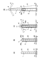
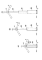
上記課題を解決するための手段として、請求項1に記載した発明に係る風力発電タワーの構築方法は、図1A〜Dに示したように、上下方向にスライド可能に内外に組み合わせた2体の塔体1、2を入れ子式に構築し、外側の塔体2を基礎3に固定し、内側の塔体1の頭部にナセル4、ローターブレード5等の風力発電機器を据え付けるステップと、
前記内側の塔体1を、前記外側の塔体2に反力をとって上昇させ、上昇限度に到達した段階で、前記内側の塔体1の下端部11を前記外側の塔体2の上端部20aに緊結するステップにより風力発電タワーを構築することを特徴とする。
As a means for solving the above-mentioned problem, the construction method of the wind power generation tower according to the invention described in
The
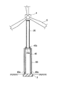
請求項2に記載した発明に係る風力発電タワーの構築方法は、図9〜図14に示したように、上下方向にスライド可能に内外に組み合わせた複数の塔体30、40、50を入れ子式に構築し、最も外側の塔体50を基礎3に固定し、最も内側の塔体30の頭部にナセル4、ローターブレード5等の風力発電機器を据え付けるステップと、
最も内側の塔体30を、その外側に隣接する塔体40に反力をとって上昇させ、上昇限度に到達した段階で、前記内側の塔体30の下端部30aをその外側に隣接する塔体40の上端部40bに緊結し、次いで前記外側の塔体40を更に外側の塔体50に反力をとって上昇させ、上昇限度に到達した段階で、前記外側の塔体40の下端部40aを更に外側の塔体50の上端部50bに緊結する工程を、最も外側の塔体50の内側に隣接する塔体40を上昇させるまで順次行うステップにより風力発電タワーを構築することを特徴とする。
The construction method of the wind power generation tower according to the invention described in
The
請求項3に記載した発明は、請求項1又は2に記載した風力発電タワーの構築方法において、塔体1を上昇させる手段は、その外側に隣接する塔体自体を反力架台としてリフトアップ、又はプッシュアップすることを特徴とする。
The invention described in
請求項4に記載した発明は、請求項1〜3のいずれか一に記載した風力発電タワーの構築方法において、上昇する塔体の外側面と、その外側に隣接する塔体の内側面のいずれか一方にガイドを鉛直方向に設け、他方に前記ガイドに沿ってスライド可能なレールを鉛直方向に設けることを特徴とする。 According to a fourth aspect of the present invention, in the wind power tower construction method according to any one of the first to third aspects, any one of the outer side surface of the rising tower body and the inner side surface of the tower body adjacent to the outer side of the tower body. One of them is provided with a guide in the vertical direction, and the other is provided with a rail that can slide along the guide in the vertical direction.
請求項5に記載した発明は、請求項1〜4のいずれか一に記載した風力発電タワーの構築方法において、塔体を上昇させる際のバランス制御は、塔体周辺に設置したウィンチにより行うことを特徴とする。
The invention described in
請求項6に記載した発明は、請求項1〜5のいずれか一に記載した風力発電タワーの構築方法において、塔体は、プレキャストコンクリート部材を鉛直方向に積み上げて構築することを特徴とする。
The invention described in
請求項7に記載した発明は、請求項1〜6のいずれか一に記載した風力発電タワーの構築方法において、塔体の外形は、寸胴形状、又はテーパー形状とし、水平断面形状は、円形状、又は多角形状とすることを特徴とする。
The invention described in
請求項1〜7に記載した発明に係る風力発電タワーの構築方法によれば、風力発電タワーの構成要素である塔体を、上下方向にスライド可能に内外に組み合わせた入れ子式に構築するので、ナセル及びローターブレード等の風力発電機器の据え付け作業を地上20m〜30m程度の比較的低所で行うことができ、それでいて40m〜120m程度の高さを有する大型化した風力発電タワーを構築することができる。また、前記風力発電機器の据え付け作業を地上20m〜30m程度の比較的低所で行うことができるので、大型クレーンおよび大掛かりな仮設部材が一切不要となり、工期も短縮でき、施工性及び安全性並びに経済性に非常に優れている。さらに、仮設部材等に起因する建設廃棄物も極力少なくして実施できるので、環境性にも優れている。
According to the construction method of the wind power tower according to the invention described in
また、前記風力発電機器が劣化等して取り替える必要が生じたときは、構築時と逆の工程を行い、風力発電機器の取り替え作業をやはり、地上20m〜30m程度の比較的低所でスムーズに行うことができるので、大型クレーンおよび大掛かりな仮設部材は必要とせず、工期も短縮でき、施工性及び安全性並びに経済性に非常に優れている。 In addition, when the wind power generation equipment needs to be replaced due to deterioration or the like, the process reverse to that at the time of construction is performed, and the replacement work of the wind power generation equipment is still smooth in a relatively low place of about 20 m to 30 m above the ground. Since it can be performed, a large crane and a large temporary member are not required, the construction period can be shortened, and the construction workability, safety, and economic efficiency are extremely excellent.
本発明に係る風力発電タワーの構築方法は、上述した発明の効果を奏するべく、以下のように実施される。 The method for constructing a wind power generation tower according to the present invention is implemented as follows in order to achieve the effects of the above-described invention.
図1A〜Dは、請求項1に記載した発明に係る風力発電タワーの構築方法の実施例を段階的に示している。 1A to 1D show stepwise examples of a method for constructing a wind power tower according to the first aspect of the present invention.
この実施例1に係る風力発電タワーの構築方法は、上下方向にスライド可能に内外に組み合わせた2体の塔体1、2を入れ子式に構築し(図1B参照)、外側の塔体2を基礎3に固定し、内側の塔体1の頭部にナセル4、ローターブレード5等の風力発電機器を据え付ける(図1C参照)。次に、前記内側の塔体1を、前記外側の塔体2に反力をとって上昇させ、上昇限度に到達した段階で、前記内側の塔体1の下端部11を前記外側の塔体2の上端部20aに緊結して風力発電タワーを構築する(請求項1記載の発明)。
In the construction method of the wind power generation tower according to the first embodiment, two
具体的に、前記風力発電タワーの構築方法は、先ず、図1Aに示したように、山岳地帯や離島などの強風地帯における風力発電タワーを設置するのに好適な場所に基礎3を構築し、当該基礎3上に、前記内側の塔体(以下適宜、トップタワーと云う。)1を構築する。
Specifically, in the construction method of the wind power tower, first, as shown in FIG. 1A, the
前記トップタワー1は、現場近辺の工場で製作した1体当たり高さ3.0m、外径2.5m、重量150kN程度の円筒形のプレキャストコンクリート部材(以下、PCa部材と云う。)10を複数体(図示例では7体)用意し、1200kN級程度のトラッククレーンを使用して鉛直方向に積み上げて構築している(請求項6記載の発明)。
The
前記PCa部材10同士の接合方式としては種々考えられるが、この実施例1では、図2A、Bに示したような、重ね継ぎ手方式(上下方向に鉄筋10aをラップさせて接合する方式)を採用し、PCa部材10と鉄筋10aとの隙間には、高強度モルタル等のグラウト材(図示省略)を充填して実施している。また、前記トップタワー1の最も下位に位置するPCa部材10の下端部には、リフトアップ用のコンクリート製(或いは鋼製)のベース部材11(外径3.06m)を同心円配置で取り付けている。前記ベース部材11は、リフトアップ時の荷重を均等に分散させる作用を奏する。なお、前記ベース部材11は、前記トップタワー1の下端部を閉塞する円盤状で実施しているが、これに限定されず、前記トップタワー1の下端部の外側に沿ってリング状に設けて実施してもよい。
Various methods of joining the PCa
以上のようにして構築したトップタワー1は、20m程度の高さを有し、アンカーボルト等の仮固定部材(図示省略)を利用して、前記基礎3に仮固定する。
The
なお、前記トップタワー1(PCa部材10)は、寸胴形状で実施しているが、上方に向かって漸次先細状のテーパー形状で実施することもできる。また、水平断面形状は、円形状で実施しているが、多角形状で実施することもできる(請求項7記載の発明)。 In addition, although the said top tower 1 (PCa member 10) is implemented by the size cylinder shape, it can also be implemented by the taper shape of a taper gradually toward upper direction. Moreover, although the horizontal cross-sectional shape is implemented in a circular shape, it can also be implemented in a polygonal shape (the invention according to claim 7).
次に、図1Bと図3に示したように、前記内側の塔体(トップタワー)1を取り囲む形態で、外側の塔体(以下適宜、ボトムタワーと云う。)2を、平面方向から見て前記ベース部材11の外周面に沿って同心円配置で構築する。
Next, as shown in FIG. 1B and FIG. 3, the outer tower body (hereinafter referred to as a bottom tower as appropriate) 2 is viewed from the plane direction in a form surrounding the inner tower body (top tower) 1. Then, it is constructed in a concentric arrangement along the outer peripheral surface of the
前記ボトムタワー2は、現場近辺の工場で製作した1体当たり高さ2.5m、外径3.8m、重量150kN程度の円筒形のPCa部材20を複数体(図示例では8体)用意し、1200kN級程度のトラッククレーンを使用して、前記重ね継ぎ手方式により、鉛直方向に積み上げて構築している。また、前記ボトムタワー2(高さ20m程度)の最も下位に位置するPCa部材20の下端部は、所謂PC圧着方式により、基礎3と緊結して固定している。さらに、前記ボトムタワー2の最も上位に位置するPCa部材20の上端部には、その内周面に、リフトアップ用の油圧ジャッキ6を設置するための突出部(架台)20aが、ほぼ等間隔にバランス良く3箇所設けられている。この実施例1に係る前記突出部20aは、予めPCa部材20と一体成形され、前記トップタワー1の外周面に届く程度の水平長さを有する。なお、前記突出部20aは、3箇所に限定されるものではなく、4箇所以上にバランス良く設けて実施することもできるし、前記PCa部材20の内周面全面にリング状に設けて実施することもできる。
The
かくして、前記トップタワー1と前記ボトムタワー2は、上下方向にスライド可能に内外に組み合わせた入れ子式に構築されると共に、前記トップタワー1の下端部に設けたベース部材11と、前記ボトムタワー2の上端部に設けた突出部20aとがガイド的な働きをして水平変位を拘束し、安定した状態でトップタワー1を上昇させることができる構造となるのである。
Thus, the
次に、図1Cに示したように、前記ボトムタワー2の突出部20aの上面にリフトアップ用の油圧ジャッキ(センターホールジャッキ)6をバランスよく所要の台数(本実施例では3台)設置する。そして、各油圧ジャッキ6…と、リフトアップするトップタワー1のベース部材11とを、前記トップタワー1の外周面とボトムタワー2の内周面との間に鉛直方向に吊り下げされたワイヤロープ、PC鋼より線、ロッド等の揚重用連結材7で繋ぐ。
Next, as shown in FIG. 1C, a required number (three in this embodiment) of lift-up hydraulic jacks (center hole jacks) 6 are installed on the upper surface of the protruding
前記揚重用連結材7は、その上端部を、前記突出部20aに予め設けた通し孔及び前記油圧ジャッキ6へ通し当該油圧ジャッキ6を利用して固定し、その下端部を前記ベース部材11に予め設けた通し孔へ鉛直方向に通し、定着ナット等の掛け止め部材を利用して前記ベース部材11に固定する。
The
次に、図1Cに示したように、前記トップタワー1の頭部にナセル4、ローターブレード5等の風力発電機器をクレーン(図示省略)を利用して据え付ける。
Next, as shown in FIG. 1C, wind power generators such as a
この実施例1によると、通常、1000kNは超える大重量の風力発電機器を、前記トップタワー1の高さ、即ち20m程度の高さ揚重すれば足りるので、大型のクレーンを使用する必要は一切ない。ちなみに、前記ローターブレード5の1枚当たりのブレード長は、構築する風力発電タワーの高さの1/2程度が好適とされ、この実施例1では、20mの長さのブレードが使用されている。図1Cに示した状態でローターブレード5を仮固定すると、前記ブレード長の鉛直高さは10m(20m×cos60°)程度となり、少なくとも地上10m以上の高さで据付ける必要がある。一方、前記トップタワー1の高さは20m程度である。よって、前記ローターブレード5は、地面に衝突する等の支障もなく安全に据え付けることができるのである。
According to the first embodiment, it is usually sufficient to lift a heavy wind power generation apparatus having a heavy weight exceeding 1000 kN to the height of the
以下に、前記トップタワー1を上昇させる工程を説明する。
Below, the process of raising the
前記ナセル4、ローターブレード5等の風力発電機器を据え付け、入れ子式に構築したトップタワー1及びボトムタワー2について、図1Dに示したように、前記トップタワー1を、前記ボトムタワー2の突出部20a上に設置した油圧ジャッキ6を利用して、所定の高さまでリフトアップする作業を開始する(請求項3記載の発明)。
As shown in FIG. 1D, the
ここで、前記風力発電機器を据え付けたトップタワー1の重心位置は、構築する風力発電タワーの重心位置とは一致せず、リフトアップ時に偏心荷重が生じる。この偏心荷重を相殺してリフトアップをスムーズに行うために、バランス制御用のステーワイヤー8を使用することが安全上好ましい。このステーワイヤー8は、ウィンチ9を用い、リフトアップ用の油圧ジャッキ6と連動させながら制御する。また、前記ウィンチ9(ステーワイヤー8)は、必要に応じて1箇所から複数箇所設置して実施する(請求項5記載の発明)。
Here, the position of the center of gravity of the
かくして、前記突出部20a上の油圧ジャッキ6を作動させて、前記揚重用連結材7及びこれに吊り支持されたベース部材11を徐々に上昇移動(リフトアップ)させて前記トップタワー1を上昇させる。前記トップタワー1は、ガイド的な働きをし水平変位を拘束する前記ベース部材11及び前記突出部20aと、バランス制御する前記ステーワイヤー8及び前記ウィンチ9により、安定した状態で徐々に上昇させることができる。
Thus, the
また、前記トップタワー1を更に安定した状態で(特には、無回転のまま)上昇させるべく、図4に示したように、前記トップタワー1の外側面に、水平断面がコ字形状のガイド1aを鉛直方向に設け、前記ボトムタワー2の内側面に前記ガイド1aに沿ってスライド可能なレール2aを鉛直方向に設けて実施することが好ましい。勿論、前記トップタワー1の外側面にレール2aを設け、前記ボトムタワー2の内側面にガイド1を設けて実施することもできる。なお、前記ガイド1a及びレール2aの水平断面形状は図示例に限定されるものではなく、前記トップタワー1を無回転のままボトムタワー2に沿って上昇させることができる形状であればよい(請求項4記載の発明)。
Further, in order to raise the
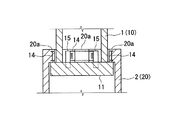
前記油圧ジャッキ6によるリフトアップ作業は、前記トップタワー1のベース部材11の上面が、前記ボトムタワー2の突出部20aの下面に当接するまで行う。前記油圧ジャッキ6によるリフトアップ作業が終了した後は、図5A、Bに示したように、前記油圧ジャッキ6から緊結用鋼材12へ徐々にトップタワー1の荷重を盛り替え、前記トップタワー1のベース部材11とボトムタワー2の突出部20aとの緊結作業を行い、かくして、高さが40m程度の風力発電タワーの構築作業を完了する。
The lift-up operation by the
具体的に、この実施例1に係る緊結作業は、前記突出部20aとベース部材11に予め穿設しておいた鉛直方向のボルト孔を一致させ、当該ボルト孔に高力ボルト12aを挿入し、ナット12bで締め付け固定し、必要に応じて、底面部の前記ベース部材11と側面部の前記PCa部材20とが形成する凹部にコンクリートを打設することにより、前記トップタワー1とボトムタワー2とを構造的に一体化している。ちなみに、前記突出部20a及びベース部材11に設けた前記ボルト孔の一部は、前記揚重用連結材7の通し孔として使用される。
Specifically, in the tightening work according to the first embodiment, the projecting
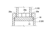
前記緊結手段は勿論これに限定されず、前記トップタワー1とボトムタワー2とを構造的に一体化できる方法であればよい。例えば、図6A、Bに示したように、前記ベース部材11と突出部20aの双方に埋め込まれた縦筋13aと前記突出部20aを貫通する横筋13bとから成る緊結用鉄筋13にコンクリートを打設して、前記トップタワー1とボトムタワー2とを構造的に一体化して実施してもよい。また、図7に示したように、前記突出部20aに水平方向に貫通するI形鋼(又はH形鋼)14を設け、前記ベース部材11に立設する鋼管15と溶接及びボルト等の接合手段で一体化して実施してもよい。さらに、図8に示したように、前記ベース部材11と前記PCa部材20に予め、ベース部材11の上面が、前記ボトムタワー2の突出部20aの下面に当接する際に一致するボルト孔16を水平方向に穿設しておき、前記ボルト孔16に鋼材(図示省略)を挿入してロックする態様で緊結し、必要に応じて、底面部の前記ベース部材11と側面部の前記PCa部材20とが形成する凹部にコンクリートを打設することにより、前記トップタワー1とボトムタワー2とを構造的に一体化して実施してもよい。
Of course, the fastening means is not limited to this, and any method can be used as long as the
以上説明したように、上記実施例1によれば、風力発電タワーの構成要素である塔体(トップタワー1及びボトムタワー2)を、上下方向にスライド可能に内外に組み合わせた入れ子式に構築するので、ナセル4及びローターブレード5等の風力発電機器の据え付け作業を地上20m程度の比較的低所で行うことができ、それでいて40m程度の高さを有する風力発電タワーを構築することができる。また、前記風力発電機器の据え付け作業を地上20m程度の比較的低所で行うことができるので、大型クレーンおよび大掛かりな仮設部材が一切不要となり、工期も短縮でき、施工性及び安全性並びに経済性に非常に優れている。さらに、仮設部材等に起因する建設廃棄物も極力少なくして実施できるので、環境性にも優れている。
As described above, according to the first embodiment, the towers (the
また、前記風力発電機器が劣化等して取り替える必要が生じたときは、構築時と逆の工程を行う。即ち、前記ベース部材11とPCa部材20との緊結状態を解除し、前記トップタワー1を地上に到達するまで下降させた後に取り替え作業を行う。よって、風力発電機器の取り替え作業は、やはり地上20m程度の比較的低所で行うことができるので、大型クレーンおよび大掛かりな仮設部材は必要とせず、工期も短縮でき、施工性及び安全性並びに経済性に非常に優れている。
Further, when the wind power generation equipment needs to be replaced due to deterioration or the like, the reverse process of the construction is performed. That is, the tightening state between the
なお、この実施例1では、前記トップタワー1を、前記ボトムタワー2の上端部に反力をとりリフトアップする手段で上昇させているが、これに限定されず、前記ベース部材11の下面部の外周縁部に油圧ジャッキを設置し、前記ボトムタワー2の内側面に設けた反力ピースを利用してプッシュアップする手段で上昇させることもできる(請求項3記載の発明)。また、前記トップタワー1及びボトムタワー2はコンクリート製で実施しているが、これに限定されず、鉄筋コンクリート製、鉄骨コンクリート製、コンクリート充填鋼管などタワーを構築できるものであれば、材質は特に限定されない。さらに、前記トップタワー1及びボトムタワー2は所謂めくら壁で実施しているが、開口部を設けて実施することも勿論できる。以下の実施例2についても同様の技術的思想とする。
In the first embodiment, the
図9A〜Cは、請求項2に記載した発明に係る風力発電タワーの構築方法の実施例を段階的に示している。請求項2に係る風力発電タワーの構築方法は、上記した請求項1と比して、風力発電タワーの構成要素である塔体を複数(具体的には3体以上)用いて実施することが主に相違する。
9A to 9C show step by step an embodiment of a method for constructing a wind power tower according to the invention described in
すなわち、この実施例2に係る風力発電タワーの構築方法は、上下方向にスライド可能に内外に組み合わせた複数(この実施例では3体)の塔体30、40、50を入れ子式に構築し(図9A参照)、最も外側の塔体50を基礎3に固定し、最も内側の塔体30の頭部にナセル4、ローターブレード5等の風力発電機器を据え付ける(図9A参照)。次に、前記最も内側の塔体30を、その外側に隣接する塔体40に反力をとって上昇させ、上昇限度に到達した段階で、前記内側の塔体30の下端部30aをその外側に隣接する塔体40の上端部40bに緊結し、次いで前記外側の塔体40を更に外側の塔体50に反力をとって上昇させ、上昇限度に到達した段階で、前記外側の塔体40の下端部40aを更に外側の塔体50の上端部50bに緊結する工程を、最も外側の塔体50の内側に隣接する塔体40を上昇させるまで順次行うことにより、風力発電タワーを構築する。なお、この実施例2では3体の塔体で実施しているが、勿論4体以上で実施することもできる。(請求項2記載の発明)。
That is, the construction method of the wind power generation tower according to the second embodiment is constructed by nesting a plurality of (three in this embodiment)
具体的に、前記風力発電タワーの構築方法は、先ず、図9Aに示したように、山岳地帯や離島などの強風地帯における風力発電タワーを設置するのに好適な場所に基礎3を構築し、当該基礎3上に、前記最も内側の塔体(以下適宜、トップタワーと云う。)30を構築する。
Specifically, in the construction method of the wind power generation tower, first, as shown in FIG. 9A, the
前記トップタワー30は、現場近辺の工場で製作した1体当たり高さ3.0m、外径2.5m、重量150kN程度の円筒形のPCa部材を複数体(本実施例では10体)用意し、1200kN級程度のトラッククレーンを使用して鉛直方向に積み上げて構築している(請求項6記載の発明)。前記PCa部材同士の接合方式としては種々考えられるが、この実施例2では、上記実施例1と同様に、重ね継ぎ手方式を採用し、PCa部材と鉄筋との隙間には、高強度モルタル等のグラウト材を充填して実施している。また、前記トップタワー30の最も下位に位置するPCa部材の下端部には、図10Aに示したように、上記実施例1と同様に、ベース部材30a(外径3.06m)を同心円配置で取り付けている。なお、前記ベース部材30aは、前記トップタワー30の下端部を閉塞する円盤状で実施しているが、これに限定されず、前記トップタワー30の下端部の外側に沿ってリング状に設けて実施してもよい。
The
このようにして構築したトップタワー30は、30m程度の高さを有し、アンカーボルト等の仮固定部材(図示省略)を利用して、前記基礎3に仮固定する。
The
次に、図10A、Bに示したように、前記最も内側の塔体(トップタワー)30を取り囲む形態で、外側の塔体(以下適宜、ミドルタワーと云う。)40を、平面方向から見て前記トップタワー30のベース部材30aの外周面に沿って同心円配置で構築する。
Next, as shown in FIGS. 10A and 10B, an outer tower body (hereinafter, referred to as a middle tower as appropriate) 40 is seen from a plane direction in a form surrounding the innermost tower body (top tower) 30. Thus, the
前記ミドルタワー40は、現場近辺の工場で製作した1体当たり高さ3.0m、外径3.8m程度の円筒形のPCa部材を複数体(本実施例では10体)用意し、1200kN級のトラッククレーンを使用して、前記重ね継ぎ手方式により、鉛直方向に積み上げて構築している(請求項5記載の発明)。また、前記ミドルタワー40の最も下位に位置するPCa部材の下端部には、図10Aに示したように、その外側に沿って、リング状のベース部材40aを同心円配置で取り付けている。さらに、前記ミドルタワー40の最も上位に位置するPCa部材20の上端部には、上記実施例1と同様に、図10Aに示したように、その内周面に、リフトアップ用の油圧ジャッキ6を設置するための突出部(架台)40bが、ほぼ等間隔にバランス良く3箇所設けられている(図3も参照)。前記突出部40bは、予めPCa部材と一体成形され、前記トップタワー30の外周面に届く程度の水平長さを有する。なお、前記突出部40bは、3箇所に限定されるものではなく、4箇所以上設けて実施することもできるし、PCa部材の内周面全面にリング状に設けて実施することもできる。
The
このようにして構築したミドルタワー40は、30m程度の高さを有し、アンカーボルト等の仮固定部材(図示省略)を利用して、前記基礎3に仮固定する。
The
次に、図10A、Bに示したように、前記ミドルタワー40を取り囲む形態で、外側の塔体(以下適宜、ボトムタワーと云う。)50を、平面方向から見て前記ミドルタワー40のベース部材40aの外周面に沿って同心円配置で構築する。
Next, as shown in FIGS. 10A and 10B, an outer tower body (hereinafter, referred to as a bottom tower as appropriate) 50 in a form surrounding the
前記ボトムタワー50は、現場近辺の工場で製作した1体当たり高さ3.0m、外径5.1m程度の円筒形のPCa部材を複数体(本実施例では10体)用意し、1200kN級程度のトラッククレーンを使用して、前記重ね継ぎ手方式により、鉛直方向に積み上げて構築している(請求項6記載の発明)。また、前記ボトムタワー50の最も下位に位置するPCa部材の下端部は、所謂PC圧着方式により、基礎3と緊結して固定している。さらに、前記ボトムタワー50の最も上位に位置するPCa部材の上端部には、図10Aに示したように、その内周面に沿って、リフトアップ用の油圧ジャッキを設置するための突出部(架台)50bが、ほぼ等間隔にバランス良く3箇所設けられている(図3も参照)。前記突出部50bは、予めPCa部材と一体成形され、前記ミドルタワー40の外周面に届く程度の水平長さを有する。なお、前記突出部50bは、3箇所に限定されるものではなく、4箇所以上設けて実施することもできるし、PCa部材20の内周面全面にリング状に設けて実施することもできる。
The
かくして、前記トップタワー30とミドルタワー40とボトムタワー50は、上下方向にスライド可能に内外に組み合わせた入れ子式に構築されると共に、前記ベース部材30a、40aと、突出部40b、50bとが、ガイド的な働きをして水平変位を拘束し、安定した状態でトップタワー30及びミドルタワー40を上昇させることができる構造となるのである。なお、前記トップタワー30とミドルタワー40とボトムタワー50はそれぞれ、寸胴形状で実施しているが、上方に向かって漸次先細状のテーパー形状で実施することもできるし、水平断面形状は、円形状で実施しているが、多角形状で実施することもできる(請求項7記載の発明)。
Thus, the
次に、図10Aに示したように、前記ミドルタワー40の突出部40bの上面にリフトアップ用の油圧ジャッキ(センターホールジャッキ)6を、上記実施例1と同様に、バランスよく所要の台数(本実施例では3台)設置する。そして、各油圧ジャッキ6…と、リフトアップするトップタワー30のベース部材30aとを、前記トップタワー30の外周面とミドルタワー40の内周面との間に鉛直方向に吊り下げされたワイヤロープ、PC鋼より線、ロッド等の揚重用連結材7で繋ぐ。
Next, as shown in FIG. 10A, a lift-up hydraulic jack (center hole jack) 6 is provided on the upper surface of the protruding
前記揚重用連結材7は、その上端部を前記突出部40bに予め設けた通し孔及び前記油圧ジャッキ6へ通し当該油圧ジャッキ6を利用して固定し、その下端部を前記ベース部材30aへ予め設けた通し孔へ鉛直方向に通し、定着ナット等の掛け止め部材を利用して前記ベース部材30aに固定する。
The
次に、前記トップタワー30の頭部にナセル4、ローターブレード5等の風力発電機器をクレーン(図示省略)を利用して据え付ける。
Next, wind power generators such as the
この実施例2によると、通常、1000kNは超える大重量の風力発電機器を、前記トップタワー30の高さ、即ち30m程度の高さ揚重すれば足りるので、大型のクレーンを使用する必要は一切ない。ちなみに、前記ローターブレード5の1枚当たりのブレード長は、構築する風力発電タワーの高さの1/2程度が好適とされ、この実施例2では、45mの長さのブレードが使用されている。図9に示した状態でローターブレード5を仮固定すると、前記ブレード長の鉛直高さは22.5m(45m×cos60°)程度となり、少なくとも地上22.5m以上の高さで据付ける必要がある。一方、前記トップタワー30の高さは30m程度である。よって、前記ローターブレード5は、地面に衝突する等の支障もなく安全に据え付けることができるのである。
According to the second embodiment, it is usually sufficient to lift a heavy-weight wind power generation device having a weight of over 1000 kN to the height of the
以下に、前記トップタワー30とミドルタワー40を上昇させる工程を順に説明する。
Hereinafter, the steps of raising the
前記ナセル4、ローターブレード5等の風力発電機器を据え付け、入れ子式に構築したトップタワー30及びミドルタワー40並びにボトムタワー50について、図11に示したように、前記トップタワー30を、前記ミドルタワー40の突出部40b上に設置した油圧ジャッキ6を利用して、所定の高さまでリフトアップする作業を開始する(請求項3記載の発明)。
As shown in FIG. 11, the
ここで、バランス制御用のステーワイヤー8とウィンチ9を使用することは、上記実施例1で説明した通りである(請求項5記載の発明)。
Here, the use of the
かくして、前記突出部40b上の油圧ジャッキ6を作動させて、前記揚重用連結材7及びこれに吊り支持されたベース部材30aを徐々に上昇移動(リフトアップ)させて前記トップタワー30を上昇させる。前記トップタワー30は、ガイド的な働きをし水平変位を拘束する前記ベース部材30a及び突出部40bと、バランス制御する前記ステーワイヤー8及び前記ウィンチ9により、安定した状態で徐々に上昇させることができる。
Thus, by operating the
また、前記トップタワー30を安定した状態で(特には、無回転のまま)上昇させるべく、前記トップタワー30の外側面にガイド1aを鉛直方向に設け、前記ミドルタワー40の内側面に前記ガイド1aに沿ってスライド可能なレール2aを鉛直方向に設けて実施することが好ましいのは、上記実施例1で説明した通りである(図4参照、請求項4記載の発明)。
Further, in order to raise the
前記油圧ジャッキ6によるリフトアップ作業は、前記トップタワー30のベース部材30aの上面が、前記ミドルタワー40の突出部40bの下面に当接するまで行う。前記油圧ジャッキ6によるリフトアップ作業が終了した後は、図12に示したように、上記実施例1で種々説明した手段(図5〜図8参照)で、前記トップタワー30のベース部材30aとミドルタワー40の突出部40bとの緊結作業を行う。
The lift-up operation by the
次に、図13に示したように、前記ミドルタワー40を、前記ボトムタワー50の突出部50b上に設置した油圧ジャッキ6を利用して、所定の高さまでリフトアップする作業を開始する(請求項3記載の発明)。
Next, as shown in FIG. 13, the
前記油圧ジャッキ6は、前記ボトムタワー50の突出部50bの上面に、上記実施例1と同様に、バランスよく所要の台数(本実施例では3台)設置する。そして、各油圧ジャッキ6…と、リフトアップするミドルタワー40のベース部材40aとを、前記ミドルタワー40の外周面とボトムタワー50の内周面との間に鉛直方向に吊り下げされたワイヤロープ、PC鋼より線、ロッド等の揚重用連結材7で繋ぐ。
The required number of hydraulic jacks 6 (three in this embodiment) are installed on the upper surface of the protruding
前記揚重用連結材7は、その上端部を前記突出部50bに予め設けた通し孔及び前記油圧ジャッキ6へ通し当該油圧ジャッキ6を利用して固定し、その下端部を前記ベース部材40aへ予め設けた通し孔へ鉛直方向に通し、定着ナット等の掛け止め部材を利用して前記ベース部材40aに固定する。
The
バランス制御用のステーワイヤー8とウィンチ9を使用することは、上記実施例1で説明した通りである(請求項5記載の発明)。
The use of the
かくして、前記突出部50b上の油圧ジャッキ6を作動させて、前記揚重用連結材7及びこれに吊り支持されたベース部材40aを徐々に上昇移動(リフトアップ)させて前記ミドルタワー40を上昇させる。前記ミドルタワー40は、ガイド的な働きをし水平変位を拘束する前記ベース部材40a及び突出部50bと、バランス制御する前記ステーワイヤー8及び前記ウィンチ9により、安定した状態で徐々に上昇させることができる。
Thus, by operating the
また、前記ミドルタワー40を安定した状態で(特には、無回転のまま)上昇させるべく、前記ミドルタワー40の外側面にガイド1aを鉛直方向に設け、前記ボトムタワー50の内側面に前記ガイド1aに沿ってスライド可能なレール2aを鉛直方向に設けて実施することが好ましいのは、上記実施例1で説明した通りである(図4参照、請求項4記載の発明)。
Further, in order to raise the
前記油圧ジャッキ6によるリフトアップ作業は、前記ミドルタワー40のベース部材40aの上面が、前記ボトムタワー50の突出部50bの下面に当接するまで行う。前記油圧ジャッキ6によるリフトアップ作業が終了した後は、図14に示したように、上記実施例1で種々説明した手段(図5〜図8参照)で、前記ミドルタワー40のベース部材40aとボトムタワー50の突出部50bとの緊結作業を行い、かくして、高さが90m程度の風力発電タワーの構築作業を完了する。
The lift-up operation by the
以上説明したように、上記実施例2によれば、風力発電タワーの構成要素である塔体(トップタワー30及びミドルタワー40並びにボトムタワー50)を、上下方向にスライド可能に内外に組み合わせた入れ子式に構築するので、ナセル4及びローターブレード5等の風力発電機器の据え付け作業を地上30m程度の比較的低所で行うことができ、それでいて90m程度の高さを有する風力発電タワーを構築することができる。また、前記風力発電機器の据え付け作業を地上30m程度の比較的低所で行うことができるので、大型クレーンおよび大掛かりな仮設部材が一切不要となり、工期も短縮でき、施工性及び安全性並びに経済性に非常に優れている。さらに、仮設部材等に起因する建設廃棄物も極力少なくして実施できるので、環境性にも優れている。
As described above, according to the second embodiment, the tower body (the
また、前記風力発電機器が劣化等して取り替える必要が生じたときは、構築時と逆の工程を行う。即ち、前記ミドルタワー40のベース部材40aとボトムタワー50の突出部50bとの緊結状態を解除し、当該ミドルタワー40を地上に到達するまで下降させ、次いで前記トップタワー30のベース部材30aとミドルタワー40の突出部40bとの緊結状態を解除し、当該トップタワー30を地上に到達するまで下降させた後に取り替え作業を行う。よって、風力発電機器の取り替え作業は、やはり地上30m程度の比較的低所で行うことができるので、大型クレーンおよび大掛かりな仮設部材は必要とせず、工期も短縮でき、施工性及び安全性並びに経済性に非常に優れている。
Further, when the wind power generation equipment needs to be replaced due to deterioration or the like, the reverse process of the construction is performed. That is, the tight state of the
以上に実施例を図面に基づいて説明したが、本発明は、図示例の実施例の限りではなく、その技術的思想を逸脱しない範囲において、当業者が通常に行う設計変更、応用のバリエーションの範囲を含むことを念のために言及する。 Although the embodiments have been described with reference to the drawings, the present invention is not limited to the embodiments shown in the drawings, and design modifications and application variations that are usually performed by those skilled in the art are within the scope not departing from the technical idea thereof. Note that it includes the range.
例えば、120m程度の高さの風力発電タワーを構築する場合には、高さ30m程度の塔体を4体、入れ子式に構築し、上記説明したように、内側の塔体を、外側に隣接する塔体に反力をとって上昇させ、上昇限度に到達した段階で、前記内側の塔体の下端部をその外側に隣接する塔体の上端部に緊結する工程を、最も内側の塔体から最も外側の塔体へ順次行うのである。前記塔体の高さは1体当たり20m〜30m程度が好ましいがこれに限定されるものではなく、塔体の個数も5体以上でも実施することができる。 For example, when constructing a wind power generation tower with a height of about 120 m, four towers with a height of about 30 m are built in a nested manner, and as described above, the inner tower is adjacent to the outside. A step of tightening the lower end portion of the inner tower body to the upper end portion of the tower body adjacent to the outer side of the inner tower body when the rising limit is reached. To the outermost tower. The height of the tower is preferably about 20 to 30 m per one body, but is not limited to this, and the number of towers can be 5 or more.
また、ローターブレード5の地上高さが、1体の塔体(トップタワー)の高さより高い場合、例えば、ローターブレード5の長さが50mで、地上高さが25m(50m×cos60°)の場合に、トップタワーの高さが20mの場合には、当該トップタワーを据え付けに必要な高さ(25m程度)までリフトアップ又はプッシュアップして据え付け作業を行い、しかる後、風力発電タワーの構築を進めるのである。
When the ground height of the
1 トップタワー
1a ガイド
2 ボトムタワー
2a レール
3 基礎
4 ナセル(発電機本体)
5 ローターブレード
6 油圧ジャッキ(センターホールジャッキ)
7 揚重用連結材
8 ステーワイヤー
9 ウィンチ
10 プレキャストコンクリート部材(PCa部材)
10a 鉄筋
11 ベース部材
12 緊結用鋼材
12a 高力ボルト
12b ナット
13 緊結用鉄筋
13a 縦筋
13b 横筋
14 I形鋼
15 鋼管
16 ボルト孔
20 プレキャストコンクリート部材(PCa部材)
20a 突出部
30 トップタワー
40 ミドルタワー
50 ボトムタワー
30a ベース部材
40a ベース部材
40b 突出部
50b 突出部
1
5
7 Connecting material for lifting 8
Claims (7)
前記内側の塔体を、前記外側の塔体に反力をとって上昇させ、上昇限度に到達した段階で、前記内側の塔体の下端部を前記外側の塔体の上端部に緊結するステップにより風力発電タワーを構築することを特徴とする、風力発電タワーの構築方法。 Two towers that are slidable in the vertical direction are built in a nested manner, the outer tower is fixed to the foundation, and wind turbine generators such as nacelles and rotor blades are installed on the head of the inner tower. Installation steps,
The inner tower is lifted by reaction force against the outer tower, and when the upper limit is reached, the lower end of the inner tower is fastened to the upper end of the outer tower. A method for constructing a wind power generation tower, characterized in that a wind power generation tower is constructed by the method described above.
最も内側の塔体を、その外側に隣接する塔体に反力をとって上昇させ、上昇限度に到達した段階で、前記内側の塔体の下端部をその外側に隣接する塔体の上端部に緊結し、次いで前記外側の塔体を更に外側の塔体に反力をとって上昇させ、上昇限度に到達した段階で、前記外側の塔体の下端部を更に外側の塔体の上端部に緊結する工程を、最も外側の塔体の内側に隣接する塔体を上昇させるまで順次行うステップにより風力発電タワーを構築することを特徴とする、風力発電タワーの構築方法。 A plurality of towers combined inside and outside to be slidable in the vertical direction are constructed in a nested manner, the outermost tower is fixed to the foundation, and wind turbine generators such as nacelles and rotor blades are mounted on the head of the innermost tower. Steps to install
The innermost tower is lifted by reaction with the tower adjacent to the outer side, and when the upper limit is reached, the lower end of the inner tower is moved to the upper end of the tower adjacent to the outer side. Then, the outer tower body is raised against the outer tower body by a reaction force, and when the rising limit is reached, the lower end portion of the outer tower body is replaced with the upper end portion of the outer tower body. The wind power generation tower construction method is characterized in that the wind power generation tower is constructed by the step of sequentially performing the step of tightening to the inside of the outermost tower body until the adjacent tower body is raised.
Priority Applications (1)
| Application Number | Priority Date | Filing Date | Title |
|---|---|---|---|
| JP2005258766A JP4701047B2 (en) | 2005-09-07 | 2005-09-07 | Wind power tower construction method |
Applications Claiming Priority (1)
| Application Number | Priority Date | Filing Date | Title |
|---|---|---|---|
| JP2005258766A JP4701047B2 (en) | 2005-09-07 | 2005-09-07 | Wind power tower construction method |
Publications (2)
| Publication Number | Publication Date |
|---|---|
| JP2007071097A true JP2007071097A (en) | 2007-03-22 |
| JP4701047B2 JP4701047B2 (en) | 2011-06-15 |
Family
ID=37932777
Family Applications (1)
| Application Number | Title | Priority Date | Filing Date |
|---|---|---|---|
| JP2005258766A Expired - Fee Related JP4701047B2 (en) | 2005-09-07 | 2005-09-07 | Wind power tower construction method |
Country Status (1)
| Country | Link |
|---|---|
| JP (1) | JP4701047B2 (en) |
Cited By (20)
| Publication number | Priority date | Publication date | Assignee | Title |
|---|---|---|---|---|
| JP2009018671A (en) * | 2007-07-11 | 2009-01-29 | Penta Ocean Construction Co Ltd | Spar-type floating body structure for wind power generation on the ocean and manufacturing method of the same |
| JP2009248792A (en) * | 2008-04-08 | 2009-10-29 | Penta Ocean Construction Co Ltd | Spar-type floating body structure for wind power generation on ocean, manufacturing method of the same, and installation method of the same |
| CN101825063A (en) * | 2010-04-21 | 2010-09-08 | 广西银河艾万迪斯风力发电有限公司 | Fast application system for temporary electricity utilization in wind driven generation field |
| CN101832237A (en) * | 2010-06-04 | 2010-09-15 | 西安交通大学 | Pylon structure of wind power generator |
| WO2010110330A1 (en) * | 2009-03-24 | 2010-09-30 | 戸田建設株式会社 | Offshore wind power generator and construction method thereof |
| WO2010110329A1 (en) * | 2009-03-24 | 2010-09-30 | 戸田建設株式会社 | Offshore wind power plant and construction method thereof |
| WO2010129642A2 (en) * | 2009-05-07 | 2010-11-11 | Southworth George L | Method for building wind turbine tower |
| KR101059442B1 (en) | 2009-02-12 | 2011-08-25 | 주식회사 필엔지 | Wind power generator |
| JP2011220102A (en) * | 2010-04-06 | 2011-11-04 | Soletanche Freyssinet | Construction method of hybrid-type tower for wind generator |
| JP2012533008A (en) * | 2009-07-13 | 2012-12-20 | ファウ・エス・エル・インターナツイオナール・アクチエンゲゼルシヤフト | Telescopic tower assembly and method |
| KR101428329B1 (en) * | 2012-12-27 | 2014-08-08 | 주식회사 포스코 | Wind turbine and installation apparatus thereof |
| KR101461146B1 (en) * | 2013-10-15 | 2014-11-20 | 삼성물산 주식회사 | A wind power generator on the sea equiped with retractile tower and it's installing method |
| KR101509666B1 (en) | 2014-04-10 | 2015-04-07 | 주식회사 대하 | constructing apparatus for offshore wind power turbine and construction method thereof |
| CN105035939A (en) * | 2011-01-26 | 2015-11-11 | 乌本产权有限公司 | Method and device for erecting a tower for a wind energy plant |
| KR101692284B1 (en) * | 2015-07-21 | 2017-01-03 | 주식회사 웨스텍 | Portable wind power generation apparatus |
| JP2018016302A (en) * | 2016-07-13 | 2018-02-01 | 戸田建設株式会社 | Offshore wind power generation facility and installation method of the same |
| CN113606094A (en) * | 2021-08-17 | 2021-11-05 | 上海电气风电集团股份有限公司 | Tower section of thick bamboo subassembly and concatenation formula tower section of thick bamboo |
| KR102361508B1 (en) * | 2020-12-14 | 2022-02-14 | 김도영 | Wind power generator |
| WO2023097991A1 (en) * | 2022-03-02 | 2023-06-08 | 武汉釜硕新能源科技有限公司 | Novel wind power generation tower and construction method therefor |
| CN117189462A (en) * | 2023-02-17 | 2023-12-08 | 清天新能源(北京)有限公司 | Novel wind driven generator |
Citations (5)
| Publication number | Priority date | Publication date | Assignee | Title |
|---|---|---|---|---|
| JPS5692370A (en) * | 1979-12-25 | 1981-07-27 | Toshiba Corp | Wind power generation device |
| JPS623176A (en) * | 1985-06-29 | 1987-01-09 | Yamaha Motor Co Ltd | Slidable wind-power generator turning up and down apparatus |
| JPH01190883A (en) * | 1988-01-27 | 1989-07-31 | Ohbayashi Corp | Lift up or down method |
| JP2002122066A (en) * | 2000-10-16 | 2002-04-26 | Ps Corp | Wind power generating tower |
| JP2002266434A (en) * | 2001-03-08 | 2002-09-18 | Mitsubishi Heavy Ind Ltd | Method of constructing cable dome |
-
2005
- 2005-09-07 JP JP2005258766A patent/JP4701047B2/en not_active Expired - Fee Related
Patent Citations (5)
| Publication number | Priority date | Publication date | Assignee | Title |
|---|---|---|---|---|
| JPS5692370A (en) * | 1979-12-25 | 1981-07-27 | Toshiba Corp | Wind power generation device |
| JPS623176A (en) * | 1985-06-29 | 1987-01-09 | Yamaha Motor Co Ltd | Slidable wind-power generator turning up and down apparatus |
| JPH01190883A (en) * | 1988-01-27 | 1989-07-31 | Ohbayashi Corp | Lift up or down method |
| JP2002122066A (en) * | 2000-10-16 | 2002-04-26 | Ps Corp | Wind power generating tower |
| JP2002266434A (en) * | 2001-03-08 | 2002-09-18 | Mitsubishi Heavy Ind Ltd | Method of constructing cable dome |
Cited By (27)
| Publication number | Priority date | Publication date | Assignee | Title |
|---|---|---|---|---|
| JP2009018671A (en) * | 2007-07-11 | 2009-01-29 | Penta Ocean Construction Co Ltd | Spar-type floating body structure for wind power generation on the ocean and manufacturing method of the same |
| JP2009248792A (en) * | 2008-04-08 | 2009-10-29 | Penta Ocean Construction Co Ltd | Spar-type floating body structure for wind power generation on ocean, manufacturing method of the same, and installation method of the same |
| KR101059442B1 (en) | 2009-02-12 | 2011-08-25 | 주식회사 필엔지 | Wind power generator |
| WO2010110330A1 (en) * | 2009-03-24 | 2010-09-30 | 戸田建設株式会社 | Offshore wind power generator and construction method thereof |
| WO2010110329A1 (en) * | 2009-03-24 | 2010-09-30 | 戸田建設株式会社 | Offshore wind power plant and construction method thereof |
| JP2010223113A (en) * | 2009-03-24 | 2010-10-07 | Toda Constr Co Ltd | Wind power generation facility on the ocean, and method for constructing the same |
| JP2010223114A (en) * | 2009-03-24 | 2010-10-07 | Toda Constr Co Ltd | Wind power generation facility on the ocean, and method for constructing the same |
| WO2010129642A3 (en) * | 2009-05-07 | 2011-03-03 | Southworth George L | Method for building wind turbine tower |
| WO2010129642A2 (en) * | 2009-05-07 | 2010-11-11 | Southworth George L | Method for building wind turbine tower |
| JP2012533008A (en) * | 2009-07-13 | 2012-12-20 | ファウ・エス・エル・インターナツイオナール・アクチエンゲゼルシヤフト | Telescopic tower assembly and method |
| EP2454427B1 (en) * | 2009-07-13 | 2017-02-15 | VSL International AG | Telescopic tower assembly and method |
| KR101756323B1 (en) * | 2010-04-06 | 2017-07-10 | 소레탄체 프레씨네트 | Method of Building a Hybrid Tower for a Wind Generator |
| JP2011220102A (en) * | 2010-04-06 | 2011-11-04 | Soletanche Freyssinet | Construction method of hybrid-type tower for wind generator |
| CN101825063A (en) * | 2010-04-21 | 2010-09-08 | 广西银河艾万迪斯风力发电有限公司 | Fast application system for temporary electricity utilization in wind driven generation field |
| CN101832237A (en) * | 2010-06-04 | 2010-09-15 | 西安交通大学 | Pylon structure of wind power generator |
| CN105035939A (en) * | 2011-01-26 | 2015-11-11 | 乌本产权有限公司 | Method and device for erecting a tower for a wind energy plant |
| KR101428329B1 (en) * | 2012-12-27 | 2014-08-08 | 주식회사 포스코 | Wind turbine and installation apparatus thereof |
| KR101461146B1 (en) * | 2013-10-15 | 2014-11-20 | 삼성물산 주식회사 | A wind power generator on the sea equiped with retractile tower and it's installing method |
| KR101509666B1 (en) | 2014-04-10 | 2015-04-07 | 주식회사 대하 | constructing apparatus for offshore wind power turbine and construction method thereof |
| WO2015156437A1 (en) * | 2014-04-10 | 2015-10-15 | 주식회사 대하 | Construction apparatus for offshore wind-power generation tower and construction method thereof |
| KR101692284B1 (en) * | 2015-07-21 | 2017-01-03 | 주식회사 웨스텍 | Portable wind power generation apparatus |
| JP2018016302A (en) * | 2016-07-13 | 2018-02-01 | 戸田建設株式会社 | Offshore wind power generation facility and installation method of the same |
| KR102361508B1 (en) * | 2020-12-14 | 2022-02-14 | 김도영 | Wind power generator |
| CN113606094A (en) * | 2021-08-17 | 2021-11-05 | 上海电气风电集团股份有限公司 | Tower section of thick bamboo subassembly and concatenation formula tower section of thick bamboo |
| WO2023097991A1 (en) * | 2022-03-02 | 2023-06-08 | 武汉釜硕新能源科技有限公司 | Novel wind power generation tower and construction method therefor |
| CN117189462A (en) * | 2023-02-17 | 2023-12-08 | 清天新能源(北京)有限公司 | Novel wind driven generator |
| CN117189462B (en) * | 2023-02-17 | 2024-04-09 | 清天新能源(北京)有限公司 | Novel wind driven generator |
Also Published As
| Publication number | Publication date |
|---|---|
| JP4701047B2 (en) | 2011-06-15 |
Similar Documents
| Publication | Publication Date | Title |
|---|---|---|
| JP4701047B2 (en) | Wind power tower construction method | |
| EP2374966B1 (en) | Method of building a hybrid tower for a wind generator | |
| AU2009244469B2 (en) | Erection method for solar receiver and support tower | |
| JP4708365B2 (en) | Wind turbine tower, prefabricated metal wall parts for use in wind turbine tower, and method for constructing wind turbine tower | |
| EP2805048B1 (en) | Wind turbine tower erecting system | |
| KR19990072014A (en) | Lift-up method for building buildings from above to the ground | |
| CA2823814C (en) | Mounting assembly and method to erect in sections an annular tower for wind or heliostatic power generators in an energy farm | |
| EP2711487B1 (en) | Concentrated solar tower assembly and method | |
| CN113348289B (en) | Multi-column wind turbine tower and erection method | |
| EP3786393B1 (en) | Movable module for hoisting telescopic towers and method for hoisting telescopic towers | |
| JP4722630B2 (en) | Method for constructing tower structure and slip foam apparatus used in the method | |
| EP2857615A1 (en) | Mounting method and mounting device of a concrete tower formed with precast pieces | |
| JPH10205430A (en) | Construction method for wind power generator | |
| JP3700306B2 (en) | Wind power generator construction method | |
| US20200347634A1 (en) | Self-Erecting Tower System and Associated Methods | |
| JP4652733B2 (en) | Wind power generator construction method | |
| JP7475682B2 (en) | Dismantling method for offshore tower-type wind power generation equipment | |
| KR20140047791A (en) | Installing apparatus and method of wind power generator | |
| JP4888699B2 (en) | Tower construction method | |
| WO2022119452A1 (en) | Systems and methods related to climbing and assembling tower structures | |
| JP2024113740A (en) | Self-propelled lifting machine lifting device and self-propelled lifting machine lifting method | |
| AU2011201502B8 (en) | Method of building a hybrid tower for a wind generator | |
| JP2008007985A (en) | Tower construction method, tower removing method, and construction equipment for use of tower |
Legal Events
| Date | Code | Title | Description |
|---|---|---|---|
| A621 | Written request for application examination |
Free format text: JAPANESE INTERMEDIATE CODE: A621 Effective date: 20080626 |
|
| A977 | Report on retrieval |
Free format text: JAPANESE INTERMEDIATE CODE: A971007 Effective date: 20101119 |
|
| A131 | Notification of reasons for refusal |
Free format text: JAPANESE INTERMEDIATE CODE: A131 Effective date: 20101124 |
|
| A01 | Written decision to grant a patent or to grant a registration (utility model) |
Free format text: JAPANESE INTERMEDIATE CODE: A01 Effective date: 20110215 |
|
| A61 | First payment of annual fees (during grant procedure) |
Free format text: JAPANESE INTERMEDIATE CODE: A61 Effective date: 20110307 |
|
| LAPS | Cancellation because of no payment of annual fees |