WO2010109800A1 - Machine à fluide utilisant un écoulement instable, moulin à vent, et procédé pour augmenter la vitesse d'un écoulement interne d'une machine à fluide - Google Patents
Machine à fluide utilisant un écoulement instable, moulin à vent, et procédé pour augmenter la vitesse d'un écoulement interne d'une machine à fluide Download PDFInfo
- Publication number
- WO2010109800A1 WO2010109800A1 PCT/JP2010/001809 JP2010001809W WO2010109800A1 WO 2010109800 A1 WO2010109800 A1 WO 2010109800A1 JP 2010001809 W JP2010001809 W JP 2010001809W WO 2010109800 A1 WO2010109800 A1 WO 2010109800A1
- Authority
- WO
- WIPO (PCT)
- Prior art keywords
- casing
- flow
- vortex
- gradient
- edge
- Prior art date
Links
Images


Classifications
-
- F—MECHANICAL ENGINEERING; LIGHTING; HEATING; WEAPONS; BLASTING
- F03—MACHINES OR ENGINES FOR LIQUIDS; WIND, SPRING, OR WEIGHT MOTORS; PRODUCING MECHANICAL POWER OR A REACTIVE PROPULSIVE THRUST, NOT OTHERWISE PROVIDED FOR
- F03B—MACHINES OR ENGINES FOR LIQUIDS
- F03B13/00—Adaptations of machines or engines for special use; Combinations of machines or engines with driving or driven apparatus; Power stations or aggregates
- F03B13/12—Adaptations of machines or engines for special use; Combinations of machines or engines with driving or driven apparatus; Power stations or aggregates characterised by using wave or tide energy
- F03B13/26—Adaptations of machines or engines for special use; Combinations of machines or engines with driving or driven apparatus; Power stations or aggregates characterised by using wave or tide energy using tide energy
- F03B13/264—Adaptations of machines or engines for special use; Combinations of machines or engines with driving or driven apparatus; Power stations or aggregates characterised by using wave or tide energy using tide energy using the horizontal flow of water resulting from tide movement
-
- F—MECHANICAL ENGINEERING; LIGHTING; HEATING; WEAPONS; BLASTING
- F03—MACHINES OR ENGINES FOR LIQUIDS; WIND, SPRING, OR WEIGHT MOTORS; PRODUCING MECHANICAL POWER OR A REACTIVE PROPULSIVE THRUST, NOT OTHERWISE PROVIDED FOR
- F03D—WIND MOTORS
- F03D1/00—Wind motors with rotation axis substantially parallel to the air flow entering the rotor
- F03D1/04—Wind motors with rotation axis substantially parallel to the air flow entering the rotor having stationary wind-guiding means, e.g. with shrouds or channels
-
- F—MECHANICAL ENGINEERING; LIGHTING; HEATING; WEAPONS; BLASTING
- F03—MACHINES OR ENGINES FOR LIQUIDS; WIND, SPRING, OR WEIGHT MOTORS; PRODUCING MECHANICAL POWER OR A REACTIVE PROPULSIVE THRUST, NOT OTHERWISE PROVIDED FOR
- F03D—WIND MOTORS
- F03D9/00—Adaptations of wind motors for special use; Combinations of wind motors with apparatus driven thereby; Wind motors specially adapted for installation in particular locations
- F03D9/20—Wind motors characterised by the driven apparatus
- F03D9/25—Wind motors characterised by the driven apparatus the apparatus being an electrical generator
-
- F—MECHANICAL ENGINEERING; LIGHTING; HEATING; WEAPONS; BLASTING
- F05—INDEXING SCHEMES RELATING TO ENGINES OR PUMPS IN VARIOUS SUBCLASSES OF CLASSES F01-F04
- F05B—INDEXING SCHEME RELATING TO WIND, SPRING, WEIGHT, INERTIA OR LIKE MOTORS, TO MACHINES OR ENGINES FOR LIQUIDS COVERED BY SUBCLASSES F03B, F03D AND F03G
- F05B2240/00—Components
- F05B2240/10—Stators
- F05B2240/12—Fluid guiding means, e.g. vanes
- F05B2240/122—Vortex generators, turbulators, or the like, for mixing
-
- F—MECHANICAL ENGINEERING; LIGHTING; HEATING; WEAPONS; BLASTING
- F05—INDEXING SCHEMES RELATING TO ENGINES OR PUMPS IN VARIOUS SUBCLASSES OF CLASSES F01-F04
- F05B—INDEXING SCHEME RELATING TO WIND, SPRING, WEIGHT, INERTIA OR LIKE MOTORS, TO MACHINES OR ENGINES FOR LIQUIDS COVERED BY SUBCLASSES F03B, F03D AND F03G
- F05B2240/00—Components
- F05B2240/10—Stators
- F05B2240/13—Stators to collect or cause flow towards or away from turbines
- F05B2240/133—Stators to collect or cause flow towards or away from turbines with a convergent-divergent guiding structure, e.g. a Venturi conduit
-
- F—MECHANICAL ENGINEERING; LIGHTING; HEATING; WEAPONS; BLASTING
- F05—INDEXING SCHEMES RELATING TO ENGINES OR PUMPS IN VARIOUS SUBCLASSES OF CLASSES F01-F04
- F05B—INDEXING SCHEME RELATING TO WIND, SPRING, WEIGHT, INERTIA OR LIKE MOTORS, TO MACHINES OR ENGINES FOR LIQUIDS COVERED BY SUBCLASSES F03B, F03D AND F03G
- F05B2260/00—Function
- F05B2260/99—Radar absorption
-
- Y—GENERAL TAGGING OF NEW TECHNOLOGICAL DEVELOPMENTS; GENERAL TAGGING OF CROSS-SECTIONAL TECHNOLOGIES SPANNING OVER SEVERAL SECTIONS OF THE IPC; TECHNICAL SUBJECTS COVERED BY FORMER USPC CROSS-REFERENCE ART COLLECTIONS [XRACs] AND DIGESTS
- Y02—TECHNOLOGIES OR APPLICATIONS FOR MITIGATION OR ADAPTATION AGAINST CLIMATE CHANGE
- Y02E—REDUCTION OF GREENHOUSE GAS [GHG] EMISSIONS, RELATED TO ENERGY GENERATION, TRANSMISSION OR DISTRIBUTION
- Y02E10/00—Energy generation through renewable energy sources
- Y02E10/20—Hydro energy
-
- Y—GENERAL TAGGING OF NEW TECHNOLOGICAL DEVELOPMENTS; GENERAL TAGGING OF CROSS-SECTIONAL TECHNOLOGIES SPANNING OVER SEVERAL SECTIONS OF THE IPC; TECHNICAL SUBJECTS COVERED BY FORMER USPC CROSS-REFERENCE ART COLLECTIONS [XRACs] AND DIGESTS
- Y02—TECHNOLOGIES OR APPLICATIONS FOR MITIGATION OR ADAPTATION AGAINST CLIMATE CHANGE
- Y02E—REDUCTION OF GREENHOUSE GAS [GHG] EMISSIONS, RELATED TO ENERGY GENERATION, TRANSMISSION OR DISTRIBUTION
- Y02E10/00—Energy generation through renewable energy sources
- Y02E10/30—Energy from the sea, e.g. using wave energy or salinity gradient
-
- Y—GENERAL TAGGING OF NEW TECHNOLOGICAL DEVELOPMENTS; GENERAL TAGGING OF CROSS-SECTIONAL TECHNOLOGIES SPANNING OVER SEVERAL SECTIONS OF THE IPC; TECHNICAL SUBJECTS COVERED BY FORMER USPC CROSS-REFERENCE ART COLLECTIONS [XRACs] AND DIGESTS
- Y02—TECHNOLOGIES OR APPLICATIONS FOR MITIGATION OR ADAPTATION AGAINST CLIMATE CHANGE
- Y02E—REDUCTION OF GREENHOUSE GAS [GHG] EMISSIONS, RELATED TO ENERGY GENERATION, TRANSMISSION OR DISTRIBUTION
- Y02E10/00—Energy generation through renewable energy sources
- Y02E10/70—Wind energy
- Y02E10/72—Wind turbines with rotation axis in wind direction
-
- Y—GENERAL TAGGING OF NEW TECHNOLOGICAL DEVELOPMENTS; GENERAL TAGGING OF CROSS-SECTIONAL TECHNOLOGIES SPANNING OVER SEVERAL SECTIONS OF THE IPC; TECHNICAL SUBJECTS COVERED BY FORMER USPC CROSS-REFERENCE ART COLLECTIONS [XRACs] AND DIGESTS
- Y02—TECHNOLOGIES OR APPLICATIONS FOR MITIGATION OR ADAPTATION AGAINST CLIMATE CHANGE
- Y02P—CLIMATE CHANGE MITIGATION TECHNOLOGIES IN THE PRODUCTION OR PROCESSING OF GOODS
- Y02P70/00—Climate change mitigation technologies in the production process for final industrial or consumer products
- Y02P70/50—Manufacturing or production processes characterised by the final manufactured product
-
- Y—GENERAL TAGGING OF NEW TECHNOLOGICAL DEVELOPMENTS; GENERAL TAGGING OF CROSS-SECTIONAL TECHNOLOGIES SPANNING OVER SEVERAL SECTIONS OF THE IPC; TECHNICAL SUBJECTS COVERED BY FORMER USPC CROSS-REFERENCE ART COLLECTIONS [XRACs] AND DIGESTS
- Y10—TECHNICAL SUBJECTS COVERED BY FORMER USPC
- Y10S—TECHNICAL SUBJECTS COVERED BY FORMER USPC CROSS-REFERENCE ART COLLECTIONS [XRACs] AND DIGESTS
- Y10S415/00—Rotary kinetic fluid motors or pumps
- Y10S415/905—Natural fluid current motor
- Y10S415/908—Axial flow runner
-
- Y—GENERAL TAGGING OF NEW TECHNOLOGICAL DEVELOPMENTS; GENERAL TAGGING OF CROSS-SECTIONAL TECHNOLOGIES SPANNING OVER SEVERAL SECTIONS OF THE IPC; TECHNICAL SUBJECTS COVERED BY FORMER USPC CROSS-REFERENCE ART COLLECTIONS [XRACs] AND DIGESTS
- Y10—TECHNICAL SUBJECTS COVERED BY FORMER USPC
- Y10S—TECHNICAL SUBJECTS COVERED BY FORMER USPC CROSS-REFERENCE ART COLLECTIONS [XRACs] AND DIGESTS
- Y10S416/00—Fluid reaction surfaces, i.e. impellers
- Y10S416/02—Formulas of curves
Definitions
- the present invention relates to a fluid machine that uses an unsteady flow that operates in an internal / external flow, a windmill that accelerates an internal flow caused by wind in the atmosphere to generate high-output power, and an internal flow acceleration of the fluid machine. Regarding the method.
- wind power generation that does not emit CO 2 is in the spotlight as an energy production means for solving both environmental problems and energy problems.
- the wind turbine generator is a large windmill and is said to be highly efficient, it can only convert about 40% of the kinetic energy of the wind flowing inside the windmill into electric power. If this amount of conversion improves, wind power generation will occupy an important position in environmental and energy issues.
- a similar problem is the bird strike problem. As the demand for windmills increases and the number of windmills increases, the frequency with which birds in flight are drawn into the impeller increases. Collecting damaged impellers reduces the operating rate of wind power generation and reduces the amount that wind power generation contributes to power supply.
- the output of wind power generation is proportional to the cube of the wind speed.
- windy areas have been selected as site points, and efforts have been made to collect as much wind as possible to increase the power generation amount.
- a streamline shape and a non-streamline shape are defined.
- a streamlined shape is a shape in which the flow flows from an object surface with almost no Reynolds number Re in the range used in fluid machinery
- a non-streamline shape is a shape in which separation of shapes other than these shapes occurs.
- This wind turbine generator is provided with a cylindrical wind tunnel and a wind turbine for power generation arranged in the vicinity of the wind inlet of the wind tunnel, outside the edge of the outlet of the wind tunnel, A plate-shaped saddle piece perpendicular to the wind flow direction that causes the wind flowing through the wind to collide and form a strong vortex behind is arranged, and the inclination angle of the side trunk portion with respect to the wind tunnel axis is 5 to 25 °
- the configuration of the range was adopted.
- the wind tunnel is an expansion tube that simply expands from the position where the rotary blade is attached to the outlet, and the bowl-shaped piece has a width of 10 to 100% of the minimum inner diameter of the wind tunnel.
- This wind turbine generator can be said to have created a new genre (a type of fluid machine with a non-streamline shape) in a wind turbine generator or a fluid machine.
- a new genre a type of fluid machine with a non-streamline shape
- By controlling the entire flow near the machine a stronger wind is drawn into the inside of the apparatus, and the air flows along the inner wall surface to the outlet to accelerate efficiently. And, with this increased flow, it is possible to generate power with higher output than before.
- the wind power generator disclosed in Patent Document 1 has an epoch-making manner in which a vertical flat plate-shaped piece that forms a strong vortex behind a wind collision that flows outside the wind tunnel is provided outside the wind tunnel outlet.
- the idea is proposed. From the point of view of controlling the flow around a fluid machine with a non-streamline shape, i.e. a non-streamline-shaped casing covering the fluid machine, this technique was still in the raw state.
- the casing here is a non-rotating structure that covers the periphery of the impeller and is a part of a fluid machine in which the wind tunnel body and the bowl-shaped piece of Patent Document 1 are lifted. It is.
- a vortex generator is provided on the wake side of the casing, and a phase control body is provided for this, since the flow around the non-streamline body cannot be used unless the entire flow with vortices is stabilized.
- the phase where the vortex formation fluctuates in the circumferential direction in the rear end face was aligned, the flow cell structure was clarified, and the position was fixed.
- the invention is described using an embodiment in which a ridge is attached as a vortex generating body to the downstream end of a rotating body casing. In order to make the rotor casing into a non-streamline shape, this kite is simply attached as an object that dams the outer flow.
- the proposal of the prior application discloses a technique for stabilizing the vortex flow in the circumferential direction of the casing with respect to the wake formed behind the dammed object. This is because the non-linear shape condition for forming the strongest and stable vortex flow itself, that is, the non-linear casing best controls the flow separation phenomenon and unsteady flow, and the strongest and stable vortex flow. It does not disclose an optimum casing shape condition that can be formed.
- the above-mentioned prior application technology of the present inventors is similar to the conventionally known boundary layer control technology and current plate, and is not.
- the conventional boundary layer technology and current plate are for preventing the boundary layer from peeling off from the object surface, but with this control technology, the flow is sufficiently peeled rather than preventing peeling, The entire vortex flow generated as a result is ordered and stabilized. Instead of preventing vortices, they are generated in reverse to control the flow after generation.
- This casing is fundamentally different from the casing of a fluid machine that aims at low resistance in the conventional steady flow. Is. Certainly, the non-linear shape has higher resistance, and this demerit is usually larger, but there are other excellent characteristics such as high output of fluid machinery, etc., and this compensates for the demerit. If there is too much, the adoption of this casing should not be deceived.
- the present invention is easy to design and manufacture the casing, and forms a strong and stable vortex flow in the flow according to the shape of the casing, and realizes a strong negative pressure region in the vicinity of the casing on the outlet side.
- An object of the present invention is to provide a fluid machine that uses an unsteady flow that accelerates the internal flow with an external flow.
- the present invention is easy to design and manufacture the casing, and the casing shape forms a vortex flow that is strong and stable against the wind flowing outside, and realizes a strong negative pressure region near the casing on the outlet side.
- An object of the present invention is to provide a wind turbine capable of increasing the wind speed of the inflowing wind, shortening the flow path length, enabling an increase in size, and generating high-output power.
- the present invention is easy to design and manufacture the casing, and forms a strong and stable vortex flow in the flow according to the shape of the casing, and realizes a strong negative pressure region in the vicinity of the casing on the outlet side.
- Another object of the present invention is to provide a method of increasing the internal flow of a fluid machine that accelerates the internal flow with an external flow.
- a fluid machine and a windmill using an unsteady flow include a casing having an annular shape and an axial cross section having a non-streamline shape, and an impeller disposed around a throat portion in the casing and rotating around the axis.
- the flow flowing around is divided into an internal flow and an external flow at the leading edge, and the flow separation is forcibly caused. This separation forms a vortex behind the casing, and the vortex street and the vortex row fluctuations in an annular direction.
- a fluid machine using a non-steady flow that forms a negative pressure region having a cell structure and increases the flow velocity of the internal flow flowing in the casing, and a reference line that is a reference for forming a thickness of the casing is a shaft It consists of a cycloid curve that communicates between the front edge and the rear edge in the directional cross section and has a convex portion at the position of the throat portion between the front and rear edges, and the throat on the radially inner surface of the casing Part
- a vortex generating portion for generating a negative pressure region is formed on the wake side from the throat portion, and a second outflow for separating the internal flow at the boundary position on the throat side adjacent surface adjacent to the vortex generating portion.
- a gradient is formed, and a first outflow gradient is formed on the outer peripheral surface of the casing to separate the external flow at the trailing edge at the trailing edge, and the first outflow gradient has a leading edge and a trailing edge.
- the main feature is to generate a negative pressure region with a strong vorticity behind the vortex generator by a non-streamline casing to accelerate the internal flow.
- an impeller is provided in a casing having an annular shape and an axial cross section having a non-streamline shape.
- the flow is forcibly separated to form a vortex row behind the casing, and the vortex row and vortex row fluctuations form a negative pressure region having a cell structure in the annular direction.
- An internal flow acceleration method that uses an unsteady flow to increase the flow velocity of a flowing internal flow, wherein a reference line that is a reference for forming a casing wall thickness is defined between the leading edge and the trailing edge in an axial section.
- a cycloid curve with a convex portion at the position of the throat portion between the front and rear edges is formed, and a negative pressure region is generated on the inner peripheral surface in the radial direction of the casing on the downstream side of the throat portion and the throat portion.
- Vortex generation Furthermore, a second outflow gradient that separates the internal flow is formed at the boundary position on the throat side adjacent surface adjacent to the vortex generator, and the outer peripheral surface of the casing is externally connected to the rear edge.
- the gradient is set to a gradient lower than this with reference to the gradient at the tip of the vortex generator when the reference cycloid curve is the inner peripheral surface, and a strong vorticity is set behind the vortex generator by a non-aerodynamic casing.
- the main feature is to increase the internal flow by generating a negative pressure region.
- the casing can be easily designed and manufactured, and a strong and stable vortex flow is formed in the flow according to the shape of the casing, and the casing is strong in the vicinity of the casing on the outlet side.
- a negative pressure region can be realized to increase the internal flow, the length of the diffuser is short, the size can be increased, and the output can be increased.
- the casing is easy to design and manufacture, and the casing shape forms a strong and stable vortex flow in the flow, realizing a strong negative pressure region in the vicinity of the casing on the outlet side.
- the wind speed of the incoming wind can be increased, the length of the diffuser is short, the size can be increased, and the output can be increased.
- the casing can be easily designed and manufactured, and the shape of the casing forms a strong and stable vortex street flow in the flow. It is possible to increase the internal flow by realizing a strong negative pressure region.
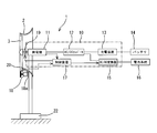
- Example 1 of the present invention The partially broken perspective view of the fluid machine in Example 1 of the present invention
- the axial sectional view of the casing based on the cycloid curve of the fluid machine in the first embodiment of the present invention (A) Explanatory drawing explaining the flow of the fluid machine of FIG. 1, (b) Explanatory drawing of the size of the casing of FIG.
- Circumferential average and time-averaged pressure distribution around a fluid machine equipped with a casing with a flange height of 10% and a cylinder length of 13.7% (% is the ratio to the throat inner diameter) Circumferential average around a fluid machine provided with a casing based on a cycloid curve in Example 1 of the present invention, time-averaged pressure distribution cloth diagram Circumferential average and time average around the fluid machine provided with the flanged casing of FIG. 4 Circumferential average and time average around a fluid machine provided with a casing based on the cycloid curve in FIG.
- Time average pressure distribution diagram around fluid machine in Example 3 of the present invention Circumferential average and time average streamline diagram around casing with 10% height and 22% length of cylinder in Fig. 16
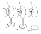
- FIG. 16 (a) The distribution diagram which shows distribution of the circumferential direction average and time average vorticity in the flow field around the thickness cutting edge casing of the fluid machine in Example 3 of this invention Distribution diagram of radial velocity component averaged in the circumferential direction and time averaged around a fluid machine having a casing with 10% and a cylinder length of 22% in FIG. 16 (a) Distribution diagram of radial direction velocity component averaged in circumferential direction and time average around fluid machine in Example 3 of the present invention Wind turbine generator internal block configuration diagram in Embodiment 4 of the present invention Explanatory drawing of the wind power generator which attached the mesh in Example 5 of this invention External view of the tidal current power generator in Example 6 of the present invention
- a casing having an annular shape and an axial cross section having a non-streamline shape, and an impeller disposed around a throat portion in the casing and rotating around the axis.
- the flow flowing through is divided into inner and outer flows at the leading edge and forced flow separation occurs. This separation forms a vortex behind the casing, and the vortex row and vortex row fluctuations have a cell structure in the annular direction.
- a fluid machine that uses an unsteady flow that forms a pressure region and increases the flow velocity of the internal flow that flows in the casing, and a reference line that is a reference for forming the casing thickness is a leading edge in the axial section.
- a vortex generating portion for generating a negative pressure region is formed on the throat side adjacent surface adjacent to the vortex generating portion, and a second outflow gradient is formed at the boundary position to separate the internal flow, and the casing
- a first outflow gradient that separates the external flow at the rear edge position is formed at the rear edge on the outer peripheral surface of the first outer surface, and the first outflow gradient is equal to or greater than the gradient of the conical bus line connecting the front edge and the rear edge.
- the second outflow gradient is set to a gradient lower than the gradient of the tip of the vortex generator when the reference cycloid curve is the inner circumferential surface, and is a non-aerodynamic casing
- This is a fluid machine using an unsteady flow characterized by generating a negative pressure region with a strong vorticity behind the vortex generator to increase the internal flow.
- This configuration makes it easy to design and manufacture the casing, and forms a strong and stable vortex flow in the flow according to the shape of the casing, realizing a strong negative pressure area near the casing on the outlet side.
- the flow can be increased, the length of the diffuser is short, the size can be increased, and the output can be increased.
- a third aspect of the present invention is a form subordinate to the first aspect of the present invention, wherein the casing is made of a plate material having a wall thickness of a predetermined width, and the reference line is the leading edge and the tip of the vortex generator.
- a cycloid curve having a convex portion at the position of the throat portion, and a straight line or a second curve for forming a vortex generating portion between the leading edge of the vortex generating portion and the trailing edge, and a leading edge and a trailing edge Is a fluid machine using an unsteady flow, characterized in that the slope of the conical bus line connecting the leading edge and the trailing edge is set to a positive slope smaller than 40 °.
- the form of the fourth invention of the present invention is a form subordinate to the form of the first invention, wherein the non-streamline shape is formed into a shape in which the wall thickness gradually increases or decreases gradually in the axial section, It is a fluid machine using unsteady flow characterized in that a part or all of the shape on the inner peripheral side is composed of a reference cycloid curve.
- a fifth aspect of the present invention is a form dependent on the second aspect of the present invention, and only the rear edge of the front edge and the rear edge has a thickness of a predetermined width in the radial direction in the axial cross section.
- the fluid machine utilizes an unsteady flow, wherein the vortex generator is a ring-shaped plane having a predetermined width.
- This configuration realizes a favorable negative pressure region behind the vortex generator and a strong negative pressure region behind the vortex generator because the vortex generator is a ring-shaped plane and a suitable negative vortex generation characteristic by the cycloid. Can be increased.
- a sixth aspect of the present invention is a form dependent on the first aspect of the present invention, and is characterized in that a plurality of phase control plates for aligning the phases of flow vortex line fluctuations are provided in the vortex generator. It is a fluid machine using unsteady flow. With this configuration, the flow cell structure can be clarified by aligning the phase in which the vortex formation fluctuates in the circumferential direction as well as suitable vortex generation characteristics by the cycloid, and a strong negative pressure negative pressure region is provided near the casing on the outlet side. Realize and increase the internal flow.
- a seventh aspect of the present invention is a form subordinate to any one of the first to sixth aspects of the invention, and the impeller includes a power generation device that converts the rotational force of the impeller into electric force. Is a fluid machine using an unsteady flow characterized by being connected to each other. With this configuration, high power generation can be performed depending on the shape of the casing.
- An eighth aspect of the present invention is a form subordinate to any one of the first to seventh aspects of the present invention, wherein an unsteady flow characterized in that a conductive mesh is attached to the casing. It is a fluid machine used. With this configuration, the flow is stabilized by the shape of the casing, and the electromagnetic wave shielding effect of the fluid machine from the Doppler radar can be expected.
- a casing having an annular shape whose axial cross section is a non-streamline shape, and an impeller disposed around a throat portion in the casing and rotating around the axis.
- the flow flowing through is divided into inner and outer flows at the leading edge and forced flow separation occurs. This separation forms a vortex behind the casing, and the vortex row and vortex row fluctuations have a cell structure in the annular direction.
- a wind turbine that forms a pressure region to increase the flow velocity of the internal flow through the casing, and a reference line that is a reference for forming the casing thickness is between the leading edge and the trailing edge in the axial section.
- a cycloid curve having a convex portion at the position of the throat portion between the front and rear edges, and a negative pressure region on the inner peripheral side surface in the radial direction of the casing on the downstream side of the throat portion and the throat portion.
- a vortex generating portion is formed, and a throat side adjacent surface adjacent to the vortex generating portion is formed with a second outflow gradient that separates the internal flow at the boundary position, and on the outer peripheral surface of the casing
- a first outflow gradient is formed at the trailing edge to separate the external flow at the trailing edge position, and the first outflow gradient is set to a gradient equal to or greater than the gradient of the conical bus line connecting the leading edge and the trailing edge.
- the outflow gradient of 2 is set to a gradient below this with respect to the gradient of the tip of the vortex generator when the reference cycloid curve is the inner surface, and is strong behind the vortex generator by a non-streamline casing. It is a windmill characterized by generating a negative pressure region of vorticity and accelerating the internal flow. This configuration makes it easy to design and manufacture the casing, and forms a strong and stable vortex flow in the flow according to the shape of the casing, realizing a strong negative pressure region near the casing on the outlet side, and reducing the internal flow.
- the speed can be increased, the length of the diffuser is short, the size can be increased, and the output can be increased.
- the tenth aspect of the present invention is a form subordinate to the ninth aspect of the present invention, and the vortex is generated when the leading edge and the trailing edge have a predetermined thickness in the radial direction in the axial section.
- It is a windmill characterized by comprising the shape of the inner peripheral side of the casing containing a part by the reference
- An eleventh aspect of the present invention is a form subordinate to the ninth aspect, wherein the casing is made of a plate material having a wall thickness of a predetermined width, and the reference line is the leading edge and the tip of the vortex generator.
- a cycloid curve having a convex portion at the position of the throat portion, and a straight line or a second curve for forming a vortex generating portion between the leading edge of the vortex generating portion and the trailing edge, and a leading edge and a trailing edge Is a windmill characterized in that the slope of the conical bus line connecting the leading edge and the trailing edge is set to a positive slope smaller than 40 °.
- a twelfth aspect of the present invention is a form subordinate to the ninth aspect, wherein the non-streamline shape is formed into a shape in which the wall thickness gradually increases or decreases gradually in the axial section,
- the wind turbine is characterized in that a part or all of the shape on the inner peripheral side is constituted by a reference cycloid curve.
- a thirteenth aspect of the present invention is a form dependent on the tenth aspect of the present invention, and only the rear edge of the front edge and the rear edge has a thickness of a predetermined width in the radial direction in the axial section.
- the vortex generator is a ring-shaped plane having a predetermined width. This configuration realizes a favorable negative pressure region behind the vortex generator and a strong negative pressure region behind the vortex generator because the vortex generator is a ring-shaped plane and a suitable negative vortex generation characteristic by the cycloid. Can be increased.
- a fourteenth aspect of the present invention is a form subordinate to the ninth aspect of the present invention, and is characterized in that a plurality of phase control plates for aligning the phases of flow vortex street fluctuations are provided in the vortex generator. It is a windmill. With this configuration, the flow cell structure can be clarified by aligning the phase in which the vortex formation fluctuates in the circumferential direction as well as suitable vortex generation characteristics by the cycloid, and a strong negative pressure negative pressure region is provided near the casing on the outlet side. Realize and increase the internal flow.
- a fifteenth aspect of the present invention is a form subordinate to any of the ninth to fourteenth aspects, wherein the impeller includes a power generator that converts the rotational force of the impeller into electric force. Are connected to each other. With this configuration, high power generation can be performed depending on the shape of the casing.
- a sixteenth aspect of the present invention is a wind turbine according to any one of the ninth to fifteenth aspects, wherein a conductive mesh is attached to a casing. With this configuration, the flow is stabilized by the shape of the casing, and an electromagnetic wave shielding effect of the windmill from the Doppler radar can be expected.
- an impeller is provided in a casing having an annular shape and an axial cross section of a non-streamline shape, and the flow flowing around is divided into internal and external flows at the leading edge and forced.
- the internal flow that flows in the casing by forming a vortex behind the casing by this separation and forming a negative pressure region having a cell structure in the annular direction by the vortex and the fluctuation of the vortex.
- An internal flow acceleration method using an unsteady flow that increases the flow rate and connects a reference line, which is a reference for thickness formation of the casing, between the leading edge and the trailing edge in the axial section and before and after this
- a cycloid curve having a convex portion at the position of the throat portion between the edges, and a vortex generation for generating a negative pressure region on the inner peripheral side surface in the radial direction of the casing on the throat portion and the downstream side of the throat portion Forming part and further
- a second outflow gradient that separates the internal flow is formed at the boundary position on the throat side adjacent surface adjacent to the vortex generating portion of the casing, and the external flow at the rear edge is formed at the position on the outer peripheral side surface of the casing.
- the gradient of the tip of the vortex generator when the cycloid curve is the inner surface is set to a gradient below this, and a negative pressure region with strong vorticity is generated behind the vortex generator by a non-streamline casing
- the internal flow speed increasing method using the unsteady flow is characterized by increasing the internal flow speed.
- This configuration makes it easy to design and manufacture the casing, forms a strong and stable vortex flow in the flow according to the shape of the casing, and realizes a negative negative pressure region near the casing on the outlet side, The internal flow can be accelerated by the external flow.
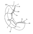
- FIG. 1 is a partially broken perspective view of a fluid machine in Embodiment 1 of the present invention
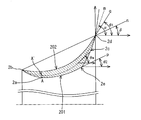
- FIG. 2 is based on a cycloid curve provided between a leading edge and a trailing edge of the fluid machine in Embodiment 1 of the present invention.
- An axial sectional view of a thick casing is shown
- FIG. 3 is an explanatory view for explaining the flow of the fluid machine of FIG.
- the fluid machine in the first embodiment of the present invention is a windmill 1, and a generator for power generation is connected (see FIG. 30).
- a generator for power generation is connected (see FIG. 30).
- the windmill 1 has an impeller 3 that is rotated around an axis by the wind and an annular shape in which each axial cross-section is non-streamlined, and the overall shape is also non-streamlined and surrounds the impeller 3. Is provided with a diffuser type casing 2.
- the impeller 3 is disposed in the casing 2 through a small gap between the rotating surface at the tip of the wind turbine 1 and the casing 2, and the wind turbine 1 has an annular shape in the axial direction of the wind turbine 1.
- the casing 2 of the first embodiment is a diffuser type (expanded shape), and the reason for the diffuser type is that the flow velocity at the tip of the impeller 3 is maximized at the throat portion 2a (the portion of the minimum cross-sectional area of the casing 2), and the nozzle This is because the structure is more compact than the type (reduced shape). From the leading edge 2b to the throat portion 2a, an inflow portion is formed, and the flow passage cross-sectional area is gradually reduced and accelerated. The flow path cross-sectional area is enlarged from the throat portion 2a to the rear edge 2d, and is decelerated.
- this throat part 2a is arrange
- the casing 2 in the first embodiment has a non-streamline shape, and the flow flowing through the casing 2 is divided into the inner and outer flows by the casing 2 to forcibly separate the flow, thereby forming a vortex street on the rear side. Then, a strong negative pressure negative pressure region having a cell structure in the annular direction is formed behind the casing 2 by the vortex row and the vortex row fluctuation, and the flow velocity of the internal flow flowing in the casing 2 by the action of the negative pressure region. Is to increase. Then, in order to increase the strength of the vortex of the vortex row to further reduce the negative pressure region, an attempt is made to optimize the shape of the casing 2.
- vortex generation for separating the internal flow from the surface on the inner peripheral surface 201 of the casing 2 on the downstream side of the throat portion 2 a is performed.
- a surface 2c (a vortex generator in the first embodiment of the present invention) is provided.
- the internal flow that flows in from the opening of the inlet of the casing 2 develops a boundary layer from the vicinity of the throat portion 2 a and is separated at the tip 2 e of the vortex generating portion on the inner peripheral surface 201.
- the internal flow that flows inside is accelerated.
- the negative pressure region S of the cell structure formed by the vortex row and the vortex row fluctuation will be described.
- the vortex street is generated non-stationarily (alternately) on the downstream side of the casing 2 as shown in FIG. That is, assuming a casing shape as shown in FIG. 3B, the radial height h of the vortex generating surface 2c is sufficiently smaller than the inner diameter d of the throat portion 2a of the casing 2 (h / d ⁇ 1). ),
- a plurality of cells in the negative pressure region S having a size of a vortex fluctuation scale are formed in an annular shape behind the vortex generating surface 2c by a vortex formed at a certain timing. As the vorticity in this region increases, the negative pressure further decreases.
- the cylinder length (casing axial direction length) at this time is Lt.
- the flow inside and outside the casing 2 is peeled off at the peeling points on the outer peripheral surface and the inner peripheral surface of the casing 2, and Karman vortices are formed at each downstream cross section in the circumferential direction. And in the cross section and the vortex formation in the cross section, there are strong vortex formation, weak vortex formation and fluctuation (unevenness) in the circumferential direction.
- the circumferential range in which the strong vortex formation and the weak vortex formation appear is slightly smaller than the axial vortex row fluctuation scale (3d c to 4d c , where d c is the diameter of the cylinder) of the two-dimensional cylinder.
- the vortex row fluctuation scale in the circumferential direction is 2D to 3D. This corresponds to the fact that the two-dimensional cylinder is closed in an annular shape to form a three-dimensional shape, and is supported quantitatively.
- a negative pressure region cell in which strong vortex formation has occurred becomes a negative pressure region S having strong vorticity. Due to fluctuations in the flow, any of the cells becomes stronger or weaker independently. These cells alternate with each other.
- the negative pressure region S with strong vorticity the pressure around the vicinity is reduced, and the flow velocity of the internal flow is improved by the pressure difference.
- the impeller 3 rotates at a high speed, and the wind turbine 1 can output a driving force with a high torque, and a high-output power can be generated.
- the condition (h / d ⁇ 1) that the height h in the radial direction of the vortex generating surface 2c is sufficiently smaller than the inner diameter d of the throat portion 2a of the casing 2 is often satisfied.
- the flow including the negative pressure region S having such a strong vorticity cannot be easily created. This is because simply making the casing 2 non-streamline causes pressure loss, the strength of the vortex street vortex does not increase, and the negative negative pressure region S does not appear clearly. It is.
- the ideal casing must have a shape that can create a strong vortex flow and a negative pressure region S with a strong negative pressure without causing unnecessary loss in the flow as much as possible.
- the windmill 1 does not have the impeller 3 serving as a resistor, it can be analyzed by a potential flow assuming that there is no separation in the flow.
- the flow flowing along the inner peripheral surface 201 of the casing 2 is near the throat portion 2a. Shows the maximum flow rate.
- the casing of the present invention is a structure that, when the impeller 3 is present, does not cause unnecessary pressure loss and causes effective separation only for the formation of the vortex street, and as a result, the throat portion It is a shape that forms a low-pressure negative pressure region S that increases the internal flow in the vicinity.
- the inventors of the present invention have conventionally tried various shapes such as making the vortex generating surface 2c a ridge. However, I felt that these shapes had room for improvement. Then, through trial and error, a comparative study was conducted, and the knowledge that the cycloid known as the shortest descending line has a shape that sufficiently satisfies the ideal casing conditions was obtained.
- a casing based on a cycloid curve hereinafter also referred to as a cycloid-shaped casing or a cycloid casing
- vortex formation characteristics of a casing having an inner peripheral surface formed of the cycloid itself will be described later. Examples 2 and 3 will be described in detail.
- the casing based on the cycloid curve is the casing of the rotating body with the curve as the generating line when the casing thickness can be ignored. It means a casing of a rotating body to which a wall thickness is given with respect to a bus bar when possible.
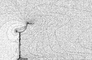
- FIG. 5 shows the pressure distribution obtained by averaging the time average in the circumferential direction around the windmill 1 provided with the cycloid casing.
- the numerical calculation uses a large compact simulation method (LARGE-EDDY-SIMULATION__, commonly known as the LES method), which is the most advanced turbulent model using the RIAM-COMPACT numerical simulator developed at the Institute of Applied Mechanics of Kyushu University. ) Using high Reynolds number analysis software and direct numerical calculation without using any turbulence model (DIRECT NUMERICAL SIMULATION, commonly known as _DNS method). The calculation results in the figure shown here are based on the DNS method. The LES method was used for reference. Details of the shapes of the flanged casing and the cycloid casing are as shown in FIG. FIG. 8 is a diagram comparing the shapes of a casing with a hook height of 10% and a tube length of 13.7% for a numerical calculation and a cycloid casing.
- the shape is consistent up to the vicinity of 09.
- the cycloid shape is extended from this position to the same height as the height h of the ridge.
- d is the diameter of the throat portion
- h is the height h in the radial direction of the vortex generating surface 2c.
- Lt 0.137d
- h 0.137d
- the flanged casing has a shape in which a flange is provided at the rear end to increase the outer diameter of the diffuser outlet, but the cycloid casing extends the cycloid shape to the flange outer diameter of the flanged casing, By itself, it is intended to be integrated with the kite.
- FIG. 4 it can be seen that a high pressure region is formed on the front side of the kite and a negative pressure region that is not so low pressure is formed on the downstream side of the tip of the kite.
- the pressure distribution of the cycloid-shaped casing 2 has no unnecessary high-pressure portion, and is extremely smooth and unique, and bites into the throat portion side from the vicinity of the rear edge of the back surface of the casing 2.
- a negative pressure region is formed.
- the casing is composed of a cycloid curve, the flow is constricted at the throat part and expanded on the downstream side, but the fluid particles in the meantime are along the plane formed by the shortest descending line, so to speak, the minimum time.
- the casing with a rod height of 10% and the cylinder length of 13.7% has a large pressure loss and the action of the negative pressure region is small, but in the case of a cycloid casing, the fluid resistance is small and the negative pressure region is strong. It can be seen that the pressure is negative and the effect on the internal flow is strong.
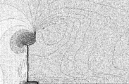
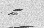
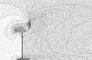
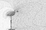
- FIG. 6 is an explanatory diagram of a streamline averaged and time-averaged around the windmill 1 having the flanged casing of FIG. 4
- FIG. 7 is an average of the circumferential direction around the windmill 1 having the cycloid casing of FIG. It is explanatory drawing of the streamline which carried out the time average. According to this, even if it is a non-streamline shape, it can be understood that the flow around the flanged casing is a flow having an unstable region that swells backward due to the main flow being disturbed by the presence of the casing. The flow is blocked here by a trap.
- the flow of the cycloid casing forms a strong negative pressure region vortex behind the casing without the main flow being disturbed by the casing. Moreover, in the cycloid shape, it can be seen that the flow jumps out smoothly on the upper surface at the rear edge of the casing 2. This is because there is no damming by a casing like a bag.
- the vortex generating surface 2c of the casing 2 does not have an excessively sharp shape, becomes an appropriate non-linear shape that does not disturb the flow more than necessary, and has a jump angle from the trailing edge of the flow. More inward facing.
- the internal and external flows smoothly merge on the time average in the range of about 1 to 2 times the axial length of the casing behind the vortex generating surface 2c.
- a strong negative pressure region vortex is formed in the immediate vicinity of the vortex generating surface 2c, and this action increases the flow velocity of the throat portion 2a and increases the wind turbine output.
- FIG. 9 shows a numerical calculation of the distribution of the average and time average vorticity in the circumferential direction in the flow field around the casing with a kite height of 10% and a cylinder length of 13.7%.
- the portion with a strong vorticity is formed as a thin and long region on the wake side near the tip of the impeller.
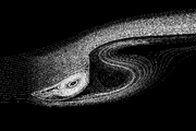
- FIG. 10 shows a numerical calculation of the distribution of the circumferential average / time average vorticity in the flow field around the cycloid casing.
- a region of extremely strong vorticity is formed near the rear of the vortex generating surface and in the vicinity of the wind turbine outlet. Strong vorticity increases the negative pressure and increases the flow velocity of the surrounding flow.
- the cycloid casing When compared with other shaped casings, the cycloid casing is very clearly superior in terms of lowering pressure, clarifying, stabilizing and smoothing the negative pressure region, as can be seen in FIGS.
- Have The vortex street flow formed on the wake side in the negative pressure region having a strong vorticity in the range of 1 to 2 times the axial length of the casing is a unique characteristic that cannot be formed by other shapes of the casing.
- the casing shape may be configured based on the cycloid curve. That is, when the wall thickness can be ignored, the cycloid casing having the above-mentioned cycloid curve as a generating line can be used as it is (see Example 2 for details), and in the case of a casing that is thin but cannot be ignored.
- the shape that becomes the skeleton of the casing is determined based on the above-described reference cycloid curve, and the shape close to the cycloid casing is filled.
- the reference cycloid curve must be a cycloid curve having a convex portion that communicates between the front edge 2b and the rear edge 2d in the axial section and is formed corresponding to the throat portion 2a between the front and rear edges. I must. This is because the cycloid curve is shaped at both ends and the position of the maximum value or the minimum value between them. Even when the cycloid casing is fleshed, if the cycloid casing is used as a reference, vortex formation characteristics equivalent to the vortex formation characteristics due to the cycloid shape are exhibited.
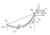
- FIG. 2 is an axial cross section of a casing having a thickness based on a cycloid curve provided between the leading edge and the trailing edge.
- the casing 2 is a crescent shape in which the thickness of the axial cross section gradually increases and decreases, and is a rotating body that expands with a certain gradient from the front edge 2b to the rear edge 2d.
- the gradient n of the conical bus line connecting the front edge 2b and the rear edge 2d in FIG. 2 is the spread angle ⁇ . That is, it is a conical and annular rotating body.
- a reference line serving as a reference for determining the skeleton of the casing 2 is a cycloid curve m connecting the front edge 2b and the rear edge 2d. Since the throat portion 2a is formed in the wind turbine 1 of the first embodiment, the cycloid curve m has a convex portion A ′ as shown in FIG. 2 (the minimum value in the cross section of FIG. 2). The position of the convex portion A ′ is the same as the position of the convex portion A having the minimum cross-sectional area of the inner peripheral surface 201 in the axial direction. Note that the convex portion A and the convex portion A ′ have both the minimum value and the maximum value depending on the direction of the cross section of the rotating body.
- the shape of the inner peripheral surface 201 of the casing 2 is fleshed so as to gradually increase and decrease along the cycloid curve m.
- the radius gradually increases from the leading edge 2b to the throat portion 2a. Is reduced, and the radius is increased from the throat portion 2a to reach the trailing edge 2d.
- a range of a predetermined length from the rear edge 2d of the inner peripheral surface 201 is a line that serves as a generating line that forms the vortex generating surface 2c.
- a cycloid shape with negligible wall thickness is most suitable, and the inner peripheral surface 201 is preferably a thin-walled shape as close to the cycloid curve m as possible.
- the end point on the inner diameter side of the vortex generating surface 2c is the vortex generating portion tip 2e.
- an outflow gradient that separates the internal flow is formed at the boundary position on the front edge side (the position of the inner peripheral surface 201 is the tip 2e of the vortex generating portion).
- a boundary layer develops from the vicinity of the throat portion 2a to the outside of the internal flow, and the flow is separated at the vortex generating portion tip 2e due to the presence of the vortex generating surface 2c.
- the inner peripheral surface 201 has a shape in which the gradient changes discontinuously at the normal vortex generator tip 2e.
- the inner peripheral surface 201 has a cycloid shape having a cycloid curve as a generatrix, only a part of the wake side of the shape becomes the vortex generating surface 2c as it is to become the vortex generating surface 2c (that is, after the separation point of the cycloid curve). Part of the vortex generation surface 2c as it is before the separation point, and the vortex generation part tip 2e is separated.
- the peeled internal flow, together with the peeled external flow, is wound behind the casing 2 as shown in FIG. 3A to form a vortex street in the wake, and a negative pressure with a strong vorticity just behind the vortex generating surface 2c. Form a region.
- an outflow gradient ⁇ ⁇ b> 2 for separating the internal flow is provided on the inner peripheral surface (adjacent surface in the first embodiment of the present invention) immediately upstream of the vortex generator tip 2 e. That is, an inclined surface in the tangential p direction is formed on the immediate upstream side of the vortex generator tip 2e to promote flow separation.
- the outflow gradient ⁇ 2 may be set to a gradient less than or equal to the gradient of the vortex generating portion tip 2e where separation occurs when the inner peripheral surface 201 is the cycloid curve m.
- the case of the cycloid curve m is the reference, and when fleshing, the gradient is less than this reference value ⁇ m.
- the outflow gradient ⁇ 2 at U is set. Since the radius of curvature is larger than the cycloid curve m on the inner peripheral side, and the separation point (vortex generator tip 2e) moves to the trailing edge side with this, the outflow gradient ⁇ 2 becomes a gradient less than the reference value ⁇ m. ( ⁇ 2 ⁇ m).
- the exact relationship between the inner peripheral surface, the position of the vortex generating portion tip 2e, and the gradient ⁇ 2 is preferably obtained based on experiments.
- the wall surface of the flow in the boundary layer of the inner peripheral surface The point where the shear stress becomes 0 is determined and used as the peeling point. For example, assuming a coordinate system with x along the wall surface direction and y in the normal direction in the flow, if the flow velocity of the flow is u, the shear stress is ⁇ du / dy ( ⁇ is the viscosity coefficient of the fluid.
- the outflow gradient ⁇ 2 is decreased, the vortex generating portion tip 2e approaches the throat portion side, and when increased, the vortex generating portion front end 2e approaches the trailing edge side.
- the position of the separation point (vortex generator tip 2e) is affected by the wind speed U.
- a slight difference in the outflow gradient ⁇ 2 is absorbed in the change in the wind speed of the natural wind.
- Any outflow gradient ⁇ 2 may be used as long as the flow can be separated at the tip 2e of the vortex generator 2 when the output of the wind turbine 1 such as power generation is performed. If the gradient of the cycloid shape is set to be equal to or less than the reference gradient, the flow is separated at or near the planned vortex generating portion tip 2e, and a strong vortex row can be generated.
- the outflow gradient ⁇ 2 is set to a predetermined gradient ( ⁇ 2 ⁇ ⁇ 90 °) less than ⁇ determined from the cycloid based on the gradient ⁇ of the trailing edge 2d of the cycloid curve m (for example, a linear function of ⁇ or ⁇ It is possible to set the gradient so that the internal flow is peeled off from the inner peripheral surface 201 by simply associating with ⁇ .
- a value close to the gradient ⁇ of the gradually increasing cut end type (banana type cross section) of Example 3 described later may be adopted (see FIG. 7).
- the thin-walled casing as a whole becomes a rotating body having a shape that expands in a trumpet shape.
- a line indicating the inner surface of the thin casing is an inner curve i
- a line indicating the outer surface is an outer curve k.
- the inner wall thickness of the throat portion of the cycloid curve m and the inner curve i is denoted by ⁇ i .
- d m is the diameter of the throat portion of the cycloid m.
- the thin inner curve i in the axial section satisfies the following conditions (1) and (2). That is, (1) the inner curve i intersects with the cycloid curve m at the leading edge 2b. (2) The inner curve i also has a minimum value or a maximum value at the throat portion at the same position in the axial direction of the throat portion of the cycloid curve m. Further, (3) the inner curve i can be easily designed by adding a condition that intersects the cycloid curve m at the trailing edge 2d. Then, the inner curve i is connected to the trailing edge 2d from the tip 2e of the vortex generating portion on the line by a straight line or a curve with a small curvature to form a vortex generating surface 2c.
- the inner curve i has a maximum value or a minimum value between the leading edge 2b and the trailing edge 2d, such as a quadratic function, a higher-order third-order or higher power function, or a trigonometric function, and the condition (1) (2) Furthermore, it can be expressed by using a convex function or a concave function that satisfies (3).
- the overall thickness ⁇ is formed by the inner thickness ⁇ i and the outer thickness ⁇ k .
- the inner wall thickness delta i of the throat portion is a thickness that the inner wall thickness of the thin casing is maximized.
- the convex function or the concave function may be a function that increases or decreases monotonously and smoothly up to the throat portion, and that decreases or increases monotonously and smoothly from the throat portion.
- the skeleton of the shape is the same cycloid curve m and is common.
- the flow paths are almost the same, and the flow is almost the same except for a very microscopic flow.
- L is a representative dimension
- U is a representative flow velocity
- ⁇ is a kinematic viscosity coefficient.
- Flow passage area A of the internal flow path configured as a rotary member cycloid m is [pi] d m 2/4 at the throat portion, the flow passage area A i that is configured as a rotary member of the inner curve i [pi] d in the throat 2 / 4 ⁇ (d m 2 ⁇ 4 ⁇ i d m ) / 4.
- Re ′ d i U i / ⁇ Ud (1 + 2 ⁇ i / d) / ⁇ in the flow of the rotating body of the inner curve i. It becomes.
- the thickness ⁇ k is, for example, the same thickness as ⁇ i
- the thickness ⁇ of the thin casing is 2 ⁇ i .
- ⁇ / Lt 0.1. Since ⁇ i is closer to the cycloid casing with a thinner thickness, the total thickness ⁇ of the thin-walled casing is about 10% of Lt, or a thin-walled casing whose thickness does not change the flow pattern. Can do.
- ⁇ i may be 0, and at this time, the inner curve i is constituted by the cycloid curve m itself. In the case of a negligible thickness, the inner curve i ⁇ the cycloid curve m ⁇ the outer curve k can be paraphrased.
- the shape of the outer peripheral surface 202 of the casing 2 will be described.
- the shape of the outer peripheral surface 202 is also thickened along the cycloid curve m so as to be curved in a concave shape from the front edge 2b to the rear edge 2d.
- the outer peripheral surface 202 is appropriately curved, and if the separation occurs at the trailing edge 2d, a desired vortex street flow can be formed.
- Various cross-sectional shapes can be employed.
- the thickness of the casing 2 causes the weight to increase. Moreover, even if the pressure loss due to the wind is too large, the practicality is lost.
- an outflow gradient ⁇ 1 for separating the external flow at the position of the rear edge 2d is formed on the rear edge 2d.
- ⁇ 1 is the angle of intersection of the outer curve k with the tangent q direction and the axial direction (see FIGS. 2 and 3B).
- the outflow gradient ⁇ 1 is set to be equal to or larger than the spread angle ⁇ , which is an intersection angle between the generatrix n connecting the front edge 2b and the rear edge 2d and the axial direction. Set (that is, ⁇ ⁇ 1).
- the spread angle ⁇ exceeds 50 ° is a relatively short tube length.
- the rod height h is 15%. This corresponds to such a case (that is, a casing with a hook with a hook height of 15% and a cylinder length of 13.7%), and the expansion angle ⁇ at this time is approximately 51 °. It is preferable that ⁇ ⁇ 40 ° (this will be described later). However, in the case of an exceptional fluid machine that does not require practicality, an expansion angle exceeding 50 ° may be useful.
- the outflow gradient ⁇ 1 must be an angle that stabilizes the flow separation at the trailing edge 2d and causes it to occur in a fixed manner. Therefore, the shape of the outer peripheral surface 202 of the casing 2 is such that the external flow is separated at the rear edge 2d, and the inner flow separated at the inner peripheral surface 201 is entangled behind the casing 2 and the vortex row is strong against the wake. It is necessary for the shape to form. That is, by using the cycloid and the gradients ⁇ 1 and ⁇ 2, the internal flow flowing on the inner peripheral side of the cycloid shape is linked with the external flow to form a strong vortex row in cooperation, and the internal flow is accelerated by this action.
- the shape in which the outer peripheral surface 202 bulges outward in the radial direction is not preferable because the peeling point may move upstream from the trailing edge 2d, resulting in excessive weight and unnecessary pressure loss.
- the outflow gradient ⁇ 1 is set to be equal to or larger than the expansion angle ⁇ , there is no such possibility.
- both ends (The front edge 2b, the rear edge 2d) and the cycloid curve of the bus bar with the fixed throat portion are unambiguous, and this cycloid curve can be called a curve inherent to the casing cross-sectional shape, and this casing is based on this cycloid curve. It can be said that it is set as a line.
- the thin wall is a wall thickness that satisfies the conditions of the outflow gradients ⁇ 1 and ⁇ 2, and as described above, a wall thickness that is generally within 10% of Lt is preferable.
- the gradient of the tangent line of the outer peripheral surface 202 at the position where this rounding is started becomes the outflow gradient ⁇ 1 of the trailing edge 2d.
- the shape may satisfy the condition of the outflow gradient ⁇ 1 at the outer peripheral edge of the end surface.
- the flow is the same as when there is no thickness.
- the leading edge is preferably formed into a pointed shape that can smoothly divide the flow or a rounded rounded shape, but if the overall vortex flow becomes stronger, for example, a cutting edge having a flat end face You may make it into a shape.
- the shape serving as the reference of the casing the shape of the inner peripheral surface and the outer peripheral surface is determined based on the cycloid curve in the axial cross section.
- a strong vortex array is formed, and this vortex array can generate a negative pressure region with a strong vorticity behind the vortex generation surface to accelerate the internal flow.
- a lightweight and compact fluid machine and windmill can be provided.
- the length of the diffuser is short, the size can be increased, and high output can be achieved.
- a stable strong vortex vortex street flow is formed in the flow according to the shape of the casing, and a strong negative pressure negative pressure region is formed near the outlet side.
- the internal flow can be accelerated by the vortex street flow which is an unsteady flow.
- the second embodiment of the present invention is a case where the casing of the fluid machine and the windmill described above is formed of a plate material having a predetermined thickness in the radial direction, and includes a shape on the inner peripheral side including the vortex generating surface. It itself is composed of a cycloid curve. Therefore, there is no difference between the first embodiment and the basic.
- FIG. 11 is a sectional view in the axial direction of a casing of a plate material formed of a cycloid curve provided between a front edge and a rear edge of a fluid machine in Embodiment 2 of the present invention.
- the description will focus on the wind turbine, but the same applies to other fluid machines such as a water turbine.
- the inner peripheral surface 201 is formed into a cycloid shape using a plate material.
- a plate material having a predetermined thickness ⁇ is considered from the scale of the representative dimensions of a fluid machine, the thickness ⁇ can usually be handled as a negligible thickness. That is, normally, the ratio of the plate thickness to the throat radius is 0.5% or less, and the casing may be formed assuming that ⁇ 0.
- the plate material having a predetermined thickness ⁇ is a case where the ratio of the plate thickness to the radius of the throat portion exceeds 0.5%, for example.
- an inner peripheral surface 201 is a cycloid curve m that connects a front edge inner end 2 b 1 and a rear edge inner end 2 d 1 .
- the throat portion 2a exists at the position S of the minimum cross-sectional area that minimizes the flow path cross section in the inner peripheral surface 201.
- the outer peripheral surface 202 is also a cycloid curve parallel to the inner peripheral surface 201 separated by the thickness ⁇ .
- the slope of the conical bus line connecting the front edge outer end 2b 2 and the rear edge outer end 2d 2 is set to the spread angle ⁇ .
- a range of a predetermined length from the rear edge 2d of the inner peripheral surface 201 is the vortex generating surface 2c.
- the end on the inner diameter side of the vortex generating surface 2c is the vortex generating portion tip 2e.
- the boundary layer develops from the vicinity of the throat portion 2a to the vortex generating portion tip 2e.
- the inner peripheral surface 201 can be partly covered with the vortex generating surface 2c as it is, and the flow is separated at the vortex generating portion tip 2e to form a very effective strong vortex street. it can.
- the vortex generating surface 2c need not have a shape different from that of the cycloid.
- the vortex generator tip 2e can be made the separation point simply by adopting the cycloid shape.
- ⁇ 2 ⁇ m as in the first embodiment.
- the peeled internal flow together with the external flow peeled off at the rear edge outer end 2d 2 of the outer peripheral surface 202, is engulfed at the rear of the casing 2 to form a Karman vortex-like vortex array in the wake and immediately on the vortex generating surface 2c.
- a negative pressure region with a strong vorticity is formed in the annular direction accompanying the rear.
- the cycloid casing includes an outflow gradient ⁇ 2 that faces the tangential p direction at the vortex generating portion tip 2e of the cycloid curve m.
- the shape of the outer peripheral surface 202 has a shape separated by a thickness ⁇ in the radial direction along the cycloid curve m of the inner peripheral surface 201. Since external flow flowing through the front edge outer end 2b 2 and the rear edge outer end 2d about 2, to form the outflow gradient ⁇ 1 trailing edge outer end 2d 2 As can be seen from the case of delta ⁇ 0. As shown in FIG. 11, the outflow gradient ⁇ 1 is the same as the outflow gradient ⁇ of the cycloid curve m. It is peeled at the position of the trailing edge outer end 2d 2 external flow. Further, it is set to be equal to or smaller than the spread angle ⁇ of the conical bus line connecting the outer edge 2b 2 at the front edge and the outer edge 2d 2 at the rear edge.
- a vortex generating surface 2c is formed vertically in a plate-shaped cycloid-curved casing to have a shape like a brazed casing as shown in FIG. 8, and ⁇ ⁇ 40 as in FIG.
- a shape that attaches a ridge (disk) within a range that satisfies ° may be adopted. What is important is to make the shape in a range satisfying ⁇ ⁇ 40 ° as described in the third embodiment.
- a plate-shaped flanged cycloid casing having a wall thickness ⁇ (including ⁇ 0) is obtained. Also in this case, a stable strong negative pressure region can be formed, and good characteristics are exhibited.
- Example 2 of the present invention before if edge 2b and a trailing edge 2d has a thickness of predetermined width ⁇ radially in axial cross-section (i.e. the leading edge in the end 2b 1 and the rear edge in the end 2d 1, the leading edge In the case of having the outer end 2b 2 and the rear edge outer end 2d 2 ), the shape of the inner peripheral surface 201 is a cycloid shape in which the front edge inner end 2b 1 and the rear edge inner end 2d 1 are connected. Vortex train generation characteristics can be imparted, and strong vortex flow and negative pressure regions can be generated. Moreover, the casing can be easily designed and manufactured.
- a case with a flange and a cycloid casing are compared by a wind tunnel experiment and a numerical calculation, and the fact that the cycloid shape has extremely excellent characteristics will be described following the first embodiment.
- the flanged casing and the cycloid casing that have been subjected to the wind tunnel experiment and the numerical calculation have shapes as shown in FIG.
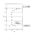
- FIG. 12A shows the result of the wind tunnel experiment
- FIG. 12B shows the result of the numerical calculation.
- 12A shows that the wind turbine output coefficient of the cycloid casing is larger than the wind turbine output coefficient Cw of the flanged casing of FIG.
- the rate of increase is 3.2%. This tendency is the same in the numerical calculation of FIG. 12B, and the rate of increase is 2.9%. Therefore, the wind turbine output coefficient Cw can be expected to increase by about 3% simply by using the cycloid casing.
- W is the power generation output (W)
- ⁇ is the air density (kg / m 3 )
- r 0 is the impeller radius (m)
- the wind speed U (m / s).
- FIG. 13 shows the radial distribution of the flow velocity in the throat portion
- FIG. 14 shows the radial distribution of the pressure in the throat portion.
- FIGS. 4 and 5 and FIGS. 9 and 10 The time average pressure distribution and the circumferential average / time average vorticity distribution around the two wind turbines are as shown in FIGS. 4 and 5 and FIGS. 9 and 10.
- a cycloid casing having a cycloid cross section has a rod height of 10% and a tube length of 13.7% having the same projection width D. It can be seen that a negative pressure region having a negative pressure stronger than that of the casing (see FIG. 3B) is created, and that the negative pressure region extends to the vicinity of the throat portion along the wall surface of the inner peripheral surface of the casing.
- the negative pressure region is a region having a relatively high vorticity and is formed to be thin and long on the wake side near the tip of the impeller.
- a region of extremely strong vorticity is formed from the inner periphery to the outer periphery near the exit and behind the vortex generating surface. Therefore, it can be seen that this strong vorticity negative pressure region of the cycloid casing increases the flow velocity at the throat portion, and accordingly the wind turbine output increases.
- a streamline diagram around a casing with a flange of 10% height and a tube length of 13.7% is as already described with reference to FIG. 6, and a cycloid composed of a plate material having a predetermined thickness in Example 2.
- the streamline diagram around the casing is basically as described in FIG.
- the flow around the flanged casing is largely disturbed by the presence of the casing and spreads backward, and the flow is blocked by the fence.
- the cycloid casing has an appropriate shape that does not disturb the flow more than necessary, and the angle of protrusion from the trailing edge of the flow is more inward. In the cycloid casing, the flow jumps out smoothly on the upper surface at the rear edge of the casing.
- a vortex is formed in the immediate vicinity of the vortex generating surface 2c, and the inner and outer flows smoothly merge in a time-average manner in the wake in the range of about 1 to 2 times the axial length of the casing. This action increases the flow rate of the throat portion 2a and increases the wind turbine output.
- the performance of the wind turbine is improved by using a cycloid casing in which the vortex generating surface and the diffuser are integrated.
- the cycloid casing improves the ability to create a negative pressure region and is extremely excellent in vortex street formation characteristics.
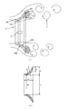
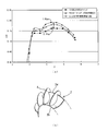
- FIG. 15A shows the output in the case where the wind turbine according to the second embodiment of the present invention is provided with the phase control plate 4 for aligning the vortex line fluctuation, the case where the phase control plate 4 is not provided, and the case with the flanged casing according to the first embodiment.
- FIG. 15B shows the appearance of the casing 2 provided with the phase control plate 4 as shown in FIG.
- the casing 2 in FIGS. 15A and 15B has twelve phase control plates 4 installed.
- twelve sheets are erected in the axial direction at a predetermined pitch on the wake side of the vortex generating surface 2c of the cycloidal casing 2 of the plate material.
- r 0 is the impeller radius
- ⁇ is the angular frequency (1 / s).
- the casing having a cycloid cross section which is composed entirely of a smooth rotating surface of a cycloid curve, also has a trailing edge on the cycloid, and the height h of the portion corresponding to the vortex generating surface 2c is 10 of the diameter d of the throat portion 2a. % Height. That is, the outermost diameter (position of the rear edge) of the casing 2 including the vortex generating surface 2c is equal to each other (see FIG. 4).
- the wind speed is 8 (m / sec), and the diameter of the impeller 3 is 1000 mm.
- an average increase in the output coefficient Cw of 2.5% is expected by making the cycloid curve.
- the height is increased by about 1.5%.
- the effect of the phase control board 4 includes Example 1 and Example 3 mentioned later, and others. The same applies to fluid machines.
- the number of phase control plates is larger than the number of cells in the negative pressure region formed by the natural flow, the original cells will be forcibly divided, and the vortex on the wake side will be too much. It does not become a strong vortex.
- the negative pressure region is also unnoticeable. Even when the number of phase control plates is smaller than the number of cells, a plurality of cells expand and contract with each other and influence each other to weaken the stabilizing action, and in this case, the vortex is not stronger than in the case of the same number. . Therefore, it is preferable to provide the number of phase control plates as many as the number of the negative pressure regions that are naturally formed. Twelve phase control plates 4 are also selected from this viewpoint.
- the fluid machine according to the second embodiment makes it easy to design and manufacture the casing by using the rotating surface of the cycloid curve, and can stabilize the flow forming the vortex street. It is possible to increase the flow velocity of the internal flow and generate high output power.
- the length of the diffuser can be shortened, which makes it possible to increase not only micro windmills and mini windmills of several meters or less, but also windmills for large wind power generators with a power generation capacity of MW class, and energy conversion rate Can be high.
- the flow forming the vortex street can be made more stable by making the whole into a cycloid curve, The flow velocity can be increased.
- Embodiment 3 of the present invention is to change the wall thickness of the casing of the fluid machine and form a bowl-shaped vortex generating surface.
- it has a shape of a cross section at the thickness cutting edge that gradually increases and decreases the thickness.
- FIGS. 16 (a) and 16 (b) are comparative views comparing the shape of a casing with a hook height of 10% and a cylinder length of 22% and the casing of the thickness cut end section of Example 3, and FIG. It is an axial sectional view of the thick cut end casing provided between the front edge and the rear edge of the fluid machine in Example 3.
- a thickness cut end cross-section hereinafter also referred to as a banana-shaped cross-section
- a thickness cut end cross-section that gradually increases the thickness and forms a bowl-shaped vortex generating surface at the trailing edge will be described.
- FIGS. 16 (a) and 16 (b) show the shapes of the casing with the cocoon height of 10% and the cylinder length of 22% and the banana-shaped cross-section casing of Example 3 as compared.
- FIG. 16A is similar to the plate-like ridge height 10% and tube length 13.7% ridged casing of the second embodiment, but the casing axial length is relative to the inner diameter d of the throat portion 2a. It is a casing with a hook in the position of 22%. The position of the throat portion is 0.89d from the front edge.
- the inner peripheral surface has a cycloid shape
- the outer peripheral surface has an elliptical cross section as shown in FIG.
- the vortex generating surface 2c formed behind the banana-shaped cross section is vertical in the same manner as the cocoon.
- roundness (R) is formed in the front edge of a banana type cross section.
- the vortex generator tip 2e is preferably provided at or before the cycloid-shaped peeling point.
- the wind turbine output coefficient Cw of the wind turbine having these two casings is as shown in FIG. 18 according to numerical calculation.
- This numerical calculation uses the Ream Compact (RIAM-COMPACT) numerical simulator developed at the Institute of Applied Mechanics, Kyushu University, and uses high-Reynolds number analysis software that adopts the LES method, which is the most advanced turbulent flow model, and turbulent flow at all. It calculated using the DNS method which performs direct numerical calculation_ without using a model. The calculation results in the figure shown here are based on the DNS method, and the LES method was used for reference. According to FIG.
- FIG. 19 shows the radial distribution of the flow velocity in the throat portion
- FIG. 20 shows the radial distribution of pressure in the throat portion
- the radial distribution of pressure at 0.06.
- the banana-type cross-section casing with a thicker thickness has a lower static pressure Cps near the diffuser wall (generally prominently in proportion to the radius r), and the banana-type cross-section casing has a higher height. It can be seen that the effect of drawing in the flow is greater than that of the casing with a flange of 10% length and a cylinder length of 22%.
- FIGS. 22 and 23 show the results of numerical calculation of the time-average pressure distribution around the two wind turbines each having the above-described casing with a rod height of 10% and a cylinder length of 22% and a banana-shaped cross-section casing.
- FIG. 22 shows the time-averaged pressure distribution around the windmill in the casing with a cocoon height of 10% and the cylinder length of 22%
- FIG. 23 shows the time-averaged pressure distribution around the windmill in the banana-shaped cross-section casing.
- FIG. 24 is a streamline diagram around a casing with a ridge height of 10% and a cylinder length of 22%
- FIG. 25 is a streamline diagram around a banana-shaped cross-section casing. According to FIG. 22, FIG. 23, FIG. 24, FIG.
- the banana-shaped cross section creates a negative pressure region having a negative pressure stronger than the casing with a hook height of 10% and a cylinder length of 22%, It can be seen that the negative pressure region extends to the vicinity of the throat portion along the wall surface of the inner peripheral surface of the casing. This indicates that the flow velocity u at the throat increases and the wind turbine output increases accordingly.
- FIG. 26 is a distribution diagram showing the distribution of the average and time average vorticity in the flow field around a casing with a hook height of 10% and a cylinder length of 22%.
- FIG. 27 is the distribution direction in the flow field around a banana-shaped cross-section casing. It is a distribution map which shows distribution of average and time average vorticity. In the case of a casing with 10% and a cylinder length of 22%, the strong vorticity portion is formed as a slightly weaker region on the wake side near the tip of the impeller.
- FIG. 28 is a distribution diagram of the radial velocity component obtained by averaging the circumferential direction and the time average around the wind turbine 1 provided with the casing with the flange of 10% and the cylinder length of 22% of FIG. 16A
- FIG. 2 is a distribution diagram of the radial direction velocity component obtained by averaging the circumferential direction and the time average around the windmill 1 having the banana-shaped cross-section casing of FIG.
- the flow around the flanged casing with 10% and the cylinder length of 22% forms a region stagnating on the outside of the casing.
- the flow of the banana-shaped cross-section casing is not disturbed by the casing, and in the banana-type cross-section casing, the flow jumps out smoothly on the upper surface at the rear edge of the casing 2.
- a plate-shaped brazed casing having a shape similar to the shape of the inner peripheral surface of the banana-shaped cross-sectional casing will be described.
- This uses a cycloid curve that has a convex part at the position of the throat as the main part of the reference line, but in addition to this cycloid curve, a part of the vortex generator from the leading edge to the rear edge forms a vortex generator. Thus, these portions communicate between the leading edge and the trailing edge.
- the vortex generator becomes a ring-shaped ridge.
- a cycloid shape is mainly used, and a part of the ridge is provided to form a vortex generator.
- the vortex generator may be formed by connecting the leading edge and the trailing edge by a second curve having a large curvature radius. This is an effective means when the tube length must be shortened to form a strong vortex.
- the casing with a hook height of 10% and a cylinder length of 22% used for comparison with the cycloid casing in Example 3 is the same as that of the comparative example used in Examples 1 and 2 with a hook height of 10% and a cylinder length of 13. It has better characteristics closer to a cycloid casing and a banana-shaped cross-section casing than a casing with 7% hooks. There may be various reasons for this, but the following reasons are possible.
- the first reason is considered to be that the cycloid is curved radially outward on the leading edge side, thereby reducing the magnitude of the expansion angle ⁇ (in other words, ⁇ ⁇ 40 °).
- the second reason is considered to be that the overall contour for the casing flow can be made to a contour that does not disturb the flow more than required for vortex formation by reducing the curvature of the inlet and the spread angle. It is done. Unsteady flow can be used while avoiding meaningless pressure loss by making the spread angle ⁇ smaller than a predetermined value and making the entire contour an appropriate nonlinear shape that does not break the flow. .
- the first and second reasons are related to each other.
- the expansion angle ⁇ is approximately 42 ° (the throat portion position 0.05d) in the case of a casing with a collar height of 10% and a cylinder length of 13.7%, and the collar height.
- it is generally 38 ° (throat portion position 0.89d)
- 40 ° is a division of its characteristics. That is, in order to use an unsteady flow while avoiding unnecessary pressure loss, it is preferable to set the expansion angle ⁇ to an angle smaller than 40 °.
- the vortex flow tends to expand considerably on the wake side, but by setting the expansion angle ⁇ of the flanged casing to ⁇ ⁇ 40 °, it is close to a cycloid casing or a banana-shaped cross-section casing, A strong vortex flow that appears concentrically behind the vortex generating surface 2c can be formed. Further, by retreating the throat portion of the cycloid to the downstream side of the casing, not only the vortex formation characteristics are improved, but also the casing is made compact.
- the configuration of the hydrodynamic side of the wind turbine 1 has been mainly described above, the side as a power generator will be described below.
- the rotational force of the impeller 3 is transmitted to the generator 11 to drive the generator 11 to generate power and supply electricity to the outside.
- the windmill 1 of the fourth embodiment is the windmill 1 having the casing described in the first to third embodiments.
- the windmill 1 is not restricted to a thing with a power generator. The rotational force may be directly output without going through the generator 11.
- the rotary shaft is connected to the drive shaft of the pump to be used for pumping water, the gas is compressed and stored under pressure to store energy in the stock pressure device, or the agitator is driven. Or can be provided in warm water. These are also windmills and fluid machines.
- the rotational force of the impeller 3 is transmitted to the generator 11 in the power generator 10 via the rotating shaft and the transmission mechanism, and the generator 11 generates power.
- an induction generator may be used as the generator 11. Since the electricity generated by the generator 11 is alternating current, it is supplied to the AC / DC converter 12 and converted into direct current power. The converted DC power is charged to the battery 14 in the charging device 13. This battery 14 can be used as an emergency power source. Also, the DC power from the AC / DC converter 12 is adjusted by the DC / AC converter 15 so as to become predetermined power again, converted into AC power, and sent to the power system 16 as AC power.
- the structure of the electric power generating apparatus 10 is an example, and is not restricted to this.
- a sensor for detecting the rotational speed of the generator rotor detects the rotational speed of the generator 11, and a gap detector 20 detects a gap between the impeller 3 and the inner peripheral surface of the casing 2.
- the control device 17 determines whether or not it is over-rotation based on this rotational speed. If it is determined that over-rotation, the actuator 18 is driven to reduce the output, the casing 2 is moved in the direction of widening the gap, and the shaft is moved to the optimum position. Move in the direction. Even in this case, when the engine speed is excessive, the transmission speed is reduced by the transmission mechanism 19 having a speed change / clutch function.
- the gap is controlled by the actuator 18 to an optimum gap at which the maximum output can be obtained.
- This gap also affects aerodynamically generated noise, breaking the chip vortex and reducing the noise when maximum output is obtained.
- the impeller 3 can be made a variable pitch, and the pitch can be changed by the control device 17 during a strong wind.
- the actuator 18 is not an essential member.
- the output can be electrically processed by leaving control of the output by the control device 17.
- the casing 2 is supported by a locking portion 18 a provided on the support column of the support base 22 so as to be slidable in the axial direction of the impeller 3.
- the casing 2 is slid in the axial direction by extending and contracting the actuator 18.
- the casing 2 may be fixed to the support column.
- the voltage / current guided from the AC / DC converter 12 to the DC / AC converter 15 is detected by a voltage / current sensor (not shown), and this signal is input to the controller 17.
- the control device 17 controls the DC / AC converter 15 based on this detection signal, and controls the voltage to be constant and not fluctuate.
- the adjusted power is supplied to the power system 16.
- the windmill 1 of the fourth embodiment is installed with the support base 22 being rotatable with respect to the ground. This is because the wind turbine balances the left and right fluid forces by the action of the flow, and always rotates to face the windward. For this reason, in the windmill of Example 1, the direction can be automatically adjusted to the direction in which the maximum output can be obtained with such a simple configuration.
- the windmill in the fourth embodiment of the present invention is the windmill 1
- the rotational force of the impeller 3 is transmitted to the generator 11, and the generator 11 is driven to generate power and supply electricity to the outside.
- a flow that forms a vortex street is formed using the flow flowing inside and outside the casing 2, and this flow is controlled to be stable, the wind speed of the internal flow is increased, and high-output power generation can be performed.
- the length of the diffuser can be shortened, so that not only micro windmills and mini windmills of several meters or less, but also wind turbines for large wind power generators with a power generation capacity of MW class can be increased, and high output can be achieved.
- the structure can be reinforced.
- FIG. 31 shows a wind power generator in which a mesh is attached to the casing in the first to third embodiments of the present invention.
- the mesh 5 such as a wire mesh that intersects at a predetermined pitch is arranged so as to cover a predetermined range in which the entire outer surface of the casing 2 or the movement of the impeller tip is hidden from the radar. These are supported by the casing 2.
- disturbance is added to the flow which flows on an external surface by mounting
- a turbulent boundary layer develops on the surface of the casing 2, and the whole flow is stabilized.
- the surface of the mesh 5 becomes a rough surface similar to a large number of dimples, stabilizes the secondary flow formed around the wind turbine 1 and stabilizes the main flow, and is thereby generated behind the vortex generating surface.
- the negative pressure region is stabilized and is accompanied by the casing 2.
- the mesh 5 can be attached much more easily than forming dimples for boundary layer control.
- the conductive mesh has an action of blocking the transmission of electromagnetic waves (microwaves) irradiated from the radar depending on the mesh size.
- microwaves electromagnetic waves
- the experiment was performed in two ways.
- the method of the first experiment uses a sports speed gun that measures the speed of a moving object.
- a sports gun can measure the movement of a moving object by irradiating microwaves.
- a commercially available Sports Radar Tracer Model SRA3000 manufactured by Sports Radar was used as a speed gun for the experiment.
- a microwave having a frequency of 10.525 GHz and a wavelength of about 2.85 cm is used.
- the electromagnetic wave shielding effect corresponding to the mesh size of the mesh 5 was examined (test 1), and the relationship between the microwave irradiation angle with respect to the rotating shaft of the impeller 3 and the electromagnetic wave shielding effect was examined (test 2).
- the mesh 5 used in Experiment 1 has a mesh size of 3 mm and 12 mm.
- a cycloid casing made of FRP was used for the casing 2.
- the inner diameter of the casing was 1000 mm ⁇ .
- Test 1 was performed with no wire mesh attached and with a wire mesh provided with a mesh size of 3 mm and 12 mm.
- the speed gun measured 52.8 km / h when the rotation speed was 300 rpm. Since the rotational speed of 300 rpm is considered to be about 50.8 km / h at this position, the two are almost the same. That is, when there is no wire mesh, the microwave passes through the casing.
- Test 2 an experiment was conducted to examine the relationship between the microwave irradiation angle with respect to the rotating shaft of the impeller and the electromagnetic wave shielding effect.
- the rotational speed of the impeller 3 cannot be measured regardless of the presence or absence of the wire mesh.
- the Doppler effect by the impeller 3 does not occur unless the direction is somewhat oblique with respect to the rotation axis (if it does not approach approximately 90 ° beyond about 80 ° from the direction of the rotation axis). This means that the movement of the tip of the impeller is hidden from the radar by the mesh.
- the directivity is set.
- the impeller is hidden in the casing 2 with respect to the microwave, and the microwave is irradiated to the casing and does not pass therethrough.
- the second experiment was to actually measure the transmission intensity of the microwave from the aviation Doppler radar by attaching a wire mesh around the casing.
- a vector network analyzer was used for microwave intensity analysis and frequency analysis. The influence of scattering was eliminated as much as possible so that only the direct value of microwaves could be evaluated.
- test 1 the permeability of microwaves with and without a wire mesh was examined (test 1), a windmill was set between the transceivers so that the impeller rotation surface was parallel, and the microwaves with and without the wire mesh were set. (Test 2).
- Test 2 the measurement was performed only with or without a wire mesh with a distance of 1 m between the transmitter and the receiver.
- Four types of wire mesh iron
- Test 2 a windmill was set between the transmitter and receiver with a distance of 2 m between the transmitter and the transmitter, and the microwave transmission intensity was measured with and without a wire mesh.
- four types of wire mesh made of iron were used.
- a windmill (however, the impeller was stationary) was installed, and the same experiment as in Test 1 was performed.
- the following (Table 1) and (Table 2) show the transmission intensity of the measurement result, that is, the intensity of the microwave on the receiver side.
- the transmission intensity decreases to half the intensity when it decreases by -3 dB, and decreases to the intensity by 1/4 when it decreases by -6 dB.
- the second experimental apparatus can recognize the rotation of the impeller of the windmill as the movement of the object by the Doppler radar.
- the rotation of the impeller that approaches or moves away cannot be recognized as the movement of the object, and the rotation of the impeller cannot be recognized as the movement of the object. Measurement due to the Doppler effect becomes impossible.
- the strength of the microwave is greatly attenuated.
- the mesh size capable of attenuation is about 20% or less of the irradiated microwave wavelength.
- the strength of the microwave can be reduced to about 40% in a wire mesh having a size (5 cm) of about 20% of the wavelength of the microwave.
- this is also affected by the microwave reach to the windmill.
- the mesh size decreases, the weight supported by the windmill increases. In order to reduce the weight of the mesh, it is preferable to keep the mesh size within a range of up to 10% of the radar wavelength.
- the wind turbine has a casing that wraps around the blade rotation
- installing a conductor mesh with an appropriate mesh size (10% to 20% of the radar wavelength) on the outer surface of the casing will prevent misunderstandings caused by aviation Doppler radar. Can do.
- the size of the wire mesh of 10% to 20% of the radar wavelength is 2.5 cm to 5 cm as a specific size.
- wind turbine generators are urgently needed for future maintenance. At this time, if the installation environment is limited, the maintenance will be delayed.
- the wind turbine generator in Embodiment 5 of the present invention even if the wind turbine generator is installed near the airfield, the influence of the windmill on the aviation Doppler radar can be eliminated. With a simple method of attaching meshes, measures for air Doppler radar, which has been considered a difficult task, can be realized at a very low cost. It is also possible to stabilize the flow around the casing.
- the problem of damage due to bird strike or the like can be solved very simply by attaching a filter to the casing.
- FIG. 32 shows an external appearance of a tidal current power generation apparatus including a casing according to the first to third embodiments of the present invention.
- the support base 22 is rotatably installed on the sea bottom in a place where the current of the ocean current is intense.
- a plurality of units are installed side by side in a direction perpendicular to the mainstream.
- the height of the impeller should be set at a height that is not significantly affected by the sea surface.
- the tidal current power generation device 31 can be directed in the direction of flow by the action of the flow by rotation. It is also possible to lock the rotation by the control device 17 in order to prevent a short rotation.
- the configuration of the tidal current power generation device 31 is the same as that of the wind turbine 1 in FIG.
- the tidal current power generation device 31 is not installed on the seabed, but a system in which the support base 22 is suspended on the sea surface is also possible.
- the actuator 18 may be provided, or the casing 23 may be supported around the generator 11.
- all the main parts of the power generation apparatus 10 and the actuator 18 can be installed on the sea surface. The same applies to water turbines used in dams, rivers, and the like other than water turbines using tidal currents.
- the casing support method may be varied depending on the application.
- the fluid machine in the sixth embodiment of the present invention is the tidal power generation device 31, the rotational force of the impeller 3 caused by the tidal current drives the power generation device 10 to generate power and supply electricity to the outside.
- the casing 31 also serves as a structural reinforcement.
- the internal flow speed increasing method of the fluid machine using the unsteady flow according to the present invention can be used.
- a casing can be provided around the nacelle to rotate the internal rotor, thereby increasing the amount of air sucked into the intake port of the jet engine. This provides a high performance test device.
- the present invention can be applied to a wind turbine generator, particularly a wind turbine generator near an airport, or a fluid machine that operates in a flow flowing inside and outside a casing such as a tidal current generator.
Abstract
Priority Applications (4)
| Application Number | Priority Date | Filing Date | Title |
|---|---|---|---|
| JP2011505847A JP5030122B2 (ja) | 2009-03-24 | 2010-03-15 | 非定常流れを利用した流体機械、風車、及び流体機械の内部流れ増速方法 |
| CN201080013914.1A CN102365452B (zh) | 2009-03-24 | 2010-03-15 | 利用了非恒定流的流体机械、风车以及流体机械的内部流体增速方法 |
| US13/259,209 US8834092B2 (en) | 2009-03-24 | 2010-03-15 | Fluid machine, wind turbine, and method for increasing velocity of internal flow of fluid machine, utilizing unsteady flow |
| EP10755604.5A EP2412971B1 (fr) | 2009-03-24 | 2010-03-15 | Machine à fluide utilisant un écoulement instable, moulin à vent, et procédé pour augmenter la vitesse d'un écoulement interne d'une machine à fluide |
Applications Claiming Priority (2)
| Application Number | Priority Date | Filing Date | Title |
|---|---|---|---|
| JP2009072293 | 2009-03-24 | ||
| JP2009-072293 | 2009-03-24 |
Publications (1)
| Publication Number | Publication Date |
|---|---|
| WO2010109800A1 true WO2010109800A1 (fr) | 2010-09-30 |
Family
ID=42780500
Family Applications (1)
| Application Number | Title | Priority Date | Filing Date |
|---|---|---|---|
| PCT/JP2010/001809 WO2010109800A1 (fr) | 2009-03-24 | 2010-03-15 | Machine à fluide utilisant un écoulement instable, moulin à vent, et procédé pour augmenter la vitesse d'un écoulement interne d'une machine à fluide |
Country Status (5)
| Country | Link |
|---|---|
| US (1) | US8834092B2 (fr) |
| EP (1) | EP2412971B1 (fr) |
| JP (1) | JP5030122B2 (fr) |
| CN (1) | CN102365452B (fr) |
| WO (1) | WO2010109800A1 (fr) |
Cited By (4)
| Publication number | Priority date | Publication date | Assignee | Title |
|---|---|---|---|---|
| JP2013076354A (ja) * | 2011-09-30 | 2013-04-25 | Masao Ishizu | ターボ機能付き風力発電装置 |
| WO2016076425A1 (fr) * | 2014-11-14 | 2016-05-19 | 株式会社リアムウィンド | Procédé de génération d'énergie par fluide et dispositif de génération d'énergie par fluide |
| JP2017061917A (ja) * | 2015-09-24 | 2017-03-30 | 株式会社G・T・R | 風洞付きwタービン発電機 |
| WO2023095359A1 (fr) * | 2021-11-26 | 2023-06-01 | 合同会社加速流グリーンパワー研究所 | Éolienne à accélération de la vitesse du vent |
Families Citing this family (19)
| Publication number | Priority date | Publication date | Assignee | Title |
|---|---|---|---|---|
| US9194362B2 (en) | 2006-12-21 | 2015-11-24 | Green Energy Technologies, Llc | Wind turbine shroud and wind turbine system using the shroud |
| US8257019B2 (en) | 2006-12-21 | 2012-09-04 | Green Energy Technologies, Llc | Shrouded wind turbine system with yaw control |
| US9234081B2 (en) | 2010-06-08 | 2016-01-12 | King Abdulaziz City For Science And Technology | Method of manufacturing a nitro blue tetrazolium and polyvinyl butyral based dosimeter film |
| US9932959B2 (en) | 2011-03-10 | 2018-04-03 | King Abdulaziz City For Science And Technology | Shrounded wind turbine configuration with nozzle augmented diffuser |
| GB2493711B (en) * | 2011-08-12 | 2018-04-25 | Openhydro Ip Ltd | Method and system for controlling hydroelectric turbines |
| CA2869608A1 (fr) * | 2012-04-05 | 2013-10-10 | Ogin, Inc. | Eolienne pourvue d'une enveloppe annulaire a profil aerodynamique presentant un volet |
| CN103513235B (zh) * | 2013-09-16 | 2016-03-09 | 中国人民解放军国防科学技术大学 | 晴空飞机尾流稳定段雷达散射特性计算方法 |
| NL1041476B1 (nl) * | 2015-09-21 | 2017-04-14 | Home Turbine B V | Inrichting voor het omzetten van windenergie in althans mechanische energie. |
| WO2017052371A1 (fr) * | 2015-09-21 | 2017-03-30 | Home Turbine B.V. | Dispositif pour convertir de l'énergie éolienne en au moins de l'énergie mécanique |
| NL1041491B1 (nl) * | 2015-09-25 | 2017-04-19 | Home Turbine B V | Inrichting voor het omzetten van windenergie in althans mechanische energie. |
| CN105604782A (zh) * | 2016-01-28 | 2016-05-25 | 湖南三人能源科技股份有限公司 | 一种机动车用风力发电机叶轮组件及其应用 |
| NO340785B1 (en) * | 2016-05-10 | 2017-06-19 | Norwegian Tidal Solutions | Underwater electrical power plant |
| CN106246459B (zh) * | 2016-09-28 | 2019-11-05 | 华中科技大学 | 一种风力机导风筒 |
| EP3527815A1 (fr) * | 2016-11-29 | 2019-08-21 | Calle Madrid, Alfredo Raúl | Amplificateur d'énergie éolienne à forme d'hyperboloïde à une feuille |
| KR101956464B1 (ko) * | 2017-09-08 | 2019-03-08 | 권영섭 | 고효율 유체 분배기 및 이를 포함하는 유체 펌프 |
| KR102125134B1 (ko) * | 2018-08-13 | 2020-06-22 | 김하영 | 풍력 발전기용 유도 덕트 및 이를 가진 풍력 발전기 |
| US10655604B1 (en) * | 2019-09-03 | 2020-05-19 | James R. Parker | Power evacuated, barrel impellered, pneumatic electric generating and storage system and methods (PEBI system) |
| CN115182788B (zh) * | 2022-09-13 | 2022-12-20 | 中国航发沈阳发动机研究所 | 一种航空发动机单级涡轮气动构型 |
| CN117725704A (zh) * | 2024-02-07 | 2024-03-19 | 浙江飞旋科技有限公司 | 一种有叶扩压器设计方法及有叶扩压器 |
Citations (7)
| Publication number | Priority date | Publication date | Assignee | Title |
|---|---|---|---|---|
| JPS5167943U (fr) * | 1974-11-25 | 1976-05-29 | ||
| JP2002317747A (ja) * | 2001-04-23 | 2002-10-31 | Univ Of The Ryukyus | 渦輪装置 |
| JP2003278635A (ja) * | 2002-03-22 | 2003-10-02 | Sangaku Renkei Kiko Kyushu:Kk | 風力発電装置 |
| JP2004052721A (ja) * | 2002-07-23 | 2004-02-19 | Fujin Corporation:Kk | 風力発電装置 |
| JP2006152854A (ja) * | 2004-11-26 | 2006-06-15 | Fuji Heavy Ind Ltd | ディフューザ付風車 |
| JP2008003187A (ja) | 2006-06-21 | 2008-01-10 | Asahi Glass Co Ltd | 高分子液晶膜の加工方法、光学素子および光ヘッド装置 |
| WO2009063599A1 (fr) | 2007-11-15 | 2009-05-22 | Kyushu University, National University Corporation | Machine fluidique utilisant un écoulement non permanent, éolienne et procédé permettant d'augmenter la vitesse de l'écoulement interne de la machine fluidique |
Family Cites Families (11)
| Publication number | Priority date | Publication date | Assignee | Title |
|---|---|---|---|---|
| US4021135A (en) * | 1975-10-09 | 1977-05-03 | Pedersen Nicholas F | Wind turbine |
| IL48928A (en) * | 1976-01-29 | 1978-04-30 | Univ Ben Gurion | Wind-driven energy generating device |
| US4720640A (en) | 1985-09-23 | 1988-01-19 | Turbostar, Inc. | Fluid powered electrical generator |
| JP2002213343A (ja) * | 2001-01-17 | 2002-07-31 | Sangaku Renkei Kiko Kyushu:Kk | 風増速装置およびそれを用いた風力発電装置 |
| FR2832465B1 (fr) * | 2001-11-19 | 2005-09-02 | Cie Internationale Des Turbine | Diffuseur statique pour eolienne |
| JP3803721B2 (ja) * | 2002-05-08 | 2006-08-02 | 株式会社産学連携機構九州 | 風増速装置およびこれを用いた風力発電装置 |
| JP2004144001A (ja) * | 2002-10-24 | 2004-05-20 | Fuso Giken:Kk | 風力発電装置 |
| FR2857062A1 (fr) * | 2003-04-30 | 2005-01-07 | Gestion Service Entpr Financie | Eolienne carenee auto-orientable |
| JP2007046574A (ja) * | 2005-08-12 | 2007-02-22 | Ntt Facilities Inc | 増速フード付風力発電装置 |
| WO2007148826A1 (fr) * | 2006-06-21 | 2007-12-27 | Honda Motor Co., Ltd. | Générateur d'énergie éolienne |
| US20100028132A2 (en) * | 2007-03-23 | 2010-02-04 | Flodesign Wind Turbine Corporation | Wind turbine with mixers and ejectors |
-
2010
- 2010-03-15 EP EP10755604.5A patent/EP2412971B1/fr not_active Not-in-force
- 2010-03-15 US US13/259,209 patent/US8834092B2/en not_active Expired - Fee Related
- 2010-03-15 JP JP2011505847A patent/JP5030122B2/ja active Active
- 2010-03-15 CN CN201080013914.1A patent/CN102365452B/zh not_active Expired - Fee Related
- 2010-03-15 WO PCT/JP2010/001809 patent/WO2010109800A1/fr active Application Filing
Patent Citations (7)
| Publication number | Priority date | Publication date | Assignee | Title |
|---|---|---|---|---|
| JPS5167943U (fr) * | 1974-11-25 | 1976-05-29 | ||
| JP2002317747A (ja) * | 2001-04-23 | 2002-10-31 | Univ Of The Ryukyus | 渦輪装置 |
| JP2003278635A (ja) * | 2002-03-22 | 2003-10-02 | Sangaku Renkei Kiko Kyushu:Kk | 風力発電装置 |
| JP2004052721A (ja) * | 2002-07-23 | 2004-02-19 | Fujin Corporation:Kk | 風力発電装置 |
| JP2006152854A (ja) * | 2004-11-26 | 2006-06-15 | Fuji Heavy Ind Ltd | ディフューザ付風車 |
| JP2008003187A (ja) | 2006-06-21 | 2008-01-10 | Asahi Glass Co Ltd | 高分子液晶膜の加工方法、光学素子および光ヘッド装置 |
| WO2009063599A1 (fr) | 2007-11-15 | 2009-05-22 | Kyushu University, National University Corporation | Machine fluidique utilisant un écoulement non permanent, éolienne et procédé permettant d'augmenter la vitesse de l'écoulement interne de la machine fluidique |
Non-Patent Citations (1)
| Title |
|---|
| See also references of EP2412971A4 * |
Cited By (7)
| Publication number | Priority date | Publication date | Assignee | Title |
|---|---|---|---|---|
| JP2013076354A (ja) * | 2011-09-30 | 2013-04-25 | Masao Ishizu | ターボ機能付き風力発電装置 |
| WO2016076425A1 (fr) * | 2014-11-14 | 2016-05-19 | 株式会社リアムウィンド | Procédé de génération d'énergie par fluide et dispositif de génération d'énergie par fluide |
| JPWO2016076425A1 (ja) * | 2014-11-14 | 2017-04-27 | 株式会社リアムウィンド | 流体発電方法及び流体発電装置 |
| US10138866B2 (en) | 2014-11-14 | 2018-11-27 | Riamwind Co., Ltd. | Fluid power generation method and fluid power generation device |
| JP2017061917A (ja) * | 2015-09-24 | 2017-03-30 | 株式会社G・T・R | 風洞付きwタービン発電機 |
| WO2023095359A1 (fr) * | 2021-11-26 | 2023-06-01 | 合同会社加速流グリーンパワー研究所 | Éolienne à accélération de la vitesse du vent |
| JP2023078902A (ja) * | 2021-11-26 | 2023-06-07 | 合同会社加速流グリーンパワー研究所 | 風速加速型風車 |
Also Published As
| Publication number | Publication date |
|---|---|
| CN102365452A (zh) | 2012-02-29 |
| EP2412971B1 (fr) | 2017-06-21 |
| JP5030122B2 (ja) | 2012-09-19 |
| US8834092B2 (en) | 2014-09-16 |
| CN102365452B (zh) | 2014-03-19 |
| EP2412971A4 (fr) | 2014-04-23 |
| EP2412971A1 (fr) | 2012-02-01 |
| JPWO2010109800A1 (ja) | 2012-09-27 |
| US20120086216A1 (en) | 2012-04-12 |
Similar Documents
| Publication | Publication Date | Title |
|---|---|---|
| JP5030122B2 (ja) | 非定常流れを利用した流体機械、風車、及び流体機械の内部流れ増速方法 | |
| JP5289770B2 (ja) | 全方向風力タービン | |
| US8376686B2 (en) | Water turbines with mixers and ejectors | |
| JP4736003B2 (ja) | 非定常流れを利用した流体機械、風車、及び流体機械の内部流れ増速方法 | |
| US8657572B2 (en) | Nacelle configurations for a shrouded wind turbine | |
| EP2694805B1 (fr) | Éoliennes augmentées d'un diffuseur | |
| RU2459109C2 (ru) | Гидротурбинная система | |
| US20090087308A2 (en) | Wind turbine with mixers and ejectors | |
| WO2008118405A2 (fr) | Turbine à vent avec mélangeurs et éjecteurs | |
| KR20100071977A (ko) | 유동 에너지 설비 | |
| KR20140040714A (ko) | 디퓨저 부착형 풍력 터빈 | |
| CA2679562A1 (fr) | Eolienne avec melangeurs et ejecteurs | |
| CN108150348B (zh) | 一种垂直轴风力机叶片组件及其合成射流控制方法 | |
| CA2764100A1 (fr) | Configurations de nacelle pour une eolienne carenee | |
| AU2010256603A1 (en) | Wind turbine with pressure profile and method of making same | |
| EP3029316B1 (fr) | Dispositif de production d'énergie éolienne | |
| CN108350860B (zh) | 具有转子旋转水平轴的隧道风力涡轮机 | |
| RU99080U1 (ru) | Ускоритель потока |
Legal Events
| Date | Code | Title | Description |
|---|---|---|---|
| WWE | Wipo information: entry into national phase |
Ref document number: 201080013914.1 Country of ref document: CN |
|
| 121 | Ep: the epo has been informed by wipo that ep was designated in this application |
Ref document number: 10755604 Country of ref document: EP Kind code of ref document: A1 |
|
| WWE | Wipo information: entry into national phase |
Ref document number: 2011505847 Country of ref document: JP |
|
| WWE | Wipo information: entry into national phase |
Ref document number: 7346/DELNP/2011 Country of ref document: IN |
|
| NENP | Non-entry into the national phase |
Ref country code: DE |
|
| REEP | Request for entry into the european phase |
Ref document number: 2010755604 Country of ref document: EP |
|
| WWE | Wipo information: entry into national phase |
Ref document number: 2010755604 Country of ref document: EP |
|
| WWE | Wipo information: entry into national phase |
Ref document number: 13259209 Country of ref document: US |