WO2010109747A1 - ステータの製造装置 - Google Patents
ステータの製造装置 Download PDFInfo
- Publication number
- WO2010109747A1 WO2010109747A1 PCT/JP2010/000654 JP2010000654W WO2010109747A1 WO 2010109747 A1 WO2010109747 A1 WO 2010109747A1 JP 2010000654 W JP2010000654 W JP 2010000654W WO 2010109747 A1 WO2010109747 A1 WO 2010109747A1
- Authority
- WO
- WIPO (PCT)
- Prior art keywords
- end side
- insertion jig
- stator core
- stator
- portions
- Prior art date
- Legal status (The legal status is an assumption and is not a legal conclusion. Google has not performed a legal analysis and makes no representation as to the accuracy of the status listed.)
- Ceased
Links
Images







Classifications
-
- H—ELECTRICITY
- H02—GENERATION; CONVERSION OR DISTRIBUTION OF ELECTRIC POWER
- H02K—DYNAMO-ELECTRIC MACHINES
- H02K15/00—Processes or apparatus specially adapted for manufacturing, assembling, maintaining or repairing of dynamo-electric machines
- H02K15/06—Embedding prefabricated windings in the machines
- H02K15/062—Windings in slots; Salient pole windings
- H02K15/065—Windings consisting of complete sections, e.g. coils or waves
- H02K15/067—Windings consisting of complete sections, e.g. coils or waves inserted in parallel to the axis of the slots or inter-polar channels
- H02K15/068—Strippers; Embedding windings by strippers
-
- Y—GENERAL TAGGING OF NEW TECHNOLOGICAL DEVELOPMENTS; GENERAL TAGGING OF CROSS-SECTIONAL TECHNOLOGIES SPANNING OVER SEVERAL SECTIONS OF THE IPC; TECHNICAL SUBJECTS COVERED BY FORMER USPC CROSS-REFERENCE ART COLLECTIONS [XRACs] AND DIGESTS
- Y10—TECHNICAL SUBJECTS COVERED BY FORMER USPC
- Y10T—TECHNICAL SUBJECTS COVERED BY FORMER US CLASSIFICATION
- Y10T29/00—Metal working
- Y10T29/49—Method of mechanical manufacture
- Y10T29/49002—Electrical device making
- Y10T29/49009—Dynamoelectric machine
-
- Y—GENERAL TAGGING OF NEW TECHNOLOGICAL DEVELOPMENTS; GENERAL TAGGING OF CROSS-SECTIONAL TECHNOLOGIES SPANNING OVER SEVERAL SECTIONS OF THE IPC; TECHNICAL SUBJECTS COVERED BY FORMER USPC CROSS-REFERENCE ART COLLECTIONS [XRACs] AND DIGESTS
- Y10—TECHNICAL SUBJECTS COVERED BY FORMER USPC
- Y10T—TECHNICAL SUBJECTS COVERED BY FORMER US CLASSIFICATION
- Y10T29/00—Metal working
- Y10T29/53—Means to assemble or disassemble
- Y10T29/5313—Means to assemble electrical device
- Y10T29/53143—Motor or generator
-
- Y—GENERAL TAGGING OF NEW TECHNOLOGICAL DEVELOPMENTS; GENERAL TAGGING OF CROSS-SECTIONAL TECHNOLOGIES SPANNING OVER SEVERAL SECTIONS OF THE IPC; TECHNICAL SUBJECTS COVERED BY FORMER USPC CROSS-REFERENCE ART COLLECTIONS [XRACs] AND DIGESTS
- Y10—TECHNICAL SUBJECTS COVERED BY FORMER USPC
- Y10T—TECHNICAL SUBJECTS COVERED BY FORMER US CLASSIFICATION
- Y10T29/00—Metal working
- Y10T29/53—Means to assemble or disassemble
- Y10T29/5313—Means to assemble electrical device
- Y10T29/53143—Motor or generator
- Y10T29/53148—Means to assemble commutator
-
- Y—GENERAL TAGGING OF NEW TECHNOLOGICAL DEVELOPMENTS; GENERAL TAGGING OF CROSS-SECTIONAL TECHNOLOGIES SPANNING OVER SEVERAL SECTIONS OF THE IPC; TECHNICAL SUBJECTS COVERED BY FORMER USPC CROSS-REFERENCE ART COLLECTIONS [XRACs] AND DIGESTS
- Y10—TECHNICAL SUBJECTS COVERED BY FORMER USPC
- Y10T—TECHNICAL SUBJECTS COVERED BY FORMER US CLASSIFICATION
- Y10T29/00—Metal working
- Y10T29/53—Means to assemble or disassemble
- Y10T29/5313—Means to assemble electrical device
- Y10T29/53143—Motor or generator
- Y10T29/53152—Means to position insulation
-
- Y—GENERAL TAGGING OF NEW TECHNOLOGICAL DEVELOPMENTS; GENERAL TAGGING OF CROSS-SECTIONAL TECHNOLOGIES SPANNING OVER SEVERAL SECTIONS OF THE IPC; TECHNICAL SUBJECTS COVERED BY FORMER USPC CROSS-REFERENCE ART COLLECTIONS [XRACs] AND DIGESTS
- Y10—TECHNICAL SUBJECTS COVERED BY FORMER USPC
- Y10T—TECHNICAL SUBJECTS COVERED BY FORMER US CLASSIFICATION
- Y10T29/00—Metal working
- Y10T29/53—Means to assemble or disassemble
- Y10T29/5313—Means to assemble electrical device
- Y10T29/53143—Motor or generator
- Y10T29/53161—Motor or generator including deforming means
Definitions
- the present invention relates to, for example, a manufacturing apparatus for a stator for a rotating electrical machine, and more particularly to a manufacturing apparatus for a stator in which rectangular wires having a rectangular cross section constituting a coil winding (magnet wire) are arranged on a stator core by distributed winding. .
- rotating electrical machines such as induction motors and direct current motors (including generators) are widely used as power sources for industrial or vehicle use, and distributed winding with high specific output is often used for the layout of the stator coils. ing.
- a motor used in a hybrid drive vehicle and an electric vehicle it has been proposed to use a rectangular wire having a high slot space factor as a magnet wire because of output / size requirements and the like.
- a part of the coil is arranged in a slot formed in a radial direction at a plurality of locations in the circumferential direction of the stator core.
- concentrated winding is used as the coil layout, the coil is formed in accordance with the shape of the slot to be arranged in advance, and the formed coil is inserted into the stator core from the axial direction.
- a folding structure is known (see Patent Document 1).
- the invention described in Patent Document 1 described above is a method of arranging concentrated winding coils on a stator core, and is difficult to apply to distributed winding coils. That is, the coil of distributed winding is composed of a plurality of linear portions and a metal wire having a plurality of continuous portions that alternately and continuously connect one end portion and the other end portion of each adjacent linear portion, Are arranged in each slot to constitute a stator.
- the concentrated winding coil has only two straight portions arranged in the slots, and the configuration is greatly different from the distributed winding in which the straight portions are arranged in a plurality of slots. Therefore, it is not easy to apply the concentrated winding coil arrangement method having different configurations to the distributed winding coil.
- the metal wire constituting the coil is a rectangular wire having a rectangular cross section
- the rectangular wire has directionality when inserted into the slot, and therefore, it is difficult to arrange the stator wire on the stator core as compared with a circular wire having a circular cross section. . That is, it is necessary to insert the rectangular wire into the slot while keeping the side surface of the rectangular wire parallel to the inner surface of the slot. For this reason, when arranging a rectangular wire in a slot by distributed winding, it is necessary to consider the directionality of a rectangular wire, and arrangement work becomes difficult. On the other hand, in the case of a round line, since there is no directionality and it is possible to arrange it in the slot while being freely deformed, the arrangement work is not as difficult as a rectangular line.
- each linear portion in the stay core it is difficult to manually arrange from the radial direction after the coil is preliminarily distributed, since the amount of elastic deformation of each continuous portion increases.
- the coil when the coil is formed of a flat wire, it is difficult to be elastically deformed because of its high rigidity.
- a structure in which one end portion of each linear portion is bent radially inward is conceivable. With such a structure, the coil is manually disposed on the stator core as described above. This is more difficult because it is difficult to elastically deform due to the presence of the bent portion.
- an object of the present invention is to provide a stator manufacturing apparatus capable of easily arranging a rectangular wire constituting a coil on a stator core by distributed winding.
- the present invention comprises a stator core (2) having slots (5) formed in a radial direction so as to open to the inner peripheral surface at a plurality of locations in the circumferential direction, A plurality of straight line portions (32) that constitute the coil winding (3) and are arranged in each slot (5) and parallel to each slot (5), and one end of each adjacent straight line portion (32) A plurality of continuous portions (33a, 33b) for alternately continuing the portions and the other end portions, and a plurality of bent portions (34) obtained by bending one end side of each linear portion (32) radially inward. And a rectangular wire (W) having a rectangular cross section formed entirely in a cylindrical shape, and the rectangular wire (W) is arranged on the stator core (2) by distributed winding.
- the whole is formed in a substantially cylindrical shape, and includes an insertion jig (14) in which the flat wire (W) is detachable in the axial direction,
- the insertion jig (14) includes protrusions (15) provided so as to protrude in a radial direction at a plurality of positions aligned with the slots (5) on the outer peripheral surface, and the protrusions (15) in the circumferential direction ( 15) provided at a position deviating from the inscribed circle of the teeth (6) existing in the portion between the slots (5) of the stator core (2) at a position deviated from the stator core (2) so as to protrude to one axial end side.
- the flat wire (W) is disposed from one end side of the insertion jig (14), and the straight portions (32) are overlapped in the radial direction with the straight portions (32). Restricting the circumferential position of each linear portion (32) by disposing the bent portions (34) between the one end side restricting members (16), With the straight portions (32) and the slots (5) aligned, the insertion jig (14) is inserted into the stator core (2) from one end side, and the other from the stator core (2).
- the straight portions (32) can be arranged at predetermined positions in the slots (5) by being pulled out to the end side.
- the insertion jig (14) is detachably provided at the other end side restricting member (27) so as to protrude in the radial direction at a position deviated from the protrusions (15) on the outer peripheral surface on the other end side in the axial direction.
- the insertion jig (14) is inserted into the stator core (2) in a state where the circumferential position on the other end side of each linear portion (32) is regulated by (27) is removed from the insertion jig (14), and the insertion jig (14) is pulled out from the stator core (2).
- the insertion jig (14) is disposed on one end side in the axial direction, guides each linear portion (32) to a predetermined protrusion (15), and sets each bent portion (34) to a predetermined end-side regulating member. (16)
- a guide member (29) for guiding is provided.
- the rectangular wire is arranged in the stator core by distributing winding in the axial direction.
- Work can be done easily.
- the flat wire has directionality and the direction in which it is superimposed is limited, the directionality of each straight line portion can be easily determined by overlapping each straight line portion on each protrusion. Further, if the radial position of each straight line portion is regulated by each protrusion, the straight line portion can be easily arranged at a predetermined position in each slot without protruding in the radial direction.
- each of the bent portions is bent inward in the radial direction, if the insertion jig is inserted from one end side in the axial direction where each of the bent portions is present, the rectangular wire is not interfered with the stator core. Can be placed.
- the circumferential position on the other end side of each linear portion is regulated by the other end side restricting member, the circumferential position of each linear portion is more reliably axised. It can be regulated in the direction, and when the insertion jig is inserted into the stator core, the straight portions and the slots of the stator core can be prevented from interfering with each other, and the insertion operation can be performed smoothly. Further, since the other end side restricting members are removed when the insertion jig is pulled out, the continuous portion on the other end side of the rectangular wire does not interfere with the other end side restricting members.
- each linear portion and each bent portion are guided to a predetermined position by the guide member, it is possible to easily and reliably attach the flat wire to the insertion jig.
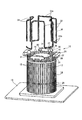
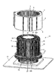
- FIG. 2 is a plan view and aa cross-sectional view showing a stator manufacturing apparatus according to an embodiment of the present invention.
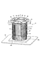
- FIG. 4 is a plan view and a bb sectional view showing a structure in which a guide member is provided in the structure of FIG.
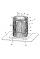
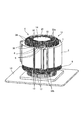
- the top view and cc sectional drawing which show the state which has arrange
- FIG. 6 is a view corresponding to the cc cross section of FIG. 5 (A), showing a state in which the guide member is removed and a pin which is the other end side restricting member is mounted.
- positions a coil to a stator core by the manufacturing apparatus of the stator which concerns on embodiment of this invention The perspective view which similarly shows a 2nd process.
- the stator 1 constitutes an electric motor (including a generator) together with a rotor, and the electric motor is suitable for application to an electric motor (including a generator) serving as a drive source for electric vehicles and hybrid vehicles, particularly a brushless DC motor. is there.
- the stator 1 includes a stator core 2 in which a large number of thin silicon steel plates are laminated, and a coil 4 around which a magnet wire (conductor, winding) 3 that is a predetermined material is wound.
- the stator core 2 is formed in a ring shape, and a plurality of slots 5 and teeth 6 that are open on the inner diameter side are alternately formed.
- the three-phase U, V, W coils 4 (4U, 4V, 4W) are wound between the two slots 5 separated by a predetermined pitch by distributed winding.
- the magnet wire 3 is formed of a rectangular wire having a rectangular cross section, and an insulating film such as an insulating resin is formed on the entire circumference of the conductor portion made of copper or the like.
- the three-phase coils 4U, 4V, 4W made of the wires 3 are arranged in the same-phase slot 5 in which a plurality of (for example, four) wires 3 having the same phase are arranged side by side in the radial direction of the stator core 2.
- one end side coil end portion 8 protruding from one end surface 7 (upper end surface in FIG.
- the U-phase coil 4U is adjacent to the coil 4U in such a way that two sets 4U1 and 4U2 are set so as to occupy two adjacent slots 5 and 5, as shown in FIG.
- the two slots 5 and 5 are configured so that the closer and far sides of the two slots 5 and 5 are connected at a predetermined interval and the two sets are connected alternately.
- Each set of coils 4U1 and 4U2 projects from the slot conductor portion 11 disposed in the slot 5 and the slot conductor portion 11 protruding from one end surface 7 of the stator core 2 and spaced apart by a predetermined distance in the inner diameter direction R1.
- the one end side coil end portion 8 (the upper coil end portion in FIG.
- both the coil end portions 8 and 10 are bent (bent) in a circumferential direction (for example, Y) or an axial direction (for example, X) to be aligned without interfering with each other in the axial direction L or the radial direction R. ing.
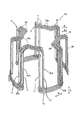
- Each rectangular wire W constituting the coil 4 includes a plurality of straight portions 32, a plurality of continuous portions 33a and 33b, and a plurality of bent portions 34, and is formed in a substantially cylindrical shape as a whole.
- Each of these linear portions 32 corresponds to the above-described slot conductor portion 11 and is disposed in each slot 5 of the stator core 2, and is formed in parallel with each slot 5.
- the continuous portions 33a and 33b are ones in which one end portion and the other end portion of the adjacent linear portions 32 are alternately continued, and are bent at right angles from the end portions of the linear portions 32. Is formed.
- Each bent portion 34 is formed by bending one end of each linear portion 32 radially inward.
- the continuous portions 33a and 33b and the bent portions 34 correspond to the coil end portions 8 and 10 described above.
- each bent portion 34 are continuous by the continuous portion 33a on the one end side, and the continuous portion 33a on the one end side exists inward in the radial direction with respect to each linear portion 32.
- the continuous portion 33b on the other end side is located on the same circumference connecting the straight portions 32, or is located radially outward from the straight portions 32.
- a stator manufacturing apparatus 12 in which the coil 4 as described above is arranged on the stator core 2 will be described with reference to FIGS.
- the manufacturing apparatus 12 is formed by fixing an insertion jig 14 made of a material having sufficient rigidity such as stainless steel on a substrate 13.
- the insertion jig 14 is formed in a substantially cylindrical shape as a whole, and a rectangular wire W constituting the winding of the coil 4 (magnet wire 3) is detachable in the axial direction (see FIGS. 5 to 15 described later). ).
- the insertion jig 14 includes a plurality of protrusions 15 provided so as to protrude in a radial direction at a plurality of locations on the outer peripheral surface, and one end side in the axial direction from a portion removed from each protrusion 15 in the circumferential direction. ⁇ Fig. 3B, Fig. 4B, Fig. 5B, Fig. 6 ⁇ are provided.
- Each of these protrusions 15 is provided at a position aligned with the slot 5 of the stator core 2 to be inserted. Therefore, the protrusions 15 have the same phase and the same number as the slots 5 in the circumferential direction.
- Each protrusion 15 extends in the axial direction of the insertion jig 14 in the axial direction ⁇ vertical direction in FIGS. 3B, 4B, 5B, and 6 ⁇ .
- the orthogonal cross section is formed to be a rectangle. Further, the direction of the side surface on the outer diameter side of each projection 15 is made to correspond to the direction in which each slot 5 is formed.
- each slot 5 is the radial direction of the stator core 2
- the side surface on the outer diameter side of each projection 15 is a surface orthogonal to the radial direction.
- the side surface (outer peripheral surface) on the outer diameter side is made slippery than the surface of each slot 5 of the stator core 2 by improving the surface roughness, etc. It is preferable to facilitate the attachment / detachment of 32.
- each protrusion 15 is set to be slightly larger than the diameter of the inscribed circle of each tooth 6 of the stator core 2. And, as will be described later, a state in which the radially inner side surface of each linear portion 32 constituting the rectangular wire W having the innermost diameter among the rectangular wires W arranged to overlap each protrusion 15 is arranged in each slot 5. Then, it is positioned radially outward from the tip surface of each of the teeth 6. Thereby, for example, a magnetic wedge is arranged in the opening of each slot 5, or a creeping distance between each straight portion 32 and the tip surface of each tooth 6 is secured.
- each protrusion 15 is adjusted according to the radial position in each slot 5 of the rectangular wire W existing at the innermost diameter of the coil 4.
- the circumferential width of each protrusion 15 is slightly smaller than the circumferential width of each slot 5.
- a portion of the outer peripheral surface of the insertion jig 14 that is detached from the projections 15 is a recess 17.
- the diameter of the circumscribed circle of the bottom surface of each recess 17 is slightly smaller than the diameter of the inscribed circle of each tooth 6, and the circumferential width of each recess 17 is the circumferential direction of each tooth 6. It is slightly larger than the width.
- the teeth 6 can be arranged in the recesses 17.
- the rectangular wire W formed in a cylindrical shape and the stator core 2 are arranged on the outer peripheral surface of the insertion jig 14. In this case, the cylindrical center of the rectangular wire W and the cylindrical center of the inner peripheral surface of the stator core 2 can be accurately matched, and the rectangular wire W is radially inserted into each slot 5 of the stator core 2. Evenly arranged without variation.
- each protruding pin 16 is arranged on the inner diameter side of the inscribed circle of the teeth 6 on one end surface in the axial direction of the insertion jig 14. That is, each protruding pin 16 has a circumscribed circle having a diameter equal to or smaller than the inscribed circle on the bottom surface of each recessed portion 17 at a position aligned with each recessed portion 17. Each is provided. Further, the protruding amount of each protruding pin 16 in the axial direction is such that, as shown in FIGS. 11 to 15 to be described later, all the rectangular wires W are arranged in the insertion jig 14 to form the coil 4.
- the protruding amount of each protruding pin 16 is an amount that allows for a portion for fixing the guide member 29, as will be described later.
- each protruding pin 16 since the diameter of each protruding pin 16 is smaller than the circumferential width of each recess 17, the position in the circumferential direction is set to the circumference of each recess 17.
- the flat wire W is attached by shifting from the central position in the direction to one side, the circumferential side surfaces of the bent portions 34 of the flat wire W are brought into contact with or close to the protruding pins 16.
- each protruding pin 16 is shifted from the circumferential center position of each recess 17 in the counterclockwise direction of FIG.
- each protruding pin 16 is It arrange
- a member having the same width as the circumferential width of the teeth 6 may be provided.
- a cylindrical protruding cylindrical portion 18 protruding in the axial direction is fixed to the central portion of the axial end surface of the insertion jig 14. That is, the inner peripheral surface of the projecting cylindrical portion 18 is fitted to a columnar portion 19 provided at the center of one end surface in the axial direction of the insertion jig 14, and the projecting cylindrical portion 18 and the insertion jig 15 are connected by bolts or the like. Is fixed to one end face in the axial direction.
- the diameter of the outer peripheral surface of the projecting cylindrical portion 18 is the same as or slightly smaller than the diameter of the inscribed circle of the one end side coil end portion 8 of the coil 4 (the inscribed circle of the continuous portion 33a having the innermost diameter). To make it smaller.
- a guide plate 21 having an outer peripheral surface formed in a partial conical shape is fixed to one end surface of the protruding cylindrical portion 18 with a bolt or the like. Then, the one end side of the flat wire W is guided to a predetermined position by the outer peripheral surface of the guide plate 21.
- the insertion jig 14 fixes a cylindrical main body portion 23 having projections 15 formed on the outer peripheral surface and a lid portion 24 for fixing the protruding cylindrical portion 18 with bolts or the like.
- these may be formed integrally.
- the members 23, 24, and 18 may be integrally formed.
- a pin 27 (for example, see FIG. 6), which will be described later, is fitted at a position aligned with each of the recesses 17 on the outer circumferential surface on the other axial end side of the outer circumferential surface of the insertion jig 14.
- Fitting holes 28 for fixing together are formed respectively.
- the axial position where each pin 27 is fixed (that is, the axial position of the fitting hole 28) is from the other end face 9 of the stator core 2 in a state where the stator core 2 is disposed in the insertion jig 14, as will be described later.
- each fitting hole 28 has a bottomed cylindrical shape, and fixes each pin 27 by interference fitting. However, the tightening margin is reduced to facilitate the attachment / detachment of the pins 27.
- the diameter of each pin 27 is the same as or smaller than the circumferential width of each recess 17.
- guide members 29 are arranged at a plurality of positions on one end side in the axial direction of the insertion jig 14. As shown in FIG. 4A, eight guide members 29 are arranged side by side in the circumferential direction of the insertion jig 14. And the inclined surface 30 which the width
- each positioning protrusion 31 is formed on the other axial end surface of each guide member 29 so as to protrude to the other side in the axial direction.
- Each positioning protrusion 31 has a width in the circumferential direction that is substantially the same as the interval of each protruding pin 16 in the circumferential direction.
- the positioning protrusions 31 are arranged between the protruding pins 16 to position the guide members 29 in the circumferential direction.
- a bottomed cylindrical fitting hole for fitting and fixing each protruding pin 16 is provided at a plurality of locations on the other axial end surface of each guide member 29, and each protruding pin 16 is provided in each fitting hole.
- Each guide member 29 is fixed at a predetermined position of the insertion jig 14 by fitting and fixing the distal end portion thereof. In addition, the tightening allowance between each fitting hole and each projecting pin 16 is also reduced, so that each guide member 29 can be easily attached and detached. Then, as will be described later, each of the guide members 29 is alternately fixed to a position suitable for the insertion position of the flat wire W, and separation of the portion deviating from the suitable position is repeated alternately to insert the flat wire W. Mount on the jig 14.
- the rectangular wire W constituting the coil 4 is divided every round, and as shown in FIGS. 7 to 15, each rectangular wire W is sequentially placed on one end side of the insertion jig 14 ( It is mounted in the axial direction from the upper side of FIGS. 7 to 15 to the other end side (lower side of FIGS. 7 to 15).
- each guide member 29 is first arranged at a predetermined position on one end side of the insertion jig 14, as shown in FIG.
- the positions where the guide members 29 are arranged are positions where the protrusions 15 to which the straight portions 32 of the flat wire W are to be attached exist on both sides in the circumferential direction of the guide members 29, and It is set as the position which the phase of the circumference direction shifted
- the flat wire W is connected from one end side of the insertion jig 14 with the continuous portion 33 b on the other end side of the flat wire W positioned between the guide members 29. Move in the axial direction toward the other end. At this time, each linear portion 32 is guided by the inclined surface 30 of each guide member 29, moves on the outer side surface of the predetermined protrusion 15, and is arranged so as to overlap the side surface in the radial direction. Is done.
- the remaining four guide members 29 are also inserted as shown in FIG.
- the jig 14 is disposed on one end side.
- the remaining guide members 29 are also arranged so that the protrusions 15 to which the linear portions 32 are to be attached exist on both sides.
- the linear portions 32 are arranged between the guide members 29, and the linear portions 32 are mounted on the insertion jig 14 while being guided by the guide members 29.
- the rectangular wire W is moved to a predetermined position of the insertion jig 14, and the bent portions 34 are arranged between the protruding pins 16.
- the mounting position of the flat wire W is a position where each of the bent portions 34 comes into contact with one end surface of the insertion jig 14. That is, the position of the rectangular wire W in the axial direction with respect to the insertion jig 14 is regulated by bringing the bent portions 34 into contact with one end surface of the insertion jig 14.
- each rectangular wire W constituting the winding of the coil 4 is sequentially repeated for each rectangular wire W constituting the winding of the coil 4.
- the side surface on the outer diameter side of each straight line portion 32 constituting each flat wire W is brought into contact with the side surface on the inner diameter side of each straight portion 32 of the flat wire W to be mounted next.
- the position of each guide member 29 is moved in accordance with the position of each projection 15 to which each linear portion 32 is to be attached.
- the rectangular wire W is arranged in the insertion jig 14 so as to be distributed winding, and the coil 4 is formed of the U phase, the V phase, and the W phase. Then, as shown in FIG.
- each linear portion 32 is disposed between the pins 27, and the circumferential position of the other axial end of each linear portion 32 is regulated.
- the stator core 2 is arranged on one end side of the insertion jig 14, and the straight portions 32 and the slots 5 of the stator core 2 are aligned with each other in FIG.
- the stator core 2 is moved from one end side to the other end side of the insertion jig 14, and the stator core 2 is externally fitted to the insertion jig 14.
- the insertion jig 14 is inserted into the stator core 2 from one end side.
- the straight portions 32 are arranged in the slots 5.
- the pins 27 are removed from the insertion jig 14. Then, by lifting the stator core 2 together with the coil 4 composed of the rectangular wire W from the insertion jig 14 to one end side, in other words, pulling the insertion jig 14 from the stator core 2 to the other end side. Thus, the stator core 2 on which the coil 4 is disposed and the insertion jig 14 are separated. Thereby, each said linear part 32 is arrange
- the rectangular wire W is distributed in the stator core 2 by inserting the rectangular wire W into the insertion jig 14 so as to be distributed and then inserting the rectangular wire W into the stator core 2 in the axial direction.
- the work to arrange by winding can be done easily. That is, the rectangular wire W is arranged in advance so as to be distributed winding on the insertion jig 14, and the radial position of each linear portion 32 to be inserted into each slot 5 is set in the circumferential direction by each projection 15. Since the position is regulated by the protruding pins 16 and the pins 27, the linear portions 32 are not displaced in the circumferential direction when the insertion jig 14 is inserted into the stator core 2 in the axial direction.
- the straight portions 32 can be easily arranged at predetermined positions in the radial direction of the slots 5.
- each linear portion 32 can be easily determined by overlapping each linear portion 32 on each protrusion 15. That is, since the rectangular wire W has a rectangular cross section, each straight line W is brought into contact with the outer diameter side surface of each projection 15 so as to overlap the inner diameter side surface of each linear portion 32. The direction of the part 32 is determined automatically. Further, if the side surface on the outer diameter side of each linear portion 32 is brought into contact with the side surface on the inner diameter side of each linear portion 32 of the rectangular wire W to be mounted next, each side to be mounted next The direction of the straight line portion 32 is naturally determined. Therefore, if the direction of the side surface on the outer diameter side of each protrusion 15 is made to correspond to the direction in which each slot 5 is formed, the direction of each linear portion 32 can be easily regulated. The inner surface of each slot 5 can be parallel.
- each linear portion 32 in the circumferential direction can be easily regulated by the protruding pins 16 using the bent portions 34. That is, since each bent portion 34 is formed by bending one end side of each linear portion 32, if the position in the circumferential direction of each bent portion 34 is restricted, the circumference of each linear portion 32 is determined. The position of the direction can also be easily regulated.
- the circumferential position restriction on one end side of each linear portion 32 is, for example, the other end. If it carries out similarly to the pin 27 of the side, it will interfere with the stator core 2 at the time of insertion. For this reason, the structure similar to the other end side cannot be adopted. On the other hand, if each of the bent portions 34 is used, the insertion jig 14 can be inserted without causing interference with the stator core 2.
- each linear portion 32 since the circumferential position on the other end side of each linear portion 32 is regulated by each pin 27, the circumferential position of each linear portion 32 is more reliably set in the axial direction. Therefore, when the insertion jig 14 is inserted into the stator core 2, the linear portions 32 and the slots 5 of the stator core 2 can be prevented from interfering with each other, and the insertion operation can be performed smoothly. That is, the rectangular wire W has high circumferential rigidity due to the presence of the continuous portions 33a and 33b. Therefore, when each straight line portion 32 is disposed to be inclined in the circumferential direction with respect to each slot 5, the inclination of each straight line portion 32 is difficult to return.
- each straight line portion 32 When the insertion work is performed while the straight portions 32 are inclined, the straight portions 32 and the slots 5 interfere with each other, so that the insertion work cannot be performed smoothly and the straight portions 32 are damaged. May occur. On the other hand, if the circumferential position of each straight line portion 32 is restricted between the one end side and the other end side in the axial direction as in the present embodiment, the inclination of each straight line portion 32 is less likely to occur. It is possible to make the above-described problems difficult to occur.
- each pin 27 is removed from the insertion jig 14, so that the continuous portion 33 b on the other end side of the rectangular wire W interferes with each pin 27. There is nothing. Further, since each linear portion 32 and each bent portion 34 are guided to predetermined positions by the respective guide members 29, the mounting operation of the flat wire W to the insertion jig 14 can be easily and reliably performed. That is, in order to perform the mounting work of the rectangular wire W while guiding the straight portions 32 between the guide members 29, the phase with the protrusions 15 to which the straight portions 32 should be mounted is easily set. Furthermore, it is possible to prevent the straight portions 32 from being detached from the protrusions 15 by being inclined or the like at the time of mounting.
- each protrusion pin 16, each pin 27, and each guide member 29 is not limited to the structure shown by the above-mentioned embodiment, It is good also as another shape which can acquire the same effect.
- the protruding pins 16 and the pins 27 may be formed in a substantially rectangular shape so that the side surfaces thereof are along the side surfaces of the bent portions 34 or the linear portions 32.
- Each rectangular wire W constituting the coil 4 may be a plurality of wound wires, or may be less than one turn, for example, a two-third turn. However, it is made larger than half a circle so that it can be externally attached to the insertion jig 14.
- the stator manufacturing apparatus can be used to manufacture a stator of a motor, and is particularly suitable for a structure in which rectangular wires are arranged in a distributed winding like a motor stator for a hybrid vehicle. .
Landscapes
- Engineering & Computer Science (AREA)
- Manufacturing & Machinery (AREA)
- Power Engineering (AREA)
- Manufacture Of Motors, Generators (AREA)
Abstract
Description
コイルの巻線(3)を構成し、前記各スロット(5)内に配置される該各スロット(5)と平行な複数の直線部(32)と、隣り合う各直線部(32)の一端部同士と他端部同士とを交互に連続させる複数の連続部(33a,33b)と、前記各直線部(32)の一端側を径方向内方に折り曲げた複数の折り曲げ部(34)とを有し、全体を略円筒状に形成した断面矩形の平角線(W)と、を備え、該平角線(W)を前記ステータコア(2)に分布巻きで配置してなるステータの製造装置において、
全体を略円筒状に形成し、前記平角線(W)を軸方向に着脱自在とした挿入治具(14)を備え、
前記挿入治具(14)は、外周面の前記各スロット(5)に整合する複数個所に径方向に突出するように設けられた突部(15)と、円周方向の該各突部(15)から外れた位置で前記ステータコア(2)の前記各スロット(5)の間部分に存在するティース(6)の内接円よりも内径側に、軸方向一端側にそれぞれ突出するように設けられた一端側規制部材(16)と、を有し、
前記平角線(W)を前記挿入治具(14)の一端側から配置し、前記各直線部(32)を前記各突部(15)に径方向に重ねることにより該各直線部(32)の径方向位置を規制すると共に、前記各折り曲げ部(34)を前記各一端側規制部材(16)の間に配置することにより前記各直線部(32)の円周方向位置を規制し、該各直線部(32)と前記各スロット(5)とを整合させた状態で、前記挿入治具(14)を、一端側から前記ステータコア(2)内に挿入し、該ステータコア(2)から他端側に引き抜くことにより、前記各スロット(5)内の所定位置に前記各直線部(32)を配置可能としたことを特徴とするものである。
前記平角線(W)を前記挿入治具(14)に配置してから、前記各他端側規制部材(27)を該挿入治具(14)に装着し、該各他端側規制部材(27)により前記各直線部(32)の他端側の円周方向位置を規制した状態で、前記挿入治具(14)を前記ステータコア(2)内に挿入し、前記各他端側規制部材(27)を該挿入治具(14)から外して、該挿入治具(14)を該ステータコア(2)から引き抜く。
2 ステータコア
3 巻線(マグネットワイヤ)
4 コイル
5 スロット
6 ティース
7 一端面
8 一端側コイルエンド部
9 他端面
10 他端側コイルエンド部
11 スロット導体部
12 製造装置
13 基板
14 挿入治具
15 突部
16 一端側規制部材(突出ピン)
17 凹部
18 突出円筒部
19 円柱部
20 ボルト
21 案内板
23 本体部
24 蓋部
27 他端側規制部材(ピン)
28 嵌合孔
29 ガイド部材
30 傾斜面
31 位置決め突部
32 直線部
33a,33b 連続部
34 折り曲げ部
W 平角線
Claims (3)
- それぞれが内周面に開口するように径方向に形成されたスロットを円周方向複数個所に有するステータコアと、
コイルの巻線を構成し、前記各スロット内に配置される該各スロットと平行な複数の直線部と、隣り合う各直線部の一端部同士と他端部同士とを交互に連続させる複数の連続部と、前記各直線部の一端側を径方向内方に折り曲げた複数の折り曲げ部とを有し、全体を略円筒状に形成した断面矩形の平角線と、を備え、該平角線を前記ステータコアに分布巻きで配置してなるステータの製造装置において、
全体を略円筒状に形成し、前記平角線を軸方向に着脱自在とした挿入治具を備え、
前記挿入治具は、外周面の前記各スロットに整合する複数個所に径方向に突出するように設けられた突部と、円周方向の該各突部から外れた位置で前記ステータコアの前記各スロットの間部分に存在するティースの内接円よりも内径側に、軸方向一端側にそれぞれ突出するように設けられた一端側規制部材と、を有し、
前記平角線を前記挿入治具の一端側から配置し、前記各直線部を前記各突部に径方向に重ねることにより該各直線部の径方向位置を規制すると共に、前記各折り曲げ部を前記各一端側規制部材の間に配置することにより前記各直線部の円周方向位置を規制し、該各直線部と前記各スロットとを整合させた状態で、前記挿入治具を、一端側から前記ステータコア内に挿入し、該ステータコアから他端側に引き抜くことにより、前記各スロット内の所定位置に前記各直線部を配置可能としたことを特徴とするステータの製造装置。 - 前記挿入治具は、軸方向他端側外周面の前記各突部から外れた位置に、径方向に突出するように着脱自在に設けた他端側規制部材を備え、
前記平角線を前記挿入治具に配置してから、前記各他端側規制部材を該挿入治具に装着し、該各他端側規制部材により前記各直線部の他端側の円周方向位置を規制した状態で、前記挿入治具を前記ステータコア内に挿入し、前記各他端側規制部材を該挿入治具から外して、該挿入治具を該ステータコアから引き抜く、請求項1に記載したステータの製造装置。 - 前記挿入治具の軸方向一端側に配置され、前記各直線部を所定の突部に案内すると共に、前記各折り曲げ部を所定の一端側規制部材の間に案内するガイド部材を備えた、請求項1又は2に記載のステータの製造装置。
Priority Applications (2)
| Application Number | Priority Date | Filing Date | Title |
|---|---|---|---|
| CN201080003691.0A CN102257706B (zh) | 2009-03-23 | 2010-02-03 | 定子的制造装置 |
| DE112010000063T DE112010000063T5 (de) | 2009-03-23 | 2010-02-03 | Statorherstellungsvorrichtung |
Applications Claiming Priority (2)
| Application Number | Priority Date | Filing Date | Title |
|---|---|---|---|
| JP2009070995A JP5083257B2 (ja) | 2009-03-23 | 2009-03-23 | ステータの製造装置 |
| JP2009-070995 | 2009-03-23 |
Publications (1)
| Publication Number | Publication Date |
|---|---|
| WO2010109747A1 true WO2010109747A1 (ja) | 2010-09-30 |
Family
ID=42736216
Family Applications (1)
| Application Number | Title | Priority Date | Filing Date |
|---|---|---|---|
| PCT/JP2010/000654 Ceased WO2010109747A1 (ja) | 2009-03-23 | 2010-02-03 | ステータの製造装置 |
Country Status (5)
| Country | Link |
|---|---|
| US (1) | US8256100B2 (ja) |
| JP (1) | JP5083257B2 (ja) |
| CN (1) | CN102257706B (ja) |
| DE (1) | DE112010000063T5 (ja) |
| WO (1) | WO2010109747A1 (ja) |
Families Citing this family (8)
| Publication number | Priority date | Publication date | Assignee | Title |
|---|---|---|---|---|
| JP5278555B2 (ja) * | 2011-03-08 | 2013-09-04 | トヨタ自動車株式会社 | モータ製造方法 |
| WO2012120646A1 (ja) * | 2011-03-08 | 2012-09-13 | トヨタ自動車株式会社 | モータ製造方法 |
| JP2013135527A (ja) * | 2011-12-26 | 2013-07-08 | Asmo Co Ltd | ステータの製造方法、ステータの製造装置及びステータ |
| JP5920258B2 (ja) * | 2013-03-19 | 2016-05-18 | 株式会社安川電機 | コイル製造用巻線部材、コイル、回転電機およびコイルの製造方法 |
| EP2824811A1 (de) * | 2013-07-11 | 2015-01-14 | Siemens Aktiengesellschaft | Durchgehende, auf Spulenträger gewickelte Statorwicklung |
| US11557941B2 (en) | 2019-03-14 | 2023-01-17 | Robert C. Hendricks | Electronically commutated axial conductor motor |
| WO2020195311A1 (ja) * | 2019-03-27 | 2020-10-01 | 日本電産株式会社 | ステータの製造方法及びステータ |
| EP3890170B1 (en) * | 2020-04-03 | 2025-07-02 | Wobben Properties GmbH | System for assembling a generator, generator vertical assembly device and corresponding assembling method |
Citations (3)
| Publication number | Priority date | Publication date | Assignee | Title |
|---|---|---|---|---|
| JPS5932343A (ja) * | 1982-08-13 | 1984-02-21 | Hitachi Ltd | コイル插入装置 |
| JP2003088021A (ja) * | 2001-09-17 | 2003-03-20 | Mitsubishi Electric Corp | 交流発電機の固定子およびその製造方法 |
| JP2003153478A (ja) * | 2001-11-08 | 2003-05-23 | Mitsubishi Electric Corp | 回転電機の固定子およびその製造方法 |
Family Cites Families (7)
| Publication number | Priority date | Publication date | Assignee | Title |
|---|---|---|---|---|
| US3402462A (en) * | 1965-10-23 | 1968-09-24 | Industra Products | Process and apparatus for assembling coils |
| US3815206A (en) * | 1972-12-04 | 1974-06-11 | Gen Electric | Wire protecting coil placing method and apparatus |
| US3949464A (en) * | 1975-01-13 | 1976-04-13 | Industra Products, Inc. | Contemporaneous insertion of overlapping coils |
| US4276689A (en) * | 1979-04-05 | 1981-07-07 | General Electric Company | Apparatus and method for axial insertion of dynamoelectric machine end turn insulation |
| US4538349A (en) * | 1982-08-13 | 1985-09-03 | Hitachi, Ltd. | Coil fitting system |
| US5237740A (en) * | 1990-08-30 | 1993-08-24 | Nippondenso Co., Ltd. | Coil insertion device |
| US5802706A (en) * | 1995-08-21 | 1998-09-08 | General Electric Company | Apparatus for injecting stator winding coil groups into a stator core |
-
2009
- 2009-03-23 JP JP2009070995A patent/JP5083257B2/ja not_active Expired - Fee Related
-
2010
- 2010-02-03 WO PCT/JP2010/000654 patent/WO2010109747A1/ja not_active Ceased
- 2010-02-03 DE DE112010000063T patent/DE112010000063T5/de not_active Withdrawn
- 2010-02-03 CN CN201080003691.0A patent/CN102257706B/zh not_active Expired - Fee Related
- 2010-03-09 US US12/719,906 patent/US8256100B2/en not_active Expired - Fee Related
Patent Citations (3)
| Publication number | Priority date | Publication date | Assignee | Title |
|---|---|---|---|---|
| JPS5932343A (ja) * | 1982-08-13 | 1984-02-21 | Hitachi Ltd | コイル插入装置 |
| JP2003088021A (ja) * | 2001-09-17 | 2003-03-20 | Mitsubishi Electric Corp | 交流発電機の固定子およびその製造方法 |
| JP2003153478A (ja) * | 2001-11-08 | 2003-05-23 | Mitsubishi Electric Corp | 回転電機の固定子およびその製造方法 |
Also Published As
| Publication number | Publication date |
|---|---|
| JP2010226862A (ja) | 2010-10-07 |
| US8256100B2 (en) | 2012-09-04 |
| DE112010000063T5 (de) | 2012-06-14 |
| JP5083257B2 (ja) | 2012-11-28 |
| CN102257706A (zh) | 2011-11-23 |
| CN102257706B (zh) | 2013-07-03 |
| US20100236059A1 (en) | 2010-09-23 |
Similar Documents
| Publication | Publication Date | Title |
|---|---|---|
| JP5083257B2 (ja) | ステータの製造装置 | |
| US9203274B2 (en) | Electromagnet for stator and manufacturing method of electromagnet for stator | |
| US8269387B2 (en) | Coil for rotating electric machine having bent drawn-out ends | |
| CN102549892B (zh) | 定子的制造方法以及制造装置 | |
| KR100923463B1 (ko) | 발전기기 고정자 및 그것에 예비권선 코일을 설치하는 방법 | |
| US10164493B2 (en) | Stator and brushless motor | |
| JP6576549B2 (ja) | 電機子の製造方法、回転電機の製造方法、および電機子の製造装置 | |
| JP5738385B2 (ja) | 固定子およびその固定子を備えた回転電機 | |
| CN106663997A (zh) | 定子制造方法以及定子 | |
| CN105375668A (zh) | 用于旋转电机的定子 | |
| US20150372573A1 (en) | Method and apparatus for forming a concentric winding coil | |
| WO2020174817A1 (ja) | 回転電機のステータ、回転電機、回転電機のステータの製造方法、および、回転電機の製造方法 | |
| JP7394396B2 (ja) | ステータ及びそれを用いたモータ | |
| JP2007318874A (ja) | 回転電機の巻線端部成形装置および成形方法 | |
| JP5181627B2 (ja) | 回転電機および回転電機の製造方法 | |
| US9013085B2 (en) | Method for producing a stator winding of an electric machine, in particular an alternator | |
| JP5458627B2 (ja) | ステータの製造方法及び製造装置 | |
| JP5563876B2 (ja) | コイルの製造方法およびモータ | |
| JP5381213B2 (ja) | ステータの製造方法及び平角線の製造装置 | |
| JP5496159B2 (ja) | 円筒型リニアモータ及び円筒型リニアモータの固定子コイルの巻装方法 | |
| CN114256997B (zh) | 旋转电机和旋转电机的定子绕组的制造方法 | |
| JP5262868B2 (ja) | ステータの製造方法 | |
| JP2013021858A (ja) | モータ製造方法 | |
| JP5915150B2 (ja) | ヘリカル巻シート状コイル | |
| JP2019187072A (ja) | 捻り加工装置 |
Legal Events
| Date | Code | Title | Description |
|---|---|---|---|
| WWE | Wipo information: entry into national phase |
Ref document number: 201080003691.0 Country of ref document: CN |
|
| 121 | Ep: the epo has been informed by wipo that ep was designated in this application |
Ref document number: 10755556 Country of ref document: EP Kind code of ref document: A1 |
|
| WWE | Wipo information: entry into national phase |
Ref document number: 1120100000638 Country of ref document: DE Ref document number: 112010000063 Country of ref document: DE |
|
| 122 | Ep: pct application non-entry in european phase |
Ref document number: 10755556 Country of ref document: EP Kind code of ref document: A1 |