WO2010107046A1 - 薬液供給装置 - Google Patents
薬液供給装置 Download PDFInfo
- Publication number
- WO2010107046A1 WO2010107046A1 PCT/JP2010/054507 JP2010054507W WO2010107046A1 WO 2010107046 A1 WO2010107046 A1 WO 2010107046A1 JP 2010054507 W JP2010054507 W JP 2010054507W WO 2010107046 A1 WO2010107046 A1 WO 2010107046A1
- Authority
- WO
- WIPO (PCT)
- Prior art keywords
- chemical solution
- chemical liquid
- chemical
- container
- discharged
- Prior art date
- Legal status (The legal status is an assumption and is not a legal conclusion. Google has not performed a legal analysis and makes no representation as to the accuracy of the status listed.)
- Ceased
Links
Images





Classifications
-
- E—FIXED CONSTRUCTIONS
- E03—WATER SUPPLY; SEWERAGE
- E03D—WATER-CLOSETS OR URINALS WITH FLUSHING DEVICES; FLUSHING VALVES THEREFOR
- E03D9/00—Sanitary or other accessories for lavatories ; Devices for cleaning or disinfecting the toilet room or the toilet bowl; Devices for eliminating smells
- E03D9/02—Devices adding a disinfecting, deodorising, or cleaning agent to the water while flushing
- E03D9/03—Devices adding a disinfecting, deodorising, or cleaning agent to the water while flushing consisting of a separate container with an outlet through which the agent is introduced into the flushing water, e.g. by suction ; Devices for agents in direct contact with flushing water
- E03D9/032—Devices connected to or dispensing into the bowl
Definitions
- This invention relates to the chemical
- toilet bowls that do not have a hand-washing section at the top of the tank or a toilet bowl that does not have a water storage tank itself are on the market.
- the chemical solution supply device described in Patent Document 1 is provided with a chemical solution bottle so as to be hung on a rim of a toilet bowl, and a plate for receiving the chemical solution is attached below the bottle.
- medical solution is supplied to the inner wall face of a toilet bowl by exposing the chemical
- an aroma effect can also be obtained by the aroma component contained in the chemical solution.
- the chemical solution supply apparatus as described above is attached to the rim of the toilet bowl, the flowing water at the time of flushing rarely contacts the apparatus. Therefore, it can be said that the apparatus is not cooled by running water and the temperature change of the apparatus itself is small. For this reason, the discharge of the chemical liquid mainly depends on the mechanism of the apparatus, but it has been difficult to achieve an appropriate discharge amount with the above-described chemical liquid discharge apparatus, and an improvement has been demanded.
- the present invention has been made in order to solve the above-described problem, and an object thereof is to provide a chemical solution supply apparatus that can be attached to a toilet rim and can discharge an appropriate amount of chemical solution.
- the present invention is a chemical liquid supply device attached to a toilet rim, containing a chemical liquid having a predetermined viscosity, connected to the chemical liquid container having a chemical liquid discharge port, and the chemical liquid container, A chemical solution discharge mechanism for guiding the chemical solution to the outside, a support member for supporting the chemical solution discharged from the chemical solution discharge mechanism, and a suspension for hanging the chemical solution container, the drug discharge mechanism, and the support member on the rim of the toilet bowl A chemical solution discharging mechanism, wherein the chemical solution discharge mechanism is discharged from the chemical solution container, a buffer space that stores the chemical solution discharged from the chemical solution container, at least one air circulation hole that communicates the buffer space with the outside air.
- the And outlet holes, the chemical liquid is discharged from the outlet hole is provided, and a plate-like projection extending toward the support member.
- the chemical liquid discharged from the chemical liquid container flows into the buffer space and the discharge flow path of the chemical liquid discharge mechanism.
- the pressure in the chemical solution container becomes negative, so that the chemical solution is difficult to be discharged.
- the present invention when a negative pressure is generated in the chemical liquid container, air or chemical liquid flows from the buffer space into the chemical liquid container, so that the chemical liquid can be pushed out to the discharge channel. Therefore, the chemical solution can be discharged smoothly.
- the opening area of the largest communication hole among the plurality of communication holes is preferably 0.6 to 1.8 mm 2 . Further, when one communication hole is formed, the opening area is preferably 0.9 to 1.8 mm 2 . This is for the following reason.
- the opening area of the communication hole is preferably 1.8 mm 2 or less.
- the largest communication hole is likely to have an influence, and therefore the opening area of the largest communication hole is preferably 1.8 mm 2 or less.
- the opening area of the communication hole is small, the amount of air or the chemical liquid flowing from the buffer space to the chemical liquid container becomes small, and the chemical liquid in the chemical liquid container cannot be pushed out to the discharge channel. Therefore, the chemical solution cannot be discharged smoothly. Therefore, when a plurality of communication holes are formed, the opening area of the largest communication hole is preferably 0.6 mm 2 or more. However, when there is one communication hole, it is preferably 0.9 mm 2 or more, which is larger than this. This is because it is necessary to reliably exhibit the function of the communication hole described above with one communication hole. Further, since the communication hole is very small, it is necessary to surely exhibit the above function even when variations in molding occur.
- the outer peripheral edge of the communication hole can be configured by a curve. By doing so, the chemical solution and air can easily pass.
- a plate-like protrusion that is supplied with the chemical solution discharged from the outflow hole and extends toward the support member can be further provided, and the protrusion includes a plurality of grooves that extend from the outflow hole side to the support member side. Can be formed.
- a protrusion part can take a various structure, for example, it can be comprised so that two or more protrusion parts may be provided or it may extend radially centering on an outflow hole. If comprised in this way, a chemical
- the radial form here does not need to extend the projecting part in all directions of 360 °, and it is sufficient that the projecting part is arranged over a part thereof, in particular, a predetermined angle facing the rim side. .
- the chemical liquid discharged from the outflow hole can be easily guided to the support member, and the chemical liquid can be discharged smoothly.
- the flow of the chemical solution can be promoted by capillary action, and even a high-viscosity chemical solution can be discharged more smoothly. Can do.
- the support member can be configured to support the chemical solution discharged from the chemical solution discharge mechanism so as to be in contact with running water flowing in the toilet. Thereby, since the discharged
- the chemical solution container can be attached to the rim of the toilet bowl that is not disposed in the flow path of the flushing water.
- the support member can be formed with at least one through hole facing the toilet. By doing so, even if the chemical solution is not exposed by running water, the chemical solution supplied to the support member can be discharged to the toilet through the through hole.
- an object is to provide a chemical liquid supply apparatus capable of discharging an appropriate amount of chemical liquid.
- FIG. 2 is an exploded rear view of the chemical solution supply apparatus of FIG. 1.
- FIG. 2 is an exploded side view of the chemical solution supply apparatus of FIG. 1.
- FIG. 6 is a cross-sectional view taken along line AA in FIG. It is an expanded sectional view of the connection part of the base and movable part in a support plate.
- It is side surface sectional drawing, a front view, and a top view of an upper member.
- FIG. 2 is a partial perspective view of the lower member (a) and a sectional view taken along the line BB (b). It is a side view which shows the attachment state of a chemical
- 6 is a plan view of a communication hole in Comparative Example 1.
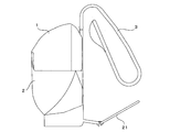
- FIG. 1 is a side view of a chemical solution supply apparatus according to the present embodiment
- FIG. 2 is a cross-sectional view with the chemical solution container removed in FIG. 1
- FIG. 3 is an exploded rear view of FIG. 1, and FIG. .
- This chemical solution supply device is used by being hung on a toilet rim.
- a chemical solution container 1 containing a chemical solution and an apparatus main body 2 for supporting the chemical solution container 1 from below.
- a suspension member 3 for hanging the device on the rim.
- a chemical liquid discharge mechanism 4 that supplies the chemical liquid flowing out from the chemical liquid container 1 to the bottom surface of the apparatus main body 2 is disposed inside the apparatus main body 2.
- the chemical solution discharging mechanism 4 is composed of an upper member and a lower member.
- the chemical solution container 1 is formed in a transparent dome shape and has a discharge port 11 on the lower surface.
- a cap 13 is attached to the discharge port 11.
- the cap 13 is composed of an annular main body portion and a thin film portion (not shown) that closes a hole in the center thereof. In use, the thin film portion is broken to discharge the chemical solution.
- the chemical solution stored in the chemical solution container 1 is for cleaning the aroma and the toilet bowl.
- the viscosity of the chemical solution stored in the chemical solution container 1 is not particularly limited. For example, it is 80 to 500 mPa ⁇ s at 25 ° C., or 200 to 2000 mPa ⁇ s at 5 ° C., preferably 120 to 300 mPa ⁇ s at 25 ° C.
- the viscosity here is set at a set temperature of 5 ° C. or 25 ° C. in a B type viscometer (manufactured by Toki Sangyo Co., Ltd .: model number TVB-10 type viscometer). 2. Measured under conditions of stirring conditions of 30 rpm and stirring time of 1 minute.
- the apparatus main body 2 includes a cup-shaped base 20 that supports the chemical solution container 1, and a support plate (support member) 21 that forms the bottom surface of the base 20 and extends toward the rim. It consists of The base 20 is formed in an elliptical shape in plan view, and is surrounded by a wall body 22 that surrounds the base 20. One side of the wall body 22 in the longitudinal direction is notched and opened, and the support plate 21 extends from the open portion 231.
- the support plate 21 includes a plate-like base portion 211 and a movable portion 212 that is swingably connected to one end portion thereof.
- a support column 24 extending upward is attached to the center of the base 20, and the suspension member 3 is attached to a space between the support column 24 and a cover member 411 described later so as to move up and down.
- the hanging member 3 is formed in a band shape that is bent at two locations so as to be elastically deformable. In an initial state, the hanging member 3 is folded as shown in FIG. Further, since the hanging member 3 is configured to be movable up and down, the height of the chemical solution container 1 and the apparatus main body 2 with respect to the rim can be adjusted so that the apparatus and the rim do not interfere with each other. As shown in FIG. 5, a trapezoidal through hole 201 is formed in the base 20.
- the through hole 201 is disposed in the vicinity immediately below the chemical solution outlet hole 428 in the chemical solution discharge mechanism 4 described later. Further, on the base 20, a pair of barrier walls 202 extending from the through hole 201 as a starting point and extending toward the movable portion 212 are formed. Both the shielding walls 202 extend so as to be separated from each other toward the movable portion 212 side. A shielding wall 203 is also formed on the side of the through hole 201 on the movable part 212 side. Thus, the three shielding walls 202 and 203 are arranged so as to partition the through hole 201 and the position immediately below the outflow hole 428.
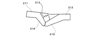
- FIG. 7 is an enlarged cross-sectional view of a connection portion between the base portion and the movable portion in the support plate.
- the base 211 and the movable portion 212 are integrally formed of resin or the like, and the base 211 is approximately moved toward the movable portion 212 side. Inclined downward at 6 degrees. Thereby, as will be described later, the chemical liquid discharged from the chemical liquid supply mechanism 4 can easily flow to the rim side.
- the inclination angle ⁇ of the base 211 can be set to other values, for example, can be 0 to 45 degrees, and is preferably 3 to 30 degrees.
- a groove 213 is formed on the back surface of the support plate 21 along the boundary line between the base portion 211 and the movable portion 212. Therefore, since the boundary between the base 211 and the movable portion 212 is formed into a thin film shape by the groove 213, the movable portion 212 can swing with respect to the base 211. Further, as shown in FIG. 7, protrusions 218 and 219 are formed on the lower surfaces of the base portion 211 and the movable portion 212 so as to face each other across the groove 213. Since such protrusions 218 and 219 are provided, when the movable portion 212 is inclined downward, the protrusions 218 and 219 sandwiching the groove 213 come into contact with each other, and thereby the downward inclination is restricted.
- the movable portion 212 is inclined upward at an inclination angle ⁇ of about 30 ° with respect to the base portion 211, and from this state, the base portion 211 is elastically deformed at the boundary portion. In contrast, tilting is possible in the range of about 0 to 90 °.
- the chemical solution discharging mechanism 4 is disposed between the chemical liquid container 1 and the support plate 21, and includes an upper member 41 disposed on the upper side and a lower member disposed on the lower side. 42.
- the upper member 41 is formed in an elliptical cylindrical shape in plan view, and the lower part is open.
- the lower member 42 includes a plate-like portion 421 having an elliptical shape in plan view, and a lower wall member 423 formed so as to extend in the vertical direction around the upper portion 41. It arrange
- medical solution is formed between both by combining the upper member 41 and the lower member 42 (refer FIG. 2).
- the upper member 41 and the lower member 42 will be described in more detail.
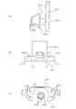
- FIG. 8 is a cross-sectional view (a), a front view (b), and a plan view (c) of the upper member.
- a rail-like cover member 411 extending upward is attached to the side surface of the upper member 41.
- the cover member 411 abuts on the support column 24 as described above, and the hanging member 3 Forming a space for housing
- the upper member 41 is provided with a sharp cylindrical communication pipe 412 with a sharply cut end at the center of the upper surface, and a total of four air outflow holes 413 at the end of the upper surface.
- the communication tube 412 is pierced by the cap 13 of the chemical solution container 1 described above and plays a role of breaking the thin film portion.
- a U-shaped groove 417 is formed on the periphery of the communication pipe 412, and the cap 13 is fitted into the groove 417.
- a cylindrical fixed pipe 414 extending toward the lower member 42 and three communication holes 415 arranged in the vicinity thereof are formed on the inner bottom surface of the communication pipe 412.
- the communication holes 415 and the air outflow holes 413 described above communicate with the buffer space 45.
- the opening area of the largest communication hole 415 among the plurality of communication holes 415 is preferably 0.6 to 1.8 mm 2 or more.
- FIG. 10 is a partial perspective view (a) of the lower member and a cross-sectional view taken along the line BB (b). )is there.
- a cylindrical guide tube 424 fitted to the fixed tube 414 of the upper member 41, and a circular fixed wall 425 provided so as to surround the periphery thereof. And are provided.
- the above-described fixed tube 414 is fitted into the gap between the guide tube 424 and the fixed wall 425.
- the upper opening of the guide tube 424 has an obliquely cut shape, and a V-shaped guide groove 426 extending in the vertical direction along the outer peripheral surface of the guide tube 424 from the lower side of the opening is formed.
- a chemical solution passage that is, a guide passage is formed by the inner wall surface of the fixed tube 414 and the guide groove 426. Is done.
- a space through which the chemical solution passes, that is, an extension path 427 is also formed in the gap between the bottom surface of the gap between the guide tube 424 and the fixed wall 425 and the lower end portion of the fixed tube 414.
- each extension path 427 is preferably 0.05 to 0.3 mm 3 , and more preferably 0.07 to 0.15 mm 3 .
- the cross-sectional area of the extension path 427 is preferably 0.02 to 0.1 mm 2 , and more preferably 0.03 to 0.05 mm 2 .
- the protrusion 43 is formed by a substrate 431 connecting both ends of the outflow hole 428 and a pair of extension portions 432 extending from both ends of the substrate 431. And each extension part 432 is extended in the diagonal direction to the movable part 212 side so that it may mutually space apart (refer FIG. 2).
- the length of the protrusion 43 can be 3 to 10 mm, for example, but the lower end of the protrusion 43 contacts the bottom surface of the apparatus body 2 as shown in FIG. It is preferable. Furthermore, as shown in FIG.
- the protrusion 43 has a plurality of grooves extending downward.
- the groove is formed in the protrusion 43 in this manner, the chemical liquid is easily held by the protrusion 43, and more chemical liquid can be smoothly supplied to the support plate 21 side.
- the depth of the groove can be 0.15 to 0.3 mm, and the width of the groove can be 0.4 to 0.8 mm.
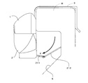
- FIG. 11 is a side view showing an attached state of the chemical solution supply apparatus.
- the chemical solution container 1 is disposed on the upper member 41.
- the communication pipe 412 is pierced into the cap 13 of the chemical solution container 1 and the chemical solution container 1 is fixed.
- the suspension member 3 is pushed out from the state of FIG. And as shown in FIG. 11, it arrange
- the movable portion 212 abuts on the inner wall surface of the toilet bowl, but can be swung with respect to the base portion 211, and therefore tilts according to the distance between the base portion 211 and the toilet inner wall surface S.
- the gap between the base 211 and the toilet inner wall surface S is filled.
- the flowed water travels along the toilet inner wall surface S from the inside of the rim R as shown in FIG. Guided to the 211 side (arrow X). And it flows into the toilet bowl while sweeping the medicinal solution stored at the boundary portion between the base portion 211 and the movable portion 212.
- the chemical solution is supplied to the toilet inner wall surface S together with running water, and the toilet bowl is cleaned.
- the water which flows on the support plate 21 may flow backward in the chemical solution discharge mechanism 4 and enter the chemical solution container 1, this is dealt with as follows. That is, in the apparatus according to the present embodiment, the chemical liquid flows out onto the support plate 21 via the guide groove 426 and the extension path 427.
- the extension path 427 extends horizontally, the water that has flowed upward through the protrusion 43 has to pass through the extension path 427 that extends horizontally and then pass through the guide groove 426 that extends further vertically. In this case, the chemical solution container 1 is not reached.
- route extended horizontally is arrange
- the through-hole 201 also plays the following role.
- the chemical liquid flows on the support plate 21 on the side opposite to the rim R, the chemical liquid is discharged from the through hole 201 to the outside of the apparatus. That is, since a chemical
- the chemical solution may solidify on the support plate 21.
- the through-hole 201 is formed in the bottom surface of the apparatus main body 2
- the chemical solution can be discharged to the outside through the through-hole 201, and the solidified on the support plate 21. Can be prevented.
- the shielding wall 203 is provided between the position directly below the outflow hole 428 and the through hole 201, only the chemical solution that has passed through the shielding wall 203 flows out of the through hole 201. This chemical solution remains on the support plate 21. Therefore, it can prevent that a chemical
- the chemical liquid discharged from the chemical liquid container 1 flows into the buffer space 45 and the guide groove 426 of the chemical liquid discharge mechanism 4.
- the inside of the chemical solution container 1 has a negative pressure, which makes it difficult to discharge the chemical solution.
- air or chemical liquid flows into the chemical liquid container 1 from the buffer space 45, so that the chemical liquid can be pushed out to the guide groove 426. Therefore, the chemical liquid can be smoothly discharged from the outflow hole 428.
- the temperature change may affect the air in the chemical container.
- the following effects are obtained.
- the air in the container 1 expands and the inside of the container 1 becomes positive pressure.
- the chemical solution in the chemical solution container 1 is pushed out and discharged.
- this chemical solution flows into the buffer space 45 through the communication hole 415 in addition to the guide groove 426, the chemical solution is excessive from the guide groove 426. It is prevented from flowing out.
- the temperature of the chemical liquid container 1 is lowered by being cooled by running water and the air in the chemical liquid container 1 is contracted to become negative pressure, the pressure of the air acts on the chemical liquid through the air outflow hole 413.
- the buffer space 45 is sucked into the chemical solution container 1 through the communication hole 415. As a result, it is possible to prevent the water that has flowed into the apparatus main body from being sucked into the chemical container and discharged. As described above, since the buffer space 45 circulates between the chemical solution container 1 and the buffer space 45 even when a pressure change occurs in the chemical solution container 1 due to a temperature change, It is possible to prevent the chemical solution from flowing out excessively or restricting outflow.
- the chemical solution supply device attached to the rim often does not contact the chemical solution container 1 with running water, and the chemical solution is discharged without being affected by the air pressure in the chemical solution container 1. Therefore, the discharge of the chemical solution can be caused by the movement of the air and the chemical solution between the chemical solution container 1 and the buffer space 45. Therefore, in particular, the opening area of each communication hole 415 that communicates both is preferably 0.6 to 1.8 mm 2 . For example, if the opening area of each communication hole 415 is larger than 1.8 mm 2 , the chemical solution and air easily flow from the buffer space 45 to the chemical solution container 1, and the chemical solution in the chemical solution container 1 may be excessively pushed out.
- the opening area of the communication hole 415 is smaller than 0.6 mm 2 , the amount of air or the chemical liquid flowing from the buffer space 45 to the chemical liquid container 1 becomes small, and the chemical liquid in the chemical liquid container 1 can be pushed out to the guide groove 426. become unable. Therefore, the chemical solution cannot be discharged smoothly.
- the support plate 21 does not necessarily have to be formed in a plate shape, as long as a surface for receiving a chemical solution is formed.
- the shape of the protrusion is not particularly limited as long as the chemical solution can be guided from the outflow hole 428 toward the support plate 21.
- the protrusion is formed in a rod shape or a plate shape having a short width. You can also.
- the communication hole 415 formed in the upper member 41 is set as follows.
- Example 1 Of the three communication holes 415 of FIG. 8C, the communication holes on both sides were filled into one.
- the diameter is 1.2 mm (opening area: 1.13 mm 2 ).
- Example 2 As in FIG. 8C, three communication holes having a diameter of 1.2 mm were formed (opening area of each communicating hole: 1.13 mm 2 , total opening area: 3.39 mm 2 ).
- Comparative Example 1 The three communication holes of Example 2 were connected to form one arc-shaped communication hole as shown in FIG. 12 (opening area: 8 mm 2 ).
- Comparative Example 2 Three communication holes having a diameter of 0.8 mm were formed as in FIG. 8C (opening area of each communication hole: 0.5 mm 2 , total opening area: 1.5 mm 2 ). The radial width of the guide groove 426 was 0.3 mm.
- an aromatic cleaning agent for flush toilets composed of a surfactant, a fragrance, and water was used as the chemical solution.
- This chemical solution had a viscosity of 240 mPa ⁇ s at 25 ° C. and 690 mPa ⁇ s at 5 ° C.
- the viscosity was set at a set temperature of 25 ° C. or 5 ° C. in a B-type viscometer (manufactured by Toki Sangyo Co., Ltd .: model number TVB-10 type viscometer). 2. Measurement was performed under the conditions of stirring at 30 rpm and stirring time of 1 minute.
- Comparative Example 1 when the opening area of the communication hole 415 is large, the air or the chemical liquid flowing into the chemical liquid container 1 from the buffer space 45 increases, and the outflow of the chemical liquid into the guide groove 426 is promoted. Therefore, it is considered that the weight loss of the chemical solution increases.
- Comparative Example 2 when the opening area of each communication hole 415 is small as in Comparative Example 2, the amount of air or chemical liquid flowing from the buffer space 45 into the chemical liquid container 1 decreases, and the chemical liquid in the chemical liquid container 1 can be pushed out. Disappear. Therefore, the chemical solution is not discharged. From Example 1 and Comparative Example 2, even when a plurality of communication holes are formed, the total opening area of the communication holes has a small effect, and the opening area of each communication hole is considered to have an effect.
Landscapes
- Health & Medical Sciences (AREA)
- Public Health (AREA)
- Epidemiology (AREA)
- Life Sciences & Earth Sciences (AREA)
- Engineering & Computer Science (AREA)
- Hydrology & Water Resources (AREA)
- Water Supply & Treatment (AREA)
- Bidet-Like Cleaning Device And Other Flush Toilet Accessories (AREA)
Abstract
【課題】温度変化によって、薬液が過度に排出されるのを防止することができる薬液供給装置を提供する。 【解決手段】本発明は、便器のリムに取り付けられる薬液供給装置であって、 所定の粘度を有する薬液を収容し、当該薬液の排出口を有する薬液容器と、排出口に接続され、薬液容器内の薬液を外部へと導く薬液排出機構と、薬液排出機構から排出された薬液を支持する支持部材と、薬液容器、薬剤排出機構、及び支持部材を便器のリムに吊り掛けるための吊掛部材と、を備え、薬液排出機構は、薬液容器から排出された薬液を収容する緩衝空間と、緩衝空間と外気とを連通させる少なくとも1つの空気流通孔と、薬液容器から排出された薬液を緩衝空間へ導く少なくとも1つの連通孔と、薬液容器から排出された薬液を支持部材側へ導く排出流路と、支持部材に向けて開口し、排出流路を経た薬液を排出する流出孔と、を備えている、
Description
本発明は、便器のリムに取り付けられ、便器を洗浄する薬液を供給する薬液供給装置に関する。
便器を洗浄したり、芳香効果を得るための薬液供給装置は、取付対象となる便器のタイプによって種々のものが提案されている。例えば、貯水タンクを有するタイプに対しては、タンク上部の手洗い部に配置される薬液供給装置が提案されており、この装置は、手洗い部に供給される水とともに、貯水タンク内に薬液を供給するように構成されている。
一方、タンク上部に手洗い部がないものや、貯水タンク自体を設けないタイプの便器も販売されており、これに対しては、便器のリムに直接取り付ける薬液供給装置が提案されている。例えば、特許文献1に記載の薬液供給装置は、便器のリムに吊り掛けられるように薬液ボトルを設け、その下方に薬液を受けるプレートを取り付けている。そして、薬液ボトルからプレート上に供給される薬液を流水によってさらうことで、便器の内壁面に薬液を供給している。これによって、便器が洗浄されるとともに、薬液に含まれる芳香成分により、芳香効果も得ることができる。
ところで、上記のような薬液供給装置は、便器のリムに取り付けられるものであるため、フラッシュ時の流水が装置に接触することは少ない。そのため、流水により装置が冷やされることが少なく装置自体の温度変化は少ないといえる。そのため、薬液の排出は、主として装置の機構に依存することになるが、上述した薬液排出装置では適切な排出量を実現するのが難しく、改善が要望されていた。
本発明は、上記問題を解決するためになされたものであり、便器のリムに取り付けられるタイプであって、適切な量の薬液の排出が可能な薬液供給装置を提供することを目的とする。
本発明は、便器のリムに取り付けられる薬液供給装置であって、所定の粘度を有する薬液を収容し、当該薬液の排出口を有する薬液容器と、前記排出口に接続され、前記薬液容器内の薬液を外部へと導く薬液排出機構と、前記薬液排出機構から排出された薬液を支持する支持部材と、前記薬液容器、薬剤排出機構、及び前記支持部材を便器のリムに吊り掛けるための吊掛部材と、を備え、前記薬液排出機構は、前記薬液容器から排出された薬液を収容する緩衝空間と、前記緩衝空間と外気とを連通させる少なくとも1つの空気流通孔と、前記薬液容器から排出された薬液を前記緩衝空間へ導く連通孔と、前記薬液容器から排出された薬液を前記支持部材側へ導く排出流路と、前記支持部材に向けて開口し、前記排出流路を経た薬液を排出する流出孔と、前記流出孔から排出される薬液が供給され、前記支持部材に向かって延びる板状の突出部とを備えている。
この構成によれば、薬液容器から排出された薬液は、薬液排出機構の緩衝空間と排出流路とへ流れる。排出流路を介して支持部材側へ薬液が排出されると、薬液容器内が負圧になるため、薬液が排出されにくくなる。これに対して、本発明においては、薬液容器に負圧が生じると、緩衝空間から空気または薬液が薬液容器内に流入するため、これによって薬液を排出流路へ押し出すことができる。したがって、薬液の排出をスムーズに行うことができる。
上記薬液供給装置において、連通孔を複数個形成した場合、複数の連通孔のうち、最も大きい連通孔の開口面積が0.6~1.8mm2であることが好ましい。また、連通孔を1個形成する場合には、その開口面積が、0.9~1.8mm2であることが好ましい。これは、次の理由からである。
まず、連通孔の開口面積が大きいと、薬液容器に流れ込む空気または薬液(特に空気)が多くなって、薬液容器から過度に薬液を押し出すことになり、薬液が早期になくなるおそれがある。この観点から、連通孔の開口面積は、1.8mm2以下であることが好ましい。連通孔が複数形成されている場合には、最も大きい連通孔が影響を与える可能性が高いため、最も大きい連通孔の開口面積が1.8mm2以下であることが好ましい。
一方、連通孔の開口面積が小さいと、緩衝空間から薬液容器へ流れる空気または薬液の量が小さくなり、薬液容器内の薬液を排出流路へ押し出すことができなくなる。そのため、薬液がスムーズに排出することができなくなる。したがって、複数の連通孔が形成されている場合には、最も大きい連通孔の開口面積は、0.6mm2以上であることが好ましい。但し、連通孔が1個の場合には、これよりも大きい0.9mm2以上であることが好ましい。これは、1個の連通孔で上述した連通孔の機能を確実に発揮させる必要があるためである。また、連通孔は非常に小さいため、成形時のばらつき等が発生した場合でも確実に上記機能を発揮させる必要があることによる。
上記連通孔の外周縁は、曲線により構成することができる。こうすることで、薬液及び空気がスムーズに通過しやすくなる。
また、流出孔から排出される薬液が供給され、支持部材に向かって延びる板状の突出部をさらに設けることができ、この突出部には、流出孔側から支持部材側に向かう複数の溝を形成することができる。なお、突出部は種々の構成をとることができるが、例えば、突出部を2つ以上設けたり、流出孔を中心に放射状に延びるように構成することができる。このように構成すれば、薬液をさらに広範囲に行き渡らせることができる。なお、ここでいう放射状とは、360°全ての向きに突出部が延びている必要はなく、その一部、特に、リム側を向く所定の角度に亘って突出部が配置されていればよい。
この構成によれば、流出孔から排出される薬液を支持部材へ案内し易くなり、薬液をスムーズに排出することができる。また、突出部に、流出孔から支持部材に向かう複数の溝を形成されているため、毛管現象により薬液の流れを助長することができ、粘度が高い薬液であってもよりスムーズに排出することができる。
上記薬液供給装置においては、支持部材が、薬液排出機構から排出された薬液を、便器内を流れる流水と接触可能に支持するように構成することができる。これにより、排出された薬液が流水に接触してさらわれるため、薬液を便器に行き渡らせることができる。
また、上記薬液供給装置においては、薬液容器が、フラッシュ時の流水の経路に配置されないような便器のリムに取り付けられるようにすることができる。
また、流出孔に、フラッシュ時の流水が到達しないような便器のリムに取り付けられるようにすることもできる。
支持部材には、便器を臨む少なくとも1つの貫通孔を形成することができる。こうすることで、流水によって薬液がさらわれない場合であっても、支持部材に供給された薬液が貫通孔を介して便器に排出することができる。
本発明に係る薬液供給装置によれば、適切な量の薬液の排出が可能な薬液供給装置を提供することを目的とする。
以下、本発明に係る薬液供給装置の一実施形態について図面を参照しつつ説明する。図1は本実施形態に係る薬液供給装置の側面図、図2は図1において薬液容器を取り外した断面図、図3は図1の分解背面図、図4は図1の分解側面図である。
この薬液供給装置は、便器のリムに吊り掛けて使用されるものであり、図1~図4に示すように、薬液が収容された薬液容器1と、これを下方から支持する装置本体2と、装置をリムに吊り掛けるための吊掛部材3とを有している。また、装置本体2の内部には、薬液容器1から流れ出た薬液を装置本体2の底面へと供給する薬液排出機構4が配置されている。この薬液排出機構4は、後述するように、上部材と下部材とで構成されている。以下、上述した各部材をさらに詳細に説明する。
図3に示すように、薬液容器1は、透明のドーム状に形成され、下面に排出口11を有している。そして、この排出口11には、キャップ13が取り付けられている。このキャップ13は、環状の本体部と、その中央の穴を塞ぐ薄膜部(図示省略)とで構成されており、使用に際しては、薄膜部を破断させて薬液を排出させる。薬液容器1に収容される薬液は、芳香及び便器の洗浄を行うためのものである。なお、薬液容器1に収納される薬液の粘度は、特には限定されないが、例えば、25℃において80~500mPa・s、または5℃において200~2000mPa・s、好ましくは、25℃において120~300mPa・s、または5℃において300~1200mPa・sとすることができる。ここでいう粘度は、B型粘度計(東機産業株式会社製:型番 TVB-10形粘度計)において、設定温度5℃または25℃で設定、ローターNo.2、攪拌条件30rpm、攪拌時間1分の条件において測定される。
図5は装置本体の平面図、図6は図5のA-A線断面図である。図5及び図6に示すように、装置本体2は、薬液容器1を支持するカップ状の基台20と、この基台20の底面を構成しリム側に延びる支持プレート(支持部材)21とで構成されている。基台20は、平面視楕円状に形成され、その周囲を囲む壁体22で囲まれている。壁体22のうち、長手方向の一辺は切り欠かれて開放されており、この開放部分231から支持プレート21が延びている。支持プレート21は、板状の基部211と、その一端部に揺動自在に連結された可動部212とで構成されている。
また、基台20の中央には、上方へ延びる支柱24が取り付けられており、この支柱24と後述するカバー部材411との間の空間に、吊掛部材3が上下動可能に取り付けられる。吊掛部材3は、弾性変形可能に2箇所で折り曲げられた帯状に形成されており、初期状態では、図1のように折り畳まれている。また、吊掛部材3は、上下動可能に構成されているため、装置とリムとが干渉しないように、リムに対する薬液容器1及び装置本体2の高さを調整することができる。また、図5に示すように、基台20には、台形状の貫通孔201が形成されている。貫通孔201は、後述する薬液排出機構4における薬液の流出孔428の直下の近傍に配置されている。また、基台20上には、貫通孔201を始点として、可動部212側に傾斜して延びる一対の遮壁202が形成されている。両遮壁202は、可動部212側に向かって互いに離れるように、裾広がりに延びている。また、貫通孔201の可動部212側の辺にも遮壁203が形成されている。これにより、3つの遮壁202,203が、貫通孔201と、流出孔428の直下の位置とを仕切るように配置されている。
次に、支持プレート21についてさらに詳細に説明する。図7は、支持プレートにおける基部と可動部との連結部分の拡大断面図である。図6及び図7に示すように、本実施形態の支持プレート21においては、基部211と可動部212とが樹脂などで一体的に形成されており、基部211が可動部212側に向かって約6度で下方に傾斜している。これにより、後述するように、薬液供給機構4から排出された薬液がリム側へ流れやすいようにしている。基部211の傾斜角度αは、これ以外に設定することも可能であり、例えば、0~45度にすることができ、3~30度であることが好ましい。
そして、支持プレート21の裏面には、基部211と可動部212との境界線に沿って溝213が形成されている。したがって、この溝213によって基部211と可動部212との境界が薄膜状になるため、可動部212が基部211に対して揺動可能となっている。また、図7に示すように、溝213を挟んで基部211と可動部212の下面には、それぞれ突部218,219が対向するように形成されている。このような突部218,219が設けられているため、可動部212を下方に傾斜させようとすると、溝213を挟む両突部218,219が当接し、これによって下方への傾斜が規制される。なお、初期状態では、図6に示すように、可動部212は基部211に対して、約30°の傾斜角度βで上方に傾斜しており、この状態から境界部分の弾性変形によって、基部211に対し約0~90°程度の範囲で傾斜が可能となっている。
続いて、薬液排出機構4について説明する。図2~図4に示すように、薬液排出機構4は、薬液容器1と支持プレート21との間に配置されており、上側に配置される上部材41と、下側に配置される下部材42とで構成されている。上部材41は、平面視楕円型の筒状に形成されており、下方が開放している。一方、図9に示すように下部材42は、平面視楕円状の板状部421と、その周囲に上下方向に延びるように形成された低い壁部材423とで構成されており、上部材41の下部開口を塞ぐように配置される。そして、上部材41と下部材42とが組み合わされることで、両者の間には、薬液を保持する緩衝空間45が形成される(図2参照)。以下、上部材41及び下部材42についてさらに詳細に説明する。
まず、上部材41について説明する。図8は上部材の断面図(a)、正面図(b)、及び平面図(c)である。同図に示すように、上部材41の側面には、上方に延びるレール状のカバー部材411が取り付けられており、このカバー部材411は、上述した通り、支柱24に当接し、吊掛部材3を収容する空間を形成する。また、上部材41の上面中央部には、先端が斜めに切りかかれて鋭利な円筒状の連通管412が設けられるとともに、上面の端部には合計4つの空気流出孔413が形成されている。連通管412は、上述した薬液容器1のキャップ13に突き刺され、薄膜部を破断させる役割を果たす。また、連通管412の周縁には、U字状の溝417が形成されており、この溝417にキャップ13が嵌るようになっている。一方、連通管412の内部底面には、下部材42側へ延びる円筒状の固定管414と、その近傍に配置された3個の連通孔415とが形成されている。そして、これら連通孔415と、上述した空気流出孔413とは、緩衝空間45と連通している。なお、連通孔415が複数個形成されている場合、複数の連通孔415のうち、最も大きい連通孔415の開口面積が0.6~1.8mm2以上とすることが好ましい。
続いて、下部材42について図9及び図10も合わせて説明する。図9は下部材の断面図(a)、正面図(b)、及び底面図(c)であり、図10は下部材の一部斜視図(a)及びそのB-B線断面図(b)ある。まず、図9に示すように、下部材42の中央には、上部材41の固定管414に嵌合する円筒状の案内管424と、その周囲を囲むように設けられた円形の固定壁425とが設けられている。そして、案内管424と固定壁425との間の隙間には、上述した固定管414が嵌るようになっている。案内管424の上部開口は、斜めに切り取られた形状となっており、その開口の低い側から案内管424の外周面に沿って上下方向に延びるV字状の案内溝426が形成されている。ここで、図9及び図10に示すように、案内管424は固定管414の内部に嵌っているため、固定管414の内壁面と、案内溝426とで薬液の通路、つまり案内路が形成される。また、案内管424と固定壁425との隙間の底面と固定管414の下端部との隙間にも薬液が通過する空間、つまり延長路427が形成される。より詳細に説明すると、上記隙間の底面においては、案内溝426の両側の各約90度が薬液の延長路427を構成するとともに、案内溝426とは反対側には、約180度に亘る半円形の流出孔428が形成されている。そして、延長路427を通過した薬液が流出孔428から支持プレート21側へ流れ出るようになっている。なお、各延長路427の容積は、0.05~0.3mm3であることが好ましく、0.07~0.15mm3であることがさらに好ましい。また、延長路427の断面積は、0.02~0.1mm2であることが好ましく、0.03~0.05mm2であることがさらに好ましい。
図9に示すように、下部材42の下面には、上述した流出孔428の両端をと接触する板状の突条部43が設けられている。より詳細には、この突条部43は、流出孔428の両端を結ぶ基板431と、この基板431の両端から延びる一対の延長部432とで形成されている。そして、各延長部432は、互いに離間するように、可動部212側へ斜め方向に延びている(図2参照)。また、突条部43の上下方向の長さは、例えば、3~10mmにすることができるが、図2に示すように、突条部43の下端部は、装置本体2の底面に接触していることが好ましい。さらに、図9に示すように、突条部43には、下向きに延びる複数の溝が形成されている。このように突条部43に溝を形成すると、薬液が突条部43に保持されやすくなり、より多くの薬液を支持プレート21側へスムーズに供給することができる。なお、溝の深さは、例えば、0.15~0.3mmにすることができ、溝の幅は0.4~0.8mmにすることができる。
次に、上記のように構成された薬液供給装置の使用方法について図11も参照しつつ説明する。図11は薬液供給装置の取り付け状態を示す側面図である。まず、薬液容器1を上部材41上に配置する。これにより、薬液容器1のキャップ13に連通管412が突き刺さり、薬液容器1が固定される。続いて、この装置を便器のリムに取り付ける際には、吊掛部材3を、支柱24から引き出して高さを調整しつつ、図1の状態からコ字状に押し広げる。そして、図11に示すように、リムRを挟むように配置する。このとき、可動部212は、便器の内壁面に当接するのであるが、基部211に対して揺動可能となっているため、基部211と便器内壁面Sとの距離に応じて、傾斜する。こうして、基部211と便器内壁面Sとの隙間は埋められる。その結果、基部211に流れ出た薬液を効率よくさらって、便器へ流すことができるため、便器の形状にかかわらず、優れた洗浄効果を得ることができる。
続いて、薬液の流れについて説明する。連通管412によりキャップ13の薄膜部が破断されると、薬液は、薬液容器1から薬液排出機構4へと流れ出て、一部は連通管412及び連通孔415を介して緩衝空間45内に流れ込む。一方、残りの薬液は、図10に示すように、案内溝426を通過して下方へ流れた後、延長路427及び流出孔428を介して下部材42の下面側に流れ出る。そして、この薬液は、突条部43を伝って下方へ移動し、支持プレート21上へ移る。また、薬液容器1から案内溝426へ薬液が排出されると、薬液の排出に伴って薬液容器1内は負圧になる。これに伴って、緩衝空間45内の薬液及び空気は、連通孔415を介して薬液容器1内へ流入していく。こうして、薬液や空気が薬液容器1内に流れ込むと、薬液容器1内の薬液が押し出され、案内溝426へと流出していく。
上記のように装置が設置された後、便器内に水が流されると、流された水は、図11に示すように、リムRの内側から便器内壁面Sを伝い、可動部212によって基部211側へ案内される(矢印X)。そして、基部211と可動部212との境界部分に貯まった薬液をさらいつつ、便器へと流れていく。こうして、薬液は流水とともに、便器内壁面Sに供給され、便器の清浄が行われる。なお、支持プレート21上に流れ込む水が薬液排出機構4を逆流して薬液容器1内に入り込むおそれもあるが、これについては次のように対処される。すなわち、本実施形態に係る装置では、薬液は、案内溝426及び延長路427を介して支持プレート21上に流れ出る。特に、延長路427は水平に延びているため、突条部43を介して上方に流れた水は、一旦水平に延びる延長路427を通過した後、さらに垂直に延びる案内溝426を通過しなければ、薬液容器1には到達しない。このように、この装置では、支持プレート21から薬液容器1に至る垂直方向の経路の中に水平に延びる経路を配置しているので、水の進入を防止することができる。
また、貫通孔201は、次のような役割も果たす。例えば、装置がリムに対して傾いて取り付けられた場合、薬液が支持プレート21上でリムRとは反対側に流れたとしても、この薬液は貫通孔201から装置外部へ排出される。つまり、薬液が便器に流れるため、流水に接触させることができる。したがって、所望の角度で装置をリムに対して取り付けられていない場合であっても、薬液を流水に接触させることができ、所望の芳香、洗浄効果を得ることができる。また、流水が装置本体2内に流入しない場合であっても、薬液を貫通孔201を介して便器に流出させることができる。
また、薬液が支持プレート21上に供給されても長時間流水がなければ、薬液が支持プレート21上で固まるおそれがある。この場合、上記のように、装置本体2の底面に貫通孔201が形成されていると、この貫通孔201を介して薬液を外部に排出することも可能となり、支持プレート21上で固まるのを防止することができる。
また流出孔428の直下の位置と貫通孔201との間に遮壁203を設けているため、遮壁203を越えた薬液のみが貫通孔201から流れ出すため、装置が傾いていたとしても、ある程度の薬液は支持プレート21上に残ることになる。よって、薬液が過度に貫通孔201から排出されるのを防止することができ、流水によって支持プレート21上の薬液がさらわれるようになる。
以上のように、本実施形態によれば、薬液容器1から排出された薬液は、薬液排出機構4の緩衝空間45と案内溝426とへ流れる。案内溝426を介して支持プレート21側へ薬液が排出されると、薬液容器1内が負圧になるため、薬液が排出されにくくなる。ここで、本実施形態においては、薬液容器1に負圧が生じると、緩衝空間45から空気または薬液が薬液容器1内に流入するため、これによって薬液を案内溝426へ押し出すことができる。したがって、薬液を流出孔428からスムーズに排出することができる。
このほか、温度変化が薬液容器内の空気に影響を与えることもあり、その場合、次のような効果がある。例えば、温度が上昇して薬液容器1が暖められた場合には、容器1内の空気が膨張し容器1内部は正圧になる。この場合、薬液容器1内の薬液は押し出されて排出されるが、この薬液は案内溝426のほか、連通孔415を介して緩衝空間45内にも流れ込むため、薬液が案内溝426から過剰に流出されるのが防止される。一方、流水によって冷やされるなどして薬液容器1の温度が低下し、薬液容器1内の空気が収縮して負圧になると、薬液は、空気流出孔413を介して空気の圧力が作用している緩衝空間45から連通孔415を介して薬液容器1内に吸い込まれる。その結果、装置本体側に流入してきた水の薬液容器への吸い上げや薬液の排出が制限されるのを防止することができる。このように、緩衝空間45は、温度変化によって薬液容器1内に圧力変化が生じた場合であっても、ほとんどの薬液が薬液容器1と緩衝空間45との間で流通するため、容器1内の薬液が過剰に流出したり、或いは流出が制限されるのを防止することができる。
但し、リムに取り付けられる薬液供給装置は、薬液容器1に流水が接触しないことが多く、薬液容器1内の空気圧の影響を受けず、薬液が排出される。そのため、薬液の排出は、薬液容器1と緩衝空間45との間の空気及び薬液の移動により生じ得る。そのために、特に、両者を連通する各連通孔415の開口面積は、0.6~1.8mm2とすることが好ましい。例えば、各連通孔415の開口面積が1.8mm2より大きいと、緩衝空間45から薬液容器1へ薬液及び空気が流れやすくなり、薬液容器1の薬液が過度に押し出される可能性がある。一方、連通孔415の開口面積が、0.6mm2より小さいと、緩衝空間45から薬液容器1へ流れる空気または薬液の量が小さくなり、薬液容器1内の薬液を案内溝426へ押し出すことができなくなる。そのため、薬液がスムーズに排出することができなくなる。
以上、本発明の実施形態について説明したが、本発明は上記各実施形態に限定されるものではなく、その趣旨を逸脱しない限りにおいて、種々の変更が可能である。例えば、支持プレート21は、必ずしもプレート状に形成していなくてもよく、薬液を受ける面が形成されていればよい。また、突条部の形態は、薬液を流出孔428から支持プレート21に向かって案内できる構造であれば、特には限定されず、例えば、棒状に形成したり、幅の短い板状に形成することもできる。
以下、本発明の実施例について説明する。但し、本発明はこの実施例に限定されるものではない。
ここでは、上述した連通孔の総開口面積の影響について検討する。上記実施形態において、上部材41に形成される連通孔415を次のように設定した。
実施例1:図8(c)の3つの連通孔415のうち、両側の連通孔を埋めて、1個にした。直径は1.2mmである(開口面積:1.13mm2)。
実施例2:図8(c)と同じく、直径1.2mmの連通孔を3個形成した(各連通孔の開口面積:1.13mm2、総開口面積:3.39mm2)。
比較例1:実施例2の3つの連通孔を接続し、図12に示すように、円弧状の1個の連通孔を形成した(開口面積:8mm2)。
比較例2:図8(c)と同じく、直径0.8mmの連通孔を3個形成した(各連通孔の開口面積:0.5mm2、総開口面積:1.5mm2)
また、案内溝426の径方向の幅は、0.3mmとした。
また、案内溝426の径方向の幅は、0.3mmとした。
以上のような薬液供給装置において、界面活性剤、香料、及び水からなる水洗トイレ用芳香洗浄剤を薬液として用いた。この薬液は、粘度が25℃において240mPa・s、5℃において690mPa・sのものを用いた。なお、粘度は、B型粘度計(東機産業株式会社製:型番 TVB-10形粘度計)において、設定温度25℃または5℃で、ローターNo.2、攪拌条件30rpm、攪拌時間1分の条件において測定した。そして、実施例及び比較例をそれぞれ2個ずつ自然放置し、3日間に薬液容器から排出された薬液の重量を測定した。その後、減少した薬液の量から薬液がすべて無くなるまでの日数を換算した。結果は、以下の通りである。

以上の結果によれば、比較例1のように、連通孔415の開口面積が大きいと、緩衝空間45から薬液容器1に流れ込む空気または薬液が多くなり、案内溝426への薬液の流出を助長するため、薬液の減量が大きくなると考えられる。一方、比較例2のように、各連通孔415の開口面積が小さい場合には、緩衝空間45から薬液容器1に流れ込む空気または薬液の量が少なくなり、薬液容器1の薬液を押し出すことができなくなる。よって、薬液が排出されなくなる。実施例1及び比較例2からすると、連通孔が複数形成されている場合であっても、連通孔の総開口面積は影響が小さく、各連通孔の開口面積が影響を与えると考えられる。
1 薬液容器
21 支持プレート
3 吊掛部材
4 薬液排出機構
426 案内溝(排出流路)
427 延長路(排出流路)
428 流出孔
43 突条部(突出部)
431 基板(突出部)
432 延長部(突出部)
45 緩衝空間
21 支持プレート
3 吊掛部材
4 薬液排出機構
426 案内溝(排出流路)
427 延長路(排出流路)
428 流出孔
43 突条部(突出部)
431 基板(突出部)
432 延長部(突出部)
45 緩衝空間
Claims (9)
- 便器のリムに取り付けられる薬液供給装置であって、
所定の粘度を有する薬液を収容し、当該薬液の排出口を有する薬液容器と、
前記排出口に接続され、前記薬液容器内の薬液を外部へと導く薬液排出機構と、
前記薬液排出機構から排出された薬液を支持する支持部材と、
前記薬液容器、薬剤排出機構、及び前記支持部材を便器のリムに吊り掛けるための吊掛部材と、を備え、
前記薬液排出機構は、
前記薬液容器から排出された薬液を収容する緩衝空間と、
前記緩衝空間と外気とを連通させる少なくとも1つの空気流通孔と、
前記薬液容器から排出された薬液を前記緩衝空間へ導く少なくとも1つの連通孔と、
前記薬液容器から排出された薬液を前記支持部材側へ導く排出流路と、
前記支持部材に向けて開口し、前記排出流路を経た薬液を排出する流出孔と、
を備えている、薬液供給装置。 - 前記連通孔が複数個形成されており、前記複数の連通孔のうち、最も大きい連通孔の開口面積が0.6~1.8mm2である、請求項1に記載の薬液供給装置。
- 前記連通孔が1個形成されており、その開口面積が、0.9~1.8mm2である、請求項1に記載の薬液供給装置。
- 前記連通孔の外周縁が、曲線により構成されている、請求項1から3のいずれかに記載の薬液供給装置。
- 前記流出孔から排出される薬液が供給され、前記支持部材に向かって延びる板状の突出部をさらに備え、
前記突出部には、前記流出孔側から前記支持部材側に向かう複数の溝が形成されている、請求項1から4のいずれかに記載の薬液供給装置。 - 前記支持部材は、前記薬液排出機構から排出された薬液を、便器内を流れる流水と接触可能に支持する、請求項1から5のいずれかに記載の薬液供給装置。
- 前記薬液容器が、フラッシュ時の流水の経路に配置されないように便器のリムに取り付けられる、請求項1から6のいずれかに記載の薬液供給装置。
- 前記流出孔に、フラッシュ時の流水が到達しないように、便器のリムに取り付けられる、請求項1から6のいずれかに記載の薬液供給装置。
- 前記支持部材には、便器を臨む少なくとも1つの貫通孔が形成されている、請求項1から8のいずれかに記載の薬液供給装置。
Applications Claiming Priority (4)
| Application Number | Priority Date | Filing Date | Title |
|---|---|---|---|
| JP2009067118 | 2009-03-18 | ||
| JP2009-067118 | 2009-03-18 | ||
| JP2009114390A JP5606010B2 (ja) | 2009-03-18 | 2009-05-11 | 薬液供給装置 |
| JP2009-114390 | 2009-05-11 |
Publications (1)
| Publication Number | Publication Date |
|---|---|
| WO2010107046A1 true WO2010107046A1 (ja) | 2010-09-23 |
Family
ID=42739706
Family Applications (1)
| Application Number | Title | Priority Date | Filing Date |
|---|---|---|---|
| PCT/JP2010/054507 Ceased WO2010107046A1 (ja) | 2009-03-18 | 2010-03-17 | 薬液供給装置 |
Country Status (2)
| Country | Link |
|---|---|
| JP (1) | JP5606010B2 (ja) |
| WO (1) | WO2010107046A1 (ja) |
Cited By (2)
| Publication number | Priority date | Publication date | Assignee | Title |
|---|---|---|---|---|
| WO2020115348A1 (es) * | 2018-12-04 | 2020-06-11 | Suavizantes Y Plastificantes Bituminosos, S.L. | Colgador dosificador para inodoro |
| CN115335576A (zh) * | 2020-03-31 | 2022-11-11 | 小林制药株式会社 | 药液供给装置 |
Citations (2)
| Publication number | Priority date | Publication date | Assignee | Title |
|---|---|---|---|---|
| JP2008163686A (ja) * | 2006-12-28 | 2008-07-17 | Kobayashi Pharmaceut Co Ltd | 通液構造及び該通液構造を備えた薬液供給装置 |
| WO2009028615A1 (ja) * | 2007-08-31 | 2009-03-05 | Kobayashi Pharmaceutical Co., Ltd. | 薬液供給装置 |
-
2009
- 2009-05-11 JP JP2009114390A patent/JP5606010B2/ja active Active
-
2010
- 2010-03-17 WO PCT/JP2010/054507 patent/WO2010107046A1/ja not_active Ceased
Patent Citations (2)
| Publication number | Priority date | Publication date | Assignee | Title |
|---|---|---|---|---|
| JP2008163686A (ja) * | 2006-12-28 | 2008-07-17 | Kobayashi Pharmaceut Co Ltd | 通液構造及び該通液構造を備えた薬液供給装置 |
| WO2009028615A1 (ja) * | 2007-08-31 | 2009-03-05 | Kobayashi Pharmaceutical Co., Ltd. | 薬液供給装置 |
Cited By (2)
| Publication number | Priority date | Publication date | Assignee | Title |
|---|---|---|---|---|
| WO2020115348A1 (es) * | 2018-12-04 | 2020-06-11 | Suavizantes Y Plastificantes Bituminosos, S.L. | Colgador dosificador para inodoro |
| CN115335576A (zh) * | 2020-03-31 | 2022-11-11 | 小林制药株式会社 | 药液供给装置 |
Also Published As
| Publication number | Publication date |
|---|---|
| JP5606010B2 (ja) | 2014-10-15 |
| JP2010242479A (ja) | 2010-10-28 |
Similar Documents
| Publication | Publication Date | Title |
|---|---|---|
| JP4145046B2 (ja) | 改良された液吐出便器クリーナ | |
| JP5606010B2 (ja) | 薬液供給装置 | |
| JP6736294B2 (ja) | 薬液供給装置 | |
| JP5213784B2 (ja) | 薬液供給装置 | |
| JP5506217B2 (ja) | 薬液供給装置 | |
| JP5334673B2 (ja) | 薬液供給装置 | |
| JP5578802B2 (ja) | 薬液供給装置 | |
| JP5164482B2 (ja) | 薬液供給装置 | |
| JP5424605B2 (ja) | 薬液供給装置 | |
| JP5578761B2 (ja) | 薬液供給装置 | |
| JP5478002B2 (ja) | 通液構造及び該通液構造を備えた薬液供給装置 | |
| JP5665279B2 (ja) | 薬液供給装置 | |
| JP5030712B2 (ja) | 薬液供給装置 | |
| JP5328125B2 (ja) | 薬剤供給装置 | |
| JP5601767B2 (ja) | 薬液供給装置 | |
| JP5448421B2 (ja) | 薬液供給装置 | |
| JP2009074350A (ja) | 薬液供給装置 | |
| JP5885448B2 (ja) | 薬液供給装置 | |
| JP4703252B2 (ja) | 薬液供給装置 | |
| JP5121536B2 (ja) | 薬液供給装置 | |
| JP2020105725A (ja) | 薬液供給装置 | |
| JP2004300665A (ja) | 薬液供給具 | |
| JP2020105723A (ja) | 薬液供給装置 | |
| JP2020105724A (ja) | 薬液供給装置 | |
| WO2020115348A1 (es) | Colgador dosificador para inodoro |
Legal Events
| Date | Code | Title | Description |
|---|---|---|---|
| 121 | Ep: the epo has been informed by wipo that ep was designated in this application |
Ref document number: 10753538 Country of ref document: EP Kind code of ref document: A1 |
|
| NENP | Non-entry into the national phase |
Ref country code: DE |
|
| 122 | Ep: pct application non-entry in european phase |
Ref document number: 10753538 Country of ref document: EP Kind code of ref document: A1 |