WO2010104135A1 - シミュレーション方法、システム及びプログラム - Google Patents
シミュレーション方法、システム及びプログラム Download PDFInfo
- Publication number
- WO2010104135A1 WO2010104135A1 PCT/JP2010/054056 JP2010054056W WO2010104135A1 WO 2010104135 A1 WO2010104135 A1 WO 2010104135A1 JP 2010054056 W JP2010054056 W JP 2010054056W WO 2010104135 A1 WO2010104135 A1 WO 2010104135A1
- Authority
- WO
- WIPO (PCT)
- Prior art keywords
- simulator
- simulation
- continuous
- discrete
- peripheral means
- Prior art date
Links
Images


Classifications
-
- G—PHYSICS
- G06—COMPUTING; CALCULATING OR COUNTING
- G06F—ELECTRIC DIGITAL DATA PROCESSING
- G06F30/00—Computer-aided design [CAD]
- G06F30/20—Design optimisation, verification or simulation
-
- G—PHYSICS
- G05—CONTROLLING; REGULATING
- G05B—CONTROL OR REGULATING SYSTEMS IN GENERAL; FUNCTIONAL ELEMENTS OF SUCH SYSTEMS; MONITORING OR TESTING ARRANGEMENTS FOR SUCH SYSTEMS OR ELEMENTS
- G05B17/00—Systems involving the use of models or simulators of said systems
- G05B17/02—Systems involving the use of models or simulators of said systems electric
-
- G—PHYSICS
- G06—COMPUTING; CALCULATING OR COUNTING
- G06F—ELECTRIC DIGITAL DATA PROCESSING
- G06F30/00—Computer-aided design [CAD]
- G06F30/10—Geometric CAD
- G06F30/15—Vehicle, aircraft or watercraft design
Definitions
- the present invention relates to a simulation of a physical system such as an automobile, and more particularly to a software-based simulation system.
- the ECU generally includes an input interface for A / D conversion, for example, an input interface from a sensor, a logical operation unit (microcomputer) that processes a digital input signal in accordance with a predetermined logic, and the processing result as an actuator. And an output interface for converting into an operation signal.
- a / D conversion for example, an input interface from a sensor
- microcomputer logical operation unit
- ABS Anti-lock Breaking System
- ESC Electronic Stability Control
- power steering wiper control and security monitoring system
- mechanical parts not only mechanical parts but also electronic parts and software account for an important proportion.
- the development cost for the latter is said to be 25% or 40% of the total, accounting for 70% for hybrid type vehicles.
- Electronic control is performed by arranging a plurality of ECUs.
- the ECUs are connected to each other via an in-vehicle network, for example, Controller Area Network (CAN).
- CAN Controller Area Network
- an engine, a transmission, or the like, which is a control target, is directly connected by a wire from each ECU.
- the ECU is a small computer that operates in response to an interrupt from a sensor input.
- an engine or the like continuously performs a mechanical operation. That is, a computer-based digital system and a mechanical-system physical system perform a cooperative operation in parallel in a single system called an automobile.
- the software that supports this is becoming increasingly complex, and there is a demand for the realization of a mechanism for not only verifying the operation of the ECU alone but also verifying a plurality of them simultaneously.
- the actuator driven by the output signal of the ECU includes an electromagnetic solenoid and a motor.
- Solenoids are used, for example, for engine injectors, transmission shift control, brake valve control, and door locks.
- HILS Hardware In-the-Loop Simulation
- a whole vehicle HILS Whole Vehicle Hardware In the Loop Simulation
- a real ECU is connected to a dedicated hardware device that emulates an engine, a transmission mechanism, and the like in a laboratory, and a test is performed according to a predetermined scenario.
- the output from the ECU is input to a monitoring computer and further displayed on a display, and a tester checks whether there is an abnormal operation while looking at the display.
- HILS requires a dedicated hardware device, and it must be physically wired between it and the real ECU, so preparation is difficult.
- the test after replacing with another ECU also takes time since it must be physically reconnected.
- real time is required for the test. Therefore, testing many scenarios takes a huge amount of time.
- a hardware device for HILS emulation is generally very expensive.
- SILS Software In the Loop Simulation
- the automobile simulation system has a continuous system simulator and a discrete system simulator.
- An example of a continuous system simulator is a simulator that simulates the mechanical part of an engine.
- an ECU simulator that operates at the timing of engine rotation pulses and controls the timing of fuel injection and ignition.
- a simulator that repeatedly calculates the operation of a car from torque distribution to each tire as an example of a continuous system simulator, and a periodic pulse signal every 10 milliseconds as an example of a discrete event system simulator.
- a simulator that simulates an ECU that operates on the vehicle and determines the torque distribution to each tire from the sensor input such as the yaw rate of the car.
- the discrete simulator reads and writes data through the I / O port in addition to the pulse signal input, asynchronously with the time slice of the continuous simulator. Typically, data from the sensor is read and updated.
- FIG. 1 shows a block diagram of a conventional typical discrete / continuous system simulation system.
- the discrete system simulator of this system includes ECU emulators 102, 104 and 106. In practice, it has a larger number of ECU emulators, but here only three are shown by way of example.
- the ECU emulator 102 includes a CPU emulator 102a and a peripheral emulator 102b.
- the CPU emulator 102a is a module that emulates the logic function of the original ECU.
- the peripheral emulator 102b receives a continuous pulse signal from the plant simulator 108 which is a continuous system simulator such as an engine simulator, converts it into an interrupt event signal, and passes it to the discrete CPU emulator 102a, or the CPU emulator 102a.
- the interrupt event signal received from is converted into a continuous pulse signal.
- each thread of the simulation program is enclosed by a dotted rectangular block.
- individual threads are assigned to individual cores or processors.
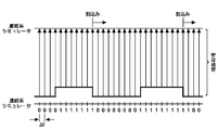
- FIG. 2 shows a timing chart of communication between the ECU emulators 102, 104 and 106 and the plant simulator 108.
- the ECU emulator as the discrete system and the plant simulator as the continuous system are synchronized with each clock.
- Japanese Patent Laid-Open No. 2001-290860 aims to provide a hardware / software co-simulator that seeks unnecessary synchronization processing between simulators with a simulator and reduces the synchronization processing, thereby improving the simulation speed.
- a simulation cooperation unit that synchronizes the CPU simulation unit and the peripheral circuit simulation unit, and a determination unit that determines whether or not to suppress synchronization in the simulation cooperation unit, and the simulation cooperation based on the determination unit It is disclosed to suppress synchronization in the means.
- Japanese Patent Laid-Open No. 8-227367 aims to obtain a debugger that increases the debugging speed using a high-speed simulator that ignores all system operations except system operations in which a design error is expected,
- a bus simulator for providing a signal corresponding to a bus cycle for interconnecting each simulator and means for omitting a bus cycle unnecessary for simulation, omitting a CPU bus cycle unrelated to simulation, or Disclosed is to generate only a clock signal schedule without explicitly simulating a periodic clock signal.
- Japanese Patent Application Laid-Open No. 2004-30228 includes a CPU simulator, one or more peripheral macro simulators, and a synchronous execution control processing unit that controls the synchronous execution of these peripheral macro simulators based on simulations by the CPU simulator.
- a simulation based on the terminal signal is executed, and the peripheral macro simulator detects the change of the input terminal signal and registers the changed terminal signal in the terminal signal list 22. , It is disclosed that the simulation is executed only for the registered terminal signal.
- Japanese Patent Application Laid-Open No. 2006-65758 discloses a circuit simulation technique in which a response function is given to a first discrete time model created from circuit data to generate a second discrete time model, and clock edge timing and a clock at this timing are generated. Disclosed is to calculate an effective signal value of a signal inputted to and outputted from a synchronous circuit using a second discrete model, and thereby to execute a simulation.
- the above-mentioned prior art aims to reduce the communication cost between simulators by a technique such as conditionally synchronizing the simulator or picking up the clock edge timing.
- the continuous system and the discrete system It does not sufficiently solve the problem of inter-thread communication or inter-processor communication.
- an object of the present invention is to reduce the communication cost between a continuous system and a discrete system in a simulation system.
- Another object of the present invention is to provide a simulation system in which a continuous system and a discrete system operate appropriately only by rough synchronization.
- the inventors of the present invention have repeated research and focused on the peripheral part of a discrete simulator such as an ECU emulator. That is, the ECU emulator includes a CPU emulator part and a peripheral part as shown in FIG. I thought there was a bottleneck in communication costs.
- the present inventor has come up with the idea that at least a part of the peripheral of the ECU emulator is operated in the same thread as the thread of the continuous system. With such a configuration, a continuous system and a part of the peripheral operate in the same thread, so the communication cost is low there.
- the continuous system and the discrete system operate appropriately only by taking coarse synchronization. That is, according to the first embodiment of the present invention, the discrete system operates independently regardless of the clock of the continuous system.
- the discrete system can access the clock module of the continuous system, and accesses the clock module only when the time is required, so that it is hardly a burden in terms of communication cost.
- the discrete system clock is synchronized with a clock (eg, 1/1000) thinned out of the clocks of the continuous system. • Access to the module is accessible.
- the second embodiment is employed when a software timer (time calculation) is used in a discrete system.
- the operation of the software timer is ensured by synchronizing with a period smaller than the minimum granularity of the timer.
- the peripherals of the discrete system is incorporated in the continuous system side so that the peripheral system operates on the same thread as that of the continuous system.
- the frequency of intercommunication is greatly reduced.
- the operating speed of the simulation system can be significantly improved by greatly reducing the cost of inter-thread communication.
- FIG. 2 is a block diagram of computer hardware used to implement the present invention. It is a figure which shows the functional block diagram of the simulation system which concerns on the Example of this invention. It is a figure which shows the timing chart of the simulation system of FIG. It is a figure which shows the more detailed functional block diagram of the simulation system which concerns on the Example of this invention.
- the ECU generally includes an input interface for A / D conversion, for example, an input interface from a sensor, a logical operation unit (microcomputer) that processes a digital input signal in accordance with a predetermined logic, and the processing result as an actuator. And an output interface for converting into an operation signal.
- a / D conversion for example, an input interface from a sensor
- a logical operation unit microcomputer
- an output interface for converting into an operation signal.
- the present invention will be described below in connection with an ECU of an automobile. However, the present invention is not limited thereto, and it should be understood that the present invention can be applied to general mechatronic mechanisms having other ECUs such as an aircraft and a robot. .
- the ECU detects the surrounding and environmental conditions, the state of the driving mechanism such as the engine, and the content of the instruction operation by a human by a sensor and inputs it as a signal. Specifically, signals from a water temperature sensor, intake air temperature sensor, boost pressure sensor, pump angle sensor, crank angle sensor, vehicle speed sensor, accelerator position sensor, A / T shift position, starter switch, air conditioner ECU, etc. is there.
- the ECU inputs these signals and outputs signals for driving electromagnetic spill valves, fuel cut solenoids, timing control valves, intake throttle VSV, glow plug relays, tachometers, air conditioner relays, etc. To do.
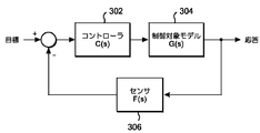
- FIG. 3 is a diagram showing an example of a feedback closed loop system, which is a typical control of the ECU. That is, in FIG. 3, a target signal is input to a controller 302 that is an ECU, and the ECU internally processes the target signal to output a drive signal, which is a model to be controlled, such as a plant such as an engine. The output of the plant 304 is fed back to the input of the controller 102 via the sensor 306.
- the target signal given here is, for example, throttle opening, idle control, brake force, shift, starter ON / OFF, battery voltage, injection energization time, number of times of injection energization, deposit, dwell angle, advance value,
- the parameters are an intake completion flag, ignition completion flag, atmospheric pressure, vehicle weight, rolling resistance coefficient, road gradient, adhesion coefficient, intake air temperature, and the like.
- feedback as a sensor signal includes throttle opening, intake pressure, intake air amount, shift, engine speed, vehicle speed, exhaust temperature, O 2 , cooling water temperature, air-fuel ratio, knock, ignition abnormality, etc. .
- the object controlled by the ECU may be a mechanical system solved by Newton's dynamic equation, an electric drive circuit solved by a response equation of an electric circuit, or a combination thereof. These are basically differential equations and can be described by being converted into a response function by Laplace transform according to control engineering.
- FIG. 4 is an example of such a response function description. 4 corresponds to the controller 302 in FIG. 3, the portion surrounded by the broken line 404 corresponds to the control target model 304 in FIG. 3, and the sensor 306 corresponds to the block 406. Note that FIG. 4 is an example of expression by a response function, and it should be understood that the present invention is not particularly limited.
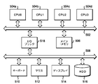
- the host bus 502 is connected with a plurality of CPU0 504a, CPU1 504b, CPU2 504c, and CPU3 504d. Further connected to the host bus 502 is a main memory 506 for arithmetic processing of the CPU 0 504a, CPU 1 504b, CPU 2 504c, and CPU 3 504d.
- a keyboard 510, a mouse 512, a display 514, and a hard disk drive 516 are connected to the I / O bus 508.
- the I / O bus 508 is connected to the host bus 502 via the I / O bridge 518.
- the keyboard 510 and the mouse 512 are used by an operator to enter commands or click menus to perform operations.
- the display 514 is used to display a menu for operating a program according to the present invention, which will be described later, using a GUI as necessary.
- CPU0 504a, CPU1 504b, CPU2 504c, CPU3 504d are, for example, Intel® Core 2 DUO, and the operating system is Windows (trademark) Server 2003.
- the operating system is stored in the hard disk drive 516 and is read from the hard disk drive 516 into the main memory 506 when the computer system is started.
- the number of CPUs shown here is four, but the number of CPUs is not limited to this, and may be a single processor system, or an arbitrary number of multicore or multiprocessor systems. Good.
- the hardware of the computer system that can be used for carrying out the present invention is not limited to IBM (R) System X, and any hardware can be used as long as it can run the simulation program of the present invention.
- a computer system can be used.
- the operating system is not limited to Windows (R), and any operating system such as Linux (R) or Mac OS (R) can be used.
- a computer system such as IBM (R) System P, which is based on POWER (trademark) 6 and operating system is AIX (trademark). May be used.
- the hard disk drive 516 further stores a plurality of logical processes such as an ECU emulator and a plant simulator, and a program for operating the plurality of logical processes in cooperation with each other, and can be activated by a keyboard 510 and a mouse 512. It is.
- emulator programs for all ECUs used in one vehicle are stored in the hard disk drive 516.
- the hard disk drive 516 further includes a scheduler for an ECU emulator program to be described later, a plant simulator program such as an engine, transmission, steering, and wiper, and a global time for managing the time of the entire system.
- a manager and a scenario generator program that stores various test scenarios such as climbing slopes, highways, and zigzag roads are also stored.
- emulator and “simulator” are used properly here, but the ECU code originally written on the assumption that it runs on another processor is targeted for CPU0 to CPU3, etc. Making it run is called emulation, and the program that does it is called an emulator. On the other hand, a system that virtually calculates the operation of a physical system such as an engine is called a simulator.
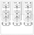
- the discrete system simulator of this system includes ECU emulators 602, 604, and 606. In practice, it has a larger number of ECU emulators, but here only three are shown by way of example.
- the program module of the system shown in FIG. 6 is stored in the hard disk drive 516 and is loaded from the hard disk drive 516 to the main memory 506 and operates by the operation of the operating system when the simulation system is started.
- the ECU emulator 602 includes a CPU emulator 602a and a hybrid peripheral 602b.
- the bridges 608, 610, and 612 are logic blocks that execute the function of the data input / output portion in a plant simulator such as an engine simulator.
- the hybrid peripherals 602b, 604b, and 606b, Communication is performed at every clock interval ⁇ t of the simulator.
- the dotted rectangular blocks indicate individual threads of the simulation program.
- individual threads are assigned to individual cores or processors.
- the hybrid peripherals 602b, 604b and 606b are functionally connected to the CPU emulators 602a, 604a and 606a, and bridges 608, 610 and 612, respectively, for the ECU emulators 602, 604 and 606.
- it plays a role of interfacing with each other, in a modular manner, it operates across the thread in which the plant simulator in which the bridges 608, 610 and 612 exist and the thread in which the ECU emulators 602, 604 and 606 operate. Be controlled.
- the name “hybrid” of the hybrid peripheral is derived from such a mixed existence. That is, a part of the hybrid peripheral is in the same thread as the ECU emulators 602, 604, and 606, and another part of the hybrid peripheral is in the same thread as the plant simulator.
- the hybrid peripherals 602b, 604b and 606b have shared memories 602c, 604c and 606c for reading and writing data, respectively. These memories 602c, 604c and 606c are preferably part of the main memory 506. Data can be read from and written to the memory by the component block of the hybrid peripheral and the ECU emulator.
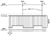
- FIG. 7 is a diagram showing an outline of a timing chart of the simulation system shown in the functional block diagram of FIG.
- a continuous simulator such as a plant simulator and a hybrid peripheral
- the communication is dense.
- part of the plant simulator and the hybrid peripheral are in the same thread, so inter-thread communication is not caused between them, and excessive communication costs are not caused.
- communication between the hybrid peripheral and the ECU emulator which is a discrete system simulator, occurs only at the timing when an interrupt occurs in the discrete system simulator or at a scheduled sparse timing.
- Communication from the hybrid peripheral to the ECU emulator is performed by sending an event signal.
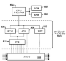
- FIG. 8 shows a more detailed functional block diagram of the functional block diagram.
- the ECU emulator 602 and the bridge 608 are shown here, but it should be understood that the ECU emulators 604 and 606 and the bridges 610 and 612 are the same.
- a ROM 802 and a RAM 804 are connected to the CPU emulator 602a. Since the simulation system described here is basically SILS, all functional blocks are realized by software modules. Thus, the ROM 802 is simply a collection of constant declarations, and the RAM 804 is a memory partition assigned to the main memory 506.
- the operation of the CPU emulator 602a may be executed by executing a binary obtained by reassembling the code obtained by disassembling the binary of the original emulator program, or executing the binary instruction of the emulator program while sequentially converting the binary instructions of the emulator program. But you can.
- the hybrid peripheral 602b includes an interrupt controller (INT-C) 806, an advanced timer unit (ATU) 808, a pin function controller (PFC) 810, and a watch dog timer. (WDT) 812.
- INT-C interrupt controller
- ATU advanced timer unit
- PFC pin function controller
- WDT watch dog timer.
- the configuration including the INT-C 806, the ATU 808, the PFC 810, and the WDT 812 is an example of the configuration of the hybrid peripheral 602b and is not limited thereto.
- the bridge 608 converts the input signal to the bridge 608 into a value provided to a pin of the PFC 810 by a variable mapping function.
- NE_PULSE is a pulse representing the rotation of the engine, and is generated 24 times per one rotation of the crankshaft in an example of an actual vehicle.
- A_F is air fuel consumption, which is the ratio of the amount of air entering the cylinder to the fuel. It should be understood that these are given by way of example only and that there are actually many other signals.
- the PFC 810 has a function of multiplexing data given as a variable corresponding to a pin from the bridge 608 by a variable mapping function and providing the multiplexed data to the INT-C 806 or the ATU 808.
- the INT-C 806 sends an event to the CPU emulator 602a in response to a change in the value or state given to the PFC 810 for each clock.
- the event includes a parameter value provided from the PFC 810.
- the ATU 808 is updated with the signal from the bridge.
- the CPU emulator 602a sets the start timing and duration in the ATU 808 based on the calculation result.
- the ATU 808 generates a pulse based on the received start timing and duration, and sends it to the continuous system according to the time slice. Examples of such calculation include the start timing and duration of fuel injection.
- the WDT 812 is a timer that constantly counts up and clears the count value in response to a signal from the CPU emulator 602a, and the count value exceeds a threshold value when no signal is received from the CPU emulator 602a for a certain period of time. Thus, a signal indicating that the operation of the CPU emulator 602a is not normal is output.
- FIG. 9 is a process flowchart showing the operations of the hybrid peripheral 602b and the CPU emulator 602a. It should be understood that the operations of the hybrid peripheral 604b and the CPU emulator 604a are substantially the same. Here, the hybrid peripheral 602b and the CPU emulator 602a will be described representatively.
- This process is called for each time slice ⁇ t.
- This process can be said to be an asynchronous process in the sense that the discrete system simulator is not synchronized with the pulse of the continuous system simulator.
- step 902 and step 908 processing specific to the configuration block is performed in the order of the configuration blocks of the ordered peripherals.
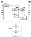
- the constituent blocks here are INT-C 806, ATU 808, PFC 810, and WDT 812, and this predetermined order is determined according to an order list 1002 as shown in FIG.
- This list is preferably placed at a predetermined location in the main memory 506.
- This list indicates the order of PFC ⁇ ATU ⁇ WDT ⁇ INT-C.
- FIG. 10 also shows that processing should be performed in the order of this list from continuous input to output.
- step 902 the process of reading data as the output of the CPU emulator 602a from the shared memory 602c of the hybrid peripheral 602b in step 904, and the input of the CPU emulator 602a to the shared memory 602c of the hybrid peripheral 602b in step 906 As a result, the data is overwritten and written.
- the CPU emulator 602a executes up to access to the I / O in step 910, and in step 912 performs I / O access to the shared memory 602c of the hybrid peripheral 602b. At this time, during the access to the shared memory 602c, exclusive control is performed so that other processing blocks do not rewrite the value of the shared memory 602c.
- FIG. 11 is a diagram showing a flowchart of the processing of the INT-C 806 of the hybrid peripheral 602b. This is a process unique to the INT-C 806 in the processing step 910 unique to the peripheral component block in FIG.
- INT-C takes input data from the PFC 810.
- INT-C determines whether to convert the input data into an interrupt. This determination is made, for example, by holding a previous value of a certain value and determining whether the value has changed from the previous time. Typically, it is the detection of the falling edge of a pulse.
- the INT-C sends an interrupt event message to the CPU emulator in step 1106, and the process ends.
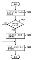
- FIG. 12 is a diagram showing an ATU808 flowchart of the hybrid peripheral 602b. This is processing unique to the ATU 808 in the processing step 910 specific to the peripheral component block in FIG. In FIG. 12, in step 1202, the ATU fetches input data from the PFC.
- step 1204 the ATU determines whether the timer is hit, that is, whether the timer value has reached a predetermined value. If so, at step 1206, the ATU changes the status of the output. Otherwise, go directly to step 1208.
- step 1208 the ATU writes the output data to the PFC, and the process ends.
- the start time and period can be set in the ATU 808 from the CPU emulator 602a, and the timer hit in step 1204 means that the start time is within the period.
- the function of the ATU 808 is, for example, to output a logic 1 through the PFC during the period from the start time, and to output a logic 0 otherwise.
- FIG. 13 is a diagram showing a flowchart of processing of another embodiment relating to processing operation between the peripheral and the ECU emulator. Unlike the processing of FIG. 9, in this embodiment, synchronization processing is performed for each designated cycle. The process of the flowchart of FIG. 13 is also called for each time slice ⁇ t.
- This embodiment is employed when a software timer (time calculation) is used in a discrete system. Here, the operation of the software timer is ensured by synchronizing with a period smaller than the minimum granularity of the timer.
- steps 1302 and 1308 the processing specific to the configuration block is performed in the order of the configuration blocks of the ordered peripherals.
- the constituent blocks here are INT-C 806, ATU 808, PFC 810, and WDT 812 in the example of FIG. 8, and this predetermined order is determined according to an order list 1002 as shown in FIG.
- This list is preferably placed at a predetermined location in the main memory 506.
- This list indicates the order of PFC ⁇ ATU ⁇ WDT ⁇ INT-C.
- FIG. 10 also shows that processing should be performed in the order of this list from continuous input to output.
- step 1302 the process of reading data as the output of the CPU emulator 602a from the shared memory 602c of the hybrid peripheral 602b in step 1304 and the input of the CPU emulator 602a to the shared memory 602c of the hybrid peripheral 602b in step 1306 As a result, the data is overwritten and written.
- t represents the current time in the continuous simulator
- ⁇ t represents the time slice size
- T represents the synchronization time of the CPU emulator.
- the CPU emulator 602a executes up to access to the I / O in step 1316, and in step 1318 performs I / O access to the shared memory 602c of the hybrid peripheral 602b. At this time, during the access to the shared memory 602c, exclusive control is performed so that other processing blocks do not rewrite the value of the shared memory 602c.
- step 1320 it is determined whether or not the designated cycle is finished. If not, the process returns to step 1316.
- step 1322 the CPU emulator 602a notifies the hybrid peripheral 602b that it has been completed. This notification is a notification from the CPU emulator 602a in step 1312.
- step 1324 the CPU emulator 602a waits for designation of the next cycle. Waiting here is a notification from step 1314. Processing then returns to step 1316.
- the peripheral part of the ECU emulator and the continuous system are in the same thread.
- the unit is not limited to a thread and can be assigned to a single processor or core. It may be a broader unit of process.
Abstract
Description
602b、604b、606b・・・ハイブリッド・ペリフェラル
switch (link_type) {
case NE_PULSE:
data.pi0 = link_value;
break;
case A_F:
data.pe23 = link_value;
break;
...
}
Claims (19)
- コンピュータの処理により、シミュレーションを行なうシミュレーション・システムにおいて、
連続パルスによって動作する連続系シミュレータと、
離散イベント・メッセージにより動作する離散系シミュレータと、
前記連続系シミュレータからの連続パルス信号を、イベント・メッセージに変換して前記離散系シミュレータに送出するするためのペリフェラル手段とを有し、
前記連続系シミュレータと前記ペリフェラル手段の少なくとも一部は、同一プロセスまたは同一スレッド内で動作するように制御される、
シミュレーション・システム。 - 前記ペリフェラル手段は、離散系シミュレータからのイベント・メッセージ信号を連続クロックの信号に変換して前記連続系シミュレータに送出する機能をさらに有する、請求項1のシミュレーション・システム。
- 前記離散系シミュレータのイベントが、割込みである、請求項1のシミュレーション・システム。
- 前記ペリフェラル手段と、離散系シミュレータは、非同期で通信する、請求項1のシミュレーション・システム。
- 前記ペリフェラル手段が、データを読み書き可能なメモリを有し、前記ペリフェラル手段と、離散系シミュレータは、該メモリへの読み書きによりデータを交換する、請求項4のシミュレーション・システム。
- 前記ペリフェラル手段が、前記連続クロック信号の周期よりも長い指定サイクル毎の同期で通信する、請求項1のシミュレーション・システム。
- 前記シミュレーション・システムが自動車のシミュレーション・システムであり、前記連続系シミュレータがエンジン・シミュレータを含み、前記離散系シミュレータが、該エンジン・シミュレータを制御するためのECUエミュレータを含む、請求項1のシミュレーション・システム。
- コンピュータの処理により、シミュレーションを行なうシミュレーション方法において、
連続パルスによって動作する連続系シミュレータを動作させるステップと、
離散イベント・メッセージにより動作する離散系シミュレータを動作させるステップと、
前記連続系シミュレータからの連続パルス信号を、イベント・メッセージに変換して前記離散系シミュレータに送出するするためのペリフェラル手段を動作させるステップを有し、
前記連続系シミュレータと前記ペリフェラル手段は、同一プロセスまたは同一スレッド内で動作するように制御される、
シミュレーション方法。 - 前記ペリフェラル手段は、離散系シミュレータからのイベント・メッセージ信号を連続クロックの信号に変換して前記連続系シミュレータに送出する機能をさらに有する、請求項8のシミュレーション方法。
- 前記離散系シミュレータのイベントが、割込みである、請求項8のシミュレーション方法。
- 前記ペリフェラル手段と、離散系シミュレータは、非同期で通信する、請求項8のシミュレーション方法。
- 前記ペリフェラル手段が、前記連続クロック信号の周期よりも長い指定サイクル毎の同期で通信する、請求項8のシミュレーション方法。
- 前記シミュレーション方法が自動車のシミュレーション方法であり、前記連続系シミュレータがエンジン・シミュレータを含み、前記離散系シミュレータが、該エンジン・シミュレータを制御するためのECUエミュレータを含む、請求項8のシミュレーション方法。
- コンピュータの処理により、シミュレーションを行なうシミュレーション・プログラムであって、
前記コンピュータをして、
連続パルスによって動作する連続系シミュレータを動作させるステップと、
離散イベント・メッセージにより動作する離散系シミュレータを動作させるステップと、
前記連続系シミュレータからの連続パルス信号を、イベント・メッセージに変換して前記離散系シミュレータに送出するするためのペリフェラル手段を動作させるステップを実行させる、
前記連続系シミュレータと前記ペリフェラル手段は、同一プロセスまたは同一スレッド内で動作するように制御される、
シミュレーション・プログラム。 - 前記ペリフェラル手段は、離散系シミュレータからのイベント・メッセージ信号を連続クロックの信号に変換して前記連続系シミュレータに送出する機能をさらに有する、請求項14のシミュレーション・プログラム。
- 前記ペリフェラル手段と、離散系シミュレータは、非同期で通信する、請求項14のシミュレーション・プログラム。
- 前記離散系シミュレータのイベントが、割込みである、請求項14のシミュレーション・プログラム。
- 前記ペリフェラル手段が、前記連続クロック信号の周期よりも長い指定サイクル毎の同期で通信する、請求項14のシミュレーション・プログラム。
- 前記シミュレーション・プログラムが自動車のシミュレーション・プログラムであり、前記連続系シミュレータがエンジン・シミュレータを含み、前記離散系シミュレータが、該エンジン・シミュレータを制御するためのECUエミュレータを含む、請求項14のシミュレーション・プログラム。
Priority Applications (4)
| Application Number | Priority Date | Filing Date | Title |
|---|---|---|---|
| US13/255,938 US8670967B2 (en) | 2009-03-12 | 2010-03-10 | Simulation method, system and article of manufacture |
| CN201080010432.0A CN102341787B (zh) | 2009-03-12 | 2010-03-10 | 模拟方法、系统 |
| EP10750888.9A EP2407886A4 (en) | 2009-03-12 | 2010-03-10 | SIMULATION PROCESS, SYSTEM AND PROGRAM |
| JP2011503850A JP5295355B2 (ja) | 2009-03-12 | 2010-03-10 | シミュレーション方法、システム及びプログラム |
Applications Claiming Priority (2)
| Application Number | Priority Date | Filing Date | Title |
|---|---|---|---|
| JP2009059790 | 2009-03-12 | ||
| JP2009-059790 | 2009-03-12 |
Publications (1)
| Publication Number | Publication Date |
|---|---|
| WO2010104135A1 true WO2010104135A1 (ja) | 2010-09-16 |
Family
ID=42728423
Family Applications (1)
| Application Number | Title | Priority Date | Filing Date |
|---|---|---|---|
| PCT/JP2010/054056 WO2010104135A1 (ja) | 2009-03-12 | 2010-03-10 | シミュレーション方法、システム及びプログラム |
Country Status (5)
| Country | Link |
|---|---|
| US (1) | US8670967B2 (ja) |
| EP (1) | EP2407886A4 (ja) |
| JP (1) | JP5295355B2 (ja) |
| CN (1) | CN102341787B (ja) |
| WO (1) | WO2010104135A1 (ja) |
Families Citing this family (10)
| Publication number | Priority date | Publication date | Assignee | Title |
|---|---|---|---|---|
| DE102011105141A1 (de) * | 2011-06-09 | 2012-12-13 | Dmg Electronics Gmbh | Verfahren und system zur simulation eines arbeitsprozesses an einer werkzeugmaschine |
| JP2013084163A (ja) * | 2011-10-12 | 2013-05-09 | Hitachi Ltd | 協調シミュレーション装置及び協調シミュレーション方法 |
| US9251308B2 (en) * | 2012-07-23 | 2016-02-02 | International Business Machines Corporation | Simulation method, system, and program |
| US9442716B2 (en) * | 2013-09-24 | 2016-09-13 | GM Global Technology Operations LLC | Methods and apparatus for adjusting a variable rate of requesting software data from a vehicle |
| JP6462329B2 (ja) * | 2014-11-19 | 2019-01-30 | 日立オートモティブシステムズ株式会社 | 故障シミュレーションシステム |
| JP6831193B2 (ja) * | 2016-08-26 | 2021-02-17 | トヨタ自動車株式会社 | ハイブリッド車両の制御装置 |
| US20180189896A1 (en) * | 2016-12-30 | 2018-07-05 | Paccar Inc | Systems and methods for improving electronic component quality during the manufacture of vehicles |
| US10652256B2 (en) * | 2017-06-20 | 2020-05-12 | International Business Machines Corporation | Real-time active threat validation mechanism for vehicle computer systems |
| JP6770935B2 (ja) * | 2017-07-03 | 2020-10-21 | 日立オートモティブシステムズ株式会社 | 車両制御装置用の検証装置 |
| WO2019214802A1 (en) * | 2018-05-07 | 2019-11-14 | Siemens Industry Software Nv | Method for simulating the operation of an electronic control unit |
Citations (6)
| Publication number | Priority date | Publication date | Assignee | Title |
|---|---|---|---|---|
| JPH08227367A (ja) | 1994-10-25 | 1996-09-03 | Mitsubishi Electric Res Lab Inc | ハードウエア−ソフトウエアデバッガ |
| JP2001290860A (ja) | 2000-04-10 | 2001-10-19 | Matsushita Electric Ind Co Ltd | ハードウエア/ソフトウエア協調シミュレータ |
| JP2003228496A (ja) * | 2002-02-05 | 2003-08-15 | Fujitsu Ltd | 制御プログラム開発支援装置 |
| JP2004030228A (ja) | 2002-06-26 | 2004-01-29 | Nec Electronics Corp | Lsiシミュレータ及びシミュレーション方法 |
| JP2006065758A (ja) | 2004-08-30 | 2006-03-09 | Fujitsu Ltd | 回路解析方法および回路解析装置 |
| JP2008065640A (ja) * | 2006-09-07 | 2008-03-21 | Toshiba Corp | シミュレーション装置およびそのシミュレーション制御方法 |
Family Cites Families (6)
| Publication number | Priority date | Publication date | Assignee | Title |
|---|---|---|---|---|
| US6425762B1 (en) * | 1998-02-24 | 2002-07-30 | Wind River Systems, Inc. | System and method for cosimulation of heterogeneous systems |
| JP3638255B2 (ja) * | 2001-03-26 | 2005-04-13 | 富士通テン株式会社 | 通信シミュレーション装置および方法 |
| JP4749414B2 (ja) * | 2004-03-10 | 2011-08-17 | ルノー・エス・アー・エス | 組み込まれたシステムの実証方法 |
| JP4259398B2 (ja) * | 2004-05-27 | 2009-04-30 | 日産自動車株式会社 | 車両走行制御システムの悪路走行シミュレーション装置、および、車両走行制御システム作動感度評価装置 |
| CN100347621C (zh) * | 2005-01-07 | 2007-11-07 | 清华大学 | 一种整车控制器仿真测试系统 |
| JP4906286B2 (ja) | 2005-08-17 | 2012-03-28 | 富士通テン株式会社 | ソフトウェア開発環境システム |
-
2010
- 2010-03-10 WO PCT/JP2010/054056 patent/WO2010104135A1/ja active Application Filing
- 2010-03-10 EP EP10750888.9A patent/EP2407886A4/en not_active Withdrawn
- 2010-03-10 JP JP2011503850A patent/JP5295355B2/ja active Active
- 2010-03-10 US US13/255,938 patent/US8670967B2/en active Active
- 2010-03-10 CN CN201080010432.0A patent/CN102341787B/zh active Active
Patent Citations (6)
| Publication number | Priority date | Publication date | Assignee | Title |
|---|---|---|---|---|
| JPH08227367A (ja) | 1994-10-25 | 1996-09-03 | Mitsubishi Electric Res Lab Inc | ハードウエア−ソフトウエアデバッガ |
| JP2001290860A (ja) | 2000-04-10 | 2001-10-19 | Matsushita Electric Ind Co Ltd | ハードウエア/ソフトウエア協調シミュレータ |
| JP2003228496A (ja) * | 2002-02-05 | 2003-08-15 | Fujitsu Ltd | 制御プログラム開発支援装置 |
| JP2004030228A (ja) | 2002-06-26 | 2004-01-29 | Nec Electronics Corp | Lsiシミュレータ及びシミュレーション方法 |
| JP2006065758A (ja) | 2004-08-30 | 2006-03-09 | Fujitsu Ltd | 回路解析方法および回路解析装置 |
| JP2008065640A (ja) * | 2006-09-07 | 2008-03-21 | Toshiba Corp | シミュレーション装置およびそのシミュレーション制御方法 |
Non-Patent Citations (3)
| Title |
|---|
| KAZUO TAKI, DAIKIBO HAN'YO HEIRETSU SHORI NO JITSUGEN NI MUKETE, vol. 23, no. 2, 1 February 1991 (1991-02-01), pages 45 * |
| See also references of EP2407886A4 * |
| SHUN'ICHI NAKAYAMA: "System ASIC Shijo Kakudai o Mikomi/Kensho Tool ga Zokuzoku Tojo suru", NIKKEI ELECTRONICS, 1 September 1997 (1997-09-01), pages 82, XP008166802 * |
Also Published As
| Publication number | Publication date |
|---|---|
| US8670967B2 (en) | 2014-03-11 |
| US20120029893A1 (en) | 2012-02-02 |
| CN102341787A (zh) | 2012-02-01 |
| JPWO2010104135A1 (ja) | 2012-09-13 |
| EP2407886A1 (en) | 2012-01-18 |
| EP2407886A4 (en) | 2014-04-02 |
| CN102341787B (zh) | 2015-06-17 |
| JP5295355B2 (ja) | 2013-09-18 |
Similar Documents
| Publication | Publication Date | Title |
|---|---|---|
| JP5295355B2 (ja) | シミュレーション方法、システム及びプログラム | |
| JP5153465B2 (ja) | シミュレーション方法、システム及びプログラム | |
| JP5065344B2 (ja) | シミュレーション方法、システム及びプログラム | |
| JP5179249B2 (ja) | 制御装置シミュレーション方法、システム及びプログラム | |
| KR101522477B1 (ko) | 시뮬레이션 방법, 시스템 및 프로그램 | |
| EP2318922B1 (en) | Controlling real time clock during embedded system development | |
| JP5224957B2 (ja) | シミュレーション方法、システム及びプログラム | |
| JP5186290B2 (ja) | シミュレーション方法、システム及びプログラム | |
| JP5460010B2 (ja) | シミュレーション方法、システム及びプログラム | |
| JP4852629B2 (ja) | シミュレーション・システム、方法及びプログラム | |
| Dziurzanski et al. | Benchmarking, system design and case-studies for multi-core based embedded automotive systems | |
| JP2007233675A (ja) | シミュレーション装置 | |
| JP5500820B2 (ja) | シミュレーション方法、システム及びプログラム | |
| Ishikawa et al. | CPU model-based hardware/software co-design for real-time embedded control systems | |
| JP5186307B2 (ja) | シミュレーション方法、システム及びプログラム | |
| JP2008165544A (ja) | シミュレーションシステム及びシミュレーション方法 | |
| JP5156440B2 (ja) | マイクロコンピュータの模擬装置 | |
| Oho et al. | Model-based implementation design of automotive controllers | |
| Oho | CPU Model-based Hardware/Software Co-design for Real-Time Embedded Control Systems |
Legal Events
| Date | Code | Title | Description |
|---|---|---|---|
| WWE | Wipo information: entry into national phase |
Ref document number: 201080010432.0 Country of ref document: CN |
|
| 121 | Ep: the epo has been informed by wipo that ep was designated in this application |
Ref document number: 10750888 Country of ref document: EP Kind code of ref document: A1 |
|
| WWE | Wipo information: entry into national phase |
Ref document number: 2011503850 Country of ref document: JP |
|
| NENP | Non-entry into the national phase |
Ref country code: DE |
|
| WWE | Wipo information: entry into national phase |
Ref document number: 2010750888 Country of ref document: EP |
|
| WWE | Wipo information: entry into national phase |
Ref document number: 13255938 Country of ref document: US |