WO2010103778A1 - エンジン失火判定システム及び方法 - Google Patents
エンジン失火判定システム及び方法 Download PDFInfo
- Publication number
- WO2010103778A1 WO2010103778A1 PCT/JP2010/001589 JP2010001589W WO2010103778A1 WO 2010103778 A1 WO2010103778 A1 WO 2010103778A1 JP 2010001589 W JP2010001589 W JP 2010001589W WO 2010103778 A1 WO2010103778 A1 WO 2010103778A1
- Authority
- WO
- WIPO (PCT)
- Prior art keywords
- cylinder
- load
- pressure
- misfire
- engine
- Prior art date
- Legal status (The legal status is an assumption and is not a legal conclusion. Google has not performed a legal analysis and makes no representation as to the accuracy of the status listed.)
- Ceased
Links
Images



Classifications
-
- F—MECHANICAL ENGINEERING; LIGHTING; HEATING; WEAPONS; BLASTING
- F02—COMBUSTION ENGINES; HOT-GAS OR COMBUSTION-PRODUCT ENGINE PLANTS
- F02D—CONTROLLING COMBUSTION ENGINES
- F02D19/00—Controlling engines characterised by their use of non-liquid fuels, pluralities of fuels, or non-fuel substances added to the combustible mixtures
- F02D19/02—Controlling engines characterised by their use of non-liquid fuels, pluralities of fuels, or non-fuel substances added to the combustible mixtures peculiar to engines working with gaseous fuels
- F02D19/021—Control of components of the fuel supply system
- F02D19/023—Control of components of the fuel supply system to adjust the fuel mass or volume flow
- F02D19/024—Control of components of the fuel supply system to adjust the fuel mass or volume flow by controlling fuel injectors
-
- F—MECHANICAL ENGINEERING; LIGHTING; HEATING; WEAPONS; BLASTING
- F02—COMBUSTION ENGINES; HOT-GAS OR COMBUSTION-PRODUCT ENGINE PLANTS
- F02B—INTERNAL-COMBUSTION PISTON ENGINES; COMBUSTION ENGINES IN GENERAL
- F02B19/00—Engines characterised by precombustion chambers
- F02B19/10—Engines characterised by precombustion chambers with fuel introduced partly into pre-combustion chamber, and partly into cylinder
- F02B19/1019—Engines characterised by precombustion chambers with fuel introduced partly into pre-combustion chamber, and partly into cylinder with only one pre-combustion chamber
- F02B19/1023—Engines characterised by precombustion chambers with fuel introduced partly into pre-combustion chamber, and partly into cylinder with only one pre-combustion chamber pre-combustion chamber and cylinder being fed with fuel-air mixture(s)
- F02B19/1071—Engines characterised by precombustion chambers with fuel introduced partly into pre-combustion chamber, and partly into cylinder with only one pre-combustion chamber pre-combustion chamber and cylinder being fed with fuel-air mixture(s) pre-combustion chamber having only one orifice,(i.e. an orifice by means of which it communicates with the cylinder); the intake system comprising two distinct intake conduits
-
- F—MECHANICAL ENGINEERING; LIGHTING; HEATING; WEAPONS; BLASTING
- F02—COMBUSTION ENGINES; HOT-GAS OR COMBUSTION-PRODUCT ENGINE PLANTS
- F02B—INTERNAL-COMBUSTION PISTON ENGINES; COMBUSTION ENGINES IN GENERAL
- F02B19/00—Engines characterised by precombustion chambers
- F02B19/12—Engines characterised by precombustion chambers with positive ignition
-
- F—MECHANICAL ENGINEERING; LIGHTING; HEATING; WEAPONS; BLASTING
- F02—COMBUSTION ENGINES; HOT-GAS OR COMBUSTION-PRODUCT ENGINE PLANTS
- F02M—SUPPLYING COMBUSTION ENGINES IN GENERAL WITH COMBUSTIBLE MIXTURES OR CONSTITUENTS THEREOF
- F02M21/00—Apparatus for supplying engines with non-liquid fuels, e.g. gaseous fuels stored in liquid form
- F02M21/02—Apparatus for supplying engines with non-liquid fuels, e.g. gaseous fuels stored in liquid form for gaseous fuels
- F02M21/0218—Details on the gaseous fuel supply system, e.g. tanks, valves, pipes, pumps, rails, injectors or mixers
- F02M21/0284—Arrangement of multiple injectors or fuel-air mixers per combustion chamber
-
- Y—GENERAL TAGGING OF NEW TECHNOLOGICAL DEVELOPMENTS; GENERAL TAGGING OF CROSS-SECTIONAL TECHNOLOGIES SPANNING OVER SEVERAL SECTIONS OF THE IPC; TECHNICAL SUBJECTS COVERED BY FORMER USPC CROSS-REFERENCE ART COLLECTIONS [XRACs] AND DIGESTS
- Y02—TECHNOLOGIES OR APPLICATIONS FOR MITIGATION OR ADAPTATION AGAINST CLIMATE CHANGE
- Y02T—CLIMATE CHANGE MITIGATION TECHNOLOGIES RELATED TO TRANSPORTATION
- Y02T10/00—Road transport of goods or passengers
- Y02T10/10—Internal combustion engine [ICE] based vehicles
- Y02T10/12—Improving ICE efficiencies
-
- Y—GENERAL TAGGING OF NEW TECHNOLOGICAL DEVELOPMENTS; GENERAL TAGGING OF CROSS-SECTIONAL TECHNOLOGIES SPANNING OVER SEVERAL SECTIONS OF THE IPC; TECHNICAL SUBJECTS COVERED BY FORMER USPC CROSS-REFERENCE ART COLLECTIONS [XRACs] AND DIGESTS
- Y02—TECHNOLOGIES OR APPLICATIONS FOR MITIGATION OR ADAPTATION AGAINST CLIMATE CHANGE
- Y02T—CLIMATE CHANGE MITIGATION TECHNOLOGIES RELATED TO TRANSPORTATION
- Y02T10/00—Road transport of goods or passengers
- Y02T10/10—Internal combustion engine [ICE] based vehicles
- Y02T10/30—Use of alternative fuels, e.g. biofuels
Definitions
- the present invention relates to an engine misfire determination system and method for determining misfire of an engine driving a generator.
- the device detects the in-cylinder pressure in the compression stroke and the in-cylinder pressure in the explosion stroke after the top dead center, and compares the ratio of these in-cylinder pressures with a predetermined threshold value to generate a misfire. Judgment is made.
- the threshold value is sufficiently small because the difference between the cylinder pressure after top dead center during normal combustion and the cylinder pressure after top dead center when misfire occurs is small. Otherwise, there is a possibility of misjudging that the normal combustion is a misfire.
- the threshold value is too small during high load operation (rated operation)
- an object of the present invention is to accurately determine the occurrence of misfire in a power generation engine.
- An engine misfire determination system is an apparatus for determining misfire of an engine that drives a generator, and includes a pressure detection unit capable of detecting an in-cylinder pressure that is an internal pressure of a cylinder of the engine, and the cylinder includes The difference or ratio between the first cylinder internal pressure detected by the pressure detection means when in the compression stroke and the second cylinder internal pressure detected by the pressure detection means when the cylinder is in the explosion stroke is a threshold value.
- a misfire determination means for determining misfire of the cylinder by comparing with a load information detection means capable of detecting a load of the generator or a value correlated with the load of the generator. The determination means changes the threshold according to the load detected by the load information detection means or a value correlated with the load.
- the threshold value is appropriately changed according to the load of the generator, it is possible to accurately determine the occurrence of misfire in the engine as compared with the case where the threshold value is constant regardless of the load. Is possible.
- the misfire determination unit may be configured to increase the threshold as the load detected by the load information detection unit or a value correlated with the load increases.
- the threshold value when the load on the generator is small, the threshold value is set to be small, so that the cylinder pressure during the explosion stroke during normal combustion and the explosion at the time of misfiring occur as in low load operation such as startup.
- the difference from the cylinder pressure in the stroke is small, it is possible to prevent erroneous determination that the normal combustion is misfire.
- the threshold value is set to be large, so that it is misjudged that no misfire has occurred even if a bad combustion state that should be judged as misfire occurs during high load operation. Can be prevented.
- an air-fuel ratio control means for controlling an air-fuel ratio of the air-fuel mixture supplied to the cylinder so that a pressure in the cylinder when the cylinder is in a compression stroke and the load have a correlation.
- the load information detecting means may be configured to detect an in-cylinder pressure when the cylinder is in a compression stroke as a value correlated with the load. Good.
- the cylinder pressure in the compression stroke and the load on the generator have a correlation (for example, when the air-fuel ratio is constant)
- the cylinder pressure Accordingly, it is not necessary to separately change the threshold value and to provide the load information detection means separately from the pressure detection means, so that the system can be simplified.
- the engine misfire determination method of the present invention is a method for determining misfire of an engine that drives a generator, detecting a first cylinder internal pressure when the cylinder of the engine is in a compression stroke, and Detecting the pressure in the second cylinder when the engine is in the explosion stroke, and determining the misfire of the cylinder by comparing the difference or ratio between the pressure in the first cylinder and the pressure in the second cylinder with a threshold value, The threshold value is changed according to a load correlated with the load of the generator or the load of the generator.
- the threshold value is appropriately changed according to the load of the generator, it is possible to accurately determine the occurrence of misfire in the engine as compared with the case where the threshold value is constant regardless of the load. Is possible.
- FIG. 1 is a configuration diagram showing a misfire determination system 1 for a gas engine according to an embodiment of the present invention.
- the gas engine 2 is a reciprocating multi-cylinder four-stroke engine that uses gas fuel such as natural gas or city gas as a main fuel, and is used as a prime mover for driving a generator 30.
- gas fuel such as natural gas or city gas as a main fuel
- FIG. 1 one of the cylinders 3 of the gas engine 2 is shown as a representative, but other cylinders (not shown) have the same configuration.
- a piston 4 is inserted into the cylinder 3 so as to be able to reciprocate, and the piston 4 is connected to a crankshaft 29 which is an output shaft. This crankshaft 29 is connected to the input shaft of the generator 30 so as to transmit a driving force.
- a main combustion chamber 5 is formed above the piston 4 in the cylinder 3.
- An air supply port 7 is connected to the main combustion chamber 5 via an air supply valve 6, and an exhaust port 9 is connected via an exhaust valve 8.
- a main fuel gas supply valve 10 for injecting gas fuel is provided in the air supply port 7. Further, a sub-combustion chamber 11 is adjacent to the main combustion chamber 5.
- the sub-combustion chamber 11 is partitioned from the main combustion chamber 5 via a partition wall 12 and communicates with the main combustion chamber 5 via a communication hole 13 formed in the partition wall 12.
- the auxiliary combustion chamber 11 is provided with an auxiliary fuel gas supply valve 14 for injecting gaseous fuel and an ignition plug 15 for burning the air-fuel mixture.
- the main combustion chamber 5 is supplied with an air-fuel mixture containing air and gas fuel injected by the main fuel gas supply valve 10 from the air supply port 7, and the sub-combustion chamber 11. Is supplied with an air-fuel mixture containing gas fuel injected by the auxiliary fuel gas supply valve 14.
- the spark plug 15 operates at a predetermined timing to ignite the air-fuel mixture in the sub-combustion chamber 11.
- the flame generated in the sub-combustion chamber 11 propagates into the main combustion chamber 5 through the communication hole 13, and the air-fuel mixture in the main combustion chamber 5 is ignited. Thereby, the piston 4 is pushed down (expansion stroke).
- the exhaust passage 16 connected to the exhaust port 9 is branched into a first exhaust passage 17 connected to a supercharger (not shown) and a second exhaust passage 18 opened to the outside.
- the second exhaust passage 18 is provided with an adjustment valve 19 for adjusting the supply air pressure.
- the misfire determination system 1 includes a main controller 20 having a CPU, a storage device, an input / output interface, and the like.
- the main controller 20 is connected to a gas valve controller 21 that drives the main fuel gas supply valve 10 and the auxiliary fuel gas supply valve 14, and outputs a command signal to the gas valve controller 21 to output each fuel gas supply valve 10. , 14 is controlled.
- the main controller 20 is connected to a spark plug driver 22 that drives the spark plug 15.
- Main controller 20 outputs a command signal to driver 22 to drive and control spark plug 15, thereby controlling the ignition timing of the air-fuel mixture.
- the main control device 20 is supplied with an air supply pressure, an air supply temperature, and the like.
- the main controller 20 has a function of adjusting the opening of the adjustment valve 19 in order to control the supply air pressure so that the air-fuel ratio becomes substantially constant. That is, the main control device 20 constitutes an air-fuel ratio control means.
- the misfire determination system 1 includes a crank angle detection device 23 for detecting the crank angle of the gas engine 2, and crank angle information from the crank angle detection device 23 is input to the main control device 20.
- a crank angle detection device 23 for detecting the crank angle of the gas engine 2
- crank angle information from the crank angle detection device 23 is input to the main control device 20.
- a rotary encoder or the like is used for the crank angle detection device 23.
- the crank angle is detected by an encoder pulse signal (rotation speed pulse signal) and a reset signal (signal output once per cycle). It will be.
- the misfire determination system 1 includes a misfire determination device 24 (misfire determination means) that determines the occurrence of misfire, which is a phenomenon in which the air-fuel mixture is not normally burned in the cylinder 3 when shifting from the compression stroke to the explosion stroke.
- the misfire determination device 24 is connected to a crank angle detection device 23 and an in-cylinder pressure sensor 25 (pressure detection means) that detects an in-cylinder pressure that is an internal pressure of the cylinder 3.
- the misfire determination device 24 determines the occurrence of misfire in the cylinder 3 based on the crank angle detected by the crank angle detection device 23 and the cylinder pressure detected by the cylinder pressure sensor 25.
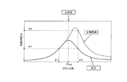
- FIG. 2 is a graph showing the relationship between the in-cylinder pressure and the crank angle during normal combustion and misfire occurrence.
- the in-cylinder pressure rises due to combustion even after the piston 4 reaches top dead center when shifting from the compression stroke to the explosion stroke.
- the pressure does not increase due to combustion. Therefore, the pressure peaks at the top dead center where the volume in the cylinder 3 is minimized, and the pressure decreases after the top dead center. That is, the waveform of the cylinder pressure at the time of misfire is substantially symmetrical about the top dead center.
- the cylinder internal pressure at a predetermined crank angle ⁇ 1 in the compression stroke before reaching the top dead center is P1 (hereinafter, P1 is referred to as the first cylinder internal pressure), and the explosion stroke after reaching the top dead center.
- P1 is referred to as the first cylinder internal pressure
- P2 is referred to as the second cylinder internal pressure
- the occurrence of misfire can be determined by comparing the value with the threshold value ⁇ .
- the difference between ⁇ TDC and ⁇ 1 (that is, the difference between ⁇ TDC and ⁇ 2) is preferably in the range of 5 ° to 45 °.
- Equation 1 when satisfying Equation 1, it is determined that the combustion is normal, and when Equation 2 is satisfied, it is determined that misfire has occurred.
- the threshold value ⁇ at this time is changed according to the load of the generator 30 as will be described later.
- FIG. 3 is a drawing for explaining the flow of misfire determination in the misfire determination device 24.
- the misfire determination device 24 receives the in-cylinder pressure from the in-cylinder pressure sensor 25 and the crank angle from the crank angle detection device 23, and the in-cylinder pressure and the crank angle as shown in FIG. Data indicating the relationship is acquired (S1).
- the load (generator output) of the generator 30 is estimated (S3).
- the load is estimated based on the following principle.
- the correlation between the first cylinder pressure P1 and the load is obtained in advance by experiments, calculations, and the like under the same conditions as when the gas engine 2 actually generates power, and the misfire determination device 24.
- the misfire determination apparatus 24 can estimate the load from the first cylinder pressure P1. Therefore, in S3 of FIG. 3, the load of the generator 30 is estimated from the first cylinder pressure P1 detected by the cylinder pressure sensor 25 using the relationship shown in FIG. Accordingly, the in-cylinder pressure sensor 25 also serves as load information detection means, and also serves to detect the first cylinder pressure P1 as a value correlated with the load.
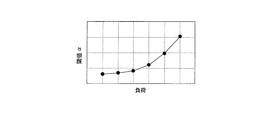
- the misfire determination device 24 determines a threshold value ⁇ according to the estimated load (S4). Specifically, the misfire determination device 24 stores a correspondence relationship between the load and the threshold value ⁇ as shown in FIG. 5, and this correspondence relationship is set so that the threshold value ⁇ increases as the load increases. Yes.
- the threshold value ⁇ is appropriately changed according to the load of the generator 30, and therefore misfire in the gas engine 2 compared to the case where the threshold value ⁇ is constant regardless of the load. It is possible to accurately determine the occurrence of. Further, since the threshold value ⁇ is set small when the load on the generator 30 is small, the second cylinder internal pressure P2 in the explosion stroke at the time of normal combustion, and at the time of misfire occurrence, as in the low load operation at the time of startup or the like When the difference from the second cylinder pressure P2 in the explosion stroke is small, it is possible to prevent erroneous determination that the normal combustion is misfire.
- the threshold value ⁇ is set to be large when the load on the generator 30 is large, it is erroneously determined that no misfire has occurred even when a bad combustion state that should be determined as misfire occurs during high load operation. Can be prevented. Furthermore, since the first cylinder pressure P1 in the compression stroke is used as a value correlated with the load of the generator 30, and the threshold value ⁇ is changed according to the first cylinder pressure P1, the generator 30 It is not necessary to detect the load directly and input it to the misfire determination device 24, and the system can be simplified.
- the air-fuel ratio of the gas engine 2 is controlled to be substantially constant.
- the air-fuel ratio may be controlled to change.
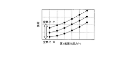
- the correspondence data as shown in FIG. 6 is used instead of the correspondence data as shown in FIG.
- the air amount increases as the air-fuel ratio increases, and the value of the first cylinder pressure P1 in the compression stroke increases.
- the air-fuel ratio is small, the amount of air is small, and the value of the first cylinder pressure P1 in the compression stroke is small.
- the correlation between the first in-cylinder pressure P1 and the load shown in FIG. 6 is obtained in advance by performing experiments, calculations, and the like for each air-fuel ratio, and the misfire determination device 24 obtains a high-order approximation obtained from the correlation. Functions and table functions are stored. Thereby, the misfire determination apparatus 24 can estimate the load from the first cylinder pressure P1 with reference to the data corresponding to the current air-fuel ratio in FIG.
- the load is obtained from the first cylinder pressure P1 according to FIG. 4 (or FIG. 6), and the threshold value ⁇ is obtained from the load, but the threshold value ⁇ is directly obtained from the first cylinder pressure P1. May be requested.
- the difference between the second cylinder pressure P2 and the first cylinder pressure P1 is compared with the threshold value ⁇ , but the ratio between the second cylinder pressure P2 and the first cylinder pressure P1 is compared. May be compared with a threshold value.
- the load is estimated from the first cylinder pressure P1, but the load measured directly from the generator 30 by the load detection sensor may be input to the misfire determination device 24.
Landscapes
- Engineering & Computer Science (AREA)
- Chemical & Material Sciences (AREA)
- Combustion & Propulsion (AREA)
- Mechanical Engineering (AREA)
- General Engineering & Computer Science (AREA)
- Chemical Kinetics & Catalysis (AREA)
- General Chemical & Material Sciences (AREA)
- Oil, Petroleum & Natural Gas (AREA)
- Combined Controls Of Internal Combustion Engines (AREA)
- Control Of Vehicle Engines Or Engines For Specific Uses (AREA)
Abstract
発電機(30)を駆動するガスエンジン(2)の失火を判定するシステム(1)であって、ガスエンジン(2)の気筒(3)の内部圧力である気筒内圧力を検出可能な筒内圧センサ(25)と、気筒(3)が圧縮行程にあるときに筒内圧センサ(25)で検出される第1気筒内圧力P1と、気筒(3)が爆発行程にあるときに筒内圧センサ(25)で検出される第2気筒内圧力P2との差ΔP(=P2-P1)を閾値αと比較することにより、気筒(3)の失火を判定する失火判定装置(24)と、を備え、失火判定装置(24)は、筒内圧センサ(25)で検出される第1気筒内圧力P1(負荷に相関関係のある値)に応じて閾値αを変更する。
Description
本件出願は、2009年3月12日に日本特許庁に出願された特願2009-60090の優先権を主張するものであり、その全体を参照することにより本件出願の一部となすものとして引用する。
本発明は、発電機を駆動するエンジンの失火を判定するためのエンジン失火判定システム及び方法に関するものである。
近年、工場等において、電力会社から供給される系統電力と、工場内に定置されたガスエンジンで発電機を駆動して得られる発電電力とを連係させて使用する電力システムが提供されている。ガスエンジンは、リーン状態で燃焼が行われるとエネルギー効率が良好であり、一定負荷で運転する発電設備に用いるのに適している。このガスエンジンの運転においては、圧縮行程から爆発行程に移行する際に混合気が着火されない失火が発生すると望ましくないため、失火発生を正しく把握してそれに対処する必要がある。
エンジンの失火を判定するための技術としては、正常燃焼時と失火発生時とで気筒内の圧力波形が異なることを利用し、エンジンの気筒内圧力から失火の発生を判定する装置が知られている(例えば、特開昭57-80538号公報及び特開2003-13793号公報参照)。正常燃焼時には、着火された混合気の燃焼によって気筒内で圧力増加が生じるため、気筒内のピストンが上死点に達した後に気筒内圧力が増加することとなる。これに対して、失火発生時には、燃料による圧力増加が発生しないため、上死点において気筒内圧力が最大となり、その後は気筒内圧力が減少する。よって、前記装置は、圧縮行程での気筒内圧力と、上死点以降の爆発行程での気筒内圧力とを検出し、これら気筒内圧力の比を所定の閾値と比較して失火の発生を判定するようにしている。
ところで、発電用エンジンでは、起動時において失火の有無を判定し、失火が発生すれば運転を停止して再び起動をやり直すようにしている。その場合、起動時の低負荷運転では、正常燃焼時における上死点以降の気筒内圧力と、失火発生時における上死点以降の気筒内圧力との差が小さいため、閾値を十分に小さな値に設定しないと、正常燃焼時を失火であると誤判定する可能性がある。一方、高負荷運転時(定格運転時)には、閾値を小さくし過ぎると、失火と判定すべき燃焼状態の悪い状態が発生しても、失火が発生したと判定されない可能性がある。また、高負荷運転時において、気筒内圧力を検出するセンサに誤差が生じた場合にも、閾値を小さくし過ぎると、正しく失火が判定されない可能性がある。
そこで本発明は、発電用エンジンにおける失火の発生を正確に判定することを目的としている。
本発明に係るエンジン失火判定システムは、発電機を駆動するエンジンの失火を判定する装置であって、前記エンジンの気筒の内部圧力である気筒内圧力を検出可能な圧力検出手段と、前記気筒が圧縮行程にあるときに前記圧力検出手段で検出される第1気筒内圧力と、前記気筒が爆発行程にあるときに前記圧力検出手段で検出される第2気筒内圧力との差又は比を閾値と比較することにより、前記気筒の失火を判定する失火判定手段と、前記発電機の負荷又は前記発電機の負荷に相関関係のある値を検出可能な負荷情報検出手段と、を備え、前記失火判定手段は、前記負荷情報検出手段で検出される前記負荷又は前記負荷に相関関係のある値に応じて前記閾値を変更することを特徴とする。
前記構成によれば、発電機の負荷に応じて閾値が適宜変更されることになるので、負荷に関係なく閾値を一定とした場合に比べて、エンジンでの失火の発生を正確に判定することが可能となる。
前記失火判定手段は、前記負荷情報検出手段で検出される前記負荷又は前記負荷に相関関係のある値が大きくなるにつれて前記閾値を大きくするように構成されてもよい。
前記構成によれば、発電機の負荷が小さいときには閾値が小さく設定されるので、起動時等の低負荷運転のように、正常燃焼時における爆発行程での気筒内圧力と、失火発生時における爆発行程での気筒内圧力との差が小さい場合において、正常燃焼時を失火であると誤判定することを防止することができる。かつ、発電機の負荷が大きいときには閾値が大きく設定されるので、高負荷運転時において、失火と判定すべき燃焼状態の悪い状態が発生しても、失火が発生していないと誤判定することを防止することができる。
前記気筒が圧縮行程にあるときの気筒内圧力と前記負荷とが相関関係を有するように前記気筒に供給される混合気の空燃比を制御する空燃比制御手段をさらに有し、前記圧力検出手段は、前記負荷情報検出手段を兼ねており、前記負荷情報検出手段は、前記負荷に相関関係のある値として前記気筒が圧縮行程にあるときの気筒内圧力を検出するように構成されていてもよい。
前記構成によれば、圧縮行程の気筒内圧力と発電機の負荷とが相関関係を有するように空燃比を制御されている場合(例えば、空燃比が一定の場合等)には、気筒内圧力に応じて閾値を変更し、負荷情報検出手段を圧力検出手段と別個に設ける必要がなくなるので、システムを簡素化することができる。
また本発明のエンジン失火判定方法は、発電機を駆動するエンジンの失火を判定する方法であって、前記エンジンの気筒が圧縮行程にあるときに第1気筒内圧力を検出し、前記エンジンの気筒が爆発行程にあるときに第2気筒内圧力を検出し、前記第1気筒内圧力と前記第2気筒内圧力との差又は比を閾値と比較することにより、前記気筒の失火を判定し、前記発電機の負荷又は前記発電機の負荷に相関関係のある値に応じて前記閾値を変更することを特徴とする。
前記方法によれば、発電機の負荷に応じて閾値が適宜変更されることになるので、負荷に関係なく閾値を一定とした場合に比べて、エンジンでの失火の発生を正確に判定することが可能となる。
以下、本発明に係る実施形態を図面を参照して説明する。
図1は本発明の実施形態に係るガスエンジンの失火判定システム1を示した構成図である。図1に示すように、ガスエンジン2は、天然ガスや都市ガス等のガス燃料を主燃料とするレシプロ型の多気筒4ストロークエンジンであり、発電機30を駆動する原動機として使用されている。図1ではガスエンジン2の気筒3の1つを代表して示しているが、図示しない他の気筒も同様の構成となっている。
気筒3にはピストン4が往復動可能に挿入されており、ピストン4は出力軸であるクランク軸29と連結されている。このクランク軸29は、発電機30の入力軸に駆動力を伝達するように接続されている。気筒3内におけるピストン4の上方は主燃焼室5をなしてある。主燃焼室5には、給気弁6を介して給気ポート7が接続されるとともに、排気弁8を介して排気ポート9が接続されている。給気ポート7内にはガス燃料を噴射する主燃料ガス供給弁10が設けられている。また、主燃焼室5には副燃焼室11が隣接している。副燃焼室11は、隔壁12を介して主燃焼室5と区画され、隔壁12に形成された連通孔13を介して主燃焼室5と連通している。この副燃焼室11にはガス燃料を噴射する副燃料ガス供給弁14と、混合気を燃焼させるための点火プラグ15とが設けられている。
このガスエンジン2によれば、給気行程において、主燃焼室5には給気ポート7から空気と主燃料ガス供給弁10が噴射するガス燃料とを含む混合気が供給され、副燃焼室11には副燃料ガス供給弁14が噴射するガス燃料を含む混合気が供給される。圧縮行程において主燃焼室5及び副燃焼室11内の混合気が圧縮された後、点火プラグ15が所定のタイミングで動作して副燃焼室11内の混合気が着火される。副燃焼室11内で発生した火炎は連通孔13を通じて主燃焼室5内に伝播し、主燃焼室5内の混合気が着火される。これによりピストン4が押し下げられる(膨張行程)。そして、排気行程において、主燃焼室5内のガスは排気ポート9を介して外部に排出される。なお、排気ポート9に接続される排気通路16は、過給機(図示せず)に接続される第1排気通路17と、外部に開放される第2排気通路18とに分岐されており、第2排気通路18には給気圧を調整するための調整弁19が設けられている。
失火判定システム1は、CPU、記憶装置及び入出力インターフェース等を有する主制御装置20を備えている。主制御装置20は、主燃料ガス供給弁10及び副燃料ガス供給弁14を駆動するガス弁制御装置21に接続され、このガス弁制御装置21に指令信号を出力して各燃料ガス供給弁10,14を駆動制御する。また、主制御装置20は、点火プラグ15を駆動する点火プラグドライバ22に接続されている。主制御装置20は、このドライバ22に指令信号を出力して点火プラグ15を駆動制御し、これにより混合気の着火タイミングを制御する。また、主制御装置20には、給気圧、給気温度などが入力されるようになっている。主制御装置20は、空燃比が略一定となるように給気圧を制御するために調整弁19の開度を調節する機能を有する。即ち、主制御装置20が、空燃比制御手段を構成している。
失火判定システム1は、ガスエンジン2のクランク角を検知するためのクランク角検知装置23を備え、主制御装置20にはクランク角検知装置23からのクランク角情報が入力されるようになっている。クランク角検知装置23には、例えば、ロータリーエンコーダ等が用いられ、その場合にはエンコーダパルス信号(回転数パルス信号)及びリセット信号(1サイクルに一度出力される信号)によりクランク角が検知されることとなる。
失火判定システム1は、圧縮行程から爆発行程に移行する際に気筒3にて混合気が正常に燃焼されない現象である失火の発生を判定する失火判定装置24(失火判定手段)を備えている。この失火判定装置24には、クランク角検知装置23と、気筒3の内部圧力である気筒内圧力を検出する筒内圧センサ25(圧力検出手段)とが接続されている。失火判定装置24は、クランク角検知装置23で検知されたクランク角と、筒内圧センサ25で検出された気筒内圧力とに基づいて気筒3での失火の発生を判定する。
次に、失火判定装置24による失火判定の原理を説明する。図2は正常燃焼時及び失火発生時における気筒内圧力とクランク角との関係を表したグラフである。図2に示すように、ガスエンジン2の正常燃焼時には、圧縮行程から爆発行程に移行する際においてピストン4が上死点に達した後も、燃焼により気筒内圧力は上昇する。一方、ガスエンジン2で失火が発生した時には、燃焼による圧力上昇が生じないため、気筒3内の容積が最小なる上死点で圧力がピークとなり、上死点の後は圧力が減少する。つまり、失火発生時における気筒内圧力の波形は上死点を中心として略対称となる。
このため、上死点に達する前の圧縮行程における所定のクランク角θ1での気筒内圧力をP1(以下、P1を第1気筒内圧力と称す)とし、上死点に達した後の爆発行程における所定のクランク角θ2での気筒内圧力をP2(以下、P2を第2気筒内圧力と称す)としたときの、第2気筒内圧力P2と第1気筒内圧力P1との圧力差ΔPの値を閾値αと比較することによって、失火の発生を判定することができる。
具体的には、上死点のクランク角θTDCとクランク角θ1との差が、クランク角θ2と上死点のクランク角θTDCとの差に等しくなるようにθ1及びθ2を設定する。なお、θTDCとθ1との差(すなわちθTDCとθ2との差)は、5°~45°の範囲内にあることが望ましい。θTDCとθ1との差が小さすぎると、燃焼遅れが発生した場合に、P1とP2との差が小さくなって、失火と燃焼との区別ができない可能性がある一方、θTDCとθ1との差が大きすぎると、燃焼の影響がP2に現れずにP1とP2との差が小さくなって、失火と燃焼との区別ができない可能性があるためである。なお、5°~45°との具体的な数値は、実験結果から得られたものである。
そして、数式1を満たすときには正常燃焼であると判定し、数式2を満たすときには失火発生と判定する。この際の閾値αは、後述するように発電機30の負荷に応じて変更される。
ΔP=P2-P1>α
ΔP=P2-P1≦α
図3は失火判定装置24における失火判定の流れを説明する図面である。図3に示すように、失火判定装置24は、筒内圧センサ25から気筒内圧力を受信するとともに、クランク角検知装置23からクランク角を受信し、図2に示すような気筒内圧力とクランク角との関係を示すデータを取得する(S1)。次いで、そのデータからΔP(=P2-P1)を計算する(S2)。また、ΔPの計算と並行して、発電機30の負荷(発電機出力)を推定する(S3)。
図3は失火判定装置24における失火判定の流れを説明する図面である。図3に示すように、失火判定装置24は、筒内圧センサ25から気筒内圧力を受信するとともに、クランク角検知装置23からクランク角を受信し、図2に示すような気筒内圧力とクランク角との関係を示すデータを取得する(S1)。次いで、そのデータからΔP(=P2-P1)を計算する(S2)。また、ΔPの計算と並行して、発電機30の負荷(発電機出力)を推定する(S3)。
負荷の推定は、次のような原理で行われる。気筒3に供給される混合気の空燃比(=燃焼に必要な空気重量/投入する燃料重量)は、圧縮行程にあるときの第1気筒内圧力P1と発電機30の負荷とが相関関係を有するように主制御装置20により制御されている。具体的には、空燃比は略一定に保たれるよう制御されており、低負荷では気筒3に供給される燃料量及び空気量は少なく、高負荷では気筒3に供給される燃料量及び空気量は多くなる。よって、点火プラグ15により着火されるまでの圧縮行程における第1気筒内圧力P1は、低負荷では低く、高負荷では高くなるという関係が成立する。
そこで、図4に示すように、ガスエンジン2により実際に発電を行うときと同一条件において第1気筒内圧力P1と負荷との相関関係を予め実験や計算等から求めておき、失火判定装置24に当該相関関係から得られる高次の近似関数やテーブル関数等を記憶させている。これにより、失火判定装置24は、第1気筒内圧力P1から負荷を推定できるようになっている。よって、図3のS3では、図4に示すような関係を利用して、筒内圧センサ25で検出された第1気筒内圧力P1から発電機30の負荷を推定する。よって、筒内圧センサ25は、負荷情報検出手段を兼ねており、第1気筒内圧力P1を負荷に相関関係のある値として検出する役目も果たしている。
次いで、失火判定装置24は、推定された負荷に応じて閾値αを決定する(S4)。具体的には、失火判定装置24は、図5に示すような負荷と閾値αとの対応関係を記憶しており、この対応関係は負荷が大きくなるにつれて閾値αが大きくなるように設定されている。
次いで、失火判定装置24は、決定された閾値αとΔP(=P2-P1)との比較を行い、前述した数式1を満たすときには正常燃焼であると判定し、数式2を満たすときには失火発生と判定する(S5)。
以上に説明した構成によれば、発電機30の負荷に応じて閾値αが適宜変更されることになるので、負荷に関係なく閾値αを一定とした場合に比べて、ガスエンジン2での失火の発生を正確に判定することが可能となる。また、発電機30の負荷が小さいときには閾値αが小さく設定されるので、起動時等の低負荷運転のように、正常燃焼時における爆発行程での第2気筒内圧力P2と、失火発生時における爆発行程での第2気筒内圧力P2との差が小さい場合において、正常燃焼時を失火であると誤判定することを防止することができる。かつ、発電機30の負荷が大きいときには閾値αが大きく設定されるので、高負荷運転時において、失火と判定すべき燃焼状態の悪い状態が発生しても、失火が発生していないと誤判定することを防止することができる。さらに、発電機30の負荷に相関関係のある値として圧縮行程での第1気筒内圧力P1を用い、その第1気筒内圧力P1に応じて閾値αを変更しているため、発電機30の負荷を直接検出して失火判定装置24に入力する必要がなくなり、システムを簡素化することができる。
なお、前述した実施形態では、ガスエンジン2の空燃比を略一定に制御しているが、変形例として、空燃比を変化させるように制御してもよい。その場合には、図4のような対応データの代わりに、図6のような対応データを利用する。図6に示すように、負荷に対して燃料量はほぼ一意に決まるため、空燃比が大きいと空気量が多いことになり、圧縮行程の第1気筒内圧力P1の値は大きくなる。一方、空燃比が小さいと、空気量が少ないことになり、圧縮行程の第1気筒内圧力P1の値は小さくなる。
図6に示す第1気筒内圧力P1と負荷との相関関係は、空燃比ごとに実験や計算等を行うことで予め求めておき、失火判定装置24に当該相関関係から得られる高次の近似関数やテーブル関数等を記憶させている。これにより、失火判定装置24は、図6のうち現在の空燃比に対応するデータを参照し、第1気筒内圧力P1から負荷を推定することができる。
また、前述した実施形態では、図4(又は図6)により第1気筒内圧力P1から負荷を求め、その負荷から閾値αを求めているが、第1気筒内圧力P1から直接的に閾値αを求めるようにしてもよい。また、前述した実施形態では、第2気筒内圧力P2と第1気筒内圧力P1との差を閾値αと比較しているが、第2気筒内圧力P2と第1気筒内圧力P1との比を閾値と比較するようにしてもよい。また、前述した実施形態では、第1気筒内圧力P1から負荷を推定しているが、負荷検出センサにより発電機30から直接計測した負荷を失火判定装置24に入力するようにしてもよい。
Claims (4)
- 発電機を駆動するエンジンの失火を判定するシステムであって、
前記エンジンの気筒の内部圧力である気筒内圧力を検出可能な圧力検出手段と、
前記気筒が圧縮行程にあるときに前記圧力検出手段で検出される第1気筒内圧力と、前記気筒が爆発行程にあるときに前記圧力検出手段で検出される第2気筒内圧力との差又は比を閾値と比較することにより、前記気筒の失火を判定する失火判定手段と、
前記発電機の負荷又は前記発電機の負荷に相関関係のある値を検出可能な負荷情報検出手段と、を備え、
前記失火判定手段は、前記負荷情報検出手段で検出される前記負荷又は前記負荷に相関関係のある値に応じて前記閾値を変更することを特徴とするエンジン失火判定システム。 - 前記失火判定手段は、前記負荷情報検出手段で検出される前記負荷又は前記負荷に相関関係のある値が大きくなるにつれて前記閾値を大きくするように構成されている請求項1に記載のエンジン失火判定システム。
- 前記気筒が圧縮行程にあるときの気筒内圧力と前記負荷とが相関関係を有するように前記気筒に供給される混合気の空燃比を制御する空燃比制御手段をさらに有し、
前記圧力検出手段は、前記負荷情報検出手段を兼ねており、
前記負荷情報検出手段は、前記負荷に相関関係のある値として前記気筒が圧縮行程にあるときの気筒内圧力を検出するように構成されている請求項1に記載のエンジン失火判定システム。 - 発電機を駆動するエンジンの失火を判定する方法であって、
前記エンジンの気筒が圧縮行程にあるときに第1気筒内圧力を検出し、
前記エンジンの気筒が爆発行程にあるときに第2気筒内圧力を検出し、
前記第1気筒内圧力と前記第2気筒内圧力との差又は比を閾値と比較することにより、前記気筒の失火を判定し、
前記発電機の負荷又は前記発電機の負荷に相関関係のある値に応じて前記閾値を変更することを特徴とするエンジン失火判定方法。
Applications Claiming Priority (2)
| Application Number | Priority Date | Filing Date | Title |
|---|---|---|---|
| JP2009-060090 | 2009-03-12 | ||
| JP2009060090A JP5314464B2 (ja) | 2009-03-12 | 2009-03-12 | エンジン失火判定システム及び方法 |
Publications (1)
| Publication Number | Publication Date |
|---|---|
| WO2010103778A1 true WO2010103778A1 (ja) | 2010-09-16 |
Family
ID=42728074
Family Applications (1)
| Application Number | Title | Priority Date | Filing Date |
|---|---|---|---|
| PCT/JP2010/001589 Ceased WO2010103778A1 (ja) | 2009-03-12 | 2010-03-08 | エンジン失火判定システム及び方法 |
Country Status (2)
| Country | Link |
|---|---|
| JP (1) | JP5314464B2 (ja) |
| WO (1) | WO2010103778A1 (ja) |
Cited By (4)
| Publication number | Priority date | Publication date | Assignee | Title |
|---|---|---|---|---|
| WO2013010195A1 (de) * | 2011-07-20 | 2013-01-24 | Ge Jenbacher Gmbh & Co Og | Verfahren zum betreiben einer stationären kraftanlage |
| CN104919298A (zh) * | 2013-01-14 | 2015-09-16 | 卡明斯公司 | 基于排气歧管压力的内燃发动机不点火检测 |
| CN105264204A (zh) * | 2013-06-05 | 2016-01-20 | 丰田自动车株式会社 | 用于内燃机的失火检测系统 |
| CN108644034A (zh) * | 2018-05-18 | 2018-10-12 | 山东大学 | 基于臭氧助燃的大功率稀燃天然气发动机燃烧系统及方法 |
Families Citing this family (1)
| Publication number | Priority date | Publication date | Assignee | Title |
|---|---|---|---|---|
| EP3726036A1 (de) * | 2019-04-15 | 2020-10-21 | Winterthur Gas & Diesel AG | Verfahren zum betreiben eines grossmotors sowie grossmotor |
Citations (5)
| Publication number | Priority date | Publication date | Assignee | Title |
|---|---|---|---|---|
| JP2002202000A (ja) * | 2000-12-28 | 2002-07-19 | Fuji Heavy Ind Ltd | エンジンの失火検出装置 |
| WO2002079629A1 (en) * | 2001-03-30 | 2002-10-10 | Mitsubishi Heavy Industries, Ltd. | Internal combustion engine combustion diagnosis/control apparatus and combustion diagnosis/control method |
| JP2006152895A (ja) * | 2004-11-29 | 2006-06-15 | Honda Motor Co Ltd | 失火検出装置 |
| JP2007198325A (ja) * | 2006-01-30 | 2007-08-09 | Nissan Motor Co Ltd | 筒内直接噴射式火花点火内燃機関の制御装置 |
| JP2008223669A (ja) * | 2007-03-14 | 2008-09-25 | Nissan Motor Co Ltd | エンジン負荷推定装置及びエンジン負荷推定方法 |
-
2009
- 2009-03-12 JP JP2009060090A patent/JP5314464B2/ja active Active
-
2010
- 2010-03-08 WO PCT/JP2010/001589 patent/WO2010103778A1/ja not_active Ceased
Patent Citations (5)
| Publication number | Priority date | Publication date | Assignee | Title |
|---|---|---|---|---|
| JP2002202000A (ja) * | 2000-12-28 | 2002-07-19 | Fuji Heavy Ind Ltd | エンジンの失火検出装置 |
| WO2002079629A1 (en) * | 2001-03-30 | 2002-10-10 | Mitsubishi Heavy Industries, Ltd. | Internal combustion engine combustion diagnosis/control apparatus and combustion diagnosis/control method |
| JP2006152895A (ja) * | 2004-11-29 | 2006-06-15 | Honda Motor Co Ltd | 失火検出装置 |
| JP2007198325A (ja) * | 2006-01-30 | 2007-08-09 | Nissan Motor Co Ltd | 筒内直接噴射式火花点火内燃機関の制御装置 |
| JP2008223669A (ja) * | 2007-03-14 | 2008-09-25 | Nissan Motor Co Ltd | エンジン負荷推定装置及びエンジン負荷推定方法 |
Cited By (8)
| Publication number | Priority date | Publication date | Assignee | Title |
|---|---|---|---|---|
| WO2013010195A1 (de) * | 2011-07-20 | 2013-01-24 | Ge Jenbacher Gmbh & Co Og | Verfahren zum betreiben einer stationären kraftanlage |
| CN103717853A (zh) * | 2011-07-20 | 2014-04-09 | Ge延巴赫两合无限公司 | 用于运行固定的发电站的方法 |
| US8936005B2 (en) | 2011-07-20 | 2015-01-20 | Ge Jenbacher Gmbh & Co Og | Method for operating a stationary power generating plant |
| AT511734B1 (de) * | 2011-07-20 | 2016-02-15 | Ge Jenbacher Gmbh & Co Ohg | Verfahren zum betreiben einer stationären kraftanlage |
| CN104919298A (zh) * | 2013-01-14 | 2015-09-16 | 卡明斯公司 | 基于排气歧管压力的内燃发动机不点火检测 |
| CN104919298B (zh) * | 2013-01-14 | 2017-08-22 | 卡明斯公司 | 基于排气歧管压力的内燃发动机不点火检测 |
| CN105264204A (zh) * | 2013-06-05 | 2016-01-20 | 丰田自动车株式会社 | 用于内燃机的失火检测系统 |
| CN108644034A (zh) * | 2018-05-18 | 2018-10-12 | 山东大学 | 基于臭氧助燃的大功率稀燃天然气发动机燃烧系统及方法 |
Also Published As
| Publication number | Publication date |
|---|---|
| JP5314464B2 (ja) | 2013-10-16 |
| JP2010209892A (ja) | 2010-09-24 |
Similar Documents
| Publication | Publication Date | Title |
|---|---|---|
| EP2700804B1 (en) | Gas engine, gas engine control apparatus, and gas engine control method | |
| US9140229B2 (en) | Knocking control system for gas engine | |
| CN107709956B (zh) | 检测和缓解异常燃烧特性 | |
| RU2423618C2 (ru) | Датчик действительного качества топлива | |
| US7461633B2 (en) | Method of controlling the combustion phase of an internal-combustion engine, notably a gasoline type direct-injection supercharged engine | |
| JP5424944B2 (ja) | 内燃機関の制御装置 | |
| US7854218B2 (en) | Method to recognize and avoid premature combustion events | |
| US8374772B2 (en) | Misfire detection through combustion pressure sensor | |
| US9964053B2 (en) | Combustion control device for gas engine | |
| CN102667112A (zh) | 识别内燃机中不受控燃烧的方法和设备 | |
| CN104863712A (zh) | 运行气体燃料的内燃发动机中的失火检测 | |
| JP5314464B2 (ja) | エンジン失火判定システム及び方法 | |
| EP4050199B1 (en) | Internal combustion engine control device | |
| CN112682241A (zh) | 发动机点火正时的控制方法及装置 | |
| JP4096942B2 (ja) | 内燃機関の燃料噴射制御装置 | |
| JP2008196409A (ja) | 内燃機関の燃焼制御装置 | |
| JP2013104371A (ja) | 内燃機関の制御装置 | |
| JP5949075B2 (ja) | 内燃機関の制御装置 | |
| US10393609B2 (en) | System and method for detection of changes to compression ratio and peak firing pressure of an engine | |
| JP2012219757A (ja) | 内燃機関の制御装置 | |
| US20260063099A1 (en) | Systems and methods for adaptively managing engine knocking | |
| JP2009085072A (ja) | 内燃機関の制御装置 | |
| JP2021025507A (ja) | エンジン用オイルアップ検知システムおよびエンジン用オイルアップ検知方法 | |
| JP2007278088A (ja) | 内燃機関の燃料噴射制御装置 |
Legal Events
| Date | Code | Title | Description |
|---|---|---|---|
| 121 | Ep: the epo has been informed by wipo that ep was designated in this application |
Ref document number: 10750536 Country of ref document: EP Kind code of ref document: A1 |
|
| NENP | Non-entry into the national phase |
Ref country code: DE |
|
| 122 | Ep: pct application non-entry in european phase |
Ref document number: 10750536 Country of ref document: EP Kind code of ref document: A1 |