WO2010100750A1 - トリクロロシラン冷却塔およびそれを用いたトリクロロシラン製造方法 - Google Patents
トリクロロシラン冷却塔およびそれを用いたトリクロロシラン製造方法 Download PDFInfo
- Publication number
- WO2010100750A1 WO2010100750A1 PCT/JP2009/054271 JP2009054271W WO2010100750A1 WO 2010100750 A1 WO2010100750 A1 WO 2010100750A1 JP 2009054271 W JP2009054271 W JP 2009054271W WO 2010100750 A1 WO2010100750 A1 WO 2010100750A1
- Authority
- WO
- WIPO (PCT)
- Prior art keywords
- cooling
- trichlorosilane
- reaction product
- product gas
- tetrachlorosilane
- Prior art date
- Legal status (The legal status is an assumption and is not a legal conclusion. Google has not performed a legal analysis and makes no representation as to the accuracy of the status listed.)
- Ceased
Links
Images
Classifications
-
- C—CHEMISTRY; METALLURGY
- C01—INORGANIC CHEMISTRY
- C01B—NON-METALLIC ELEMENTS; COMPOUNDS THEREOF; METALLOIDS OR COMPOUNDS THEREOF NOT COVERED BY SUBCLASS C01C
- C01B33/00—Silicon; Compounds thereof
- C01B33/08—Compounds containing halogen
- C01B33/107—Halogenated silanes
-
- C—CHEMISTRY; METALLURGY
- C01—INORGANIC CHEMISTRY
- C01B—NON-METALLIC ELEMENTS; COMPOUNDS THEREOF; METALLOIDS OR COMPOUNDS THEREOF NOT COVERED BY SUBCLASS C01C
- C01B33/00—Silicon; Compounds thereof
- C01B33/08—Compounds containing halogen
- C01B33/107—Halogenated silanes
- C01B33/1071—Tetrachloride, trichlorosilane or silicochloroform, dichlorosilane, monochlorosilane or mixtures thereof
-
- F—MECHANICAL ENGINEERING; LIGHTING; HEATING; WEAPONS; BLASTING
- F28—HEAT EXCHANGE IN GENERAL
- F28C—HEAT-EXCHANGE APPARATUS, NOT PROVIDED FOR IN ANOTHER SUBCLASS, IN WHICH THE HEAT-EXCHANGE MEDIA COME INTO DIRECT CONTACT WITHOUT CHEMICAL INTERACTION
- F28C3/00—Other direct-contact heat-exchange apparatus
- F28C3/06—Other direct-contact heat-exchange apparatus the heat-exchange media being a liquid and a gas or vapour
Definitions
- the present invention relates to a trichlorosilane cooling tower used for producing trichlorosilane from tetrachlorosilane and hydrogen, and a method for producing trichlorosilane using the trichlorosilane cooling tower.
- Trichlorosilane (SiHCl 3 ) is a special material gas used for manufacturing semiconductors, liquid crystal panels, solar cells, and the like. In recent years, demand has been steadily expanding, and growth is expected as a CVD material widely used in the electronics field.
- Trichlorosilane is produced by contacting tetrachlorosilane (SiCl 4 ) and hydrogen (H 2 ) to achieve the following thermal equilibrium state. SiCl 4 + H 2 ⁇ SiHCl 3 + HCl (1) This reaction is performed by heating a raw material gas composed of gasified tetrachlorosilane and hydrogen to 700 ° C. to 1400 ° C. in a reaction furnace.
- the high-temperature reaction product gas discharged from the reaction furnace contains a large amount of unreacted tetrachlorosilane and hydrogen in addition to the produced trichlorosilane and hydrogen chloride.
- a method of condensing in a distillation column using the difference in boiling point between tetrachlorosilane and trichlorosilane is used. Specifically, it is divided into chlorosilane, which is a condensed component, and hydrogen chloride, hydrogen, and non-condensed chlorosilane, which are uncondensed by a condenser, and the condensed component is cooled to about -70 ° C. by cryogenic separation. Isolate the chlorosilane.
- trichlorosilane comprising a step of reacting tetrachlorosilane with hydrogen to convert to trichlorosilane and further cooling the reaction product gas
- Patent Document 1 a method for producing trichlorosilane comprising a step of reacting tetrachlorosilane with hydrogen to convert to trichlorosilane and further cooling the reaction product gas
- tetrachlorosilane and hydrogen are introduced into a reaction chamber and reacted at a temperature of 800 ° C. or higher to generate a mixed gas containing trichlorosilane and hydrogen chloride;
- the method has a step of cooling the mixed gas by introducing a cooling gas mainly composed of at least one of hydrogen, tetrachlorosilane, or hydrogen chloride into the mixed gas.
- Patent Document 2 discloses that a reaction product gas containing trichlorosilane and hydrogen chloride is obtained by introducing tetrachlorosilane and hydrogen into a reaction chamber and performing a conversion reaction at a temperature of 600 ° C. to 1200 ° C., and then from the reaction chamber.
- An apparatus comprising a cooling means for spraying a chlorosilane mixture cooled to room temperature onto the derived reaction product gas and rapidly cooling to 300 ° C. or less within 1 second has been proposed.
- Patent Document 2 describes that a reaction mixture (chlorosilane mixture) obtained by the reaction is cooled to room temperature and used as a cooling liquid. Specific conditions for spraying a cooling liquid made of a chlorosilane mixture are described. There is no formal disclosure.
- the present invention has been made in view of the above circumstances, and is excellent in the cooling efficiency of the reaction product gas containing trichlorosilane without greatly changing the existing equipment and increasing the load required for cooling. It is an object of the present invention to provide a trichlorosilane cooling tower excellent in the recovery efficiency of trichlorosilane that does not cause raw materials and a method for producing trichlorosilane using the same.
- the trichlorosilane cooling tower of the present invention is A coolant having an average droplet diameter of 2000 ⁇ m or less is sprayed on a reaction product gas containing trichlorosilane obtained by reacting a raw material gas containing tetrachlorosilane and hydrogen at a temperature in the range of 700 to 1400 ° C.
- a primary cooling means that rapidly cools to a temperature range of 70 to 600 ° C., and a cooling liquid sprayed on the reaction product gas after the primary cooling provided above the primary cooling means and cooled to a temperature range of 30 to 60 ° C.
- the method for producing trichlorosilane of the present invention includes: Producing a reaction product gas containing trichlorosilane obtained by reacting a raw material gas containing tetrachlorosilane and hydrogen at a temperature in the range of 700 to 1400 ° C .; A primary cooling step of spraying the reaction product gas with a cooling liquid having an average droplet particle diameter of 2000 ⁇ m or less and rapidly cooling to 70 to 600 ° C. within 1 second; A secondary cooling step of further spraying a cooling liquid onto the reaction product gas after the primary cooling to cool the reaction product gas to a range of 30 to 60 ° C .; Have
- the cooling means is provided in multiple stages, and the temperature sufficient for freezing the equilibrium in the primary cooling step is 70 to 600.
- the trichlorosilane can be efficiently recovered in the gaseous state by rapidly cooling to 0 ° C. and by gently cooling to the range of 30 to 60 ° C. in order to condense the high boiling point polymer exclusively in the secondary cooling step.
- the trichlorosilane cooling tower and the trichlorosilane production method using the same since the cooling efficiency of the reaction product gas is extremely excellent, the equilibrium state tilted to trichlorosilane can be frozen instantly and reliably. it can. In addition, since trichlorosilane and the high-boiling point polymer can be separated and taken out, the trichlorosilane distillation load can be reduced. Furthermore, by providing the cooling means in multiple stages, more trichlorosilane can be taken out in a gaseous state. Thus, the synergistic action of these can greatly improve the productivity of trichlorosilane.
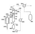
- FIG. 1 schematically shows an apparatus for carrying out a trichlorosilane cooling tower of this embodiment and a method for producing trichlorosilane using the same.
- the trichlorosilane cooling tower 100 of the present embodiment includes a substantially cylindrical metal container 101, a primary spray nozzle 102 and a secondary spray nozzle 103 that are installed in the container and spray a coolant in the container, and the primary spray.
- a primary cooling liquid supply pipe 104 and a secondary cooling liquid supply pipe 105 that are connected to the nozzle 102 and the secondary spray nozzle 103, respectively, and supply a cooling liquid thereto, and are connected to the primary spray nozzle 102 inside the metal container 101.
- a quenching pipe 106 and a filling member 107 installed between the primary spray nozzle 102 and the secondary spray nozzle 103.
- the metal container 101 is not particularly limited as long as it is a material that does not react with the reaction product gas, and can typically be made of a metal such as stainless steel.
- a reaction product gas introduction opening 108 for taking in the reaction product gas is provided on the side wall of the metal container 101.
- a cooling tower gas component extraction pipe 109 for extracting a gas component of the cooled reaction product gas is connected to the upper part of the metal container 101, and the bottom of the metal container 101 was used for cooling.
- a cooling tower liquid component extraction pipe 110 is connected to extract the cooling liquid and the condensate generated by cooling.
- the quenching tube 106 is not particularly limited as long as it does not react with the reaction product gas, and can typically be composed of a metal such as stainless steel.
- the quench pipe 106 is provided with an introduction opening 111 for taking in the reaction product gas at a position corresponding to the reaction product gas introduction opening 108 of the metal container 101. Further, the bottom of the quench pipe 106 is open on the entire surface, and a discharge opening 112 for discharging the cooled reaction product gas is formed.
- the primary spray nozzle 102 is installed from the canopy portion of the quench pipe 106 toward the inside of the quench pipe 106, and is connected to the primary coolant supply pipe 104.
- the primary spray nozzle 102 sprays the coolant toward the reaction product gas introduced from the introduction opening 111 of the quench pipe 106, and instantaneously reaches 70 to 600 ° C. where the equilibrium of the above formula (1) is frozen. Cool quickly.
- the primary spray nozzle 102 is not particularly limited as long as it can spray droplets having an average droplet particle diameter in a range of 2000 ⁇ m or less, and various types of nozzles can be used. In particular, a full-cone nozzle that can achieve a uniform flow distribution over the entire spray region is preferred.
- the average droplet particle size depends not only on the nozzle characteristics but also on the spraying conditions.
- the spray amount is 0.1 to 0.3 l / min
- the spray pressure is 0.1 to 0.2 MPa
- a mixed liquid composed of tetrachlorosilane and trichlorosilane having a mixing ratio described later is used as the cooling liquid, a liquid that can realize the above average droplet particle diameter is used.
- the filling member 107 is installed above the primary spray nozzle 102.
- the filling member 107 is provided with a gas passage so that the reaction product gas that is primarily cooled in the quench pipe 106 and pushed out from the discharge opening 112 of the quench pipe 106 is disturbed in its straight travel when rising inside the trichlorosilane cooling tower 100.
- Any form can be used as long as it is formed.
- it may be a form in which small blocks such as chips or blocks are packed irregularly, or a plurality of plate-like members provided with a large number of holes arranged at intervals.
- the filling member 107 is not particularly limited as long as it does not react with the reaction product gas, and can typically be made of a metal such as stainless steel.
- the secondary spray nozzle 103 is installed further above the primary spray nozzle 102 and the filling member 107, and is connected to the secondary coolant supply pipe 105.
- the secondary spray nozzle 103 is ejected from the discharge opening 112 of the quench pipe 106, rises in the trichlorosilane cooling tower 100, and sprays the coolant toward the reaction product gas passing through the filling member 107. Gently cool the temperature of the reaction product gas to the range of 30-60 ° C. while condensing the boiling polymer.
- the coolant sprayed from the secondary spray nozzle 103 also has a function of lowering the temperature inside the trichlorosilane cooling tower 100 and preventing the coolant from being vaporized before coming into contact with the reaction product gas.
- the secondary spray nozzle 103 is not particularly limited, and various types of nozzles can be used. In particular, a full-cone nozzle that can achieve a uniform flow distribution over the entire spray region is preferred.
- the average droplet diameter of the cooling liquid sprayed from the secondary spray nozzle 103 is not particularly limited, but is preferably in the range of 2000 ⁇ m or less, as in the case of the primary spray nozzle 102, because the cooling efficiency is excellent.
- a mixed liquid composed of tetrachlorosilane and trichlorosilane is preferably used, and the content of tetrachlorosilane in the mixed liquid is preferably 80 to 100 mol%, more preferably 85 to 95 mol%.
- the cooling liquid having such a specific composition the reaction can be frozen while the equilibrium of the above formula (1) is sufficiently moved to the right side, and trichlorosilane can be recovered with a high yield.
- the temperature of the coolant is preferably adjusted to 50 ° C. or lower. If the temperature of the cooling liquid is adjusted to 50 ° C. or less, the temperature of the reaction product gas can be rapidly cooled in a short time, so that the state of being sufficiently moved to the right side in the above equation (1) is maintained. The equilibrium can be frozen.
- a method for producing trichlorosilane using the above-described trichlorosilane cooling tower will be described with reference to FIG.
- a raw material gas in which gasified tetrachlorosilane and hydrogen are mixed is supplied to the bottom of the reaction furnace 201 through a raw material gas supply pipe 200.
- the reaction furnace 201 is made of graphite, and can be maintained in a state in which the interior of the reaction furnace 201 exceeds 700 ° C. and is not higher than 1400 ° C. by heating with a heater 202 having a maximum output of 500 KW provided in the periphery. . If the reaction temperature is 700 ° C. or higher, the equilibrium of the above formula (1) is sufficiently tilted to the right, and if it is 1400 ° C. or lower, it is preferable because the phenomenon that metal silicon precipitates and leads to blockage of the apparatus can be suppressed.
- the reaction product gas that has been heated in the reaction furnace 201 and has reached the thermal equilibrium state shown in the above formula (1) moves to the upper side of the reaction furnace 201 and maintains a temperature of 700 ° C. or higher in the reaction gas extraction pipe.
- 203 is introduced into the trichlorosilane cooling tower 100.
- the reactor gas extraction pipe 203 passes through the side wall of the trichlorosilane cooling tower 100 and the side wall of the quench pipe 106 and reaches the inside of the quench pipe 106.
- the reaction product gas taken out into the quenching pipe 106 is sprayed with a cooling liquid having an average droplet particle diameter of 2000 ⁇ m or less from the primary spray nozzle 102 connected to the primary cooling liquid supply pipe 104 to achieve equilibrium. Is rapidly cooled to the range of 70 to 600 ° C. where it freezes.
- the reaction product gas and the fine droplet-shaped coolant are mixed in the narrow quenching tube 106 so that they are more reliably brought into contact with each other, and the reaction is generated by using latent heat of vaporization when the coolant is vaporized. Heat is quickly and efficiently removed from the gas. As a result, the equilibrium state between the substances in the reaction product gas is frozen.
- the reaction product gas quenched in the quenching tube 106 is pushed out from the discharge opening 112 of the quenching tube 106, rises in the trichlorosilane cooling tower 100, and passes through the filling member 107.
- the coolant is further sprayed from the secondary spray nozzle 103 connected to the secondary coolant supply pipe 105 to condense the high-boiling point polymer in the reaction product gas, and the temperature of the reaction product gas is set to 30 to 60. Cool gently to the °C range.
- the temperature of the reaction product gas is rapidly cooled to 70 to 600 ° C. by the primary cooling, almost the thermal equilibrium state is frozen.
- the secondary cooling does not need to be rapidly performed in a short time, but rather is preferably performed under milder conditions so as to condense only the high-boiling point polymer without condensing trichlorosilane.
- the gas component that remains a gas even after cooling to the range of 30 to 60 ° C. is extracted from the cooling tower gas component extraction pipe 109 and cooled by the condenser 300, where most of the chlorosilane in the gas Is condensed and collected in the storage tank 301.
- condensate such as a high boiling point polymer that condenses in the temperature range of 30 to 60 ° C. flows down to the bottom of the trichlorosilane cooling tower 100 together with the cooling liquid, and is extracted from the cooling tower liquid component extraction pipe 110. .
- the cooling liquid used for cooling and the condensate condensed by cooling are collected in the storage tank 400 via the cooling tower liquid component extraction pipe 110. Further, a preparation liquid made of tetrachlorosilane and / or trichlorosilane is supplied to the storage tank 400 through the preparation liquid supply pipe 401 in order to keep the concentration of tetrachlorosilane in the cooling liquid constant.
- the coolant prepared in the storage tank 400 is extracted by the pump 402, cooled by the heat exchanger 403, and supplied again to the trichlorosilane cooling tower 100 through the primary coolant supply pipe 104 and the secondary coolant supply pipe 105.
- the heat exchanger 403 can be cooled through cooling water through the jacket.
- a two-stage cooling method comprising two spraying means is used as a reaction product gas cooling method, but if the temperature of the reaction product gas is rapidly cooled to 500 to 600 ° C. by primary cooling, Since the composition of the reaction product gas does not substantially change, the secondary cooling can be performed in multiple stages using a plurality of spraying means.
- Examples 1 to 3 and Comparative Example 1 All of Examples 1 to 3 and Comparative Example 1 were tested using the apparatus shown in FIG.
- the reaction furnace 201 has an inner diameter of 50 mm and a length of 800 mm, and is heated by the heater 202, and the center of the reaction furnace 201 was heated to 1300 ° C.
- the metal container 101 was provided with a quenching tube 106 having an inner diameter of 140 mm and a length of 1300 mm, and an inner diameter of 35 mm and a length of 420 mm and having a bottom opened.
- a raw material gas composed of tetrachlorosilane and hydrogen previously heated to 600 ° C. is continuously supplied to the reaction furnace 201 through the raw material gas supply pipe 200 at a flow rate of 27 mol / hour, and the gas reacted in the reaction furnace 201 is further supplied to the reaction furnace.
- the gas was supplied to the quenching pipe 106 installed inside the metal container 101 through the gas extraction pipe 203.
- the raw material tetrachlorosilane was 33 mol% with respect to the total of tetrachlorosilane and hydrogen.
- the heat exchanger 403 was cooled with cooling water at 20 ° C.
- the pump 402 was It was driven to continuously spray the cooling liquid in the storage tank 400 into the quench pipe 106 and the metal container 101 through the primary spray nozzle 102 and the secondary spray nozzle 103, respectively.
- the coolant supplied through the primary spray nozzle 102 has a spray amount of 0.1 l / min and a spray pressure of 0.15 MPa.
- the cooling liquid supplied through the next spray nozzle 103 was sprayed with a spray amount of 0.6 l / min and a spray pressure of 0.15 MPa.
- the temperature of the coolant was kept at 30 ° C. by passing through the heat exchanger 403.
- the coolant extracted from the bottom of the metal container 101 was collected in the storage tank 400 and used continuously. If necessary, the cooling liquid was continuously supplemented with tetrachlorosilane or trichlorosilane through the preparation liquid supply pipe 401 to keep the composition constant.
- the same type of spray nozzle was used as the primary spray nozzle 102 and the secondary spray nozzle 103 for each of the above Examples and Comparative Examples. That is, the cooling liquid sprayed from the primary spray nozzle 102 and the secondary spray nozzle 103 had the same particle size distribution for each example and comparative example.
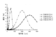
- the particle size distribution of the coolant sprayed from the spray nozzle used in each example and comparative example is shown in FIG.
- the average droplet diameter is shown in Table 1 below.
- Example 1 For each of Examples 1 to 3 and Comparative Example 1, the temperature of the reaction product gas immediately after the primary cooling in the quench pipe 106, the temperature of the gas extracted from the top of the trichlorosilane cooling tower 100, and included in the gas The content of the high boiling point polymer to be recovered and the recovered amount of trichlorosilane recovered from this gas via the condenser 300 were examined. The results are shown in Table 1 below.
Landscapes
- Chemical & Material Sciences (AREA)
- Organic Chemistry (AREA)
- Inorganic Chemistry (AREA)
- Engineering & Computer Science (AREA)
- Mechanical Engineering (AREA)
- General Engineering & Computer Science (AREA)
- Silicon Compounds (AREA)
Abstract
本発明は、反応生成ガスの冷却効率を大幅に改善できるトリクロロシラン冷却塔に関し、テトラクロロシランと水素とを含有する原料ガスを700~1400°Cの範囲の温度で反応させて得られるトリクロロシランを含有する反応生成ガスに平均液滴粒子径が2000μm以下の範囲の冷却液を噴霧して70~600°Cの温度範囲に急冷する一次冷却手段と、一次冷却手段の上方に設けられ、一次冷却後の反応生成ガスに冷却液をさらに噴霧して30~60°Cの温度範囲に冷却する二次冷却手段とを有する。
Description
本発明は、テトラクロロシランおよび水素からトリクロロシランを生産する際に使用されるトリクロロシラン冷却塔並びに当該トリクロロシラン冷却塔を用いたトリクロロシラン製造方法に関する。
トリクロロシラン(SiHCl3)は、半導体、液晶パネル、太陽電池等の製造に用いられる特殊材料ガスである。近年、需要は順調に拡大し、エレクトロニクス分野で広く使用されるCVD材料として、今後も伸びが期待されている。
トリクロロシランは、テトラクロロシラン(SiCl4)と水素(H2)とを接触させ、以下の熱平衡状態を達成することによって生成される。
SiCl4+H2⇔SiHCl3+HCl (1)
この反応は、ガス化したテトラクロロシランと水素からなる原料ガスを反応炉において700℃~1400℃に加熱することによって行われる。
SiCl4+H2⇔SiHCl3+HCl (1)
この反応は、ガス化したテトラクロロシランと水素からなる原料ガスを反応炉において700℃~1400℃に加熱することによって行われる。
反応炉から排出される高温の反応生成ガスには、生成されたトリクロロシランおよび塩化水素の他、多量の未反応テトラクロロシランおよび水素が含まれている。反応生成ガスからトリクロロシランを取り出すには、テトラクロロシランとトリクロロシランの沸点の相違を利用して蒸留塔で凝縮する方法が用いられる。具体的には、凝縮器で凝縮分であるクロロシランと、未凝縮分である塩化水素、水素、未凝縮クロロシランとに分け、さらに、凝縮分を深冷分離により-70℃程度まで冷却してトリクロロシランを分離する。
反応生成ガスから目的とするトリクロロシランを分離するにあたり、反応炉から導出されたばかりの高温の反応生成ガスをいきなり蒸留塔に導入してしまうと蒸留塔に過度の負荷がかかるため、典型的には、反応生成ガスを蒸留塔に導入する前に冷却塔において予備的に冷却しておく必要がある。
しかし、予備的冷却とはいっても、冷却力が不十分であると上記式(1)の平衡がテトラクロロシラン側に傾き、一旦は生成したトリクロロシランが再びテトラクロロシランへと戻ってしまう。そこで、トリクロロシランの回収効率の向上を図るために、平衡が十分にトリクロロシラン側に達した時点で反応生成ガスを可能な限り瞬時に所定温度まで冷却して平衡を凍結する必要がある。上記平衡状態を瞬時に凍結するには、典型的には、反応生成ガスを1秒未満のうちに600℃程度にまで急冷する必要がある。
テトラクロロシランと水素とを反応させてトリクロロシランに転換し、さらに反応生成ガスを冷却する工程を備えたトリクロロシラン製造方法としては、例えば、特許文献1に記載されたものがある。この文献に記載される方法は、テトラクロロシランと水素とを反応室内に導入し、800℃以上の温度で反応させてトリクロロシランと塩化水素とを含む混合ガスを生成する工程と、上記反応室から上記混合ガスを導出する際に、該混合ガスに水素、テトラクロロシラン、または塩化水素の少なくとも一種を主体とする冷却ガスを導入して該混合ガスを冷却する工程を有する。
この文献によれば、反応生成ガスを1秒以内の冷却速度で650℃以下の温度にまで急冷するとSi2Cl6、Si3Cl8、Si2H2Cl4等の高沸点ポリマーを副生しやすいこと、冷却ガスとして塩化水素を用いれば高沸点ポリマーを分解してトリクロロシランを生成することからトリクロロシランの転換率を向上できることが記載されている。さらに、塩化水素を主体とする冷却ガスを用いればSiCl2の副生を抑えられることが記載されている。
しかしながら、特許文献1に記載されている方法では、800℃以上に達している混合ガスの冷却が冷却ガスとの熱交換のみに委ねられているため、短時間で急激に冷却するには混合ガスに対して大量の冷却ガスを導入する必要があり、効率が悪く、冷却に要する負荷が高い。
また、テトラクロロシランおよび水素からトリクロロシランが生成する反応は吸熱反応であるため、ル・シャトリエの原理に従えば、単に冷却を行うだけでも、冷却による温度低下を相殺する方向、すなわちトリクロロシランと塩化水素からテトラクロロシランを生成する方向に平衡が傾いてしまう。それにも拘わらず、冷却ガスとして塩化水素を大量に導入してしまうと、反応系内のHCl濃度が上昇し、上記式(1)の平衡を一層左側へと推し戻してしまうことになる。従って、冷却ガスとして塩化水素を使用した場合には、高沸点ポリマーの副生は避けられるかもしれないが、結果的にトリクロロシランの回収効率が低下するおそれがある。
そこで、このようなガス冷却より強力かつ効率的に反応生成ガスを冷却する方法として、反応生成ガスを高温の反応炉から冷却塔へと導出し、そこで反応生成ガスに冷却液を直接噴霧し、冷却液が気化する際の蒸発潜熱を利用して反応生成ガスから熱を奪う方法が提案されている。
例えば特許文献2には、テトラクロロシランと水素を反応室に導入して600℃~1200℃の温度で転換反応させることによってトリクロロシランと塩化水素とを含む反応生成ガスを得た後、反応室から導出された反応生成ガスに室温に冷却されたクロロシラン混合物を噴霧し、1秒以内に300℃以下にまで急冷する冷却手段を備えた装置が提案されている。
ところで、特許文献2に記載の装置では、生成されたトリクロロシランは主に急冷室で凝縮されて、急冷室の下方に設けられた受容器に収集される。そのため、受容器にはトリクロロシランとともに、それよりも沸点の高い副生物、すなわちSi2Cl6、Si3Cl8、Si2H2Cl4等の高沸点ポリマーも回収されてしまい、回収したクロロシラン混合物から目的とするトリクロロシランのみを分溜する作業にかかる負荷が大きくなってしまう。
また、特許文献2には、反応によって得られた反応混合物(クロロシラン混合物)を室温に冷却し、これを冷却液として用いることが記載されているが、クロロシラン混合物からなる冷却液の噴霧条件について具体的な開示はない。
また、特許文献2には、反応によって得られた反応混合物(クロロシラン混合物)を室温に冷却し、これを冷却液として用いることが記載されているが、クロロシラン混合物からなる冷却液の噴霧条件について具体的な開示はない。
本発明は上記事情に鑑みてなされたものであり、既存設備の大幅な変更や冷却に要する負荷を増大することなく、トリクロロシランを含む反応生成ガスの冷却効率に優れ、しかも高沸点ポリマーの副生を問題としない、トリクロロシランの回収効率に優れたトリクロロシラン冷却塔およびそれを用いたトリクロロシラン製造方法を提供することを目的とする。
本発明は、前記課題を解決するために以下の構成を採用した。
すなわち、本発明のトリクロロシラン冷却塔は、
テトラクロロシランと水素とを含有する原料ガスを700~1400℃の範囲の温度で反応させて得られるトリクロロシランを含有する反応生成ガスに平均液滴粒子径が2000μm以下の範囲の冷却液を噴霧して70~600℃の温度範囲に急冷する一次冷却手段と、前記一次冷却手段の上方に設けられ、一次冷却後の反応生成ガスに冷却液をさらに噴霧して30~60℃の温度範囲に冷却する二次冷却手段と、
を有する。
すなわち、本発明のトリクロロシラン冷却塔は、
テトラクロロシランと水素とを含有する原料ガスを700~1400℃の範囲の温度で反応させて得られるトリクロロシランを含有する反応生成ガスに平均液滴粒子径が2000μm以下の範囲の冷却液を噴霧して70~600℃の温度範囲に急冷する一次冷却手段と、前記一次冷却手段の上方に設けられ、一次冷却後の反応生成ガスに冷却液をさらに噴霧して30~60℃の温度範囲に冷却する二次冷却手段と、
を有する。
また、本発明のトリクロロシラン製造方法は、
テトラクロロシランと水素とを含有する原料ガスを700~1400℃の範囲の温度で反応させて得られるトリクロロシランを含有する反応生成ガスを生成する工程と、
前記反応生成ガスに平均液滴粒子径が2000μm以下の範囲の冷却液を噴霧して1秒以内に70~600℃の範囲に急冷する一次冷却工程と、
前記一次冷却後の反応生成ガスに冷却液をさらに噴霧して30~60℃の範囲に冷却する二次冷却工程と、
を有する。
テトラクロロシランと水素とを含有する原料ガスを700~1400℃の範囲の温度で反応させて得られるトリクロロシランを含有する反応生成ガスを生成する工程と、
前記反応生成ガスに平均液滴粒子径が2000μm以下の範囲の冷却液を噴霧して1秒以内に70~600℃の範囲に急冷する一次冷却工程と、
前記一次冷却後の反応生成ガスに冷却液をさらに噴霧して30~60℃の範囲に冷却する二次冷却工程と、
を有する。
<冷却効率の改善>
本発明者等は、鋭意研究の結果、噴霧する冷却液の平均液滴粒子径が、従来よりも遙かに小さい範囲、特に2000μm以下の範囲であれば、反応生成ガスの冷却効率を大幅に改善できることを見出した。
本発明者等は、鋭意研究の結果、噴霧する冷却液の平均液滴粒子径が、従来よりも遙かに小さい範囲、特に2000μm以下の範囲であれば、反応生成ガスの冷却効率を大幅に改善できることを見出した。
これは、平均液滴粒子径が2000μm以下であると、冷却液の液滴が急冷管またはトリクロロシラン冷却塔内部の空間に漂う滞留時間を長く確保することができ反応生成ガスと十分に接触できること、さらには、液滴が小さく蒸発しやすいため蒸発潜熱の利用効率が優れていることが考えられる。
<高沸点ポリマーの除去>
また、急冷効率が高くなると一般に高沸点ポリマーが副生しやすくなるが、反応生成ガスをトリクロロシラン冷却塔において30~60℃の範囲まで二次冷却し、二次冷却後もなおガス状である物質のみをトリクロロシラン冷却塔の塔頂部から取り出し、冷却によって凝縮された液状物質については噴霧後の冷却液と共にトリクロロシラン冷却塔の底部から回収することにより、前記温度帯域でガス状であるトリクロロシランと、当該温度帯域で凝縮してしまう高沸点ポリマーとを別個に取り出すことができる。そのため、高沸点ポリマーの副生を気にすることなく反応生成ガスを瞬時に冷却することができ、より確実に平衡を凍結することができる。これにより、一度生成したトリクロロシランの損失を抑えることができる。さらに、高沸点ポリマーとトリクロロシランとの分溜にかかっていた負荷を大幅に軽減することができる。
また、急冷効率が高くなると一般に高沸点ポリマーが副生しやすくなるが、反応生成ガスをトリクロロシラン冷却塔において30~60℃の範囲まで二次冷却し、二次冷却後もなおガス状である物質のみをトリクロロシラン冷却塔の塔頂部から取り出し、冷却によって凝縮された液状物質については噴霧後の冷却液と共にトリクロロシラン冷却塔の底部から回収することにより、前記温度帯域でガス状であるトリクロロシランと、当該温度帯域で凝縮してしまう高沸点ポリマーとを別個に取り出すことができる。そのため、高沸点ポリマーの副生を気にすることなく反応生成ガスを瞬時に冷却することができ、より確実に平衡を凍結することができる。これにより、一度生成したトリクロロシランの損失を抑えることができる。さらに、高沸点ポリマーとトリクロロシランとの分溜にかかっていた負荷を大幅に軽減することができる。
<回収効率の向上>
また特に、反応生成ガスをあまりに冷却し過ぎると一部のトリクロロシランが凝縮に至るおそれがあるが、冷却手段を多段的に設け、一次冷却工程では平衡を凍結するのに十分な温度70~600℃まで瞬時に急冷し、二次冷却工程では専ら高沸点ポリマーを凝縮させるべく30~60℃の範囲まで穏やかに冷却することにより、トリクロロシランをガス状のまま効率よく回収することができる。
また特に、反応生成ガスをあまりに冷却し過ぎると一部のトリクロロシランが凝縮に至るおそれがあるが、冷却手段を多段的に設け、一次冷却工程では平衡を凍結するのに十分な温度70~600℃まで瞬時に急冷し、二次冷却工程では専ら高沸点ポリマーを凝縮させるべく30~60℃の範囲まで穏やかに冷却することにより、トリクロロシランをガス状のまま効率よく回収することができる。
本発明に係るトリクロロシラン冷却塔およびそれを用いたトリクロロシラン製造方法によれば、反応生成ガスの冷却効率が極めて優れているため、トリクロロシランに傾いた平衡状態を瞬時により確実に凍結することができる。また、トリクロロシランと高沸点ポリマーとを分離して取り出すことができるため、トリクロロシランの分溜負荷を低減することができる。さらに、冷却手段を多段的に設けることで、より多くのトリクロロシランをガス状のまま取り出すことができる。かくして、これらが相乗的に作用することにより、トリクロロシランの生産性を大幅に改善することができる。
100 トリクロロシラン冷却塔
101 金属製容器
102 一次スプレーノズル
103 二次スプレーノズル
104 一次冷却液供給管
105 二次冷却液供給管
106 急冷管
107 充填部材
108 反応生成ガス導入開口部
109 冷却塔ガス成分抜出管
110 冷却塔液体成分抜出管
111 導入開口部
112 排出開口部
200 原料ガス供給管
201 反応炉
202 ヒータ
203 反応炉ガス抜出管
300 凝縮器
301 貯槽
400 貯槽
401 調製液供給管
402 ポンプ
403 熱交換器
101 金属製容器
102 一次スプレーノズル
103 二次スプレーノズル
104 一次冷却液供給管
105 二次冷却液供給管
106 急冷管
107 充填部材
108 反応生成ガス導入開口部
109 冷却塔ガス成分抜出管
110 冷却塔液体成分抜出管
111 導入開口部
112 排出開口部
200 原料ガス供給管
201 反応炉
202 ヒータ
203 反応炉ガス抜出管
300 凝縮器
301 貯槽
400 貯槽
401 調製液供給管
402 ポンプ
403 熱交換器
以下、本発明の実施の形態について、図面を用いて説明する。
1.トリクロロシラン冷却塔
図1は、本実施形態のトリクロロシラン冷却塔とそれを用いたトリクロロシラン製造方法を実施するための装置を概略的に示したものである。
本実施形態のトリクロロシラン冷却塔100は、略円筒状の金属製容器101と、当該容器内に設置され容器内に冷却液を噴霧する一次スプレーノズル102および二次スプレーノズル103と、当該一次スプレーノズル102および二次スプレーノズル103にそれぞれ接続されこれらに冷却液を供給する一次冷却液供給管104および二次冷却液供給管105と、前記金属製容器101内部において前記一次スプレーノズル102と接続された急冷管106と、前記一次スプレーノズル102と二次スプレーノズル103との間に設置された充填部材107とを備える。
1.トリクロロシラン冷却塔
図1は、本実施形態のトリクロロシラン冷却塔とそれを用いたトリクロロシラン製造方法を実施するための装置を概略的に示したものである。
本実施形態のトリクロロシラン冷却塔100は、略円筒状の金属製容器101と、当該容器内に設置され容器内に冷却液を噴霧する一次スプレーノズル102および二次スプレーノズル103と、当該一次スプレーノズル102および二次スプレーノズル103にそれぞれ接続されこれらに冷却液を供給する一次冷却液供給管104および二次冷却液供給管105と、前記金属製容器101内部において前記一次スプレーノズル102と接続された急冷管106と、前記一次スプレーノズル102と二次スプレーノズル103との間に設置された充填部材107とを備える。
<金属製容器>
金属製容器101は反応生成ガスと反応しない材質であれば特に限定されず、典型的にはステンレス等の金属から構成することができる。金属製容器101の側壁には、反応生成ガスを取り込むための反応生成ガス導入開口部108が設けられている。金属製容器101の上部には、冷却された反応生成ガスのガス成分を取り出すための冷却塔ガス成分抜出管109が接続されており、金属製容器101の底部には、冷却に用いられた冷却液および冷却により生じた凝縮分を抜き取るための冷却塔液体成分抜出管110が接続されている。
金属製容器101は反応生成ガスと反応しない材質であれば特に限定されず、典型的にはステンレス等の金属から構成することができる。金属製容器101の側壁には、反応生成ガスを取り込むための反応生成ガス導入開口部108が設けられている。金属製容器101の上部には、冷却された反応生成ガスのガス成分を取り出すための冷却塔ガス成分抜出管109が接続されており、金属製容器101の底部には、冷却に用いられた冷却液および冷却により生じた凝縮分を抜き取るための冷却塔液体成分抜出管110が接続されている。
<急冷管>
急冷管106は反応生成ガスと反応しない材質であれば特に限定されず、典型的にはステンレス等の金属から構成することができる。
急冷管106には、前記金属製容器101の反応生成ガス導入開口部108と対応する位置に、反応生成ガスを取り込むための導入開口部111が設けられている。また、急冷管106の底部は全面開放されており、冷却された反応生成ガスを排出するための排出開口部112を形成している。
急冷管106は反応生成ガスと反応しない材質であれば特に限定されず、典型的にはステンレス等の金属から構成することができる。
急冷管106には、前記金属製容器101の反応生成ガス導入開口部108と対応する位置に、反応生成ガスを取り込むための導入開口部111が設けられている。また、急冷管106の底部は全面開放されており、冷却された反応生成ガスを排出するための排出開口部112を形成している。
<一次スプレーノズル>
一次スプレーノズル102は、前記急冷管106の天蓋部から急冷管106の内部に向けて設置され、一次冷却液供給管104と接続されている。一次スプレーノズル102は、急冷管106の導入開口部111から導入される反応生成ガスに向けて冷却液を噴霧することにより、上記式(1)の平衡が凍結する70~600℃まで瞬間的に急冷する。
一次スプレーノズル102は、2000μm以下の範囲の平均液滴粒子径の液滴を噴霧できるものであれば特に限定されず、種々のタイプのノズルを用いることができる。特に、噴霧領域全体にわたって均等な流量分布を実現できる充円錐ノズルが好ましい。平均液滴粒子径はノズルの特性のみならず噴霧条件によっても左右されるが、本実施形態では、噴霧量が0.1~0.3l/min、噴霧圧力が0.1~0.2MPa、冷却液として後述する混合比のテトラクロロシランとトリクロロシランとからなる混合液を用いた場合に、上記平均液滴粒子径を実現できるものを用いる。
一次スプレーノズル102は、前記急冷管106の天蓋部から急冷管106の内部に向けて設置され、一次冷却液供給管104と接続されている。一次スプレーノズル102は、急冷管106の導入開口部111から導入される反応生成ガスに向けて冷却液を噴霧することにより、上記式(1)の平衡が凍結する70~600℃まで瞬間的に急冷する。
一次スプレーノズル102は、2000μm以下の範囲の平均液滴粒子径の液滴を噴霧できるものであれば特に限定されず、種々のタイプのノズルを用いることができる。特に、噴霧領域全体にわたって均等な流量分布を実現できる充円錐ノズルが好ましい。平均液滴粒子径はノズルの特性のみならず噴霧条件によっても左右されるが、本実施形態では、噴霧量が0.1~0.3l/min、噴霧圧力が0.1~0.2MPa、冷却液として後述する混合比のテトラクロロシランとトリクロロシランとからなる混合液を用いた場合に、上記平均液滴粒子径を実現できるものを用いる。
<平均液滴粒子径>
ここで用いる平均液滴粒子径とは、液浸法又はレーザー法により、ni[個]の粒子径Di[μm]を測定し、次式のザウター平均粒子径により求められる値とする。
平均粒子径=Σni・Di3/Σni・Di2
(niは粒子径Diを有する冷却液の噴霧液滴の個数)
ここで用いる平均液滴粒子径とは、液浸法又はレーザー法により、ni[個]の粒子径Di[μm]を測定し、次式のザウター平均粒子径により求められる値とする。
平均粒子径=Σni・Di3/Σni・Di2
(niは粒子径Diを有する冷却液の噴霧液滴の個数)
<充填部材>
充填部材107は、前記一次スプレーノズル102の上方に設置される。充填部材107は、急冷管106において一次冷却されて急冷管106の排出開口部112から押し出された反応生成ガスがトリクロロシラン冷却塔100の内部を上昇する際にその直進を乱すようにガス通路を形成するものであればどのような形態をとってもよい。例えばチップ状またはブロック状等の小塊状部材を不規則に詰め込んだ形態や、多数の孔を設けた複数の板状部材を間隔をあけて並べた形態とすることができる。
充填部材107は反応生成ガスと反応しない材質であれば特に限定されず、典型的にはステンレス等の金属から構成することができる。
充填部材107は、前記一次スプレーノズル102の上方に設置される。充填部材107は、急冷管106において一次冷却されて急冷管106の排出開口部112から押し出された反応生成ガスがトリクロロシラン冷却塔100の内部を上昇する際にその直進を乱すようにガス通路を形成するものであればどのような形態をとってもよい。例えばチップ状またはブロック状等の小塊状部材を不規則に詰め込んだ形態や、多数の孔を設けた複数の板状部材を間隔をあけて並べた形態とすることができる。
充填部材107は反応生成ガスと反応しない材質であれば特に限定されず、典型的にはステンレス等の金属から構成することができる。
<二次スプレーノズル>
二次スプレーノズル103は、前記一次スプレーノズル102および充填部材107のさらに上方に設置され、二次冷却液供給管105と接続されている。二次スプレーノズル103は、急冷管106の排出開口部112から押し出されトリクロロシラン冷却塔100の内部を上昇し充填部材107をすり抜けてくる反応生成ガスに向けて冷却液を噴霧することにより、高沸点ポリマーを凝縮させつつ、反応生成ガスの温度を30~60℃の範囲まで穏やかに冷却する。また、二次スプレーノズル103から噴霧される冷却液は、トリクロロシラン冷却塔100内部全体の温度を下げ、冷却液が反応生成ガスと接触する前に気化してしまうことを抑制する働きも有する。
二次スプレーノズル103は、特に限定されず、種々のタイプのノズルを用いることができる。特に、噴霧領域全体にわたって均等な流量分布を実現できる充円錐ノズルが好ましい。二次スプレーノズル103から噴霧される冷却液の平均液滴粒子径は特に限定されないが、上記一次スプレーノズル102と同様に2000μm以下の範囲であれば冷却効率に優れるため好ましい。
二次スプレーノズル103は、前記一次スプレーノズル102および充填部材107のさらに上方に設置され、二次冷却液供給管105と接続されている。二次スプレーノズル103は、急冷管106の排出開口部112から押し出されトリクロロシラン冷却塔100の内部を上昇し充填部材107をすり抜けてくる反応生成ガスに向けて冷却液を噴霧することにより、高沸点ポリマーを凝縮させつつ、反応生成ガスの温度を30~60℃の範囲まで穏やかに冷却する。また、二次スプレーノズル103から噴霧される冷却液は、トリクロロシラン冷却塔100内部全体の温度を下げ、冷却液が反応生成ガスと接触する前に気化してしまうことを抑制する働きも有する。
二次スプレーノズル103は、特に限定されず、種々のタイプのノズルを用いることができる。特に、噴霧領域全体にわたって均等な流量分布を実現できる充円錐ノズルが好ましい。二次スプレーノズル103から噴霧される冷却液の平均液滴粒子径は特に限定されないが、上記一次スプレーノズル102と同様に2000μm以下の範囲であれば冷却効率に優れるため好ましい。
<冷却液>
冷却液は、テトラクロロシランとトリクロロシランとからなる混合液を用いることが好ましく、混合液中のテトラクロロシランの含有量は好ましくは80~100モル%、より好ましくは85~95モル%である。かかる特定の組成の冷却液を用いることにより、上記式(1)の平衡が十分に右側に移動した状態を保ったまま反応を凍結でき、高い収率でトリクロロシランを回収することができる。
冷却液は、50℃以下に温度調整されていることが好ましい。冷却液が、50℃以下に温度調整されていれば、短時間で反応生成ガスの温度を急冷することができるため、上記の式(1)で十分に右側に移動した状態が保たれたまま平衡を凍結できる。
冷却液は、テトラクロロシランとトリクロロシランとからなる混合液を用いることが好ましく、混合液中のテトラクロロシランの含有量は好ましくは80~100モル%、より好ましくは85~95モル%である。かかる特定の組成の冷却液を用いることにより、上記式(1)の平衡が十分に右側に移動した状態を保ったまま反応を凍結でき、高い収率でトリクロロシランを回収することができる。
冷却液は、50℃以下に温度調整されていることが好ましい。冷却液が、50℃以下に温度調整されていれば、短時間で反応生成ガスの温度を急冷することができるため、上記の式(1)で十分に右側に移動した状態が保たれたまま平衡を凍結できる。
2.トリクロロシラン製造方法
次に、上記トリクロロシラン冷却塔を用いてトリクロロシランを製造する方法について、図1を用いて説明する。
まず、ガス化したテトラクロロシランと水素とを混合した原料ガスを原料ガス供給管200を通じて反応炉201の底部に供給する。
次に、上記トリクロロシラン冷却塔を用いてトリクロロシランを製造する方法について、図1を用いて説明する。
まず、ガス化したテトラクロロシランと水素とを混合した原料ガスを原料ガス供給管200を通じて反応炉201の底部に供給する。
反応炉201は黒鉛製であり、周囲に設けられた最大出力500KWのヒータ202にて加熱することで、反応炉201の内部を700℃を超え1400℃以下の範囲内の状態に保つことができる。反応温度が700℃以上であれば上記式(1)の平衡が十分に右側に傾くため好ましく、1400℃以下であれば金属シリコンが析出して装置の閉塞に繋がる現象を抑制できるため好ましい。
反応炉201内で加熱され、上記式(1)に示す熱平衡状態に達した反応生成ガスは、反応炉201の上方へ移動し、700℃以上の温度を保った状態で反応炉ガス抜出管203を通じてトリクロロシラン冷却塔100に導入される。
反応炉ガス抜出管203はトリクロロシラン冷却塔100の側壁および急冷管106の側壁を貫通して、急冷管106の内部に達している。急冷管106の内部に取り出された反応生成ガスに対し、一次冷却液供給管104に接続された一次スプレーノズル102から平均液滴粒子径が2000μm以下の範囲である冷却液を噴霧して、平衡が凍結する70~600℃の範囲まで瞬間的に急冷する。このとき、狭い急冷管106内で反応生成ガスと微細液滴状の冷却液とが混合されることにより両者がより確実に接触し、冷却液が気化する際の蒸発潜熱を利用して反応生成ガスから瞬時に効率よく熱が奪われる。これによって反応生成ガス内の物質間平衡状態が凍結される。
次いで、急冷管106内で急冷された反応生成ガスは、急冷管106の排出開口部112から押し出されてトリクロロシラン冷却塔100内部を上昇し、充填部材107をすり抜ける。ここで、二次冷却液供給管105に接続された二次スプレーノズル103から冷却液をさらに噴霧して、反応生成ガス中の高沸点ポリマーを凝縮させつつ、反応生成ガスの温度を30~60℃の範囲まで穏やかに冷却する。ここで、上記一次冷却によって反応生成ガスの温度が70~600℃に急冷された時点でほぼ熱平衡状態は凍結されるため、二次冷却によりそれ以下の温度に冷却しても、一次冷却後の反応生成ガスと組成においては殆ど変わらない。そのため、二次冷却は、短時間で急激に冷却する必要はなく、むしろトリクロロシランを凝縮させずに高沸点ポリマーのみを凝縮させるべく、より穏やかな条件で冷却することが好ましい。
30~60℃の範囲に冷却してもなお気体のままであるガス成分は、冷却塔ガス成分抜出管109より抜き出され、凝縮器300で冷却され、ここでガス中のクロロシランの大部分が凝縮されて貯槽301に捕集される。一方、30~60℃の温度帯域で凝縮してしまう高沸点ポリマー等の凝縮分は、冷却液と共にトリクロロシラン冷却塔100の底部へと流下し、冷却塔液体成分抜出管110から抜き出される。
冷却に用いられた冷却液および冷却により凝縮した凝縮分は、冷却塔液体成分抜出管110を介して貯槽400に捕集される。さらに貯槽400には、冷却液のテトラクロロシランの濃度を一定に保つため、テトラクロロシラン及び/またはトリクロロシランからなる調製液が調製液供給管401を通じて供給される。
貯槽400内で調製された冷却液はポンプ402により抜き取られ、熱交換器403により冷却され、一次冷却液供給管104並びに二次冷却液供給管105を通じて再びトリクロロシラン冷却塔100に供給される。なお、熱交換器403はジャケットに冷却水を通じて冷却できるようになっている。
なお、本発明の技術範囲は上記実施形態に限定されるものではなく、本発明の趣旨を逸脱しない範囲において種々の変更を加えることが可能である。
例えば、上記実施態様では、反応生成ガスの冷却方式として二つの噴霧手段からなる2段階冷却方式を用いたが、一次冷却によって反応生成ガスの温度を500~600℃に急冷してしまえば、その後の反応生成ガスの組成はほぼ変わらないため、二次冷却を複数の噴霧手段を用いてより多段階的に行うこともできる。
<実施例1~3および比較例1>
実施例1~3および比較例1のいずれも、図1に示す装置を用いて実験した。反応炉201は内径50mm、長さ800mmで、ヒータ202により加熱されるようになっており、反応炉201の中心部が温度1300℃となるように加熱した。金属製容器101は、内径140mm、長さ1300mmで、内側に内径35mm、長さ420mmで底部が開放された急冷管106を設置した。
実施例1~3および比較例1のいずれも、図1に示す装置を用いて実験した。反応炉201は内径50mm、長さ800mmで、ヒータ202により加熱されるようになっており、反応炉201の中心部が温度1300℃となるように加熱した。金属製容器101は、内径140mm、長さ1300mmで、内側に内径35mm、長さ420mmで底部が開放された急冷管106を設置した。
予め600℃に加熱したテトラクロロシランと水素とからなる原料ガスを27モル/時間の流量で原料ガス供給管200を通じて反応炉201に連続的に供給し、さらに反応炉201において反応したガスを反応炉ガス抜出管203を通じて金属製容器101内部に設置された急冷管106に供給した。原料のテトラクロロシランはテトラクロロシランと水素の合計に対して33モル%とした。
一方、予め貯槽400にトリクロロシランとテトラクロロシランの混合物(モル比=85:15)からなる冷却液を13モル充填しておき、熱交換器403を20℃の冷却水で冷却し、ポンプ402を駆動して、貯槽400の冷却液を一次スプレーノズル102および二次スプレーノズル103を介してそれぞれ急冷管106内と金属製容器101内に連続的に噴霧した。
ここで、実施例1~3および比較例1のいずれの場合も、一次スプレーノズル102を介して供給される冷却液は、噴霧量が0.1l/min、噴霧圧力が0.15MPaとし、二次スプレーノズル103を介して供給される冷却液は、噴霧量が0.6l/min、噴霧圧力が0.15MPaの噴霧条件とした。
また、冷却液の温度は、熱交換器403を通過させることにより30℃に保った。金属製容器101の塔底より抜き出される冷却液は貯槽400に回収して、連続的に用いた。必要に応じて、冷却液に、調製液供給管401を通じて連続的にテトラクロロシランあるいはトリクロロシランを補充し、組成を一定に保った。
また、冷却液の温度は、熱交換器403を通過させることにより30℃に保った。金属製容器101の塔底より抜き出される冷却液は貯槽400に回収して、連続的に用いた。必要に応じて、冷却液に、調製液供給管401を通じて連続的にテトラクロロシランあるいはトリクロロシランを補充し、組成を一定に保った。
上記各実施例および比較例毎に、同一のタイプのスプレーノズルを一次スプレーノズル102および二次スプレーノズル103としてそれぞれ使用した。すなわち、各実施例および比較例毎に、 一次スプレーノズル102および二次スプレーノズル103から噴霧される冷却液は同一の粒径分布となるようにした。
各実施例および比較例で使用したスプレーノズルから噴霧される冷却液の粒径分布を図2に示す。また、平均液滴粒子径を以下の表1に示す。
各実施例および比較例で使用したスプレーノズルから噴霧される冷却液の粒径分布を図2に示す。また、平均液滴粒子径を以下の表1に示す。
実施例1~3および比較例1のそれぞれについて、急冷管106において一次冷却された直後の反応生成ガスの温度、トリクロロシラン冷却塔100の塔頂より抜き出されたガスの温度、ガス中に含まれる高沸点ポリマーの含有量、並びに、このガスから凝縮器300を介して回収されたトリクロロシランの回収量を調べた。結果を以下の表1に示す。

<結果の考察>
上記の実施例1~3および比較例1の実験結果から、平均液滴粒子径が2000μm以下の範囲である冷却液を噴霧することにより、トリクロロシランの回収効率を著しく向上することができた。また、実施例1~3のいずれの場合も、トリクロロシラン冷却塔から取り出される反応生成ガス中に高沸点ポリマーが殆ど含まれていないことが示された。
上記の実施例1~3および比較例1の実験結果から、平均液滴粒子径が2000μm以下の範囲である冷却液を噴霧することにより、トリクロロシランの回収効率を著しく向上することができた。また、実施例1~3のいずれの場合も、トリクロロシラン冷却塔から取り出される反応生成ガス中に高沸点ポリマーが殆ど含まれていないことが示された。
以上、本発明を実施例に基づいて説明した。この実施例はあくまで例示であり、種々の変形例が可能なこと、またそうした変形例も本発明の範囲にあることは当業者に理解されるところである。
Claims (6)
- テトラクロロシランと水素とを含有する原料ガスを700~1400℃の範囲の温度で反応させて得られるトリクロロシランを含有する反応生成ガスに平均液滴粒子径が2000μm以下の範囲の冷却液を噴霧して70~600℃の温度範囲に急冷する一次冷却手段と、
一次冷却手段の上方に設けられ、一次冷却後の反応生成ガスに冷却液をさらに噴霧して30~60℃の温度範囲に冷却する二次冷却手段と、
を有するトリクロロシラン冷却塔。 - 反応生成ガスを導入するための導入開口部および当該反応生成ガスを排出するための排出開口部が配設された略円筒状の急冷管を内部に有し、当該急冷管に一次冷却手段が接続され当該急冷管の内部において一次冷却手段から噴霧される冷却液と反応生成ガスとが混合される請求項1記載のトリクロロシラン冷却塔。
- 一次冷却手段と二次冷却手段との間に反応生成ガスの流れを乱す充填部材を有する請求項1記載のトリクロロシラン冷却塔。
- 二次冷却手段により噴霧される冷却液の平均液滴粒子径が2000μm以下の範囲である請求項1記載のトリクロロシラン冷却塔。
- 冷却液が、テトラクロロシランおよびトリクロロシランを含有し、当該テトラクロロシランおよびトリクロロシランの合計質量を100モル%とした場合に、テトラクロロシランを80モル%以上の含有率で含む請求項1記載のトリクロロシラン冷却塔。
- テトラクロロシランと水素とを含有する原料ガスを700~1400℃の範囲の温度で反応させて得られるトリクロロシランを含有する反応生成ガスを生成する工程と、
反応生成ガスに平均液滴粒子径が2000μm以下の範囲の冷却液を噴霧して1秒以内に70~600℃の範囲に急冷する一次冷却工程と、
一次冷却後の反応生成ガスに冷却液をさらに噴霧して30~60℃の範囲に冷却する二次冷却工程と、
を有するトリクロロシラン製造方法。
Priority Applications (3)
| Application Number | Priority Date | Filing Date | Title |
|---|---|---|---|
| PCT/JP2009/054271 WO2010100750A1 (ja) | 2009-03-06 | 2009-03-06 | トリクロロシラン冷却塔およびそれを用いたトリクロロシラン製造方法 |
| JP2011502552A JP5374576B2 (ja) | 2009-03-06 | 2009-03-06 | トリクロロシラン冷却塔およびそれを用いたトリクロロシラン製造方法 |
| TW099102350A TW201034957A (en) | 2009-03-06 | 2010-01-28 | Cooling tower of trichlorosilane and preparation method of trichlorosilane using the same |
Applications Claiming Priority (1)
| Application Number | Priority Date | Filing Date | Title |
|---|---|---|---|
| PCT/JP2009/054271 WO2010100750A1 (ja) | 2009-03-06 | 2009-03-06 | トリクロロシラン冷却塔およびそれを用いたトリクロロシラン製造方法 |
Publications (1)
| Publication Number | Publication Date |
|---|---|
| WO2010100750A1 true WO2010100750A1 (ja) | 2010-09-10 |
Family
ID=42709328
Family Applications (1)
| Application Number | Title | Priority Date | Filing Date |
|---|---|---|---|
| PCT/JP2009/054271 Ceased WO2010100750A1 (ja) | 2009-03-06 | 2009-03-06 | トリクロロシラン冷却塔およびそれを用いたトリクロロシラン製造方法 |
Country Status (3)
| Country | Link |
|---|---|
| JP (1) | JP5374576B2 (ja) |
| TW (1) | TW201034957A (ja) |
| WO (1) | WO2010100750A1 (ja) |
Cited By (3)
| Publication number | Priority date | Publication date | Assignee | Title |
|---|---|---|---|---|
| JP2010235439A (ja) * | 2009-03-11 | 2010-10-21 | Mitsubishi Materials Corp | トリクロロシランの製造装置および製造方法 |
| JP2015042600A (ja) * | 2013-08-26 | 2015-03-05 | 三菱マテリアル株式会社 | トリクロロシラン製造方法 |
| JP2016064951A (ja) * | 2014-09-25 | 2016-04-28 | デンカ株式会社 | オクタクロロトリシランの製造方法並びに該方法により製造されるオクタクロロトリシラン |
Citations (6)
| Publication number | Priority date | Publication date | Assignee | Title |
|---|---|---|---|---|
| JPS4895396A (ja) * | 1972-02-26 | 1973-12-07 | ||
| JPS6081010A (ja) * | 1983-10-13 | 1985-05-09 | Denki Kagaku Kogyo Kk | トリクロルシランの製造法 |
| JPS6163519A (ja) * | 1984-09-04 | 1986-04-01 | Denki Kagaku Kogyo Kk | モノシラン製造法 |
| JP2008137885A (ja) * | 2006-11-07 | 2008-06-19 | Mitsubishi Materials Corp | トリクロロシランの製造方法およびトリクロロシラン製造装置 |
| JP2008143775A (ja) * | 2006-11-14 | 2008-06-26 | Mitsubishi Materials Corp | 水素分離回収方法および水素分離回収設備 |
| JP2009007240A (ja) * | 2007-05-25 | 2009-01-15 | Mitsubishi Materials Corp | トリクロロシランの製造方法と製造装置および多結晶シリコンの製造方法 |
-
2009
- 2009-03-06 JP JP2011502552A patent/JP5374576B2/ja active Active
- 2009-03-06 WO PCT/JP2009/054271 patent/WO2010100750A1/ja not_active Ceased
-
2010
- 2010-01-28 TW TW099102350A patent/TW201034957A/zh unknown
Patent Citations (6)
| Publication number | Priority date | Publication date | Assignee | Title |
|---|---|---|---|---|
| JPS4895396A (ja) * | 1972-02-26 | 1973-12-07 | ||
| JPS6081010A (ja) * | 1983-10-13 | 1985-05-09 | Denki Kagaku Kogyo Kk | トリクロルシランの製造法 |
| JPS6163519A (ja) * | 1984-09-04 | 1986-04-01 | Denki Kagaku Kogyo Kk | モノシラン製造法 |
| JP2008137885A (ja) * | 2006-11-07 | 2008-06-19 | Mitsubishi Materials Corp | トリクロロシランの製造方法およびトリクロロシラン製造装置 |
| JP2008143775A (ja) * | 2006-11-14 | 2008-06-26 | Mitsubishi Materials Corp | 水素分離回収方法および水素分離回収設備 |
| JP2009007240A (ja) * | 2007-05-25 | 2009-01-15 | Mitsubishi Materials Corp | トリクロロシランの製造方法と製造装置および多結晶シリコンの製造方法 |
Cited By (3)
| Publication number | Priority date | Publication date | Assignee | Title |
|---|---|---|---|---|
| JP2010235439A (ja) * | 2009-03-11 | 2010-10-21 | Mitsubishi Materials Corp | トリクロロシランの製造装置および製造方法 |
| JP2015042600A (ja) * | 2013-08-26 | 2015-03-05 | 三菱マテリアル株式会社 | トリクロロシラン製造方法 |
| JP2016064951A (ja) * | 2014-09-25 | 2016-04-28 | デンカ株式会社 | オクタクロロトリシランの製造方法並びに該方法により製造されるオクタクロロトリシラン |
Also Published As
| Publication number | Publication date |
|---|---|
| JPWO2010100750A1 (ja) | 2012-09-06 |
| TW201034957A (en) | 2010-10-01 |
| JP5374576B2 (ja) | 2013-12-25 |
Similar Documents
| Publication | Publication Date | Title |
|---|---|---|
| KR101602006B1 (ko) | 헥사클로로디실란의 회수 방법 및 그 방법을 위한 플랜트 | |
| JP4620694B2 (ja) | 高純度トリクロロシランの製造方法 | |
| KR101292545B1 (ko) | 트리클로로실란의 정제 방법 및 정제 장치 | |
| CN102530953A (zh) | 完全利用供料气和全再循环cvd-西门子甲硅烷反应器法 | |
| TW201030192A (en) | Process for producing polycrystalline silicon | |
| CN101844769B (zh) | 三氯硅烷的制造装置和制造方法 | |
| JP5374576B2 (ja) | トリクロロシラン冷却塔およびそれを用いたトリクロロシラン製造方法 | |
| JP5329641B2 (ja) | クロロシラン回収装置およびそれを用いたクロロシラン回収方法 | |
| JP5826854B2 (ja) | シランを精製する方法及びシステム | |
| KR20160034908A (ko) | 이소시아네이트의 제조 방법 | |
| WO2010116500A1 (ja) | トリクロロシラン冷却塔およびそれを用いたトリクロロシラン製造方法 | |
| JP2016064951A (ja) | オクタクロロトリシランの製造方法並びに該方法により製造されるオクタクロロトリシラン | |
| US4324932A (en) | Process for the manufacture of vinyl chloride by the thermal cracking of 1,2-dichloroethane | |
| CN113387978B (zh) | 一种连续醇解法制备二苯基二甲氧基硅烷的方法 | |
| JP6486049B2 (ja) | ペンタクロロジシランの製造方法並びに該方法により製造されるペンタクロロジシラン | |
| TW201210940A (en) | Process for separating monosilane from chlorosilanes-rich mixture | |
| CN116425202B (zh) | 一种六氟化钨气体的制备方法 | |
| JP6391390B2 (ja) | ヘキサクロロジシランの製造方法 | |
| JP6283482B2 (ja) | トリクロロシラン製造方法 | |
| RU2608523C1 (ru) | Способ получения силана и хлорсиланов | |
| CN117339486A (zh) | 固定床制备及提纯硅烷的节能型装置及方法 | |
| RU2286378C1 (ru) | Способ охлаждения пирогаза |
Legal Events
| Date | Code | Title | Description |
|---|---|---|---|
| 121 | Ep: the epo has been informed by wipo that ep was designated in this application |
Ref document number: 09841113 Country of ref document: EP Kind code of ref document: A1 |
|
| WWE | Wipo information: entry into national phase |
Ref document number: 2011502552 Country of ref document: JP |
|
| NENP | Non-entry into the national phase |
Ref country code: DE |
|
| 122 | Ep: pct application non-entry in european phase |
Ref document number: 09841113 Country of ref document: EP Kind code of ref document: A1 |