WO2010098388A1 - 顎運動測定システム - Google Patents
顎運動測定システム Download PDFInfo
- Publication number
- WO2010098388A1 WO2010098388A1 PCT/JP2010/052974 JP2010052974W WO2010098388A1 WO 2010098388 A1 WO2010098388 A1 WO 2010098388A1 JP 2010052974 W JP2010052974 W JP 2010052974W WO 2010098388 A1 WO2010098388 A1 WO 2010098388A1
- Authority
- WO
- WIPO (PCT)
- Prior art keywords
- acceleration
- acceleration sensor
- jaw
- axis direction
- jaw movement
- Prior art date
Links
Images


Classifications
-
- A—HUMAN NECESSITIES
- A61—MEDICAL OR VETERINARY SCIENCE; HYGIENE
- A61B—DIAGNOSIS; SURGERY; IDENTIFICATION
- A61B5/00—Measuring for diagnostic purposes; Identification of persons
- A61B5/68—Arrangements of detecting, measuring or recording means, e.g. sensors, in relation to patient
- A61B5/6801—Arrangements of detecting, measuring or recording means, e.g. sensors, in relation to patient specially adapted to be attached to or worn on the body surface
- A61B5/6813—Specially adapted to be attached to a specific body part
- A61B5/6814—Head
- A61B5/682—Mouth, e.g., oral cavity; tongue; Lips; Teeth
-
- A—HUMAN NECESSITIES
- A61—MEDICAL OR VETERINARY SCIENCE; HYGIENE
- A61B—DIAGNOSIS; SURGERY; IDENTIFICATION
- A61B5/00—Measuring for diagnostic purposes; Identification of persons
- A61B5/103—Detecting, measuring or recording devices for testing the shape, pattern, colour, size or movement of the body or parts thereof, for diagnostic purposes
- A61B5/11—Measuring movement of the entire body or parts thereof, e.g. head or hand tremor, mobility of a limb
-
- A—HUMAN NECESSITIES
- A61—MEDICAL OR VETERINARY SCIENCE; HYGIENE
- A61B—DIAGNOSIS; SURGERY; IDENTIFICATION
- A61B5/00—Measuring for diagnostic purposes; Identification of persons
- A61B5/45—For evaluating or diagnosing the musculoskeletal system or teeth
- A61B5/4538—Evaluating a particular part of the muscoloskeletal system or a particular medical condition
- A61B5/4542—Evaluating the mouth, e.g. the jaw
- A61B5/4557—Evaluating bruxism
-
- A—HUMAN NECESSITIES
- A61—MEDICAL OR VETERINARY SCIENCE; HYGIENE
- A61B—DIAGNOSIS; SURGERY; IDENTIFICATION
- A61B2562/00—Details of sensors; Constructional details of sensor housings or probes; Accessories for sensors
- A61B2562/02—Details of sensors specially adapted for in-vivo measurements
- A61B2562/0219—Inertial sensors, e.g. accelerometers, gyroscopes, tilt switches
-
- A—HUMAN NECESSITIES
- A61—MEDICAL OR VETERINARY SCIENCE; HYGIENE
- A61B—DIAGNOSIS; SURGERY; IDENTIFICATION
- A61B5/00—Measuring for diagnostic purposes; Identification of persons
- A61B5/45—For evaluating or diagnosing the musculoskeletal system or teeth
- A61B5/4528—Joints
-
- A—HUMAN NECESSITIES
- A61—MEDICAL OR VETERINARY SCIENCE; HYGIENE
- A61B—DIAGNOSIS; SURGERY; IDENTIFICATION
- A61B5/00—Measuring for diagnostic purposes; Identification of persons
- A61B5/68—Arrangements of detecting, measuring or recording means, e.g. sensors, in relation to patient
- A61B5/6801—Arrangements of detecting, measuring or recording means, e.g. sensors, in relation to patient specially adapted to be attached to or worn on the body surface
- A61B5/6813—Specially adapted to be attached to a specific body part
- A61B5/6814—Head
Definitions
- the present invention relates to a jaw movement measuring system.
- Jaw movement is classified into rotational movement of the mandibular head using the mandibular fossa as a bearing and sliding movement in which the mandibular head moves forward.
- a rotational motion mainly occurs.
- the mouth and jaw are greatly opened and closed by yawning or the like, not only rotational motion but also sliding motion occurs.
- jaw movement measuring devices that are widely used among some clinicians include “Nasohexa” manufactured by GC Corporation. Please refer to http://www.gcdental.co.jp/product/pdf/nasohekisa.pdf.
- This device allows a patient to wear a headgear and a device fixed to a dentition to measure three-dimensional movements such as mastication movements and opening / closing movements. That is, the mandibular movement is measured by measuring the relative position of the lower jaw.
- a device called “kinesiograph” is also widely used. In this method, the jaw movement is measured three-dimensionally by fixing the magnet to the dentition of the lower jaw and capturing the magnetism. In the current clinical setting, these two are typical devices for measuring jaw movement.
- JP 2008-18094 A JP200818094A1
- JP200818010A A1 JP200818010A1
- a commercially available jaw movement measuring device has a problem that it is expensive at several million yen and lacks versatility.
- the burden on the patient side is large, such as performing measurement with the headgear attached to the patient.
- the measurement conditions are severe, and it is necessary to prepare a dedicated room for measurement, and the clinics that can be introduced are limited.
- the jaw movement measuring device using the conventional acceleration sensor may pick up vibrations of the skin and the cord, and there is a problem that accurate measurement cannot be performed because there is no reproducibility in the mounting direction.
- an object of the present invention is to provide a jaw movement measuring system capable of accurately measuring jaw movements by attaching a simple detector.
- an object of the present invention is to provide a jaw movement measuring system that is inexpensive and highly versatile as compared with a commercially available jaw movement measuring apparatus.
- the invention according to claim 1 is an acceleration sensor that detects acceleration in three axial directions, a flexible wiring having one end connected to the acceleration sensor, the other end connected to the other end of the flexible wiring, and the Acceleration detector comprising at least an output terminal for outputting acceleration data in three-axis directions and a mounting portion for mounting the acceleration sensor on the chin portion of the lower jaw, and acquiring acceleration data according to jaw movement from the acceleration detector And a jaw motion measuring device that corrects an error caused by the acceleration sensor with respect to the acquired acceleration data and measures a jaw motion represented by an acceleration waveform.
- the acceleration sensor is arranged on the chin portion of the lower jaw so that the X-axis direction corresponds to the left-right direction, the Y-axis direction corresponds to the front-rear direction, and the Z-axis direction corresponds to the up-down direction.
- the jaw movement measuring apparatus is mounted, and the first correction for rotating the orthogonal coordinates of the acceleration sensor around the Z axis and the acceleration data in the Z axis direction are minimized so that the acceleration data in the X axis direction is minimized. So that the orthogonal coordinates of the acceleration sensor are rotated around the X axis so that the error caused by the displacement of the mounting position of the acceleration sensor is corrected with respect to the acquired acceleration data.
- the jaw movement measuring system according to claim 1, comprising a unit.
- the jaw movement measuring device further includes a display device and a display control device for controlling the display device, and the display control device includes acceleration data acquired from the acceleration detector, and the acceleration sensor.
- An axis selection unit that selects any one of the three axes and an angle setting unit that sets a rotation angle around the selected axis are displayed on the display device, and the misalignment correction unit is selected by the axis selection unit
- the first correction to minimize the acceleration data in the X-axis direction is performed by rotating the Cartesian coordinates of the acceleration sensor around the Z axis set by the angle set by the angle setting unit, and the selection by the axis selection unit
- the second correction for minimizing the acceleration data in the Z-axis direction is performed by rotating the orthogonal coordinates of the acceleration sensor around the set X-axis by an angle set by the angle setting unit.
- the acceleration data acquired from the acceleration detector so that a velocity waveform obtained by integrating the voltage signal in the Y-axis direction varies within a certain amplitude range.
- the jaw movement measuring system according to any one of claims 1 to 3, further comprising a base line setting unit that sets a base line to determine a zero point of an acceleration waveform.
- the display control device sets a baseline for the acceleration data in the Y-axis direction acquired from the acceleration detector and the acquired acceleration data.
- a second step in which the base line setting unit integrates acceleration data in the Y-axis direction based on the base line set by the base line setting unit, and the display control
- the apparatus repeatedly performs the third step of displaying the velocity waveform obtained by integrating the acceleration data in the Y-axis direction on the display device until the baseline is determined, and sets the baseline for the acceleration data.
- the invention according to claim 6 is the jaw movement measurement according to any one of claims 1 to 5, wherein the acceleration sensor is reduced in size and weight so as not to hang down the skin of the chin portion of the lower jaw. System.
- the flexibility is imparted and the weight is reduced to such an extent that the acceleration detected by the acceleration sensor is not changed. It is a jaw movement measuring system as described in.
- the invention of claim 8 is characterized in that the mounting portion holds the acceleration sensor and absorbs vibration of the skin, and an adhesive member that bonds the acceleration sensor to the chin portion of the lower jaw via the buffer member;
- the jaw movement measuring system according to any one of claims 1 to 7, further comprising:
- the zero point of the acceleration waveform can be determined by setting the base line in real time while viewing the display screen.
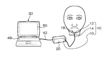
- FIG. 1 is a schematic diagram showing the configuration of a jaw movement measuring system according to an embodiment of the present invention.
- the jaw movement measuring system is connected to the acceleration detector 10, an interface device 20 that performs analog / digital conversion on the output of the acceleration detector 10, and the acceleration detector 10 via the interface device 20.
- a jaw movement measuring device 30 a jaw movement measuring device 30.
- the acceleration detector 10 includes an acceleration sensor 12 that detects acceleration in three axial directions, a flexible wiring 14 having one end connected to the acceleration sensor 12, and a connector 16 connected to the other end of the flexible wiring 14.
- the connector 16 is connected to the interface device 20.
- the acceleration sensor 12 is attached to the chin portion 18 of the lower jaw using an attachment member described later.
- the acceleration detector 10 detects a voltage signal (hereinafter, appropriately referred to as acceleration or acceleration data) corresponding to the acceleration in the three-axis directions by the acceleration sensor 12.
- the detected voltage signal is input to the interface device 20 via the flexible wiring 14 and the connector 16 and converted from an analog signal to a digital signal.
- the acceleration data converted into the digital signal is input to the jaw movement measuring device 30.
- the jaw movement measuring device 30 acquires acceleration data corresponding to the jaw movement from the acceleration detector 10, corrects an error caused by the acceleration sensor 12 with respect to the acquired acceleration data, and moves the jaw movement represented by an acceleration waveform. Measure.
- FIG. 2 is a schematic diagram showing the configuration of the peripheral portion of the acceleration sensor.
- the acceleration sensor 12 a small and lightweight three-axis acceleration sensor having a size of about 5 mm ⁇ 5 mm is preferably used.
- the small and lightweight acceleration sensor 12 does not hang down the skin of the lower chin portion 18, thereby suppressing the generation of noise due to vibration of the acceleration sensor 12.
- a chip removed from the sensor board of a commercially available acceleration sensor (3-axis acceleration sensor “AS-3ACC” manufactured by Asakusa Giken Co., Ltd.) is used as the acceleration sensor 12.
- the flexible wiring 14 a flexible wiring that is so flexible that it can be bent and is lightweight is preferably used.
- the flexible wiring 14 having high flexibility and light weight does not fluctuate the voltage signal detected by the acceleration sensor 12.
- the flexible wiring 14 in which a plurality of thin wires 14A are bundled is used according to the number of lead terminals of the acceleration sensor 12. In FIG. 2, six thin wires 14A are bundled.
- Each of the thin wires 14 ⁇ / b> A is an electric wire covered with an insulating coating, and the coating at the end is removed and soldered directly to the lead terminal of the acceleration sensor 12.
- a 0.05 mm diameter electric wire covered with expanded PTFE made by Junko Co., Ltd. is used as the fine wire 14A.
- PTFE is a tetrafluoroethylene resin, so-called Teflon (registered trademark).
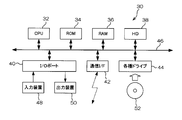
- FIG. 3 is a block diagram showing the configuration of the jaw movement measuring apparatus.
- the jaw movement measuring device 30 is composed of, for example, a computer in which a jaw movement measuring program is installed and its peripheral devices.
- the jaw movement measuring device 30 is a ROM (Read CPU) that stores various programs such as a CPU (Central Processing Unit) 32 and an OS (Operating Systems) that control the entire device and perform various operations. Only Memory) 34, RAM (Random Access Memory) 36 used as a work area when executing the program, hard disk (HD) 38 for storing various information, input / output (I / O) port 40, communication interface (I / F) ) 42 and various drives 44. These units are connected to each other by a bus 46.
- ROM Read CPU
- RAM Random Access Memory
- An input device 48 such as a keyboard and a mouse and a display device 50 such as a display are connected to the I / O port 40.
- the communication I / F 42 exchanges various information with the outside through a wired or wireless communication line.
- the communication I / F 42 is wired to the interface device 20 via a cable, and a digital signal (acceleration data) corresponding to the voltage signal output from the acceleration detector 10 is input.
- the various drives 44 are devices that read data from and write data to a computer-readable portable recording medium 52 such as a flexible disk, a magneto-optical disk, and a CD-ROM.
- the jaw movement measurement program is read from the portable recording medium 52 and stored in the ROM 34 or the hard disk 38. Alternatively, it is transmitted via the Internet, received by the communication I / F 42, and stored in the ROM 34 or the hard disk 38.
- the hard disk 38 has a database area (not shown) for storing various databases, and stores various medical databases.
- the CPU 32 reads the program from the ROM 34 or the hard disk 38 and loads it into the RAM 36.
- the RAM 36 is used as a work area, and the loaded program is executed while interacting with the user using the input device 48 and the display device 50.
- the processing routine of the jaw movement measurement program will be described later.
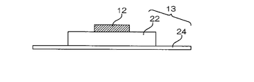
- FIG. 4A is a laminated cross-sectional view showing the structure of the mounting member.
- FIG. 4B is a schematic diagram illustrating a state in which the acceleration sensor is mounted on the chin portion 18 by the mounting member. Here, illustration of the flexible wiring 14 and the like is omitted.
- the acceleration detector 10 includes an attachment member 13 for attaching the acceleration sensor 12 to the chin portion 18 of the lower jaw.
- the mounting member 13 includes a buffer member 22 that holds the acceleration sensor 12 and absorbs vibrations of the skin, and an adhesive member 24 that bonds the acceleration sensor 12 to the lower jaw portion 18 via the buffer member 22.
- the sheet-like adhesive member 24 has a surface opposite to the surface on which the buffer member 22 is provided as an adhesive surface.
- a double-sided adhesive tape or the like having a thickness of about 1 mm can be used.
- the adhesive member 24 for example, a medical adhesive tape that is excellent in adhesion to the skin, such as used for electrocardiogram measurement, can be used.
- the mounting member 13 is mounted such that the adhesive surface of the adhesive member 24 adheres to the skin on the surface of the chin portion 18.
- the chin portion 18 is the tip of the lower jaw and has a curved shape, but the vibration of the skin is absorbed by interposing the thick buffer member 22 between the acceleration sensor 12 and the adhesive member 24. In addition, the bending of the acceleration sensor 12 is prevented.
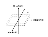
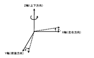
- FIG. 5 is a diagram showing the relationship between the orthogonal coordinate system of the acceleration sensor and the direction of jaw movement.
- the acceleration sensor 12 is a three-axis acceleration sensor that detects acceleration in the three-axis directions of the X-axis, Y-axis, and Z-axis of the orthogonal coordinate system.
- the lower jaw portion 18 constituting a part of the human body has a distinction between the left-right direction, the front-rear direction, and the up-down direction.
- the acceleration sensor 12 is attached to the lower jaw portion 18 so that the X-axis direction corresponds to the left-right direction, the Y-axis direction corresponds to the front-rear direction, and the Z-axis direction corresponds to the up-down direction. More specifically, as will be described later with reference to the drawings, the Y-axis direction corresponds to the tangential direction (front-rear direction) of the rotational movement around the rotational axis of the mandibular head, and the Z-axis direction corresponds to the rotational axis, the acceleration sensor 12, Corresponds to the extending direction (vertical direction) of the straight line connecting the two (see FIG. 12).
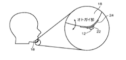
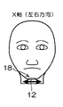
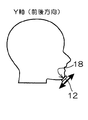
- FIG. 6A, FIG. 6B, and FIG. 6C are diagrams showing the left-right direction, the front-rear direction, and the up-down direction with respect to the chin portion of the lower jaw.
- the acceleration sensor 12 is mounted along the tangent line of the chin portion 18. When viewed from the side, the acceleration sensor 12 is disposed obliquely. Each of the directions indicated by the arrows corresponds to the left-right direction, the front-rear direction, and the up-down direction with respect to the chin portion of the lower jaw. If this is the correct mounting position and the acceleration sensor 12 is mounted at a position shifted from this position, as described below, “position shift correction” for correcting an error due to the mounting position shift is necessary.
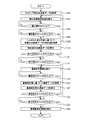
- FIG. 16 is a flowchart showing the processing routine of the jaw movement measurement program.
- step 100 the jaw movement measuring device 30 acquires acceleration data at the time of tapping.
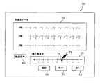
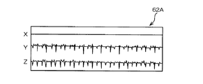
- step 102 the correction angle setting screen 60 shown in FIG. 7 is displayed on the display device 50 of the jaw movement measuring device 30.
- the correction angle setting screen 60 includes an acceleration data display unit 62, an axis selection unit 64, and an angle setting unit 66 that display acceleration data in the X-axis direction, the Y-axis direction, and the Z-axis direction. It is displayed.
- the axis selection unit 64 is configured to be able to select any of the X axis, the Y axis, and the Z axis.
- the angle setting unit 66 is configured to be able to set the correction angle ⁇ by moving the cursor 76 with a pointer 78 on, for example, a scale from ⁇ 4 to +4.
- a confirmation button 68, an end button 70, and a “next” button 72 for instructing selection of the next axis are displayed.
- the operator looks at the acceleration data display unit 62 and first confirms acceleration data in the X-axis direction. If it is determined that the amplitude of the acceleration data in the X-axis direction is large, the Z-axis is selected by operating the axis selector 64 so that the amplitude of the acceleration data in the X-axis direction is minimized (substantially zero) and setting the correction angle theta 1 about the Z-axis, to select the enter button 68.
- the jaw motion measuring device 30 confirms the X axis direction, Y based on the set correction angle in the next step 108.
- a correction value of acceleration data in the axial direction and the Z-axis direction is calculated.
- the corrected acceleration data is displayed on the acceleration data display unit 62 of the correction angle setting screen 60. As shown in FIG. 8, the data screen 62A is displayed in which the amplitude of acceleration data in the X-axis direction is substantially zero and the amplitude of acceleration data in the Y-axis direction and the Z-axis direction is increased.
- FIG. 9A and 9B are diagrams for explaining the significance of the first correction.
- the first correction when viewed from the acceleration sensor 12 side, the first correction is the acceleration sensor 12 that is mounted obliquely with respect to the left-right direction in the chin portion 18, and the X-axis direction is the left-right direction. It corresponds to the state rotated so that it may become parallel to.
- the first correction corresponds to a state in which the orthogonal coordinates are rotated around the Z axis by an angle ⁇ 1 when viewed from the orthogonal coordinates side.
- the jaw movement measuring device 30 returns to step 102 and displays the correction angle setting screen 60 shown in FIG. 7 on the display device 50 of the jaw movement measuring device 30. To display.
- the operator operates the axis selection unit 64 to select the X axis so that the amplitude of the acceleration data in the Z axis direction is minimized (substantially zero), sets the correction angle ⁇ 2 around the X axis,
- the confirm button 68 is selected.
- the Y-axis direction corresponds to the tangential direction (front-rear direction) of the rotational motion around the rotational axis of the mandibular head
- the Z-axis direction is the extending direction of the straight line connecting the rotational axis and the acceleration sensor 12. (Vertical direction) (see FIG. 12).
- the jaw movement measuring device 30 calculates the correction value of the acceleration data in the X-axis direction, the Y-axis direction, and the Z-axis direction based on the set correction angle in the same manner as in steps 104 to 110, and after the correction.
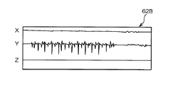
- the acceleration data is displayed on the acceleration data display unit 62 of the correction angle setting screen 60. As shown in FIG. 10, a data screen 62B is displayed in which the amplitude of the acceleration data in the Z-axis direction is reduced and the amplitude of the acceleration data in the Y-axis direction is increased.
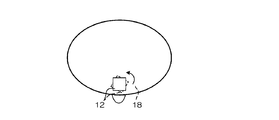
- FIG. 12A and FIG. 12B are explanatory diagrams for explaining the relationship between the jaw movement and the mounting position of the acceleration sensor.
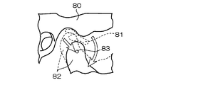
- the jaw movement is “rotation movement” around the rotation axis 83 of the mandibular head 82 with the mandible 80 as a bearing, and the mandibular head 82 moves forward relative to the mandible 80. It is classified as “sliding movement”.
- a cartilage 81 is interposed between the mandibular fossa 80 and the mandibular head 82.
- the Y-axis direction corresponds to the tangential direction (front-rear direction) of the rotational movement around the rotation axis of the mandibular head
- the Z-axis direction corresponds to the rotation axis and the acceleration sensor. 12 is attached to the chin portion 18 of the lower jaw so as to correspond to the extending direction (vertical direction) of the straight line connecting 12.
- the “tapping motion” that opens and closes the mouth and jaws at a substantially constant interval is basically the rotational motion shown in FIG. 12A, and has the most back-and-forth movement (corresponding to the Y-axis direction) with respect to the chin portion of the lower jaw. (See FIG. 6B). Therefore, in the present embodiment, the tapping motion is measured, and the amplitude of the acceleration data in the X-axis direction and the Z-axis direction is decreased (in other words, the amplitude of the acceleration data in the Y-axis direction is increased). ) Correction is performed.
- FIG. 11A and 11B are diagrams for explaining the significance of the second correction.
- the second correction when viewed from the acceleration sensor 12 side, the second correction is the acceleration sensor 12 mounted in the chin portion 18 with the Z-axis direction being inclined with respect to the vertical direction. It is equivalent to the state rotated about the X-axis direction (left-right direction) so that it may become parallel to.
- the second correction corresponds to a state in which the orthogonal coordinates are rotated around the X axis by an angle ⁇ 2 when viewed from the orthogonal coordinates side.
- the operator looks at the acceleration data display unit 62 on which the corrected data screen 62B is displayed, and confirms the acceleration data in the X-axis direction, the Y-axis direction, and the Z-axis direction.
- the end button 70 is operated to end the positional deviation correction.
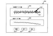
- step 114 the jaw movement measuring device 30 proceeds to step 116 and displays the baseline setting screen 84 shown in FIG. 13 on the display device 50 of the jaw movement measuring device 30.
- the baseline setting screen 84 displays an acceleration data display unit 86 that displays acceleration data in the Y-axis direction, and a speed data display unit 88 that displays speed data obtained by integrating the acceleration data in the Y-axis direction. Yes.
- a base line setting line 90 for setting the position of the base line is displayed as shown by a dotted line.
- the base line setting line 90 is configured to be moved up and down by a pointer 92 so that the position of the base line can be set.
- the base line setting screen 84 includes a confirmation button 94, an end button 96, and a “return” button 98 for instructing to return to the setting of the base line.
- the operator moves the baseline setting line 90 to set it at a predetermined position, and selects the confirm button 94.
- the jaw movement measuring device 30 integrates the acceleration data in the Y-axis direction based on the set baseline in the next step 120, and the velocity in the Y-axis direction. Calculate the data.
- the speed data after setting the base line is displayed on the speed data display unit 88 of the base line setting screen 84.
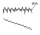
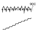
- FIG. 14A, 14B, and 14C are diagrams showing the relationship between the position of the base line and the velocity waveform.
- the acceleration data is obtained as a voltage signal proportional to the acceleration, and the zero point is not fixed. Therefore, even if this is integrated to obtain the speed, a correct value cannot be obtained.
- FIG. 14A when the position of the base line is high, the velocity waveform falls to the right.
- FIG. 14C when the position of the base line is low, the velocity waveform is at the upper right. This indicates that the base line position (that is, the zero point of the acceleration waveform) is inappropriate.
- FIG. 14B if the velocity waveform becomes flat so as to fluctuate within a certain amplitude range, the position of the base line is set appropriately.
- the operator looks at the display of the speed data display section 88, selects the “return” button 98 until the position of the base line becomes appropriate, and repeatedly sets the base line.
- the “end” button 96 is selected to fix the base line.
- step 124 When the input of the “return” instruction is confirmed in step 124, the jaw movement measuring apparatus 30 returns to step 116 and displays the baseline setting screen 84, and the set baseline is the same as in steps 118 to 122. Based on the above, the velocity data in the Y-axis direction is calculated, and the velocity data after setting the baseline is displayed. On the other hand, when the input of the end instruction is confirmed in step 126, the process proceeds to step 128.
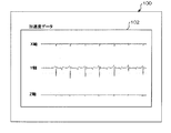
- step 128 as shown in FIG. 15, the jaw movement measurement screen 100 including the acceleration data 102 displayed based on the last set baseline is displayed. That is, the acceleration waveforms in the X-axis direction, the Y-axis direction, and the Z-axis direction are displayed together with the zero point (base line) of the acceleration waveform.
- This is a screen showing accurate measurement results of jaw movement.
- the jaw movement measurement screen 100 is displayed and the jaw movement measurement program processing routine is terminated.
- a simple detector equipped with a three-axis acceleration sensor is attached, and at the same time, a “misalignment correction” or an acceleration waveform for correcting an error caused by a misalignment of the mounting position of the acceleration sensor. It is possible to accurately measure jaw movements by performing “baseline setting” to determine the zero point of the jaw.
- a detector including a three-axis acceleration sensor is used as a small and lightweight acceleration sensor, a flexible and lightweight flexible wiring, the acceleration sensor is held and the vibration of the skin is absorbed.
- the buffer member or the like it is possible to suppress the generation of noise due to the vibration of the acceleration sensor.
- the acceleration sensor is wired to the jaw movement measuring device configured by a computer or the like.
- the acceleration sensor can perform wireless communication. Can also be used. In this case, a radio signal from the acceleration sensor is input to the communication I / F of the jaw movement measuring device.
Abstract
簡易な検出器を取り付けて、正確に顎運動の測定を行うことができる顎運動測定システムを提供する。 3軸方向の加速度を検知する加速度センサ、一端が前記加速度センサに接続されたフレキシブル配線、前記フレキシブル配線の他端に接続され且つ前記3軸方向の加速度データを出力する出力端子、及び前記加速度センサを下顎のオトガイ部に装着する装着部を、少なくとも備えた加速度検出器と、前記加速度検出器から顎運動に応じた加速度データを取得し、取得された加速度データに対し前記加速度センサに起因する誤差を補正して、加速度波形で表される顎運動を測定する顎運動測定装置と、を備えた顎運動測定システム。
Description
本発明は、顎運動測定システムに関する。
顎運動は、下顎窩を軸受けとする下顎頭の回転運動と、下顎頭が前方に移動する滑走運動とに分類される。例えば、咀嚼等で口や顎を小さく開閉する場合には、主に回転運動が発生する。一方、あくび等して口や顎を大きく開閉する場合には、回転運動だけでなく、滑走運動も発生する。これらの顎運動測定により、噛み合わせの不整合等、顎口腔機能の異常を診断することができる。適切な治療を行うためには、顎運動を対象者毎に正確に測定することが重要である。
現在、一部の臨床家の間で普及している顎運動測定装置には、株式会社ジーシー(GC)製の「ナソヘキサ」等がある。http://www.gcdental.co.jp/product/pdf/nasohekisa.pdfを参照されたい。この装置は、患者にヘッドギアと歯列に固定する器具を装着させて、咀嚼運動や開閉口運動などについて、三次元運動を測定する。即ち、下顎の相対位置を計測して、顎運動測定を行っている。例えば、他にも「キネジオグラフ」と呼ばれる装置が普及している。これは、磁石を下顎の歯列に固定をし、磁気をキャプチャーすることにより、顎運動を三次元的に測定するものである。現在の臨床現場において、顎運動を測定する装置としては、これら2つが代表的である。
また、特開2008-18094号公報(JP200818094A1)、特開2008-18010号公報(JP200818010A1)には、顎運動測定を簡易に行う技術として、下顎のオトガイ部等に加速度センサを取り付け、加速度センサの出力に基づいて被験者の口腔運動を測定する技術が種々提案されている。
http://www.gcdental.co.jp/product/pdf/nasohekisa.pdf
しかしながら、市販の顎運動測定装置は、数百万円と高価であり汎用性に欠けるという問題がある。また、患者にヘッドギアを装着させて測定を行うなど、患者側の負担が大きいという問題がある。また、測定条件が厳しく、測定専用の部屋を準備する必要があり、導入できる医院も限られている。一方、従来の加速度センサを用いた顎運動測定装置は、皮膚やコードの振動を拾うおそれがあり、また、装着方向に再現性がないため、正確な測定が行えないという問題がある。
本発明は、上記問題を解決すべく成されたものであり、簡易な検出器を取り付けて、正確に顎運動の測定を行うことができる、顎運動測定システムを提供することを目的とする。また、上記目的に加え、本発明は、市販の顎運動測定装置に比べて、安価で汎用性の高い顎運動測定システムを提供することを目的とする。
上記目的を達成するために請求項1に記載の発明は、3軸方向の加速度を検知する加速度センサ、一端が前記加速度センサに接続されたフレキシブル配線、前記フレキシブル配線の他端に接続され且つ前記3軸方向の加速度データを出力する出力端子、及び前記加速度センサを下顎のオトガイ部に装着する装着部を、少なくとも備えた加速度検出器と、前記加速度検出器から顎運動に応じた加速度データを取得し、取得された加速度データに対し前記加速度センサに起因する誤差を補正して、加速度波形で表される顎運動を測定する顎運動測定装置と、を備えた顎運動測定システムである。
請求項2の発明は、前記加速度センサは、X軸方向が左右方向に対応し、Y軸方向が前後方向に対応し、且つZ軸方向が上下方向に対応するように、下顎のオトガイ部に装着され、前記顎運動測定装置は、X軸方向の加速度データが最小になるように、前記加速度センサの直交座標をZ軸周りに回転させる第1の補正と、Z軸方向の加速度データが最小になるように、前記加速度センサの直交座標をX軸周りに回転させる第2の補正とを行い、取得された加速度データに対し前記加速度センサの装着位置ずれに起因する誤差を補正する位置ずれ補正ユニットを備えた、請求項1に記載の顎運動測定システムである。
請求項3の発明は、前記顎運動測定装置は、表示装置及び前記表示装置を制御する表示制御装置を更に備え、前記表示制御装置は、前記加速度検出器から取得された加速度データ、前記加速度センサの3軸の何れかを選択する軸選択部、及び選択された軸周りの回転角度を設定する角度設定部を、前記表示装置に表示し、前記位置ずれ補正ユニットは、前記軸選択部により選択されたZ軸周りに、前記角度設定部により設定された角度だけ加速度センサの直交座標を回転させて、X軸方向の加速度データを最小にする第1の補正を行い、前記軸選択部により選択されたX軸周りに、前記角度設定部により設定された角度だけ加速度センサの直交座標を回転させて、Z軸方向の加速度データを最小にする第2の補正を行う、請求項2に記載の顎運動測定システムである。
請求項4の発明は、前記顎運動測定装置は、Y軸方向の電圧信号を積分して得られた速度波形が一定の振幅範囲で変動するように、前記加速度検出器から取得された加速度データに対し基線を設定して加速度波形のゼロ点を定める基線設定ユニットを更に備えた、請求項1から請求項3までの何れか1項に記載の顎運動測定システムである。
請求項5の発明は、前記顎運動測定装置は、前記表示制御装置が、前記加速度検出器から取得されたY軸方向の加速度データ、及び取得された加速度データに対し基線を設定する基線設定部を、前記表示装置に表示する第1の工程と、前記基線設定ユニットが、前記基線設定部により設定された基線に基づいてY軸方向の加速度データを積分する第2の工程と、前記表示制御装置が、Y軸方向の加速度データを積分して得られた速度波形を前記表示装置に表示する第3の工程と、を基線が確定されるまで繰り返し行って、前記加速度データに対し基線を設定して加速度波形のゼロ点を定める、請求項4に記載の顎運動測定システムである。
請求項6の発明は、前記加速度センサは、下顎のオトガイ部の皮膚を下垂させない程度に、小型化且つ軽量化された請求項1から請求項5までの何れか1項に記載の顎運動測定システムである。
請求項7の発明は、前記フレキシブル配線は、前記加速度センサにより検知される加速度を変動させない程度に、可とう性が付与され且つ軽量化された請求項1から請求項6までの何れか1項に記載の顎運動測定システムである。
請求項8の発明は、前記装着部は、前記加速度センサを保持すると共に皮膚の振動を吸収する緩衝部材と、前記緩衝部材を介して前記加速度センサを下顎のオトガイ部に接着する接着部材と、を備えた請求項1から請求項7までの何れか1項に記載の顎運動測定システムである。
各請求項に係る発明によれば、以下の効果がある。
請求項1に記載の発明によれば、簡易な検出器を取り付けて、正確に顎運動の測定を行うことができる、顎運動測定システムを提供することができる、という効果がある。
請求項2に記載の発明によれば、加速度センサの装着位置ずれに起因する誤差を補正することができる、という効果がある。
請求項3に記載の発明によれば、表示画面を見ながら、リアルタイムで加速度センサの装着位置ずれに起因する誤差を補正することができる、という効果がある。
請求項4に記載の発明によれば、基線を設定して加速度波形のゼロ点を定めることができる、という効果がある。
請求項5に記載の発明によれば、表示画面を見ながら、リアルタイムで基線を設定して加速度波形のゼロ点を定めることができる、という効果がある。
請求項6、7、8に記載の発明によれば、加速度センサの振動によるノイズの発生を抑制することができる、という効果がある。
以下、図面を参照して本発明の実施の形態の一例を詳細に説明する。
<顎運動測定装置>
(全体的な装置構成)
図1は本発明の実施の形態に係る顎運動測定システムの構成を表す概略図である。図1に示すように、顎運動測定システムは、加速度検出器10と、加速度検出器10の出力をアナログ/デジタル変換するインターフェース装置20と、インターフェース装置20を介して加速度検出器10と接続される顎運動測定装置30と、を含んで構成されている。加速度検出器10は、3軸方向の加速度を検知する加速度センサ12、一端が加速度センサ12に接続されたフレキシブル配線14、及びフレキシブル配線14の他端に接続されたコネクタ16を備えている。コネクタ16は、インターフェース装置20に接続される。加速度センサ12は、後述する装着部材を用いて下顎のオトガイ部18に装着される。
加速度検出器10は、加速度センサ12により3軸方向の加速度に応じた電圧信号(以下、適宜、加速度又は加速度データという。)を検知する。検知された電圧信号は、フレキシブル配線14、及びコネクタ16を介してインターフェース装置20に入力され、アナログ信号からデジタル信号に変換される。デジタル信号に変換された加速度データは、顎運動測定装置30に入力される。顎運動測定装置30は、加速度検出器10から顎運動に応じた加速度データを取得し、取得された加速度データに対し加速度センサ12に起因する誤差を補正して、加速度波形で表される顎運動を測定する。
(加速度センサ周辺)
図2は加速度センサの周辺部の構成を表す概略図である。図2に示すように、加速度センサ12としては、5mm×5mm程度の大きさの小型且つ軽量な3軸加速度センサが好適に用いられる。小型且つ軽量な加速度センサ12は、下顎のオトガイ部18の皮膚を下垂させないので、加速度センサ12の振動によるノイズの発生を抑制する。本実施の形態では、市販されている加速度センサ(浅草技研社製の3軸加速度センサ「AS-3ACC」)のセンサボードから取り外したチップを、加速度センサ12として使用している。
図2は加速度センサの周辺部の構成を表す概略図である。図2に示すように、加速度センサ12としては、5mm×5mm程度の大きさの小型且つ軽量な3軸加速度センサが好適に用いられる。小型且つ軽量な加速度センサ12は、下顎のオトガイ部18の皮膚を下垂させないので、加速度センサ12の振動によるノイズの発生を抑制する。本実施の形態では、市販されている加速度センサ(浅草技研社製の3軸加速度センサ「AS-3ACC」)のセンサボードから取り外したチップを、加速度センサ12として使用している。
また、フレキシブル配線14としては、折り曲げ可能なほど可撓性が高く且つ軽量なフレキシブル配線が好適に用いられる。可撓性が高く且つ軽量なフレキシブル配線14は、加速度センサ12により検知される電圧信号を変動させない。本実施の形態では、加速度センサ12のリード端子の数に応じて、複数本の細線14Aが束ねられたフレキシブル配線14が用いられている。図2では6本の細線14Aが束ねられている。細線14Aの各々は、絶縁被膜で被覆された電線であり、端部の被膜が除去されて、加速度センサ12のリード端子に直接半田付けされている。本実施の形態では、細線14Aとして、潤工社製の発泡PTFEで被覆された0.05mm径の電線を用いている。PTFEとは、四フッ化エチレン樹脂、いわゆるテフロン(登録商標)である。
(顎運動測定装置)
図3は顎運動測定装置の構成を示すブロック図である。顎運動測定装置30は、例えば、顎運動測定プログラムがインストールされたコンピュータ及びその周辺機器により構成されている。顎運動測定装置30は、図3に示すように、装置全体の制御及び各種演算を行うCPU(中央処理装置; Central Processing Unit)32、OS(Operating Systems)等の各種プログラムを記憶したROM(Read Only Memory)34、プログラムの実行時にワークエリアとして使用されるRAM(Random Access Memory)36、各種情報を記憶するハードディスク(HD)38、入出力(I/O)ポート40、通信インターフェース(I/F)42、及び各種ドライブ44を備えている。これら各部は、バス46により相互に接続されている。
図3は顎運動測定装置の構成を示すブロック図である。顎運動測定装置30は、例えば、顎運動測定プログラムがインストールされたコンピュータ及びその周辺機器により構成されている。顎運動測定装置30は、図3に示すように、装置全体の制御及び各種演算を行うCPU(中央処理装置; Central Processing Unit)32、OS(Operating Systems)等の各種プログラムを記憶したROM(Read Only Memory)34、プログラムの実行時にワークエリアとして使用されるRAM(Random Access Memory)36、各種情報を記憶するハードディスク(HD)38、入出力(I/O)ポート40、通信インターフェース(I/F)42、及び各種ドライブ44を備えている。これら各部は、バス46により相互に接続されている。
I/Oポート40には、キーボードやマウス等の入力装置48と、ディスプレイ等の表示装置50と、が接続されている。通信I/F42は、有線又は無線の通信回線を介して、外部と各種情報の授受を行う。また、本実施の形態では、通信I/F42はインターフェース装置20とケーブルで有線接続されており、加速度検出器10から出力された電圧信号に対応するデジタル信号(加速度データ)が入力される。各種ドライブ44は、フレキシブルディスク、光磁気ディスク、CD-ROMなどのコンピュータ読み取り可能な可搬性記録媒体52からデータを読み込んだり、それらに対してデータを書き込んだりする装置である。
顎運動測定プログラムは、可搬性記録媒体52から読み取られて、ROM34又はハードディスク38に記憶される。或いは、インターネットを介して伝送され、通信I/F42により受信されて、ROM34又はハードディスク38に記憶される。また、ハードディスク38には、各種データベースを記憶するためのデータベース領域(図示せず)が設けられ各種の診療用データベースが記憶されている。
CPU32は、プログラムをROM34又はハードディスク38から読み出し、RAM36にロードする。そして、RAM36をワークエリアとして使用し、入力装置48及び表示装置50を用いてユーザと対話をしながら、ロードされたプログラムを実行する。顎運動測定プログラムの処理ルーチンについては後述する。
<加速度検出器の装着方法>
(オトガイ部への装着方法)
次に、加速度検出器の装着方法について説明する。図4Aは装着部材の構造を示す積層断面図である。図4Bは装着部材により加速度センサがオトガイ部18に装着された様子を示す模式図である。ここではフレキシブル配線14等の図示を省略する。図4Aに示すように、加速度検出器10は、加速度センサ12を下顎のオトガイ部18に装着するための装着部材13を備えている。
(オトガイ部への装着方法)
次に、加速度検出器の装着方法について説明する。図4Aは装着部材の構造を示す積層断面図である。図4Bは装着部材により加速度センサがオトガイ部18に装着された様子を示す模式図である。ここではフレキシブル配線14等の図示を省略する。図4Aに示すように、加速度検出器10は、加速度センサ12を下顎のオトガイ部18に装着するための装着部材13を備えている。
装着部材13は、加速度センサ12を保持すると共に皮膚の振動を吸収する緩衝部材22と、緩衝部材22を介して加速度センサ12を下顎のオトガイ部18に接着する接着部材24とを備えている。シート状の接着部材24は、緩衝部材22が設けられる面とは反対側の面が接着面とされている。緩衝部材22としては、厚さ1mm程度とやや厚めの両面接着テープ等を用いることができる。接着部材24としては、例えば、心電図測定に使用されるような、皮膚への密着性に優れる医療用の接着テープ等を用いることができる。
図4Bに示すように、装着部材13は、接着部材24の接着面が、オトガイ部18表面の皮膚に接着するようにして装着される。オトガイ部18は下顎の先端部であり、湾曲した形状を有しているが、加速度センサ12と接着部材24との間に厚めの緩衝部材22を介在させることで、皮膚の振動が吸収されるだけでなく、加速度センサ12の湾曲も防止される。
(加速度センサの直交座標系との関係)
図5は加速度センサの直交座標系と顎運動の方向との関係を示す図である。加速度センサ12は、直交座標系のX軸、Y軸、Z軸の3軸方向の加速度を検知する3軸加速度センサである。人体の一部を構成する下顎のオトガイ部18には、左右方向、前後方向、及び上下方向の区別がある。加速度センサ12は、X軸方向が左右方向に対応し、Y軸方向が前後方向に対応し、且つZ軸方向が上下方向に対応するように、下顎のオトガイ部18に装着される。図面を参照して後述する通り、より詳細には、Y軸方向が下顎頭の回転軸周りの回転運動の接線方向(前後方向)に対応し、Z軸方向が上記回転軸と加速度センサ12とを結ぶ直線の延在方向(上下方向)に対応する(図12参照)。
図5は加速度センサの直交座標系と顎運動の方向との関係を示す図である。加速度センサ12は、直交座標系のX軸、Y軸、Z軸の3軸方向の加速度を検知する3軸加速度センサである。人体の一部を構成する下顎のオトガイ部18には、左右方向、前後方向、及び上下方向の区別がある。加速度センサ12は、X軸方向が左右方向に対応し、Y軸方向が前後方向に対応し、且つZ軸方向が上下方向に対応するように、下顎のオトガイ部18に装着される。図面を参照して後述する通り、より詳細には、Y軸方向が下顎頭の回転軸周りの回転運動の接線方向(前後方向)に対応し、Z軸方向が上記回転軸と加速度センサ12とを結ぶ直線の延在方向(上下方向)に対応する(図12参照)。
図6A、図6B、及び図6Cは、下顎のオトガイ部に対する左右方向、前後方向、及び上下方向を表す図である。加速度センサ12は、オトガイ部18の接線に沿って装着される。側方から見ると、加速度センサ12は斜めに傾けて配置されている。矢印で図示した方向の各々が、下顎のオトガイ部に対する左右方向、前後方向、及び上下方向に相当する。これが正しい装着位置であり、加速度センサ12がこの位置からずれた位置に装着されると、次に説明する通り、装着位置ずれに起因する誤差を補正する「位置ずれ補正」が必要となる。
<装着位置ずれ補正>
(Z軸周りの回転 -第1の補正-)
加速度検出器10、インターフェース装置20、及び顎運動測定装置30を含む顎運動測定システムのセッティングが完了し、加速度検出器10の装着部材13により加速度センサ12の被験者へのオトガイ部18への装着が完了すると、顎運動測定装置30への加速度データの入力を開始する。また、顎運動測定装置30は、ROM34に記憶された「顎運動測定プログラム」を起動する。図16は、顎運動測定プログラムの処理ルーチンを表すフローチャートである。
(Z軸周りの回転 -第1の補正-)
加速度検出器10、インターフェース装置20、及び顎運動測定装置30を含む顎運動測定システムのセッティングが完了し、加速度検出器10の装着部材13により加速度センサ12の被験者へのオトガイ部18への装着が完了すると、顎運動測定装置30への加速度データの入力を開始する。また、顎運動測定装置30は、ROM34に記憶された「顎運動測定プログラム」を起動する。図16は、顎運動測定プログラムの処理ルーチンを表すフローチャートである。
まず、被験者に、口や顎を略一定の間隔で開閉する「タッピング運動」を行わせる。顎運動測定装置30は、ステップ100で、タッピング時の加速度データを取得する。次のステップ102で、図7に示す補正角度設定画面60を、顎運動測定装置30の表示装置50に表示する。
図7に示すように、補正角度設定画面60には、X軸方向、Y軸方向、及びZ軸方向の加速度データを表示する加速度データ表示部62、軸選択部64、及び角度設定部66が表示されている。軸選択部64は、X軸、Y軸、及びZ軸の何れかを選択可能に構成されている。角度設定部66は、例えば-4~+4までの目盛上を、ポインタ78によりカーソル76を移動させて、補正角度θを設定可能に構成されている。補正角度設定画面60には、その外に、確定ボタン68、終了ボタン70、次の軸選択を指示する「次へ」ボタン72が表示されている。
操作者は、加速度データ表示部62を見て、まず、X軸方向の加速度データを確認する。X軸方向の加速度データの振幅が大きいと判断した場合には、X軸方向の加速度データの振幅が最小(略ゼロ)になるように、軸選択部64を操作してZ軸を選択し、Z軸周りの補正角度θ1を設定して、確定ボタン68を選択する。
顎運動測定装置30は、ステップ104で軸の選択が確認され、ステップ106で確定指示の入力が確認されると、次のステップ108で、設定された補正角度に基づいて、X軸方向、Y軸方向、及びZ軸方向の加速度データの補正値を演算する。そして、ステップ110で、補正後の加速度データを、補正角度設定画面60の加速度データ表示部62に表示する。図8に示すように、X軸方向の加速度データの振幅が略ゼロとなり、Y軸方向及びZ軸方向の加速度データの振幅が大きくなったデータ画面62Aが表示される。
図9A及び図9Bは第1の補正の意義を説明する図である。図9Bに示すように、第1の補正は、加速度センサ12側から見れば、オトガイ部18において、X軸方向が左右方向に対し斜めに装着された加速度センサ12を、X軸方向が左右方向に対し平行になるように回転させた状態に相当する。図9Aに示すように、第1の補正は、直交座標側から見れば、直交座標をZ軸周りに角度θ1だけ回転させた状態に相当する。これを三次元の回転行列で表すと、下記式(1)に従って、座標(x,y,z)が座標(x’,y’,z’)に変換されたことに相当する。なお、三次元座標における回転行列において、回転角度の正方向は右ネジの方向である。結果として、z’=zとなる。

(X軸周りの回転 -第2の補正-)
操作者は、補正後のデータ画面62Aが表示された加速度データ表示部62を見て、Z軸方向の加速度データを確認する。Z軸方向の加速度データの振幅が大きいと判断した場合には、「次へ」ボタン72を操作して次の軸を選択する。Z軸方向の加速度データの振幅が適正な場合には、終了ボタン70を操作して、位置ずれ補正を終了する。
操作者は、補正後のデータ画面62Aが表示された加速度データ表示部62を見て、Z軸方向の加速度データを確認する。Z軸方向の加速度データの振幅が大きいと判断した場合には、「次へ」ボタン72を操作して次の軸を選択する。Z軸方向の加速度データの振幅が適正な場合には、終了ボタン70を操作して、位置ずれ補正を終了する。
顎運動測定装置30は、ステップ112で、「次へ」指示の選択が確認されると、ステップ102に戻って、図7に示す補正角度設定画面60を、顎運動測定装置30の表示装置50に表示する。
操作者は、Z軸方向の加速度データの振幅が最小(略ゼロ)になるように、軸選択部64を操作してX軸を選択し、X軸周りの補正角度θ2を設定して、確定ボタン68を選択する。この第2の補正により、Y軸方向が下顎頭の回転軸周りの回転運動の接線方向(前後方向)に対応し、Z軸方向が上記回転軸と加速度センサ12とを結ぶ直線の延在方向(上下方向)に対応するようになる(図12参照)。
顎運動測定装置30は、ステップ104~110と同様にして、設定された補正角度に基づいて、X軸方向、Y軸方向、及びZ軸方向の加速度データの補正値を演算し、補正後の加速度データを、補正角度設定画面60の加速度データ表示部62に表示する。図10に示すように、Z軸方向の加速度データの振幅が小さくなり、Y軸方向の加速度データの振幅が大きくなったデータ画面62Bが表示される。
図12A及び図12Bは顎運動と加速度センサの装着位置との関係を説明する説明図である。顎運動は、図12Aに矢印で図示するように、下顎窩80を軸受けとする下顎頭82の回転軸83周りの「回転運動」と、下顎窩80に対し下顎頭82が前方に移動する「滑走運動」とに分類される。なお、下顎窩80と下顎頭82との間には、軟骨81が介在している。図12Bに太い実線で図示するように、加速度センサ12は、Y軸方向が下顎頭の回転軸周りの回転運動の接線方向(前後方向)に対応し、Z軸方向が上記回転軸と加速度センサ12とを結ぶ直線の延在方向(上下方向)に対応するように、下顎のオトガイ部18に装着されている。
従って、下顎頭82が左右同時に前方に移動する「滑走運動(左右同時)」の場合は、下顎のオトガイ部に対する上下方向(Z軸方向に対応)の動きが加わる(図6C参照)。下顎頭82が左右別々に前方に移動する「滑走運動(左右変位)」の場合は、下顎のオトガイ部に対する左右方向(X軸方向に対応)の動きが加わる(図6A参照)。
口や顎を略一定の間隔で開閉する「タッピング運動」は、基本的には、図12Aに示す回転運動であり、下顎のオトガイ部に対する前後方向(Y軸方向に対応)の動きが最も多くなる(図6B参照)。従って、本実施の形態では、タッピング運動を測定すると共に、X軸方向及びZ軸方向の加速度データの振幅が小さくなるように(換言すれば、Y軸方向の加速度データの振幅が大きくなるように)補正を行うのである。
図11A及び図11Bは第2の補正の意義を説明する図である。図11Bに示すように、第2の補正は、加速度センサ12側から見れば、オトガイ部18において、Z軸方向が上下方向に対し斜めに装着された加速度センサ12を、Z軸方向が上下方向と平行になるように、X軸方向(左右方向)の周りに回転させた状態に相当する。図11Aに示すように、第2の補正は、直交座標側から見れば、直交座標をX軸周りに角度θ2だけ回転させた状態に相当する。これを三次元の回転行列で表すと、下記式(2)に従って、座標(x’,y’,z’)が座標(x”,y”,z”)に変換されたことに相当する。結果として、x”= x’となる。

操作者は、補正後のデータ画面62Bが表示された加速度データ表示部62を見て、X軸方向、Y軸方向、及びZ軸方向の加速度データを確認する。各軸方向の加速度データの振幅が適正な場合には、終了ボタン70を操作して、位置ずれ補正を終了する。
<基線設定>
顎運動測定装置30は、ステップ114で、終了指示の選択が確認されると、ステップ116に進み、図13に示す基線設定画面84を、顎運動測定装置30の表示装置50に表示する。基線設定画面84には、Y軸方向の加速度データを表示する加速度データ表示部86、及びY軸方向の加速度データを積分して得られた速度データを表示する速度データ表示部88が表示されている。
顎運動測定装置30は、ステップ114で、終了指示の選択が確認されると、ステップ116に進み、図13に示す基線設定画面84を、顎運動測定装置30の表示装置50に表示する。基線設定画面84には、Y軸方向の加速度データを表示する加速度データ表示部86、及びY軸方向の加速度データを積分して得られた速度データを表示する速度データ表示部88が表示されている。
加速度データ表示部86には、点線で図示した通り、基線の位置を設定するための基線設定ライン90が表示されている。基線設定ライン90は、ポインタ92により上下に移動させて、基線の位置を設定可能に構成されている。基線設定画面84には、その外に、確定ボタン94、終了ボタン96、基線の設定に戻ることを指示する「戻る」ボタン98が表示されている。
操作者は、基線設定ライン90を移動させて所定位置に設定し、確定ボタン94を選択する。
顎運動測定装置30は、ステップ118で、確定指示の入力が確認されると、次のステップ120で、設定された基線に基づいて、Y軸方向の加速度データを積分してY軸方向の速度データを演算する。そして、ステップ122で、基線設定後の速度データを、基線設定画面84の速度データ表示部88に表示する。
図14A、図14B、及び図14Cは、基線の位置と速度波形の関係を示す図である。加速度データは、加速度に比例した電圧信号として得られたものであり、ゼロ点は定まっていない。従って、これを積分して速度を求めても、正しい値は得られない。図14Aに示すように、基線の位置が高い場合には、速度波形は右下がりになる。これに対し、図14Cに示すように、基線の位置が低い場合には、速度波形は右上りになる。これは、いずれも基線の位置(即ち、加速度波形のゼロ点)が不適切であることを示す。一方、図14Bに示すように、速度波形が一定の振幅範囲で変動するように平坦になれば、基線の位置は適切に設定されている。
操作者は、速度データ表示部88の表示を見て、基線の位置が適切になるまで、「戻る」ボタン98を選択して、基線の設定を繰り返し行う。そして、基線の位置が適切になると、「終了」ボタン96を選択して、基線を確定させる。
顎運動測定装置30は、ステップ124で、「戻る」指示の入力が確認されると、ステップ116に戻って、基線設定画面84を表示し、ステップ118~122と同様にして、設定された基線に基づいてY軸方向の速度データを演算し、基線設定後の速度データを表示する。一方、ステップ126で、終了指示の入力が確認されると、ステップ128に進む。
ステップ128では、図15に示すように、最後に設定された基線に基づいて表示された加速度データ102を含む顎運動測定画面100を表示する。即ち、X軸方向、Y軸方向、及びZ軸方向の加速度波形を、加速度波形のゼロ点(基線)と共に表示する。これが顎運動の正確な測定結果を表す画面である。この顎運動測定画面100を表示して、顎運動測定プログラムの処理ルーチンを終了する。
以上説明した通り、本実施の形態によれば、3軸加速度センサを備えた簡易な検出器を取り付けると同時に、加速度センサの装着位置ずれに起因する誤差を補正する「位置ずれ補正」や加速度波形のゼロ点を定める「基線設定」を行って、正確に顎運動の測定を行うことができる。
また、本実施の形態によれば、被験者と共に表示画面を見ながら、リアルタイムで「位置ずれ補正」や「基線設定」を行うことができる。
また、本実施の形態によれば、3軸加速度センサを備えた検出器を、小型且つ軽量な加速度センサ、可撓性が高く且つ軽量なフレキシブル配線、加速度センサを保持すると共に皮膚の振動を吸収する緩衝部材等を用いて構成することで、加速度センサの振動によるノイズの発生を抑制することができる。
更に、上述したように、簡易な装置構成で顎運動を正確に測定できるようにしたことにより、種々の応用が可能となる。例えば、咬み合わせ診断等の早期接触の診断システムへの応用が可能になる。また、顎運動のなめらかさ(すなわち加速度を時間微分した値)を測定(、算出)することで、咀嚼運動を評価するための新たなパラメータの提案にも繋がる。また、軽量化、コードレス化することにより、要介護者の摂食状況や会話などの測定も可能となり、QOL(Quarity of Life)が客観的な数値として定量化されることが期待される。また、近年患者数が増加している緊張性頭痛や、かみ合わせ違和感、の直接的な原因と考えられているTooth Contacting Habbit(上下顎の歯牙を定常的に接触させる習慣)の確定診断機器としての応用も可能となる。
なお、上記の実施の形態では、「位置ずれ補正」後に「基線設定」を行う例について説明したが、「基線設定」後に「位置ずれ補正」を行う場合もある。また、「Z軸周りの回転(第1の補正)」後に「X軸周りの回転(第2の補正)」を行う例について説明したが、「X軸周りの回転(第2の補正)」後に「Z軸周りの回転(第1の補正)」を行うこともできる。
また、上記の実施の形態では、加速度センサがコンピュータ等で構成された顎運動測定装置に有線接続される例について説明したが、小型且つ軽量の加速度センサであれば、無線通信が可能な加速度センサを用いることもできる。この場合には、顎運動測定装置の通信I/Fに、加速度センサからの無線信号が入力される。
Claims (8)
- 3軸方向の加速度を検知する加速度センサ、一端が前記加速度センサに接続されたフレキシブル配線、前記フレキシブル配線の他端に接続され且つ前記3軸方向の加速度データを出力する出力端子、及び前記加速度センサを下顎のオトガイ部に装着する装着部を、少なくとも備えた加速度検出器と、
前記加速度検出器から顎運動に応じた加速度データを取得し、取得された加速度データに対し前記加速度センサに起因する誤差を補正して、加速度波形で表される顎運動を測定する顎運動測定装置と、
を備えた顎運動測定システム。 - 前記加速度センサは、X軸方向が左右方向に対応し、Y軸方向が前後方向に対応し、且つZ軸方向が上下方向に対応するように、下顎のオトガイ部に装着され、
前記顎運動測定装置は、X軸方向の加速度データが最小になるように、前記加速度センサの直交座標をZ軸周りに回転させる第1の補正と、Z軸方向の加速度データが最小になるように、前記加速度センサの直交座標をX軸周りに回転させる第2の補正とを行い、取得された加速度データに対し前記加速度センサの装着位置ずれに起因する誤差を補正する位置ずれ補正ユニットを備えた、
請求項1に記載の顎運動測定システム。 - 前記顎運動測定装置は、表示装置及び前記表示装置を制御する表示制御装置を更に備え、前記表示制御装置は、前記加速度検出器から取得された加速度データ、前記加速度センサの3軸の何れかを選択する軸選択部、及び選択された軸周りの回転角度を設定する角度設定部を、前記表示装置に表示し、
前記位置ずれ補正ユニットは、前記軸選択部により選択されたZ軸周りに、前記角度設定部により設定された角度だけ加速度センサの直交座標を回転させて、X軸方向の加速度データを最小にする第1の補正を行い、前記軸選択部により選択されたX軸周りに、前記角度設定部により設定された角度だけ加速度センサの直交座標を回転させて、Z軸方向の加速度データを最小にする第2の補正を行う、
請求項2に記載の顎運動測定システム。 - 前記顎運動測定装置は、Y軸方向の電圧信号を積分して得られた速度波形が一定の振幅範囲で変動するように、前記加速度検出器から取得された加速度データに対し基線を設定して加速度波形のゼロ点を定める基線設定ユニットを更に備えた、
請求項1から請求項3までの何れか1項に記載の顎運動測定システム。 - 前記顎運動測定装置は、
前記表示制御装置が、前記加速度検出器から取得されたY軸方向の加速度データ、及び取得された加速度データに対し基線を設定する基線設定部を、前記表示装置に表示する第1の工程と、前記基線設定ユニットが、前記基線設定部により設定された基線に基づいてY軸方向の加速度データを積分する第2の工程と、前記表示制御装置が、Y軸方向の加速度データを積分して得られた速度波形を前記表示装置に表示する第3の工程と、を基線が確定されるまで繰り返し行って、
前記加速度データに対し基線を設定して加速度波形のゼロ点を定める、
請求項4に記載の顎運動測定システム。 - 前記加速度センサは、下顎のオトガイ部の皮膚を下垂させない程度に、小型化且つ軽量化された請求項1から請求項5までの何れか1項に記載の顎運動測定システム。
- 前記フレキシブル配線は、前記加速度センサにより検知される加速度を変動させない程度に、可とう性が付与され且つ軽量化された請求項1から請求項6までの何れか1項に記載の顎運動測定システム。
- 前記装着部は、前記加速度センサを保持すると共に皮膚の振動を吸収する緩衝部材と、前記緩衝部材を介して前記加速度センサを下顎のオトガイ部に接着する接着部材と、を備えた請求項1から請求項7までの何れか1項に記載の顎運動測定システム。
Priority Applications (1)
| Application Number | Priority Date | Filing Date | Title |
|---|---|---|---|
| US13/203,272 US8544322B2 (en) | 2009-02-27 | 2010-02-25 | Jaw motion measuring system |
Applications Claiming Priority (2)
| Application Number | Priority Date | Filing Date | Title |
|---|---|---|---|
| JP2009-047257 | 2009-02-27 | ||
| JP2009047257A JP5350016B2 (ja) | 2009-02-27 | 2009-02-27 | 顎運動測定システム |
Publications (1)
| Publication Number | Publication Date |
|---|---|
| WO2010098388A1 true WO2010098388A1 (ja) | 2010-09-02 |
Family
ID=42665592
Family Applications (1)
| Application Number | Title | Priority Date | Filing Date |
|---|---|---|---|
| PCT/JP2010/052974 WO2010098388A1 (ja) | 2009-02-27 | 2010-02-25 | 顎運動測定システム |
Country Status (3)
| Country | Link |
|---|---|
| US (1) | US8544322B2 (ja) |
| JP (1) | JP5350016B2 (ja) |
| WO (1) | WO2010098388A1 (ja) |
Families Citing this family (22)
| Publication number | Priority date | Publication date | Assignee | Title |
|---|---|---|---|---|
| WO2014146016A2 (en) | 2013-03-15 | 2014-09-18 | Alfred E. Mann Foundation For Scientific Research | Current sensing multiple output current stimulators with fast turn on time |
| JP6781865B2 (ja) | 2013-07-29 | 2020-11-11 | アルフレッド イー. マン ファウンデーション フォー サイエンティフィック リサーチ | マイクロプロセッサ制御されたeクラスドライバ |
| JP6795491B2 (ja) | 2014-08-15 | 2020-12-02 | アクソニクス モジュレーション テクノロジーズ インコーポレイテッド | 膀胱機能不全およびその他の症状を緩和するための神経刺激のための埋込可能導線添着構造 |
| EP3180075A4 (en) | 2014-08-15 | 2018-03-07 | Axonics Modulation Technologies Inc. | Integrated electromyographic clinician programmer for use with an implantable neurostimulator |
| US9555246B2 (en) | 2014-08-15 | 2017-01-31 | Axonics Modulation Technologies, Inc. | Electromyographic lead positioning and stimulation titration in a nerve stimulation system for treatment of overactive bladder |
| CA2957967C (en) | 2014-08-15 | 2018-11-27 | Axonics Modulation Technologies, Inc. | Systems and methods for neurostimulation electrode configurations based on neural localization |
| AU2015301489B2 (en) | 2014-08-15 | 2020-01-23 | Axonics Modulation Technologies, Inc. | External pulse generator device and associated methods for trial nerve stimulation |
| AU2015318076B2 (en) * | 2014-09-15 | 2018-08-30 | Attenti Electronic Monitoring Ltd. | Impairment detection |
| JP6775951B2 (ja) * | 2014-12-27 | 2020-10-28 | 三栄源エフ・エフ・アイ株式会社 | 飲食物の嚥下感覚の評価方法 |
| AU2016205049B2 (en) | 2015-01-09 | 2020-05-14 | Axonics Modulation Technologies, Inc. | Improved antenna and methods of use for an implantable nerve stimulator |
| ES2725489T3 (es) | 2015-01-09 | 2019-09-24 | Axonics Modulation Tech Inc | Control remoto del paciente y procedimientos de uso asociados con un sistema de estimulación nerviosa |
| AU2016205050B2 (en) | 2015-01-09 | 2020-02-27 | Axonics Modulation Technologies, Inc. | Attachment devices and associated methods of use with a nerve stimulation charging device |
| WO2017011305A1 (en) | 2015-07-10 | 2017-01-19 | Axonics Modulation Technologies, Inc. | Implantable nerve stimulator having internal electronics without asic and methods of use |
| EP3407965B1 (en) | 2016-01-29 | 2021-03-03 | Axonics Modulation Technologies, Inc. | Systems for frequency adjustment to optimize charging of implantable neurostimulator |
| AU2017218157B2 (en) | 2016-02-12 | 2022-09-29 | Axonics, Inc. | External pulse generator device and associated methods for trial nerve stimulation |
| US20170265801A1 (en) * | 2016-03-15 | 2017-09-21 | Aalok Nital Patwa | Bruxism Detection System With Chin-Mounted Accelerometer Sensor |
| JP2021513902A (ja) | 2018-02-22 | 2021-06-03 | アクソニクス モジュレーション テクノロジーズ インコーポレイテッド | 試験的神経刺激のための神経刺激リードおよび使用方法 |
| WO2020185902A1 (en) | 2019-03-11 | 2020-09-17 | Axonics Modulation Technologies, Inc. | Charging device with off-center coil |
| US11848090B2 (en) | 2019-05-24 | 2023-12-19 | Axonics, Inc. | Trainer for a neurostimulator programmer and associated methods of use with a neurostimulation system |
| US11439829B2 (en) | 2019-05-24 | 2022-09-13 | Axonics, Inc. | Clinician programmer methods and systems for maintaining target operating temperatures |
| TWI702941B (zh) * | 2019-11-28 | 2020-09-01 | 長庚醫療財團法人林口長庚紀念醫院 | 下頜張合力量與施力穩定狀態檢測裝置 |
| CN114287361B (zh) * | 2022-01-20 | 2022-12-23 | 中国农业科学院农业信息研究所 | 一种牲畜行为监测分析系统及方法 |
Citations (3)
| Publication number | Priority date | Publication date | Assignee | Title |
|---|---|---|---|---|
| JPS6361121A (ja) * | 1986-09-01 | 1988-03-17 | Canon Inc | 振動検出装置用出力補正装置 |
| JPH10124245A (ja) * | 1996-10-18 | 1998-05-15 | Ricoh Co Ltd | ペン型入力装置 |
| JP2008307207A (ja) * | 2007-06-14 | 2008-12-25 | Advanced Telecommunication Research Institute International | 動作計測装置 |
Family Cites Families (3)
| Publication number | Priority date | Publication date | Assignee | Title |
|---|---|---|---|---|
| JPH10124254A (ja) | 1996-10-21 | 1998-05-15 | Nisshin Koki Kk | 光学式マウスシステム |
| JP5077522B2 (ja) | 2006-07-12 | 2012-11-21 | 株式会社東京技研 | 摂食機能測定装置 |
| JP5082127B2 (ja) | 2006-07-13 | 2012-11-28 | 株式会社東京技研 | 口腔運動測定装置 |
-
2009
- 2009-02-27 JP JP2009047257A patent/JP5350016B2/ja not_active Expired - Fee Related
-
2010
- 2010-02-25 US US13/203,272 patent/US8544322B2/en not_active Expired - Fee Related
- 2010-02-25 WO PCT/JP2010/052974 patent/WO2010098388A1/ja active Application Filing
Patent Citations (3)
| Publication number | Priority date | Publication date | Assignee | Title |
|---|---|---|---|---|
| JPS6361121A (ja) * | 1986-09-01 | 1988-03-17 | Canon Inc | 振動検出装置用出力補正装置 |
| JPH10124245A (ja) * | 1996-10-18 | 1998-05-15 | Ricoh Co Ltd | ペン型入力装置 |
| JP2008307207A (ja) * | 2007-06-14 | 2008-12-25 | Advanced Telecommunication Research Institute International | 動作計測装置 |
Non-Patent Citations (2)
| Title |
|---|
| IVICA PELIVAN ET AL.: "Tri-axial Accelerometric Analysis of Dynamic Patterns of Mandibular Movements", INTERNATIONAL POSTER JOURNAL OF DENTISTRY AND ORAL MEDICINE, vol. 2, no. 2, 2007, Retrieved from the Internet <URL:http://ipj.quintessenz.de/index.php?content=awards&doc=poster&select=360> [retrieved on 20100527] * |
| KUNITAKA ISAJI ET AL.: "Shika Ryoiki ni Okeru Kasokudo Sensor no Oyo", CHIIKI IRYO, 2002, pages 604 - 606 * |
Also Published As
| Publication number | Publication date |
|---|---|
| JP2010200856A (ja) | 2010-09-16 |
| JP5350016B2 (ja) | 2013-11-27 |
| US20120048013A1 (en) | 2012-03-01 |
| US8544322B2 (en) | 2013-10-01 |
Similar Documents
| Publication | Publication Date | Title |
|---|---|---|
| JP5350016B2 (ja) | 顎運動測定システム | |
| US20210014617A1 (en) | Detecting Use of a Wearable Device | |
| JP6112300B2 (ja) | マスタースレーブロボットの制御装置及び制御方法、マスタースレーブロボット、並びに、制御プログラム | |
| Barlow et al. | A new head-mounted lip-jaw movement transduction system for the study of motor speech disorders | |
| KR101801444B1 (ko) | 치아 부착용 웨어러블 장치 | |
| JP2010200856A5 (ja) | ||
| WO2007021007A1 (ja) | 歯の咬み合わせ修正支援装置、プログラム、及び記録媒体 | |
| Lin et al. | Novel assembled sensorized glove platform for comprehensive hand function assessment by using inertial sensors and force sensing resistors | |
| JP2018196580A (ja) | 歯列矯正支援方法および歯列矯正支援システム | |
| CN105030364A (zh) | 牙齿横纵向倾斜角度的测量方法 | |
| Mostashiri et al. | A novel spatial mandibular motion-capture system based on planar fiducial markers | |
| CN110624209B (zh) | 健身设备、数据监控方法及其装置、计算机可读存储介质 | |
| CN112790888A (zh) | 下颌运动捕捉系统、捕捉方法以及模拟方法 | |
| JP5273432B2 (ja) | コントローラ | |
| JP6385194B2 (ja) | 筋トーヌス計測装置 | |
| CN108066034B (zh) | 牙齿受力测量装置及方法 | |
| JP3855038B2 (ja) | 剛体運動測定方法、剛体運動測定装置、剛体運動測定プログラム、顎運動測定方法、顎運動測定装置および顎運動測定プログラム | |
| WO2022176943A1 (ja) | 口腔内カメラシステム及び画像表示方法 | |
| TWI616193B (zh) | 口腔咬合路徑量測裝置、用於感測一口腔咬合運動的方法、以及用於感測一口腔運動的裝置 | |
| JP5363181B2 (ja) | 歯牙模型、歯列模型、顎模型、頭部模型、医療用実習装置 | |
| US20110191083A1 (en) | System and Method for Measuring and Reporting the Relative Functions of Dental Anatomical Structures | |
| Farook et al. | A 3D printed electronic wearable device to generate vertical, horizontal and phono-articulatory jaw movement parameters: A concept implementation | |
| CN214511395U (zh) | 下颌运动捕捉系统 | |
| Hayashi et al. | Comparison of the finite helical axis and the rectangular coordinate system in representing orthodontic tooth movement | |
| EP3682847A1 (en) | Occlusal pressure analysis device, occlusal pressure analysis program, and occlusal pressure analysis method |
Legal Events
| Date | Code | Title | Description |
|---|---|---|---|
| 121 | Ep: the epo has been informed by wipo that ep was designated in this application |
Ref document number: 10746267 Country of ref document: EP Kind code of ref document: A1 |
|
| DPE1 | Request for preliminary examination filed after expiration of 19th month from priority date (pct application filed from 20040101) | ||
| NENP | Non-entry into the national phase |
Ref country code: DE |
|
| WWE | Wipo information: entry into national phase |
Ref document number: 13203272 Country of ref document: US |
|
| 122 | Ep: pct application non-entry in european phase |
Ref document number: 10746267 Country of ref document: EP Kind code of ref document: A1 |