WO2010098169A1 - 加工装置及び加工方法 - Google Patents
加工装置及び加工方法 Download PDFInfo
- Publication number
- WO2010098169A1 WO2010098169A1 PCT/JP2010/051206 JP2010051206W WO2010098169A1 WO 2010098169 A1 WO2010098169 A1 WO 2010098169A1 JP 2010051206 W JP2010051206 W JP 2010051206W WO 2010098169 A1 WO2010098169 A1 WO 2010098169A1
- Authority
- WO
- WIPO (PCT)
- Prior art keywords
- point
- distance
- coordinates
- points
- coordinate
- Prior art date
Links
Images


Classifications
-
- B—PERFORMING OPERATIONS; TRANSPORTING
- B23—MACHINE TOOLS; METAL-WORKING NOT OTHERWISE PROVIDED FOR
- B23Q—DETAILS, COMPONENTS, OR ACCESSORIES FOR MACHINE TOOLS, e.g. ARRANGEMENTS FOR COPYING OR CONTROLLING; MACHINE TOOLS IN GENERAL CHARACTERISED BY THE CONSTRUCTION OF PARTICULAR DETAILS OR COMPONENTS; COMBINATIONS OR ASSOCIATIONS OF METAL-WORKING MACHINES, NOT DIRECTED TO A PARTICULAR RESULT
- B23Q17/00—Arrangements for observing, indicating or measuring on machine tools
- B23Q17/22—Arrangements for observing, indicating or measuring on machine tools for indicating or measuring existing or desired position of tool or work
-
- B—PERFORMING OPERATIONS; TRANSPORTING
- B23—MACHINE TOOLS; METAL-WORKING NOT OTHERWISE PROVIDED FOR
- B23Q—DETAILS, COMPONENTS, OR ACCESSORIES FOR MACHINE TOOLS, e.g. ARRANGEMENTS FOR COPYING OR CONTROLLING; MACHINE TOOLS IN GENERAL CHARACTERISED BY THE CONSTRUCTION OF PARTICULAR DETAILS OR COMPONENTS; COMBINATIONS OR ASSOCIATIONS OF METAL-WORKING MACHINES, NOT DIRECTED TO A PARTICULAR RESULT
- B23Q17/00—Arrangements for observing, indicating or measuring on machine tools
- B23Q17/24—Arrangements for observing, indicating or measuring on machine tools using optics or electromagnetic waves
-
- G—PHYSICS
- G05—CONTROLLING; REGULATING
- G05B—CONTROL OR REGULATING SYSTEMS IN GENERAL; FUNCTIONAL ELEMENTS OF SUCH SYSTEMS; MONITORING OR TESTING ARRANGEMENTS FOR SUCH SYSTEMS OR ELEMENTS
- G05B19/00—Programme-control systems
- G05B19/02—Programme-control systems electric
- G05B19/18—Numerical control [NC], i.e. automatically operating machines, in particular machine tools, e.g. in a manufacturing environment, so as to execute positioning, movement or co-ordinated operations by means of programme data in numerical form
- G05B19/401—Numerical control [NC], i.e. automatically operating machines, in particular machine tools, e.g. in a manufacturing environment, so as to execute positioning, movement or co-ordinated operations by means of programme data in numerical form characterised by control arrangements for measuring, e.g. calibration and initialisation, measuring workpiece for machining purposes
-
- G—PHYSICS
- G05—CONTROLLING; REGULATING
- G05B—CONTROL OR REGULATING SYSTEMS IN GENERAL; FUNCTIONAL ELEMENTS OF SUCH SYSTEMS; MONITORING OR TESTING ARRANGEMENTS FOR SUCH SYSTEMS OR ELEMENTS
- G05B19/00—Programme-control systems
- G05B19/02—Programme-control systems electric
- G05B19/18—Numerical control [NC], i.e. automatically operating machines, in particular machine tools, e.g. in a manufacturing environment, so as to execute positioning, movement or co-ordinated operations by means of programme data in numerical form
- G05B19/4093—Numerical control [NC], i.e. automatically operating machines, in particular machine tools, e.g. in a manufacturing environment, so as to execute positioning, movement or co-ordinated operations by means of programme data in numerical form characterised by part programming, e.g. entry of geometrical information as taken from a technical drawing, combining this with machining and material information to obtain control information, named part programme, for the NC machine
- G05B19/40937—Numerical control [NC], i.e. automatically operating machines, in particular machine tools, e.g. in a manufacturing environment, so as to execute positioning, movement or co-ordinated operations by means of programme data in numerical form characterised by part programming, e.g. entry of geometrical information as taken from a technical drawing, combining this with machining and material information to obtain control information, named part programme, for the NC machine concerning programming of machining or material parameters, pocket machining
-
- G—PHYSICS
- G05—CONTROLLING; REGULATING
- G05B—CONTROL OR REGULATING SYSTEMS IN GENERAL; FUNCTIONAL ELEMENTS OF SUCH SYSTEMS; MONITORING OR TESTING ARRANGEMENTS FOR SUCH SYSTEMS OR ELEMENTS
- G05B2219/00—Program-control systems
- G05B2219/30—Nc systems
- G05B2219/37—Measurements
- G05B2219/37425—Distance, range
-
- G—PHYSICS
- G05—CONTROLLING; REGULATING
- G05B—CONTROL OR REGULATING SYSTEMS IN GENERAL; FUNCTIONAL ELEMENTS OF SUCH SYSTEMS; MONITORING OR TESTING ARRANGEMENTS FOR SUCH SYSTEMS OR ELEMENTS
- G05B2219/00—Program-control systems
- G05B2219/30—Nc systems
- G05B2219/37—Measurements
- G05B2219/37575—Pre-process, measure workpiece before machining
-
- G—PHYSICS
- G05—CONTROLLING; REGULATING
- G05B—CONTROL OR REGULATING SYSTEMS IN GENERAL; FUNCTIONAL ELEMENTS OF SUCH SYSTEMS; MONITORING OR TESTING ARRANGEMENTS FOR SUCH SYSTEMS OR ELEMENTS
- G05B2219/00—Program-control systems
- G05B2219/30—Nc systems
- G05B2219/37—Measurements
- G05B2219/37582—Position, angle of workpiece surface
-
- G—PHYSICS
- G05—CONTROLLING; REGULATING
- G05B—CONTROL OR REGULATING SYSTEMS IN GENERAL; FUNCTIONAL ELEMENTS OF SUCH SYSTEMS; MONITORING OR TESTING ARRANGEMENTS FOR SUCH SYSTEMS OR ELEMENTS
- G05B2219/00—Program-control systems
- G05B2219/30—Nc systems
- G05B2219/49—Nc machine tool, till multiple
- G05B2219/49323—Machine long, slender workpiece
-
- Y—GENERAL TAGGING OF NEW TECHNOLOGICAL DEVELOPMENTS; GENERAL TAGGING OF CROSS-SECTIONAL TECHNOLOGIES SPANNING OVER SEVERAL SECTIONS OF THE IPC; TECHNICAL SUBJECTS COVERED BY FORMER USPC CROSS-REFERENCE ART COLLECTIONS [XRACs] AND DIGESTS
- Y02—TECHNOLOGIES OR APPLICATIONS FOR MITIGATION OR ADAPTATION AGAINST CLIMATE CHANGE
- Y02P—CLIMATE CHANGE MITIGATION TECHNOLOGIES IN THE PRODUCTION OR PROCESSING OF GOODS
- Y02P90/00—Enabling technologies with a potential contribution to greenhouse gas [GHG] emissions mitigation
- Y02P90/02—Total factory control, e.g. smart factories, flexible manufacturing systems [FMS] or integrated manufacturing systems [IMS]
Definitions
- the present invention relates to a machining apparatus and a machining method for performing machining, and more particularly to a machining apparatus and a machining method for performing high-precision machining by setting a tool path based on preprocess measurement.
- Aircraft sheet metal parts and composite material parts are molded into a predetermined shape and then trimmed to the regular dimensions specified in the drawing.
- Trimming methods include marking a part with a dedicated jig and trimming along the marking line, moving the tool along a dedicated guide jig fixed to the part, and trimming.
- a method of performing trim processing using an NC (numerical control) processing device are known.
- the method of trimming along the marking line is difficult to automate.
- a dedicated jig is required for each part, and the alignment when attaching the jig to the part is required. It must be done strictly. Even in a method of performing trim processing using an NC processing apparatus, it is necessary to strictly align parts.
- Japanese Patent Application Laid-Open No. 2005-342865 discloses a processing apparatus for performing trim processing following the shape of a part.
- the processing apparatus includes a tool for trimming a workpiece and a guide jig.
- the guide jig includes a contact portion and a holding portion attached to the contact portion.
- the holding unit holds the tool.
- the contact portion includes a contact surface that contacts a reference surface extending in the longitudinal direction of the workpiece, and moves in the longitudinal direction in a state where the contact surface is in contact with the reference surface.
- the tool moves along a trajectory corresponding to the shape of the reference surface to form a trim shape on the workpiece. According to the trim processing that follows the shape of the part, exact alignment is not necessary.
- Japanese Patent Application Laid-Open No. 11-123634 discloses another processing apparatus for performing trim processing following the shape of a part.
- the machining apparatus includes a machining tool unit, a numerical control unit, a measuring unit, and a tool path deriving unit.
- the measuring means is driven and controlled by the numerical controller and measures the dimensional distribution of the workpiece.
- the tool path deriving unit derives a tool path based on the measurement result of the measuring unit.
- the numerical control unit moves the machining tool unit along the tool path.
- JP 2005-342865 A Japanese Patent Laid-Open No. 11-123634
- An object of the present invention is to provide a machining apparatus and a machining method that do not require exact positioning of a workpiece and that can machine the workpiece into a desired shape.
- a processing apparatus includes a first portion, a first servomotor that drives the first portion in a first direction, a distance sensor provided in the first portion, and the first direction.
- a second portion supported by the first portion so as to be movable in a second direction orthogonal to the second portion, a second servo motor for driving the second portion in the second direction, and a control device.
- the second part supports a tool for machining a workpiece.
- the distance sensor measures a distance in the second direction to the reference surface of the workpiece and outputs a distance signal indicating the distance when the distance sensor is at each of the plurality of positions in the first direction.
- the control device generates measurement data indicating a relationship between coordinates in the first direction of a plurality of points on the reference surface and a distance to the distance sensor based on the distance signal, and based on the measurement data, A step coordinate range as a coordinate range in the first direction of a step formed on a reference plane is determined, control data indicating a trajectory of the tool is generated based on the measurement data and the step coordinate range, and the control data Based on the above, the first servo motor and the second servo motor are numerically controlled.
- the trajectory includes a first trajectory portion in which coordinates in the first direction are not included in the step coordinate range, and a second trajectory portion in which coordinates in the first direction are included in the step coordinate range.
- the control device calculates a portion corresponding to the first locus portion of the control data based on a first offset value, and calculates a portion corresponding to the second locus portion of the control data based on a second offset value. calculate.
- the reference surface is a curved surface
- the second direction is a radial direction
- the first direction is a rotational direction of the radial.
- the processing apparatus includes: a first work support part that supports the work; a second work support part that supports the work; and a base to which the first work support part and the second work support part are fixed. Is further provided.
- the first servo motor turns the first portion around a turning axis.
- a first positioning means group for positioning the first work support portion and a second positioning means group for positioning the second work support portion are provided on the base.
- the first positioning means group is disposed along a first radius centered on the pivot axis.
- the second positioning means group is disposed along a second radius centered on the pivot axis.
- the control data includes a coordinate theta k of the first direction of the point U k on the trajectory, the coordinates T k of the second direction of the point U k, the point U k + 1 on the trajectory A coordinate ⁇ k + 1 in the first direction and a coordinate T k + 1 in the second direction of the point U k + 1 are shown.
- the control device controls the first servo motor and the second servo motor so that the tool passes through a point U x having a coordinate ⁇ x in the first direction between the coordinates ⁇ k and the coordinates ⁇ k + 1. To do.
- T x T k + ⁇ ( ⁇ x ⁇ k ) / ( ⁇ k + 1 ⁇ k ) ⁇ ⁇ (T k + 1 ⁇ T k ) Meet.
- the control device generates step determination data based on the measurement data, and determines the step coordinate range based on the step determination data.
- the step determination data includes a distance in the second direction from the distance sensor to the point of interest and a point next to the point of interest among the points from the distance sensor for the point of interest as one of the plurality of points. The relationship between the difference of the distance of the said 2nd direction to a point and the coordinate of the said 1st direction of the said attention point is shown.
- the control device generates step determination data based on the measurement data, and determines the step coordinate range based on the step determination data.
- the step determination data includes, for an attention point as one of the plurality of points, a radius of a circle passing through three consecutive points including the attention point among the plurality of points, and coordinates in the first direction of the attention point. The relationship is shown.
- the control device generates step determination data based on the measurement data, and determines the step coordinate range based on the step determination data.
- the step determination data includes, for the attention point as one of the plurality of points, the distance between the center of a circle passing through three consecutive points including the attention point and the predetermined point of the plurality of points, The relationship with the coordinate of the said 1st direction is shown.
- the control device generates step determination data based on the measurement data, and determines the step coordinate range based on the step determination data.
- the step determination data includes, for an attention point as one of the plurality of points, a radius of a circle passing through three consecutive points including the attention point among the plurality of points, and coordinates in the first direction of the attention point. The relationship between the distance between the center of the circle and a predetermined point and the coordinates of the attention point in the first direction is shown.
- the machining method provides a method in which a distance sensor provided in a first portion driven in a first direction by a first servomotor is at each of a plurality of positions in the first direction. Measuring a distance in a second direction perpendicular to the first direction to the reference plane and outputting a distance signal indicating the distance; and a plurality of first points on the reference plane based on the distance signal A step of generating measurement data indicating a relationship between a coordinate of a direction and a distance to the distance sensor; and a step coordinate range as a coordinate range of the step formed on the reference plane based on the measurement data in the first direction A step of generating control data indicating a trajectory of a tool for machining the workpiece based on the measurement data and the step coordinate range, and the first service based on the control data.
- the tool is supported on the second part.
- the second part is supported by the first part so as to be movable in the second direction.
- the second portion is driven in the second direction by the second servomotor.
- the trajectory includes a first trajectory portion in which coordinates in the first direction are not included in the step coordinate range, and a second trajectory portion in which coordinates in the first direction are included in the step coordinate range.
- the step of determining the step coordinate range includes calculating a portion corresponding to the first locus portion of the control data based on a first offset value, and the second of the control data based on a second offset value. Calculating a portion corresponding to the locus portion.
- the reference surface is a curved surface
- the second direction is a radial direction
- the first direction is a rotational direction of the radial.
- the first servo motor turns the first portion around a turning axis.
- the machining method includes a step of adjusting a first radial position of the first workpiece support portion that should support the workpiece in the first radial direction around the rotation axis, and the rotation axis of the second workpiece support portion that should support the workpiece. And adjusting the second radial position about the center.
- the control data includes a coordinate theta k of the first direction of the point U k on the trajectory, the coordinates T k of the second direction of the point U k, the point U k + 1 on the trajectory A coordinate ⁇ k + 1 in the first direction and a coordinate T k + 1 in the second direction of the point U k + 1 are shown.
- the tool passes through a point U x having a coordinate ⁇ x in the first direction between the coordinates ⁇ k and the coordinates ⁇ k + 1. And numerically controlling the first servo motor and the second servo motor.
- T x T k + ⁇ ( ⁇ x ⁇ k ) / ( ⁇ k + 1 ⁇ k ) ⁇ ⁇ (T k + 1 ⁇ T k ) Meet.
- the step of determining the step coordinate range includes a step of generating step determination data based on the measurement data and a step of determining the step coordinate range based on the step determination data.
- the step determination data includes a distance in the second direction from the distance sensor to the point of interest and a point next to the point of interest among the points from the distance sensor for the point of interest as one of the plurality of points. The relationship between the difference of the distance of the said 2nd direction to a point and the coordinate of the said 1st direction of the said attention point is shown.
- the step of determining the step coordinate range includes a step of generating step determination data based on the measurement data and a step of determining the step coordinate range based on the step determination data.
- the step determination data includes, for an attention point as one of the plurality of points, a radius of a circle passing through three consecutive points including the attention point among the plurality of points, and coordinates in the first direction of the attention point. The relationship is shown.
- the step of determining the step coordinate range includes a step of generating step determination data based on the measurement data and a step of determining the step coordinate range based on the step determination data.
- the step determination data includes, for the attention point as one of the plurality of points, the distance between the center of a circle passing through three consecutive points including the attention point and the predetermined point of the plurality of points, The relationship with the coordinate of the said 1st direction is shown.
- the step of determining the step coordinate range includes a step of generating step determination data based on the measurement data and a step of determining the step coordinate range based on the step determination data.
- the step determination data includes, for an attention point as one of the plurality of points, a radius of a circle passing through three consecutive points including the attention point among the plurality of points, and coordinates in the first direction of the attention point. The relationship between the distance between the center of the circle and a predetermined point and the coordinates of the attention point in the first direction is shown.
- a machining apparatus and a machining method that do not require exact alignment of a workpiece and that can machine the workpiece into a desired shape.
- FIG. 1 is a top view of a processing apparatus according to the first embodiment of the present invention.
- FIG. 2 is a side view of the processing apparatus according to the first embodiment.
- FIG. 3 is a cross-sectional view of the workpiece.
- FIG. 4 is a block diagram of a control system of the machining apparatus according to the first embodiment.
- FIG. 5 is an explanatory diagram for explaining steps of generating measurement data.
- FIG. 6 is an explanatory diagram for explaining the steps of generating measurement data.
- FIG. 7 is an explanatory diagram for explaining the steps of generating measurement data.
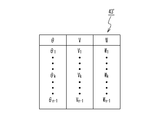
- FIG. 8 shows the data structure of measurement data.
- FIG. 9 shows a data structure of the step determination data according to the first embodiment.
- FIG. 10 is a graph of the step determination data according to the first embodiment.
- FIG. 11 shows the data structure of the control data.
- FIG. 12 is an explanatory diagram illustrating steps for machining a workpiece.
- FIG. 13 is an explanatory diagram illustrating a method for determining a step coordinate range according to the second embodiment of the present invention.
- FIG. 14 shows a data structure of the level difference determination data according to the second embodiment.
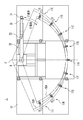
- the machining apparatus 1 As shown in FIG. 1, the machining apparatus 1 according to the first embodiment of the present invention includes a base 10, work support portions 11A to 11I, a rotational direction moving body 20, a servo motor 23, and a radial direction movement. A body 30 and a spindle 31 are provided. The origin O of the cylindrical coordinate system is shown. The moving radius of the cylindrical coordinate system is fixed with respect to the rotational direction moving body 20. The rotational direction moving body 20 turns around the Z axis of a cylindrical coordinate system as a turning axis. Thereby, the rotational direction moving body 20 moves in the rotational direction of the moving radius. The direction of rotation is orthogonal to the radial direction.
- the rotational direction moving body 20 turns in both directions, in which the coordinate ⁇ (declination angle ⁇ ) in the radial rotation direction increases and the direction in which the coordinate ⁇ decreases.
- the radial moving body 30 is supported by the rotational moving body 20 so as to be movable in the radial direction.
- the servo motor 23 drives the radial moving body 30 in the radial direction.
- the radial moving body 30 supports the spindle 31.
- Work support portions 11A to 11I support the work 50A.
- the workpiece 50A has a substantially arc shape.
- the workpiece supporting portions 11A to 11I are arranged and fixed to the base 10 so that the center of curvature of the workpiece 50A substantially coincides with the origin O.
- the processing apparatus 1 processes the workpiece 50A based on the reference surface of the workpiece 50A, strict alignment of the workpiece 50A is not necessary.
- Work support portions 11B to 11E are sequentially arranged counterclockwise from the work support portion 11A (in the direction in which the coordinate ⁇ decreases), and work support portions 11F to 11F in the clockwise direction from the work support portion 11A (in the direction in which the coordinate ⁇ increases). 11I are arranged in order.
- the positions of the work support portions 11B to 11I can be changed along the radial direction with the Z axis as the center.
- a positioning means group 18 is provided on the base 10 corresponding to each of the work support portions 11B to 11I.
- the positioning means group 18 is arranged along a radius centered on the Z axis.
- the positioning means group 18 is, for example, a hole group formed in the base 10, and a female screw is formed in each hole.
- Each of the workpiece support portions 11B to 11I is positioned by a bolt that engages with any one hole included in the corresponding positioning means group 18.
- the workpiece support portions 11B to 11I can be positioned in a wider radial range as they are separated from the workpiece support portion 11A.
- the workpiece support portions 11A to 11I can also support the workpiece 50B having a larger curvature radius than the workpiece 50A.
- the center of curvature of the workpiece 50B is arranged so as to substantially coincide with the fixed point O 'on the cylindrical coordinate system. Strict alignment is not necessary for the workpiece 50B.
- the point O ′ is disposed on a straight line passing through the origin O and the workpiece support portion 11A, and the origin O is disposed between the point O ′ and the workpiece support portion 11A. Therefore, the processing apparatus 1 can process a workpiece having various radii of curvature.
- the machining apparatus 1 includes a servo motor 14, wheels 21, a distance sensor 22, and a tool 32.
- the servo motor 14 drives the rotational direction moving body 20 in the radial rotation direction. That is, the servo motor 14 turns the rotational direction moving body 20 around the Z axis.
- the rotational direction moving body 20 extends in the radial direction from the Z axis passing through the origin O.
- the wheel 21 and the distance sensor 22 are provided in the vicinity of the end of the rotational direction moving body 20 far from the Z axis.
- the wheel 21 travels on the base 10 as the rotational direction moving body 20 turns around the Z axis.
- the spindle 31 is attached to the radial moving body 30 so that the position in the Z-axis direction can be adjusted.
- a tool 32 is attached to the spindle 31. That is, the tool 32 is supported by the radial direction moving body 30.
- the workpiece 50A and the workpiece 50B are represented by the workpiece 50.
- work support parts are provided with the lower side support part 12 arrange
- FIG. The lower support portion 12 and the upper support portion 13 sandwich the work 50.
- Each of the work support parts 11B to 11I includes a lower support part 12 and an upper support part 13 in the same manner as the work support part 11A.
- the work 50 includes a lip flange 52.
- the lip flange surface 52a of the lip flange 52 is a curved surface.
- the distance sensor 22 measures the radial distance to the lip flange surface 52a, which is a reference surface for processing.
- the tool 32 processes the lip portion 51 of the lip flange 52.
- the servo motor 14 and the servo motor 23 control the position of the tool 32 based on the distance measurement result so that the lip portion 51 is processed into a desired dimension.
- the processing device 1 performs trim processing of the lip portion 51.
- the processing apparatus 1 includes a control device 40.
- the control device 40 includes a storage device 41, a calculation device 48, and a numerical control device 49.
- the distance sensor 22 outputs a distance signal indicating the distance to the lip flange surface 52a to the control device 40.
- the computing device 48 generates measurement data 42 based on the distance signal.
- the computing device 48 generates the step determination data 43 based on the measurement data 42.
- the computing device 48 generates control data 44 based on the measurement data 42 and the step determination data 43.
- the storage device 41 stores measurement data 42, level difference determination data 43, and control data 44.
- the numerical controller 49 numerically controls the servo motor 14 and the servo motor 23 based on the control data 44.
- the processing method includes a step of setting a workpiece 50, a step of generating measurement data 42, a step of determining a step coordinate range as a coordinate range in the radial rotation direction of a step formed on the lip flange surface 52a, and a control A step of generating data 44 and a step of machining the workpiece 50 are included.
- the steps for setting the workpiece 50 will be described.
- the radial positions of the workpiece support portions 11B to 11I are adjusted according to the shape of the workpiece 50 to be machined. After the adjustment, the work 50 is set on the work support parts 11A to 11I.
- the numerical controller 49 numerically controls the servo motor 14 so that the rotational direction moving body 20 turns clockwise at a constant peripheral speed.
- the distance sensor 22 emits a laser beam in the radial direction and outputs a distance signal based on the reflected light of the laser beam to the control device 40.
- the value indicated by the distance signal overflows.
- the laser beam is reflected by the lip flange surface 52a for a while after the start of turning, the value indicated by the distance signal does not overflow.
- the control device 40 captures the first value at which the value indicated by the distance signal no longer overflows in association with the coordinate ⁇ 0 at that time. Thereafter, until the value indicated by the distance signal overflows again, the control device 40 takes in the value indicated by the distance signal at that time in association with the coordinate ⁇ at that time each time the value ⁇ increases. Note that a contact type distance sensor may be used instead of the distance sensor 22.
- the distance sensor 22 moves on the locus L22.
- the locus L22 is a circumference having a radius R with the origin O (or Z axis) as the center.
- the distance sensor 22 when the moving radius rotational position of the distance sensor 22 is coordinate theta k, the distance from the distance sensor 22 measures the distance r k of radial to Q k point on the lip flange surface 52a r k Is output to the control device 40.
- the distance sensor 22 when the moving radius rotational position of the distance sensor 22 is coordinate theta k + 1, the distance from the distance sensor 22 measures the radial distance r k + 1 to the point Q k + 1 on the lip flange surface 52a r k + 1 Is output to the control device 40.
- the radial direction of rotation of the coordinates of the point Q k a theta k, the point Q k + 1 of the radial direction of rotation coordinates are ⁇ k + 1.
- the distance sensor 22 has the radial distance r to the points Q 0 to Q n on the lip flange surface 52a, respectively, when the distance sensor 22 is at the positions ⁇ 0 to ⁇ n in the radial rotation direction.
- ⁇ r n measures and outputs the ⁇ r n a distance signal indicating the distance r 0 ⁇ r n to the control unit 40.
- the coordinates in the radial rotation direction of the points Q 0 to Q n are ⁇ 0 to ⁇ n .
- Arithmetic unit 48 based on the distance signal, generates measurement data 42 indicating the relationship between the plurality of points Q 0 ⁇ Q coordinate theta 0 ⁇ moving radius direction of rotation of n theta n and the distance r 0 ⁇ r n.
- the storage device 41 stores measurement data 42.
- a step 53 is formed on the lip flange surface 52a.
- the step 53 is a minute step formed by chemical milling, for example.
- the step 53 is exaggerated and shown in the figure.
- Points Q k + 1 and Q k + 2 are arranged on the step 53.
- the points Q k and Q k + 3 are arranged at portions other than the step 53 of the lip flange surface 52a.
- Distance r k + 1 in the radial direction of rotation of the distance sensor 22 to the point Q k + 1 is different from the distance r k of the moving radius direction of rotation to the point Q k by + [delta] from the distance sensor 22.
- the distance r k + 2 in the radial rotation direction from the distance sensor 22 to the point Q k + 2 is almost the same as the distance r k + 1 in the radial rotation direction from the distance sensor 22 to the point Q k + 1 .
- Distance Distance r k + 3 of the radial direction of rotation of the sensor 22 to the point Q k + 3 is different from the radial direction of rotation of the distance r k + 2 to the point Q k + 2 by - ⁇ from the distance sensor 22.
- FIG. 8 shows the data structure of the measurement data 42.
- the computing device 48 determines a step coordinate range as a coordinate range in the radial rotation direction of the step 53 based on the measurement data 42. For example, the arithmetic device 48 generates the step determination data 43 based on the measurement data 42 and determines the step coordinate range based on the step determination data 43.
- the step determination data 43 indicates the relationship between the distance difference ⁇ r and the coordinate ⁇ of the point Q for each of the points Q 0 to Q n ⁇ 1 .
- the distance difference [Delta] r k is the difference between the radial distance r k + 1 from the distance sensor 22 from radial distance r k and the distance sensor 22 to the point Q k to the point Q k + 1.
- the point Q k + 1 is a point adjacent to the point Q k .
- FIG. 10 is a graph of the step determination data 43.
- the vertical axis represents the distance difference ⁇ r
- the horizontal axis represents the coordinate ⁇ .
- the arithmetic device 48 determines the step coordinate range ⁇ k + 1 to ⁇ k + 2 based on the step determination data 43.
- control data 44 indicates the trajectory of the tool 32.
- the trajectory of the tool 32 is indicated by a combination of the coordinate ⁇ in the radial rotation direction of the tool 32 and the coordinate T in the radial direction.
- R is a radius of the locus L22
- r is a radial distance from the distance sensor 22 to the lip flange surface 52a
- D1 is a predetermined offset value.
- the offset value D1 is the sum of the target width P of the lip 51 and the radius S of the tool 32.
- D2 is an offset value different from D1.
- the offset value D2 is equal to a value obtained by subtracting the correction value ⁇ corresponding to the step 53 from the sum of the target width P of the lip 51 and the radius S of the tool 32.
- the correction value ⁇ is a predetermined value or a calculated value.
- the arithmetic device 48 calculates the increment ⁇ of the distance difference ⁇ r at the start point and the end point of the step 53 based on the step determination data 43, and calculates the correction value ⁇ as a calculated value based on the increment ⁇ of the distance difference ⁇ r.
- FIG. 12 shows the relationship between coordinates T, distance r, offset value D, target width P, and radius S.
- the numerical controller 49 numerically controls the servo motor 14 and the servo motor 23 based on the control data 44 and moves the tool 32 along a locus L32 indicated by the control data 44.
- the control data 44 indicates coordinates ( ⁇ k , T k ), ( ⁇ k + 1 , T k + 1 ) and the like of the points U k and U k + 1 on the locus L32. Thereby, the trim processing of the lip part 51 is performed.
- the first locus portion of the locus L32 in which the coordinate in the radial rotation direction is not included in the step coordinate range ⁇ k + 1 to ⁇ k + 2 (the portion of the radial rotation direction coordinate is ⁇ 0 to ⁇ k and the portion of ⁇ k + 3 to ⁇ n ) is calculated using the offset value D1
- the moving radius direction of rotation of the coordinate step coordinate range ⁇ k + 1 ⁇ ⁇ k + second trajectory part (moving radius direction of rotation coordinates theta k + 1 included in the 2 ⁇ theta k + 2 of the locus L32 ) Is calculated using the offset value D2, so that the shape of the step 53 is prevented from being reflected on the contour line 51a of the lip 51 formed by the tool 32.
- the numerical controller 49 controls the servo motor 14 so that the tool 32 moves counterclockwise. Since the turning direction of the rotational direction moving body 20 when generating the measurement data 42 and the turning direction of the rotational direction moving body 20 when machining the workpiece 50 are opposite to each other, man-hours are reduced.
- the numerical controller 49 numerically controls the servo motor 14 and the servo motor 23 so that the tool 32 passes through the point U x having the coordinate ⁇ x in the radial rotation direction between the coordinates ⁇ k and the coordinates ⁇ k + 1 .
- the control data 44 does not indicate the coordinates ( ⁇ x , T x ) of the point U x .
- the step 53 is one step, and the increment of the distance difference ⁇ r at the start point of the step 53 is equal to the increment of the distance difference ⁇ r at the end point.
- the processing apparatus 1 can also be applied when the step 53 is a plurality of steps, or when the increment of the distance difference ⁇ r at the start point of the step 53 is different from the increment of the distance difference ⁇ r at the end point.
- the machining direction according to the second embodiment of the present invention is the same as the machining method according to the first embodiment except for the step of determining the step coordinate range.
- the points Q k ⁇ 1 , Q k , Q k + 3 , and Q k + 4 are arranged at portions other than the step 53 of the lip flange surface 52a.
- the points Q k + 1 and Q k + 2 are arranged at the step 53.
- the radial distance from the distance sensor 22 to the virtual point Q ′ k + 1 is measured instead of the radial distance from the distance sensor 22 to the point Q k + 1. Is measured.
- the distance V k + 3 between the center of the circle C k + 3 passing through three consecutive points Q k + 2 to Q k + 4 including the point Q k + 2 arranged at the step 53 and the origin O or the point O ′ is large, and the radius of the circle C k + 3 W k + 3 is much smaller than the radius of curvature of the lip flange surface 52a.
- FIG. 14 shows step determination data 43 ′ generated by the arithmetic device 48 based on the measurement data 42.
- the level difference determination data 43 ′ is the distance between the coordinate ⁇ of the point Q and the center of the circle C passing through three consecutive points including the point Q and the origin O or the point O ′.
- the relationship between V and the radius W of the circle C is shown.
- the distance V k is the distance between the center and the origin O or the point O 'of the circle C k passing through three points Q k-1 ⁇ Q k + 1 consecutive including the point Q k.
- the radius W k is the radius of the circle C k .
- the computing device 48 can determine the step coordinate range ⁇ k + 1 to ⁇ k + 2 based on the step determination data 43 ′. Determine the step coordinate range based only on the radius of a circle passing through three consecutive points, or determine the step coordinate range based only on the distance between the center of a circle passing through three consecutive points and a predetermined point O or O ′ However, it is preferable to determine the step coordinate range based on both the radius of the circle and the distance between the center of the circle and a predetermined point.
- the case where the shape of the lip flange surface 52a is grasped based on the plane polar coordinate system and the tool 32 is moved based on the plane polar coordinate system has been described. Processing based on such a plane polar coordinate system is suitable when the lip flange surface 52a is a curved surface.
- the curvature radius of the lip flange surface 52a is very large (for example, when the workpiece 50 has a linear shape)
- the shape of the lip flange surface 52a is grasped based on the XY coordinate system, and the tool 32 is moved based on the XY coordinate system. It is preferable to move.
- the servo motor 14 drives the rotational direction moving body 20 in the X direction
- the servo motor 23 drives the radial direction moving body 30 in the Y direction with respect to the rotational direction moving body 20
- the distance sensor 22 is in the Y direction. Measure the distance.
- processing methods according to the first and second embodiments can be applied to various machining processes other than trim processing.
Abstract
第1サーボモータは第1部分を動径回転方向に駆動する。第2部分は、動径方向に移動自在に第1部分に支持される。第2サーボモータは第2部分を動径方向に駆動する。第2部分は、ワークを加工する工具を支持する。制御装置は、距離センサからの距離信号に基づいて、ワークの基準面上の複数点の動径回転方向の座標と距離センサまでの動径方向距離との関係を示す測定データを生成し、測定データに基づいて基準面に形成された段差の動径回転方向の座標範囲を判定し、測定データ及び段差の座標範囲に基づいて工具の軌跡を示す制御データを生成し、制御データに基づいて第1及び第2サーボモータを数値制御する。制御装置は、制御データを生成する際に、段差の座標範囲に基づいて複数のオフセット値を使いわける。
Description
本発明は、機械加工を行うための加工装置及び加工方法に関し、特にプリプロセス計測に基づいて工具経路を設定することにより、高精度の加工を行う加工装置及び加工方法に関する。
航空機の板金部品や複合材料部品は、所定の形状に成形された後、図面で指定された正規寸法となるようにトリム加工が行われる。トリム加工方法として、専用の治具を用いて部品にケガキ線を入れ、ケガキ線に沿ってトリム加工を行う方法、部品に固定された専用のガイド治具に沿って工具を移動させてトリム加工を行う方法、NC(数値制御)加工装置を用いてトリム加工を行う方法が知られている。ケガキ線に沿ってトリム加工を行う方法は、自動化が困難である。部品に固定された専用のガイド治具に沿って工具を移動させてトリム加工を行う方法では、部品ごとに専用の治具が必要であり、且つ、治具を部品に取り付けるときの位置合わせを厳密に行う必要がある。NC加工装置を用いてトリム加工を行う方法においても、部品の位置合わせを厳密に行う必要がある。
特開2005-342865号公報は、部品の形状に倣うトリム加工を行うための加工装置を開示している。加工装置は、被加工材のトリム加工を行う工具と、ガイド治具とを備える。ガイド治具は、当接部と、当接部に取り付けられた保持部とを備える。保持部は、工具を保持する。当接部は、被加工材の長手方向に延びる基準面に当接する当接面を備え、当接面が基準面に当接した状態で長手方向に移動する。工具は、基準面の形状に対応する軌跡に沿って移動して被加工材にトリム形状を形成する。部品の形状に倣うトリム加工によれば、厳密な位置合わせは不要である。
しかしながら、基準面の有する形状がそのままトリム形状に反映されるため、基準面に凹凸が設けられている場合には、その凹凸に対応する凹凸がトリム形状に設けられる。基準面の凹凸が必要であり、トリム形状の凹凸が不要である場合、部品の形状に倣うトリム加工におけるこのような融通の利かなさが問題になる。
特開平11-123634号公報は、部品の形状に倣うトリム加工を行うための他の加工装置を開示している。加工装置は、加工用工具部と、数値制御部と、計測手段と、工具経路導出手段とを備える。計測手段は、数値制御部により駆動制御されて被加工物の寸法分布を測定する。工具経路導出手段は、計測手段の計測結果に基づいて、工具経路を導出する。数値制御部は、加工用工具部を工具経路に沿って移動させる。
本発明の目的は、ワークの厳密な位置合わせが不要であり、且つ、ワークが所望の形状に加工される加工装置及び加工方法を提供することである。
本発明の第1の観点による加工装置は、第1部分と、前記第1部分を第1方向に駆動する第1サーボモータと、前記第1部分に設けられた距離センサと、前記第1方向に直交する第2方向に移動自在に前記第1部分に支持される第2部分と、前記第2部分を前記第2方向に駆動する第2サーボモータと、制御装置とを具備する。前記第2部分は、ワークを加工する工具を支持する。前記距離センサは、前記距離センサが前記第1方向の複数位置の各々にあるときに、前記ワークの基準面までの前記第2方向の距離を測定して前記距離を示す距離信号を出力する。前記制御装置は、前記距離信号に基づいて前記基準面上の複数点の前記第1方向の座標と前記距離センサまでの距離との関係を示す測定データを生成し、前記測定データに基づいて前記基準面に形成された段差の前記第1方向の座標範囲としての段差座標範囲を判定し、前記測定データ及び前記段差座標範囲に基づいて前記工具の軌跡を示す制御データを生成し、前記制御データに基づいて前記第1サーボモータ及び前記第2サーボモータを数値制御する。前記軌跡は、前記第1方向の座標が前記段差座標範囲に含まれない第1軌跡部分と、前記第1方向の座標が前記段差座標範囲に含まれる第2軌跡部分とを含む。前記制御装置は、第1オフセット値に基づいて前記制御データの前記第1軌跡部分に対応する部分を計算し、第2オフセット値に基づいて前記制御データの前記第2軌跡部分に対応する部分を計算する。
好ましくは、前記基準面は湾曲面であり、前記第2方向は動径方向であり、前記第1方向は前記動径の回転方向である。
好ましくは、加工装置は、前記ワークを支持する第1ワーク支持部と、前記ワークを支持する第2ワーク支持部と、前記第1ワーク支持部及び前記第2ワーク支持部が固定されるベースとを更に具備する。前記第1サーボモータは、前記第1部分を旋回軸まわりに旋回する。前記ベースに前記第1ワーク支持部を位置決めするための第1位置決め手段群と前記第2ワーク支持部を位置決めするための第2位置決め手段群とが設けられる。前記第1位置決め手段群は、前記旋回軸を中心とする第1半径に沿って配置される。前記第2位置決め手段群は、前記旋回軸を中心とする第2半径に沿って配置される。
好ましくは、前記制御データは、前記軌跡上の点Ukの前記第1方向の座標θkと、前記点Ukの前記第2方向の座標Tkと、前記軌跡上の点Uk+1の前記第1方向の座標θk+1と、前記点Uk+1の前記第2方向の座標Tk+1とを示す。前記制御装置は、前記工具が前記座標θk及び前記座標θk+1の間の前記第1方向の座標θxを持つ点Uxを通るように前記第1サーボモータ及び前記第2サーボモータを制御する。前記点Uxの前記第2方向の座標Txは、式:
Tx=Tk+{(θx-θk)/(θk+1-θk)}・(Tk+1-Tk)
を満たす。
Tx=Tk+{(θx-θk)/(θk+1-θk)}・(Tk+1-Tk)
を満たす。
好ましくは、前記制御装置は、前記測定データに基づいて段差判定データを生成し、前記段差判定データに基づいて前記段差座標範囲を判定する。前記段差判定データは、前記複数点の一つとしての注目点について、前記距離センサから前記注目点までの前記第2方向の距離と前記距離センサから前記複数点のうちの前記注目点の隣の点までの前記第2方向の距離の差分と、前記注目点の前記第1方向の座標との関係を示す。
好ましくは、前記制御装置は、前記測定データに基づいて段差判定データを生成し、前記段差判定データに基づいて前記段差座標範囲を判定する。前記段差判定データは、前記複数点の一つとしての注目点について、前記複数点のうちの前記注目点を含む連続する3点を通る円の半径と前記注目点の前記第1方向の座標との関係を示す。
好ましくは、前記制御装置は、前記測定データに基づいて段差判定データを生成し、前記段差判定データに基づいて前記段差座標範囲を判定する。前記段差判定データは、前記複数点の一つとしての注目点について、前記複数点のうちの前記注目点を含む連続する3点を通る円の中心と所定の点との距離と前記注目点の前記第1方向の座標との関係を示す。
好ましくは、前記制御装置は、前記測定データに基づいて段差判定データを生成し、前記段差判定データに基づいて前記段差座標範囲を判定する。前記段差判定データは、前記複数点の一つとしての注目点について、前記複数点のうちの前記注目点を含む連続する3点を通る円の半径と前記注目点の前記第1方向の座標との関係を示し、前記円の中心と所定の点との距離と前記注目点の前記第1方向の座標との関係を示す。
本発明の第2の観点による加工方法は、第1サーボモータによって第1方向に駆動される第1部分に設けられた距離センサが、前記第1方向の複数位置の各々にあるときに、ワークの基準面までの前記第1方向に直交する第2方向の距離を測定して前記距離を示す距離信号を出力するステップと、前記距離信号に基づいて前記基準面上の複数点の前記第1方向の座標と前記距離センサまでの距離との関係を示す測定データを生成するステップと、前記測定データに基づいて前記基準面に形成された段差の前記第1方向の座標範囲としての段差座標範囲を判定するステップと、前記測定データ及び前記段差座標範囲に基づいて前記ワークを加工する工具の軌跡を示す制御データを生成するステップと、前記制御データに基づいて前記第1サーボモータ及び第2サーボモータを数値制御するステップとを具備する。前記工具は、第2部分に支持される。前記第2部分は、前記第2方向に移動自在に前記第1部分に支持される。前記第2部分は前記第2サーボモータによって前記第2方向に駆動される。前記軌跡は、前記第1方向の座標が前記段差座標範囲に含まれない第1軌跡部分と、前記第1方向の座標が前記段差座標範囲に含まれる第2軌跡部分とを含む。前記段差座標範囲を判定するステップは、第1オフセット値に基づいて前記制御データの前記第1軌跡部分に対応する部分を計算するステップと、第2オフセット値に基づいて前記制御データの前記第2軌跡部分に対応する部分を計算するステップとを備える。
好ましくは、前記基準面は湾曲面であり、前記第2方向は動径方向であり、前記第1方向は前記動径の回転方向である。
好ましくは、前記第1サーボモータは、前記第1部分を旋回軸まわりに旋回する。加工方法は、前記ワークを支持すべき第1ワーク支持部の前記旋回軸を中心とする第1半径方向の位置を調節するステップと、前記ワークを支持すべき第2ワーク支持部の前記旋回軸を中心とする第2半径方向の位置を調節するステップとを更に具備する。
好ましくは、前記制御データは、前記軌跡上の点Ukの前記第1方向の座標θkと、前記点Ukの前記第2方向の座標Tkと、前記軌跡上の点Uk+1の前記第1方向の座標θk+1と、前記点Uk+1の前記第2方向の座標Tk+1とを示す。前記第1サーボモータ及び前記第2サーボモータを数値制御する前記ステップは、前記工具が前記座標θk及び前記座標θk+1の間の前記第1方向の座標θxを持つ点Uxを通るように前記第1サーボモータ及び前記第2サーボモータを数値制御するステップを含む。前記点Uxの前記第2方向の座標Txは、式:
Tx=Tk+{(θx-θk)/(θk+1-θk)}・(Tk+1-Tk)
を満たす。
Tx=Tk+{(θx-θk)/(θk+1-θk)}・(Tk+1-Tk)
を満たす。
好ましくは、前記段差座標範囲を判定する前記ステップは、前記測定データに基づいて段差判定データを生成するステップと、前記段差判定データに基づいて前記段差座標範囲を判定するステップとを備える。前記段差判定データは、前記複数点の一つとしての注目点について、前記距離センサから前記注目点までの前記第2方向の距離と前記距離センサから前記複数点のうちの前記注目点の隣の点までの前記第2方向の距離の差分と、前記注目点の前記第1方向の座標との関係を示す。
好ましくは、前記段差座標範囲を判定する前記ステップは、前記測定データに基づいて段差判定データを生成するステップと、前記段差判定データに基づいて前記段差座標範囲を判定するステップとを備える。前記段差判定データは、前記複数点の一つとしての注目点について、前記複数点のうちの前記注目点を含む連続する3点を通る円の半径と前記注目点の前記第1方向の座標との関係を示す。
好ましくは、前記段差座標範囲を判定する前記ステップは、前記測定データに基づいて段差判定データを生成するステップと、前記段差判定データに基づいて前記段差座標範囲を判定するステップとを備える。前記段差判定データは、前記複数点の一つとしての注目点について、前記複数点のうちの前記注目点を含む連続する3点を通る円の中心と所定の点との距離と前記注目点の前記第1方向の座標との関係を示す。
好ましくは、前記段差座標範囲を判定する前記ステップは、前記測定データに基づいて段差判定データを生成するステップと、前記段差判定データに基づいて前記段差座標範囲を判定するステップとを備える。前記段差判定データは、前記複数点の一つとしての注目点について、前記複数点のうちの前記注目点を含む連続する3点を通る円の半径と前記注目点の前記第1方向の座標との関係を示し、前記円の中心と所定の点との距離と前記注目点の前記第1方向の座標との関係を示す。
本発明によれば、ワークの厳密な位置合わせが不要であり、且つ、ワークが所望の形状に加工される加工装置及び加工方法が提供される。
本発明の上記目的、他の目的、効果、及び特徴は、添付される図面と連携して実施の形態の記述から、より明らかになる。
添付図面を参照して、本発明による加工装置及び加工方法を実施するための形態を以下に説明する。
(第1の実施形態)
図1に示すように、本発明の第1の実施形態に係る加工装置1は、ベース10と、ワーク支持部11A~11Iと、回転方向移動体20と、サーボモータ23と、動径方向移動体30と、スピンドル31を備える。円柱座標系の原点Oが示されている。円柱座標系の動径は回転方向移動体20に対して固定されている。回転方向移動体20は、旋回軸としての円柱座標系のZ軸まわりに旋回する。これにより、回転方向移動体20は、動径の回転方向に移動する。回転方向は、動径方向に直交する。回転方向移動体20は、動径回転方向の座標θ(偏角θ)が増加する向きと、座標θが減少する向きとの双方向とに旋回する。動径方向移動体30は、動径方向に移動自在に回転方向移動体20に支持される。サーボモータ23は、動径方向移動体30を動径方向に駆動する。動径方向移動体30は、スピンドル31を支持する。
図1に示すように、本発明の第1の実施形態に係る加工装置1は、ベース10と、ワーク支持部11A~11Iと、回転方向移動体20と、サーボモータ23と、動径方向移動体30と、スピンドル31を備える。円柱座標系の原点Oが示されている。円柱座標系の動径は回転方向移動体20に対して固定されている。回転方向移動体20は、旋回軸としての円柱座標系のZ軸まわりに旋回する。これにより、回転方向移動体20は、動径の回転方向に移動する。回転方向は、動径方向に直交する。回転方向移動体20は、動径回転方向の座標θ(偏角θ)が増加する向きと、座標θが減少する向きとの双方向とに旋回する。動径方向移動体30は、動径方向に移動自在に回転方向移動体20に支持される。サーボモータ23は、動径方向移動体30を動径方向に駆動する。動径方向移動体30は、スピンドル31を支持する。
ワーク支持部11A~11Iは、ワーク50Aを支持する。ワーク50Aは、略円弧形状を有する。ワーク支持部11A~11Iは、ワーク50Aの曲率中心が原点Oにおおよそ一致するように配置されてベース10に固定される。なお、加工装置1がワーク50Aの基準面に基づいてワーク50Aを加工するため、ワーク50Aの厳密な位置合わせは不要である。ワーク支持部11Aから反時計回り(座標θが減少する方向)にワーク支持部11B~11Eが順番に配置され、ワーク支持部11Aから時計回り(座標θが増加する方向)にワーク支持部11F~11Iが順番に配置される。ワーク支持部11B~11Iは、それぞれ、Z軸を中心とする半径方向に沿って位置を変更可能である。ワーク支持部11B~11Iの各々に対応して、位置決め手段群18がベース10に設けられている。位置決め手段群18は、Z軸を中心とする半径に沿って配置されている。位置決め手段群18は、例えば、ベース10に形成された穴群であり、その各穴に雌ネジが形成されている。ワーク支持部11B~11Iの各々は、対応する位置決め手段群18に含まれる任意の一つの穴と係合するボルトによって位置決めされる。ワーク支持部11B~11Iは、ワーク支持部11Aから離れているほど、半径方向の広い範囲で位置決め可能である。したがって、ワーク支持部11A~11Iは、ワーク50Aより曲率半径が大きいワーク50Bも支持することが可能である。この場合、ワーク50Bの曲率中心は、円柱座標系上の定点O’におおよそ一致するように配置される。ワーク50Bについても厳密な位置合わせは不要である。例えば、点O’は原点O及びワーク支持部11Aを通る直線上に配置され、原点Oが点O’及びワーク支持部11Aの間に配置される。したがって、加工装置1は、様々な曲率半径のワークを加工することが可能である。
図2を参照して、加工装置1は、サーボモータ14と、車輪21と、距離センサ22と、工具32を備える。サーボモータ14は、回転方向移動体20を動径回転方向に駆動する。すなわち、サーボモータ14は、回転方向移動体20をZ軸まわりに旋回する。回転方向移動体20は、原点Oを通るZ軸から動径方向に延びている。車輪21及び距離センサ22は、回転方向移動体20のZ軸から遠い方の端部近傍に設けられている。車輪21は、回転方向移動体20のZ軸まわりの旋回に伴ってベース10上を走行する。スピンドル31は、Z軸方向の位置が調節可能なように動径方向移動体30に取り付けられている。スピンドル31に工具32が取り付けられる。すなわち、工具32は、動径方向移動体30に支持される。ワーク50A及びワーク50Bがワーク50で代表されている。ワーク支持部11Aは、ワーク50の下側に配置される下側支持部12と、ワーク50の上側に配置される上側支持部13を備える。下側支持部12及び上側支持部13は、ワーク50を挟む。ワーク支持部11B~11Iの各々も、ワーク支持部11Aと同様に下側支持部12及び上側支持部13を備える。
図3を参照して、ワーク50は、リップフランジ52を備える。リップフランジ52のリップフランジ面52aは、湾曲面である。ワーク50がワーク50Aの場合にリップフランジ面52aの曲率中心は原点Oにおおよそ一致し、ワーク50がワーク50Bの場合にリップフランジ面52aの曲率中心は点O’におおよそ一致する。距離センサ22は、加工のための基準面であるリップフランジ面52aまでの動径方向の距離を測定する。工具32は、リップフランジ52のリップ部51を加工する。サーボモータ14及びサーボモータ23は、リップ部51が所望の寸法に加工されるように、距離の測定結果に基づいて工具32の位置を制御する。加工装置1は、リップ部51のトリム加工を実行する。
図4を参照して、加工装置1が備える制御系を説明する。加工装置1は、制御装置40を備える。制御装置40は記憶装置41と、演算装置48と、数値制御装置49を備える。距離センサ22は、リップフランジ面52aまでの距離を示す距離信号を制御装置40に出力する。演算装置48は、距離信号に基づいて測定データ42を生成する。演算装置48は、測定データ42に基づいて段差判定データ43を生成する。演算装置48は、測定データ42及び段差判定データ43に基づいて制御データ44を生成する。記憶装置41は、測定データ42、段差判定データ43、及び制御データ44を記憶する。数値制御装置49は、制御データ44に基づいてサーボモータ14及びサーボモータ23を数値制御する。
以下、加工装置1を用いた加工方法を説明する。加工方法は、ワーク50をセットするステップと、測定データ42を生成するステップと、リップフランジ面52aに形成された段差の動径回転方向の座標範囲としての段差座標範囲を判定するステップと、制御データ44を生成するステップと、ワーク50を加工するステップとを含む。
はじめに、ワーク50をセットするステップを説明する。ワーク支持部11B~ワーク支持部11Iの半径方向位置を加工すべきワーク50の形状に合わせて調節する。調節が済んだら、ワーク支持部11A~11Iにワーク50をセットする。
図5を参照して、測定データ42を生成するステップを説明する。数値制御装置49は、回転方向移動体20が一定周速度で時計回りに旋回するように、サーボモータ14を数値制御する。回転方向移動体20の旋回中、距離センサ22は、レーザー光線を動径方向に出射し、このレーザー光線の反射光に基づく距離信号を制御装置40に出力する。回転方向移動体20の旋回の開始直後は、距離信号が示す値がオーバーフローする。旋回開始から暫くたってレーザー光線がリップフランジ面52aで反射されるようになると、距離信号が示す値がオーバーフローしなくなる。制御装置40は、距離信号が示す値がオーバーフローしなくなった最初の値をそのときの座標θ0と対応付けて取り込む。その後、制御装置40は、距離信号が示す値が再びオーバーフローするまで、座標θがΔθ増加するごとにそのときの距離信号が示す値をそのときの座標θと対応付けて取り込む。なお、距離センサ22のかわりに接触式の距離センサを用いることも可能である。
図6を参照して、回転方向移動体20が旋回すると、距離センサ22は軌跡L22上を移動する。軌跡L22は、原点O(又はZ軸)を中心とする半径Rの円周である。距離センサ22は、距離センサ22の動径回転方向位置が座標θkのとき、距離センサ22からリップフランジ面52a上の点Qkまでの動径方向の距離rkを測定して距離rkを示す距離信号を制御装置40に出力する。距離センサ22は、距離センサ22の動径回転方向位置が座標θk+1のとき、距離センサ22からリップフランジ面52a上の点Qk+1までの動径方向の距離rk+1を測定して距離rk+1を示す距離信号を制御装置40に出力する。点Qkの動径回転方向の座標はθkであり、点Qk+1の動径回転方向の座標はθk+1である。このように、距離センサ22は、距離センサ22が動径回転方向の位置θ0~θnにあるとき、それぞれ、リップフランジ面52a上の点Q0~Qnまでの動径方向の距離r0~rnを測定して距離r0~rnを示す距離信号を制御装置40に出力する。ここで、点Q0~Qnの動径回転方向の座標はθ0~θnである。演算装置48は、距離信号に基づいて、複数点Q0~Qnの動径回転方向の座標θ0~θnと距離r0~rnとの関係を示す測定データ42を生成する。記憶装置41は測定データ42を記憶する。
図7を参照して、リップフランジ面52aには、段差53が形成されている。段差53は、例えば、ケミカルミリングにより形成された微小な段差である。段差53は誇張されて図に示されている。点Qk+1及びQk+2は、段差53上に配置される。点Qk及びQk+3は、リップフランジ面52aの段差53以外の部分に配置される。距離センサ22から点Qk+1までの動径回転方向の距離rk+1は、距離センサ22から点Qkまでの動径回転方向の距離rkから+δだけ異なっている。距離センサ22から点Qk+2までの動径回転方向の距離rk+2は、距離センサ22から点Qk+1までの動径回転方向の距離rk+1とほとんど同じである。距離センサ22から点Qk+3までの動径回転方向の距離rk+3は、距離センサ22から点Qk+2までの動径回転方向の距離rk+2から-δだけ異なっている。
図8は、測定データ42のデータ構造を示している。
次に段差53の動径回転方向の座標範囲としての段差座標範囲を判定するステップを説明する。演算装置48は、測定データ42に基づいて段差53の動径回転方向の座標範囲としての段差座標範囲を判定する。例えば、演算装置48は、測定データ42に基づいて段差判定データ43を生成し、段差判定データ43に基づいて段差座標範囲を判定する。
図9を参照して、段差判定データ43を説明する。段差判定データ43は、点Q0~Qn-1の各々について、距離差分Δrと点Qの座標θとの関係を示す。ここで距離差分Δrkは、距離センサ22から点Qkまでの動径方向の距離rkと距離センサ22から点Qk+1までの動径方向の距離rk+1との差分である。点Qk+1は点Qkの隣の点である。
図10は、段差判定データ43のグラフである。図10において、縦軸は距離差分Δrを示し、横軸は座標θを示す。図10から明らかなように、δが非常に小さい場合であっても、段差53の始点及び終点が容易に検出される。したがって、段差判定データ43に基づいて段差座標範囲を判定することは容易である。演算装置48は、段差判定データ43に基づいて、段差座標範囲θk+1~θk+2を判定する。
図11を参照して、制御データ44を生成するステップを説明する。演算装置48は、測定データ42及び段差座標範囲θk+1~θk+2に基づいて、制御データ44を生成する。制御データ44は工具32の軌跡を示す。工具32の軌跡は、工具32の動径回転方向の座標θと動径方向の座標Tとの組み合わせで示されている。
動径回転方向の座標θ0~θk及びθk+3~θnが段差座標範囲θk+1~θk+2に含まれないため、演算装置48は式:
T=R+r+D1
に基づいて座標θ0~θkに対応する座標T0~Tkと座標θk+3~θnに対応する座標Tk+3~Tnとを計算する。ここで、Rは軌跡L22の半径、rは距離センサ22からリップフランジ面52aまでの動径方向距離、D1は所定のオフセット値である。オフセット値D1は、リップ部51の目標幅Pと工具32の半径Sの和である。例えば、動径回転方向の座標θkに対応する動径方向座標Tkは、式:
Tk=R+rk+D1=R+rk+P+S
で与えられる。
T=R+r+D1
に基づいて座標θ0~θkに対応する座標T0~Tkと座標θk+3~θnに対応する座標Tk+3~Tnとを計算する。ここで、Rは軌跡L22の半径、rは距離センサ22からリップフランジ面52aまでの動径方向距離、D1は所定のオフセット値である。オフセット値D1は、リップ部51の目標幅Pと工具32の半径Sの和である。例えば、動径回転方向の座標θkに対応する動径方向座標Tkは、式:
Tk=R+rk+D1=R+rk+P+S
で与えられる。
動径回転方向の座標θk+1及びθk+2が段差座標範囲θk+1~θk+2に含まれるため、演算装置48は式:
T=R+r+D2
に基づいて座標θk+1に対応する座標Tk+1と座標θk+2に対応する座標Tk+2とを計算する。ここで、D2はD1と異なるオフセット値である。オフセット値D2は、リップ部51の目標幅Pと工具32の半径Sの和から段差53に対応する補正値εを引いた値に等しい。補正値εは、所定値又は計算値である。演算装置48は、例えば、段差判定データ43に基づいて段差53の始点や終点における距離差分Δrの増分δを計算し、距離差分Δrの増分δに基づいて計算値としての補正値εを計算する。例えば、動径回転方向の座標θk+1に対応する動径方向座標Tk+1は、式:
Tk+1=R+rk+1+D2=R+rk+1+P+S-ε
で与えられる。
図12は、座標T、距離r、オフセット値D、目標幅P、及び半径Sの関係を示している。
図12を参照して、ワーク50を加工するステップを説明する。数値制御装置49は、制御データ44に基づいてサーボモータ14及びサーボモータ23を数値制御して、工具32を制御データ44が示す軌跡L32に沿って移動する。制御データ44は、軌跡L32上の点Uk、Uk+1等の座標(θk,Tk)、(θk+1,Tk+1)等を示す。これにより、リップ部51のトリム加工が行われる。軌跡L32のうち動径回転方向の座標が段差座標範囲θk+1~θk+2に含まれない第1軌跡部分(動径回転方向の座標がθ0~θkの部分とθk+3~θnの部分)がオフセット値D1を用いて計算され、軌跡L32のうち動径回転方向の座標が段差座標範囲θk+1~θk+2に含まれる第2軌跡部分(動径回転方向の座標がθk+1~θk+2の部分)がオフセット値D2を用いて計算されるため、工具32によって形成されるリップ部51の輪郭線51aに段差53の形状が反映されることが防がれる。
このとき、数値制御装置49は工具32が反時計回りに移動するようにサーボモータ14を制御する。測定データ42を生成するときの回転方向移動体20の旋回方向とワーク50を加工するときの回転方向移動体20の旋回方向が互いに逆方向であるため、工数が削減される。
更に、数値制御装置49は、工具32が座標θk及び座標θk+1の間の動径回転方向の座標θxを持つ点Uxを通るようにサーボモータ14及びサーボモータ23を数値制御する。制御データ44は点Uxの座標(θx,Tx)を示していない。点Uxの動径方向の座標Txは、式:
Tx=Tk+{(θx-θk)/(θk+1-θk)}・(Tk+1-Tk)
を満たす。このような線形補間制御が実行されるため、輪郭線51aが滑らかになる。
Tx=Tk+{(θx-θk)/(θk+1-θk)}・(Tk+1-Tk)
を満たす。このような線形補間制御が実行されるため、輪郭線51aが滑らかになる。
上述の説明においては、段差53が一段の段差であり、段差53の始点における距離差分Δrの増分の大きさと終点における距離差分Δrの増分の大きさとが等しい。加工装置1は、段差53が複数段の段差である場合や、段差53の始点における距離差分Δrの増分の大きさと終点における距離差分Δrの増分の大きさとが異なる場合にも適用可能である。
(第2の実施形態)
本発明の第2の実施形態に係る加工方向は、段差座標範囲を判定するステップを除いて第1の実施形態に係る加工方法と同じである。
本発明の第2の実施形態に係る加工方向は、段差座標範囲を判定するステップを除いて第1の実施形態に係る加工方法と同じである。
図13を参照して、本実施形態に係る段差座標範囲を判定するステップを説明する。点Qk-1、Qk、Qk+3、及びQk+4は、リップフランジ面52aの段差53以外の部分に配置される。点Qk+1及びQk+2は、段差53に配置される。リップフランジ面52aに段差53が形成されていない場合、距離センサ22から点Qk+1までの動径方向距離が測定されるかわりに距離センサ22から仮想的な点Q’k+1までの動径方向距離が測定される。3点Qk-1、Qk、Q’k+1を通る円C’kの中心と原点O又は点O’との距離V’kは小さく、円C’kの半径W’kはリップフランジ面52aの曲率半径とほぼ同じである。これに対し、段差53に配置された点Qk+1を含む連続する3点Qk-1~Qk+1を通る円Ckの中心と原点O又は点O’との距離Vkは大きく、円Ckの半径Wkはリップフランジ面52aの曲率半径よりずっと小さい。同様に、段差53に配置された点Qk+2を含む連続する3点Qk+2~Qk+4を通る円Ck+3の中心と原点O又は点O’との距離Vk+3は大きく、円Ck+3の半径Wk+3はリップフランジ面52aの曲率半径よりずっと小さい。
図14は、演算装置48が測定データ42に基づいて生成する段差判定データ43’を示す。段差判定データ43’は、点Q1~Qn-1の各々について、点Qの座標θと、点Qを含む連続する3点を通る円Cの中心と原点O又は点O’との距離Vと、円Cの半径Wとの関係を示す。例えば、距離Vkは、点Qkを含む連続する3点Qk-1~Qk+1を通る円Ckの中心と原点O又は点O’との距離である。半径Wkは、円Ckの半径である。演算装置48は、段差判定データ43’に基づいて段差座標範囲θk+1~θk+2を判定することが可能である。連続する3点を通る円の半径だけに基づいて段差座標範囲を判定したり連続する3点を通る円の中心と所定の点O又はO’の距離だけに基づいて段差座標範囲を判定したりすることも可能であるが、円の半径と円の中心と所定の点の距離との両方に基づいて段差座標範囲を判定することが好ましい。
第1及び第2の実施形態において、平面極座標系に基づいてリップフランジ面52aの形状を把握し、平面極座標系に基づいて工具32を移動する場合を説明した。このような平面極座標系に基づく加工は、リップフランジ面52aが湾曲面の場合に好適である。一方、リップフランジ面52aの曲率半径が非常に大きい場合(例えばワーク50が直線形状の場合)、XY座標系に基づいてリップフランジ面52aの形状を把握し、XY座標系に基づいて工具32を移動することが好ましい。この場合、サーボモータ14は回転方向移動体20をX方向に駆動し、サーボモータ23は動径方向移動体30を回転方向移動体20に対してY方向に駆動し、距離センサ22はY方向の距離を測定する。
また、第1及び第2の実施形態による加工方法は、トリム加工以外の様々な機械加工にも適用可能である。
以上、実施の形態を参照して本発明を説明したが、本発明は上記実施の形態に限定されるものではない。上記実施の形態に様々な変更を行うことが可能である。
この出願は、2009年2月27日に出願された日本出願特願2009-045253号を基礎とする優先権を主張し、その開示の全てをここに取り込む。
Claims (16)
- 第1部分と、
前記第1部分を第1方向に駆動する第1サーボモータと、
前記第1部分に設けられた距離センサと、
前記第1方向に直交する第2方向に移動自在に前記第1部分に支持される第2部分と、
前記第2部分を前記第2方向に駆動する第2サーボモータと、
制御装置と
を具備し、
前記第2部分は、ワークを加工する工具を支持し、
前記距離センサは、前記距離センサが前記第1方向の複数位置の各々にあるときに、前記ワークの基準面までの前記第2方向の距離を測定して前記距離を示す距離信号を出力し、
前記制御装置は、
前記距離信号に基づいて前記基準面上の複数点の前記第1方向の座標と前記距離センサまでの距離との関係を示す測定データを生成し、
前記測定データに基づいて前記基準面に形成された段差の前記第1方向の座標範囲としての段差座標範囲を判定し、
前記測定データ及び前記段差座標範囲に基づいて前記工具の軌跡を示す制御データを生成し、
前記制御データに基づいて前記第1サーボモータ及び前記第2サーボモータを数値制御し、
前記軌跡は、前記第1方向の座標が前記段差座標範囲に含まれない第1軌跡部分と、前記第1方向の座標が前記段差座標範囲に含まれる第2軌跡部分とを含み、
前記制御装置は、第1オフセット値に基づいて前記制御データの前記第1軌跡部分に対応する部分を計算し、第2オフセット値に基づいて前記制御データの前記第2軌跡部分に対応する部分を計算する
加工装置。 - 前記基準面は湾曲面であり、
前記第2方向は動径方向であり、
前記第1方向は前記動径の回転方向である
請求項1の加工装置。 - 前記ワークを支持する第1ワーク支持部と、
前記ワークを支持する第2ワーク支持部と、
前記第1ワーク支持部及び前記第2ワーク支持部が固定されるベースと
を具備し、
前記第1サーボモータは、前記第1部分を旋回軸まわりに旋回し、
前記ベースに前記第1ワーク支持部を位置決めするための第1位置決め手段群と前記第2ワーク支持部を位置決めするための第2位置決め手段群とが設けられ、
前記第1位置決め手段群は、前記旋回軸を中心とする第1半径に沿って配置され、
前記第2位置決め手段群は、前記旋回軸を中心とする第2半径に沿って配置される
請求項2の加工装置。 - 前記制御データは、前記軌跡上の点Ukの前記第1方向の座標θkと、前記点Ukの前記第2方向の座標Tkと、前記軌跡上の点Uk+1の前記第1方向の座標θk+1と、前記点Uk+1の前記第2方向の座標Tk+1とを示し、
前記制御装置は、前記工具が前記座標θk及び前記座標θk+1の間の前記第1方向の座標θxを持つ点Uxを通るように前記第1サーボモータ及び前記第2サーボモータを制御し、
前記点Uxの前記第2方向の座標Txは、式:
Tx=Tk+{(θx-θk)/(θk+1-θk)}・(Tk+1-Tk)
を満たす
請求項1乃至3のいずれかに記載の加工装置。 - 前記制御装置は、
前記測定データに基づいて段差判定データを生成し、
前記段差判定データに基づいて前記段差座標範囲を判定し、
前記段差判定データは、前記複数点の一つとしての注目点について、前記距離センサから前記注目点までの前記第2方向の距離と前記距離センサから前記複数点のうちの前記注目点の隣の点までの前記第2方向の距離の差分と、前記注目点の前記第1方向の座標との関係を示す
請求項1乃至4のいずれかに記載の加工装置。 - 前記制御装置は、
前記測定データに基づいて段差判定データを生成し、
前記段差判定データに基づいて前記段差座標範囲を判定し、
前記段差判定データは、前記複数点の一つとしての注目点について、前記複数点のうちの前記注目点を含む連続する3点を通る円の半径と前記注目点の前記第1方向の座標との関係を示す
請求項1乃至4のいずれかに記載の加工装置。 - 前記制御装置は、
前記測定データに基づいて段差判定データを生成し、
前記段差判定データに基づいて前記段差座標範囲を判定し、
前記段差判定データは、前記複数点の一つとしての注目点について、前記複数点のうちの前記注目点を含む連続する3点を通る円の中心と所定の点との距離と前記注目点の前記第1方向の座標との関係を示す
請求項1乃至4のいずれかに記載の加工装置。 - 前記制御装置は、
前記測定データに基づいて段差判定データを生成し、
前記段差判定データに基づいて前記段差座標範囲を判定し、
前記段差判定データは、前記複数点の一つとしての注目点について、前記複数点のうちの前記注目点を含む連続する3点を通る円の半径と前記注目点の前記第1方向の座標との関係を示し、前記円の中心と所定の点との距離と前記注目点の前記第1方向の座標との関係を示す
請求項1乃至4のいずれかに記載の加工装置。 - 第1サーボモータによって第1方向に駆動される第1部分に設けられた距離センサが、前記第1方向の複数位置の各々にあるときに、ワークの基準面までの前記第1方向に直交する第2方向の距離を測定して前記距離を示す距離信号を出力するステップと、
前記距離信号に基づいて前記基準面上の複数点の前記第1方向の座標と前記距離センサまでの距離との関係を示す測定データを生成するステップと、
前記測定データに基づいて前記基準面に形成された段差の前記第1方向の座標範囲としての段差座標範囲を判定するステップと、
前記測定データ及び前記段差座標範囲に基づいて前記ワークを加工する工具の軌跡を示す制御データを生成するステップと、
前記制御データに基づいて前記第1サーボモータ及び第2サーボモータを数値制御するステップと
を具備し、
前記工具は、第2部分に支持され、
前記第2部分は、前記第2方向に移動自在に前記第1部分に支持され、
前記第2部分は前記第2サーボモータによって前記第2方向に駆動され、
前記軌跡は、前記第1方向の座標が前記段差座標範囲に含まれない第1軌跡部分と、前記第1方向の座標が前記段差座標範囲に含まれる第2軌跡部分とを含み、
前記段差座標範囲を判定するステップは、
第1オフセット値に基づいて前記制御データの前記第1軌跡部分に対応する部分を計算するステップと、
第2オフセット値に基づいて前記制御データの前記第2軌跡部分に対応する部分を計算するステップと
を備える
加工方法。 - 前記基準面は湾曲面であり、
前記第2方向は動径方向であり、
前記第1方向は前記動径の回転方向である
請求項9の加工方法。 - 前記第1サーボモータは、前記第1部分を旋回軸まわりに旋回し、
前記ワークを支持すべき第1ワーク支持部の前記旋回軸を中心とする第1半径方向の位置を調節するステップと、
前記ワークを支持すべき第2ワーク支持部の前記旋回軸を中心とする第2半径方向の位置を調節するステップと
を更に具備する
請求項10の加工方法。 - 前記制御データは、前記軌跡上の点Ukの前記第1方向の座標θkと、前記点Ukの前記第2方向の座標Tkと、前記軌跡上の点Uk+1の前記第1方向の座標θk+1と、前記点Uk+1の前記第2方向の座標Tk+1とを示し、
前記第1サーボモータ及び前記第2サーボモータを数値制御する前記ステップは、前記工具が前記座標θk及び前記座標θk+1の間の前記第1方向の座標θxを持つ点Uxを通るように前記第1サーボモータ及び前記第2サーボモータを数値制御するステップを含み、
前記点Uxの前記第2方向の座標Txは、式:
Tx=Tk+{(θx-θk)/(θk+1-θk)}・(Tk+1-Tk)
を満たす
請求項9乃至11のいずれかに記載の加工方法。 - 前記段差座標範囲を判定する前記ステップは、
前記測定データに基づいて段差判定データを生成するステップと、
前記段差判定データに基づいて前記段差座標範囲を判定するステップと
を備え、
前記段差判定データは、前記複数点の一つとしての注目点について、前記距離センサから前記注目点までの前記第2方向の距離と前記距離センサから前記複数点のうちの前記注目点の隣の点までの前記第2方向の距離の差分と、前記注目点の前記第1方向の座標との関係を示す
請求項9乃至12のいずれかに記載の加工方法。 - 前記段差座標範囲を判定する前記ステップは、
前記測定データに基づいて段差判定データを生成するステップと、
前記段差判定データに基づいて前記段差座標範囲を判定するステップと
を備え、
前記段差判定データは、前記複数点の一つとしての注目点について、前記複数点のうちの前記注目点を含む連続する3点を通る円の半径と前記注目点の前記第1方向の座標との関係を示す
請求項9乃至12のいずれかに記載の加工方法。 - 前記段差座標範囲を判定する前記ステップは、
前記測定データに基づいて段差判定データを生成するステップと、
前記段差判定データに基づいて前記段差座標範囲を判定するステップと
を備え、
前記段差判定データは、前記複数点の一つとしての注目点について、前記複数点のうちの前記注目点を含む連続する3点を通る円の中心と所定の点との距離と前記注目点の前記第1方向の座標との関係を示す
請求項9乃至12のいずれかに記載の加工方法。 - 前記段差座標範囲を判定する前記ステップは、
前記測定データに基づいて段差判定データを生成するステップと、
前記段差判定データに基づいて前記段差座標範囲を判定するステップと
を備え、
前記段差判定データは、前記複数点の一つとしての注目点について、前記複数点のうちの前記注目点を含む連続する3点を通る円の半径と前記注目点の前記第1方向の座標との関係を示し、前記円の中心と所定の点との距離と前記注目点の前記第1方向の座標との関係を示す
請求項9乃至12のいずれかに記載の加工方法。
Priority Applications (2)
| Application Number | Priority Date | Filing Date | Title |
|---|---|---|---|
| EP10746050.3A EP2402831B1 (en) | 2009-02-27 | 2010-01-29 | Processing device and processing method |
| US13/201,677 US8682469B2 (en) | 2009-02-27 | 2010-01-29 | Processing device and processing method |
Applications Claiming Priority (2)
| Application Number | Priority Date | Filing Date | Title |
|---|---|---|---|
| JP2009045253A JP4859941B2 (ja) | 2009-02-27 | 2009-02-27 | 加工装置及び加工方法 |
| JP2009-045253 | 2009-02-27 |
Publications (1)
| Publication Number | Publication Date |
|---|---|
| WO2010098169A1 true WO2010098169A1 (ja) | 2010-09-02 |
Family
ID=42665379
Family Applications (1)
| Application Number | Title | Priority Date | Filing Date |
|---|---|---|---|
| PCT/JP2010/051206 WO2010098169A1 (ja) | 2009-02-27 | 2010-01-29 | 加工装置及び加工方法 |
Country Status (4)
| Country | Link |
|---|---|
| US (1) | US8682469B2 (ja) |
| EP (1) | EP2402831B1 (ja) |
| JP (1) | JP4859941B2 (ja) |
| WO (1) | WO2010098169A1 (ja) |
Families Citing this family (3)
| Publication number | Priority date | Publication date | Assignee | Title |
|---|---|---|---|---|
| CN105700472A (zh) * | 2016-04-05 | 2016-06-22 | 上海交通大学 | 基于机床外部坐标原点偏移的数控机床误差实时补偿器 |
| EP3499329A1 (en) | 2017-12-13 | 2019-06-19 | Siemens Aktiengesellschaft | A data driven method for automated detection of anomalous work pieces during a production process |
| CN114351673B (zh) * | 2021-12-29 | 2023-07-21 | 中交武汉港湾工程设计研究院有限公司 | 用于桩顶支撑步履式移动打桩平台的转向控制方法 |
Citations (6)
| Publication number | Priority date | Publication date | Assignee | Title |
|---|---|---|---|---|
| JPH06102918A (ja) * | 1992-09-21 | 1994-04-15 | Okuma Mach Works Ltd | 切削経路生成方法 |
| JPH11123634A (ja) * | 1997-10-24 | 1999-05-11 | Sony Corp | 加工装置 |
| JP2000033533A (ja) * | 1998-07-21 | 2000-02-02 | Mazda Motor Corp | 工具軌跡作成装置及び工具軌跡作成方法及びコンピュータ読み取り可能な記憶媒体 |
| JP2001150297A (ja) * | 1999-11-26 | 2001-06-05 | Toyoda Gosei Co Ltd | 工具経路作成方法および加工方法 |
| JP2003241808A (ja) * | 2002-02-21 | 2003-08-29 | Fuji Seiki Kk | 自動プログラミング装置及び自動プログラミング方法並びに自動加工システム |
| JP2005342865A (ja) * | 2004-06-07 | 2005-12-15 | Shin Meiwa Ind Co Ltd | 加工装置及びガイド治具 |
Family Cites Families (9)
| Publication number | Priority date | Publication date | Assignee | Title |
|---|---|---|---|---|
| US7663502B2 (en) * | 1992-05-05 | 2010-02-16 | Intelligent Technologies International, Inc. | Asset system control arrangement and method |
| US4920273A (en) * | 1985-06-17 | 1990-04-24 | View Engineering, Inc. | Z-axis measurement system |
| US7660437B2 (en) * | 1992-05-05 | 2010-02-09 | Automotive Technologies International, Inc. | Neural network systems for vehicles |
| US9290146B2 (en) * | 1992-05-05 | 2016-03-22 | Intelligent Technologies International, Inc. | Optical monitoring of vehicle interiors |
| US20080142713A1 (en) * | 1992-05-05 | 2008-06-19 | Automotive Technologies International, Inc. | Vehicular Occupant Sensing Using Infrared |
| US7819003B2 (en) * | 2002-06-11 | 2010-10-26 | Intelligent Technologies International, Inc. | Remote monitoring of fluid storage tanks |
| US6872895B2 (en) * | 2002-02-12 | 2005-03-29 | Pressco Technology Inc. | Apparatus and method for providing spatially-selective on-line mass or volume measurements of manufactured articles |
| US6876107B2 (en) * | 2002-06-05 | 2005-04-05 | Jacobs Automation | Controlled motion system |
| US7497026B2 (en) * | 2007-01-11 | 2009-03-03 | Sokudo Co., Ltd. | Method and system for detection of wafer centering in a track lithography tool |
-
2009
- 2009-02-27 JP JP2009045253A patent/JP4859941B2/ja active Active
-
2010
- 2010-01-29 WO PCT/JP2010/051206 patent/WO2010098169A1/ja active Application Filing
- 2010-01-29 US US13/201,677 patent/US8682469B2/en active Active
- 2010-01-29 EP EP10746050.3A patent/EP2402831B1/en active Active
Patent Citations (6)
| Publication number | Priority date | Publication date | Assignee | Title |
|---|---|---|---|---|
| JPH06102918A (ja) * | 1992-09-21 | 1994-04-15 | Okuma Mach Works Ltd | 切削経路生成方法 |
| JPH11123634A (ja) * | 1997-10-24 | 1999-05-11 | Sony Corp | 加工装置 |
| JP2000033533A (ja) * | 1998-07-21 | 2000-02-02 | Mazda Motor Corp | 工具軌跡作成装置及び工具軌跡作成方法及びコンピュータ読み取り可能な記憶媒体 |
| JP2001150297A (ja) * | 1999-11-26 | 2001-06-05 | Toyoda Gosei Co Ltd | 工具経路作成方法および加工方法 |
| JP2003241808A (ja) * | 2002-02-21 | 2003-08-29 | Fuji Seiki Kk | 自動プログラミング装置及び自動プログラミング方法並びに自動加工システム |
| JP2005342865A (ja) * | 2004-06-07 | 2005-12-15 | Shin Meiwa Ind Co Ltd | 加工装置及びガイド治具 |
Also Published As
| Publication number | Publication date |
|---|---|
| EP2402831A4 (en) | 2018-02-21 |
| EP2402831A1 (en) | 2012-01-04 |
| JP4859941B2 (ja) | 2012-01-25 |
| US8682469B2 (en) | 2014-03-25 |
| EP2402831B1 (en) | 2019-03-06 |
| JP2010198532A (ja) | 2010-09-09 |
| US20110301743A1 (en) | 2011-12-08 |
Similar Documents
| Publication | Publication Date | Title |
|---|---|---|
| US10209107B2 (en) | Geometric error identification method of multi-axis machine tool and multi-axis machine tool | |
| JP5255012B2 (ja) | 歯車測定装置の校正方法 | |
| JP4829359B2 (ja) | 機上計測装置のプローブ取り付け位置算出方法 | |
| CN113518690B (zh) | 切削装置以及接触位置确定程序 | |
| US9541914B2 (en) | Wire electric discharge machine and calculation method for wire support positions of wire electric discharge machine | |
| JP2007296610A (ja) | 工作機械における主軸装置の変位及び振れ測定装置 | |
| US11486696B2 (en) | On-machine measurement device, machine tool, and on-machine measurement method | |
| JP2013059839A (ja) | 工作機械の加工制御方法 | |
| JP2015051493A (ja) | 工作機械および工作機械の回転軸の測定方法 | |
| KR101503616B1 (ko) | 연삭 가공반 및 연삭 가공 방법 | |
| WO2010098169A1 (ja) | 加工装置及び加工方法 | |
| JP4995976B1 (ja) | 回転軸のインポジションチェックを行う数値制御装置 | |
| US20210331261A1 (en) | Gear machining apparatus | |
| JP6803043B2 (ja) | 工作機械の幾何誤差測定方法 | |
| US11559851B2 (en) | Laser machining device and laser machining method | |
| JP3756793B2 (ja) | 工作機械の熱変位補正装置 | |
| CN115647438A (zh) | 一种超大径厚比整体箱底自适应补偿加工的找正方法 | |
| JP2016128199A (ja) | ロボットシステム及びその制御方法 | |
| JPH07136903A (ja) | 自由曲面の加工方法 | |
| JP3646562B2 (ja) | 数値制御装置 | |
| JP5740201B2 (ja) | 幾何誤差同定装置 | |
| CA3080906A1 (en) | Method and apparatus for water jet cutting standoff height | |
| CN114589545B (zh) | 一种复杂曲面变形在线检测及五轴补偿加工方法 | |
| JP4082598B2 (ja) | 数値制御工作機械の熱変位補正方法及び装置 | |
| JP3520631B2 (ja) | レーザ加工機 |
Legal Events
| Date | Code | Title | Description |
|---|---|---|---|
| 121 | Ep: the epo has been informed by wipo that ep was designated in this application |
Ref document number: 10746050 Country of ref document: EP Kind code of ref document: A1 |
|
| WWE | Wipo information: entry into national phase |
Ref document number: 13201677 Country of ref document: US |
|
| WWE | Wipo information: entry into national phase |
Ref document number: 2010746050 Country of ref document: EP |
|
| NENP | Non-entry into the national phase |
Ref country code: DE |