WO2010095572A1 - Electrolytic solution for lithium-ion secondary battery, and lithium-ion secondary battery - Google Patents
Electrolytic solution for lithium-ion secondary battery, and lithium-ion secondary battery Download PDFInfo
- Publication number
- WO2010095572A1 WO2010095572A1 PCT/JP2010/052090 JP2010052090W WO2010095572A1 WO 2010095572 A1 WO2010095572 A1 WO 2010095572A1 JP 2010052090 W JP2010052090 W JP 2010052090W WO 2010095572 A1 WO2010095572 A1 WO 2010095572A1
- Authority
- WO
- WIPO (PCT)
- Prior art keywords
- lithium
- group
- ion secondary
- secondary battery
- lithium ion
- Prior art date
Links
Images
Classifications
-
- H—ELECTRICITY
- H01—ELECTRIC ELEMENTS
- H01M—PROCESSES OR MEANS, e.g. BATTERIES, FOR THE DIRECT CONVERSION OF CHEMICAL ENERGY INTO ELECTRICAL ENERGY
- H01M10/00—Secondary cells; Manufacture thereof
- H01M10/05—Accumulators with non-aqueous electrolyte
- H01M10/056—Accumulators with non-aqueous electrolyte characterised by the materials used as electrolytes, e.g. mixed inorganic/organic electrolytes
- H01M10/0564—Accumulators with non-aqueous electrolyte characterised by the materials used as electrolytes, e.g. mixed inorganic/organic electrolytes the electrolyte being constituted of organic materials only
- H01M10/0566—Liquid materials
- H01M10/0567—Liquid materials characterised by the additives
-
- H—ELECTRICITY
- H01—ELECTRIC ELEMENTS
- H01M—PROCESSES OR MEANS, e.g. BATTERIES, FOR THE DIRECT CONVERSION OF CHEMICAL ENERGY INTO ELECTRICAL ENERGY
- H01M10/00—Secondary cells; Manufacture thereof
- H01M10/05—Accumulators with non-aqueous electrolyte
- H01M10/052—Li-accumulators
- H01M10/0525—Rocking-chair batteries, i.e. batteries with lithium insertion or intercalation in both electrodes; Lithium-ion batteries
-
- H—ELECTRICITY
- H01—ELECTRIC ELEMENTS
- H01M—PROCESSES OR MEANS, e.g. BATTERIES, FOR THE DIRECT CONVERSION OF CHEMICAL ENERGY INTO ELECTRICAL ENERGY
- H01M10/00—Secondary cells; Manufacture thereof
- H01M10/05—Accumulators with non-aqueous electrolyte
- H01M10/056—Accumulators with non-aqueous electrolyte characterised by the materials used as electrolytes, e.g. mixed inorganic/organic electrolytes
- H01M10/0564—Accumulators with non-aqueous electrolyte characterised by the materials used as electrolytes, e.g. mixed inorganic/organic electrolytes the electrolyte being constituted of organic materials only
- H01M10/0565—Polymeric materials, e.g. gel-type or solid-type
-
- H—ELECTRICITY
- H01—ELECTRIC ELEMENTS
- H01M—PROCESSES OR MEANS, e.g. BATTERIES, FOR THE DIRECT CONVERSION OF CHEMICAL ENERGY INTO ELECTRICAL ENERGY
- H01M10/00—Secondary cells; Manufacture thereof
- H01M10/05—Accumulators with non-aqueous electrolyte
- H01M10/056—Accumulators with non-aqueous electrolyte characterised by the materials used as electrolytes, e.g. mixed inorganic/organic electrolytes
- H01M10/0564—Accumulators with non-aqueous electrolyte characterised by the materials used as electrolytes, e.g. mixed inorganic/organic electrolytes the electrolyte being constituted of organic materials only
- H01M10/0566—Liquid materials
- H01M10/0569—Liquid materials characterised by the solvents
-
- H—ELECTRICITY
- H01—ELECTRIC ELEMENTS
- H01M—PROCESSES OR MEANS, e.g. BATTERIES, FOR THE DIRECT CONVERSION OF CHEMICAL ENERGY INTO ELECTRICAL ENERGY
- H01M2300/00—Electrolytes
- H01M2300/0017—Non-aqueous electrolytes
- H01M2300/0025—Organic electrolyte
- H01M2300/0028—Organic electrolyte characterised by the solvent
- H01M2300/0037—Mixture of solvents
-
- H—ELECTRICITY
- H01—ELECTRIC ELEMENTS
- H01M—PROCESSES OR MEANS, e.g. BATTERIES, FOR THE DIRECT CONVERSION OF CHEMICAL ENERGY INTO ELECTRICAL ENERGY
- H01M2300/00—Electrolytes
- H01M2300/0085—Immobilising or gelification of electrolyte
-
- Y—GENERAL TAGGING OF NEW TECHNOLOGICAL DEVELOPMENTS; GENERAL TAGGING OF CROSS-SECTIONAL TECHNOLOGIES SPANNING OVER SEVERAL SECTIONS OF THE IPC; TECHNICAL SUBJECTS COVERED BY FORMER USPC CROSS-REFERENCE ART COLLECTIONS [XRACs] AND DIGESTS
- Y02—TECHNOLOGIES OR APPLICATIONS FOR MITIGATION OR ADAPTATION AGAINST CLIMATE CHANGE
- Y02E—REDUCTION OF GREENHOUSE GAS [GHG] EMISSIONS, RELATED TO ENERGY GENERATION, TRANSMISSION OR DISTRIBUTION
- Y02E60/00—Enabling technologies; Technologies with a potential or indirect contribution to GHG emissions mitigation
- Y02E60/10—Energy storage using batteries
-
- Y—GENERAL TAGGING OF NEW TECHNOLOGICAL DEVELOPMENTS; GENERAL TAGGING OF CROSS-SECTIONAL TECHNOLOGIES SPANNING OVER SEVERAL SECTIONS OF THE IPC; TECHNICAL SUBJECTS COVERED BY FORMER USPC CROSS-REFERENCE ART COLLECTIONS [XRACs] AND DIGESTS
- Y02—TECHNOLOGIES OR APPLICATIONS FOR MITIGATION OR ADAPTATION AGAINST CLIMATE CHANGE
- Y02T—CLIMATE CHANGE MITIGATION TECHNOLOGIES RELATED TO TRANSPORTATION
- Y02T10/00—Road transport of goods or passengers
- Y02T10/60—Other road transportation technologies with climate change mitigation effect
- Y02T10/70—Energy storage systems for electromobility, e.g. batteries
Definitions
- the present invention relates to an electrolytic solution for a lithium ion secondary battery and a lithium ion secondary battery.
- low molecular weight or high molecular weight organic gelling agents have been used to solidify organic liquids in various industrial fields.
- a low molecular weight gelling agent for example, a low molecular weight compound group having a hydrogen bonding functional group such as an amino group, an amide group or a urea group in the molecule is known.
- Low molecular weight gelling agents are suitably used in fields such as cosmetics, cosmetics, and sludge treatment.
- the polymer gelling agent is a group of polymer compounds having a three-dimensional network structure in the molecule.
- polymer gelling agents for example, polyether compounds are well known. There are many examples of research on polymer gelling agents, which are being developed in various fields.
- Non-Patent Document 1 dialkyl urea derivatives
- Patent Document 2 and 3 Non-Patent Document 1
- lithium ion secondary batteries are mainly used as rechargeable batteries for portable devices.
- an organic solvent-based electrolyte is used for the lithium ion secondary battery, and further improvement of its safety is a major issue.
- battery applications non-leakage, flame retardancy, dendride suppression, etc.
- a polymer (gel) battery, a battery using an ionic liquid or a fluoro solvent as an electrolytic solution, and the like is underway.
- the present invention has been made in view of the above circumstances, and an object thereof is to provide an electrolytic solution for a lithium ion secondary battery and a lithium ion secondary battery that have high battery characteristics and at the same time realize high safety.
- the present inventors have examined the possibility of applying low molecular weight organic gelling agents including those described in the above patent document to lithium ion secondary batteries. As a result, the inventors have found that a specific low molecular weight organic gelling agent can achieve both high battery characteristics and high safety, and have completed the present invention.
- a positive electrode containing at least one material selected from the group consisting of materials capable of inserting and extracting lithium ions as a positive electrode active material
- a negative electrode containing at least one material selected from the group consisting of a material capable of inserting and extracting lithium ions as a negative electrode active material and metallic lithium
- a lithium ion secondary battery comprising: [7] The lithium ion secondary battery according to [6], wherein the positive electrode includes a lithium-containing compound as the positive electrode active material.
- the negative electrode contains, as the negative electrode active material, one or more materials selected from the group consisting of metallic lithium, a carbon material, and a material containing an element capable of forming an alloy with lithium, [6] ]
- high battery characteristics for example, charge / discharge characteristics, low temperature operability, high temperature durability
- high safety for example, liquid leakage reduction, dendrid suppression, flame retardancy
- the present embodiment is selected from the group consisting of a non-aqueous solvent, a lithium salt, and a compound represented by the above general formula (1). Containing more than one kind of compound.
- the lithium ion secondary battery of the present embodiment includes the above electrolyte, and a positive electrode containing one or more materials selected from the group consisting of materials capable of inserting and extracting lithium ions as a positive electrode active material; And a negative electrode material containing one or more materials selected from the group consisting of lithium and a negative electrode material capable of inserting and extracting lithium ions as a negative electrode active material.
- the electrolytic solution according to this embodiment contains (i) a nonaqueous solvent, (ii) a lithium salt, and (iii) a gelling agent.
- the non-aqueous solvent includes an aprotic solvent, and an aprotic polar solvent is preferable. Specific examples thereof include, for example, ethylene carbonate, propylene carbonate, 1,2-butylene carbonate, trans-2,3-butylene carbonate, cis-2,3-butylene carbonate, 1,2-pentylene carbonate, trans-2.
- the non-aqueous solvent preferably contains one or more cyclic aprotic polar solvents, and in particular, one cyclic carbonate. More preferably included.
- the non-aqueous solvent is preferably a mixed solvent of two or more kinds of solvents in order to make all the functions of lithium salt solubility, conductivity and ionization good.
- Examples of the non-aqueous solvent in this mixed solvent are the same as those described above.
- the lithium salt is not particularly limited as long as it is used as a normal nonaqueous electrolyte, and any lithium salt may be used.
- a lithium salt include, for example, LiPF 6 , LiBF 4 , LiClO 4 , LiAsF 6 , Li 2 SiF 6 , LiOSO 2 C k F 2k + 1 [k is an integer of 1 to 8], LiN (SO 2 C k F 2k + 1 ) 2 [k is an integer of 1 to 8], LiPF n (C k F 2k + 1 ) 6-n [n is an integer of 1 to 5, k is an integer of 1 to 8], LiBF n ((C k F 2k + 1 ) 4-n [n is an integer of 1 to 3, k is an integer of 1 to 8], lithium bisoxalyl borate represented by LiB (C 2 O 2 ) 2 , LiBF 2 (C 2 O 2 ) And lithium trifluorooxalyl phosphate represented by LiPF 3
- lithium salts represented by the following general formulas (5a), (5b) and (5c) can also be used.
- R 11 , R 12 , R 13 , R 14 , R 15 , R 16 and R 17 may be the same as or different from each other, and are a perfluoroalkyl group having 1 to 8 carbon atoms. Indicates.
- lithium salts are used singly or in combination of two or more.
- LiPF 6 , LiBF 4 and LiN (SO 2 C k F 2k + 1 ) 2 [k is an integer of 1 to 8] are particularly preferable.
- the lithium salt is preferably contained in the electrolytic solution at a concentration of 0.1 to 3 mol / liter, more preferably 0.5 to 2 mol / liter.
- the compound represented by the general formula (1) is an aromatic compound having a perfluoroalkyl (oligomethylene) sulfonyl group and a hydrocarbon oxy group.
- Ar 1 represents a substituted or unsubstituted divalent aromatic group having 5 to 30 nuclear atoms.
- the divalent aromatic group is a cyclic divalent group exhibiting so-called “aromaticity”.
- the divalent aromatic group may be a carbocyclic group or a heterocyclic group. These divalent aromatic groups may be substituted with a substituent or may be an unsubstituted one that is not substituted.
- the substituent of the divalent aromatic group can also be selected from the viewpoint of easily allowing the introduction of a perfluoroalkyl (oligomethylene) thio group and the introduction of a hydrocarbon oxy group described later.
- the substituent of a bivalent aromatic group can also be selected from the viewpoint of the melting temperature and gelling ability of a gelling agent.
- the carbocyclic group has 6 to 30 nuclear atoms, may be substituted with a substituent, or may be unsubstituted or unsubstituted.
- Specific examples thereof include divalent groups having a nucleus represented by a phenylene group, a biphenylene group, a terphenylene group, a naphthylene group, an anthranylene group, a phenanthrylene group, a pyrenylene group, a chrysenylene group, and a fluoranthenylene group. It is done.
- the heterocyclic group has 5 to 30 nuclear atoms, and includes, for example, nuclei represented by a pyrrolene group, a furylene group, a thiophenylene group, a triazolen group, an oxadiazolene group, a pyridylene group, and a pyrimidylene group. And a divalent group.
- Ar 1 is preferably a substituted or unsubstituted divalent aromatic group having 8 to 20 nucleus atoms from the viewpoints of availability of raw materials and ease of synthesis and gelling ability with respect to the electrolyte, and is preferably a biphenylene group.
- a group selected from the group consisting of a naphthylene group, a terphenylene group and an anthranylene group a group selected from the group consisting of a naphthylene group, a terphenylene group and an anthranylene group.
- the alkyl group represented by the methyl group and the ethyl group, and a halogen atom are mentioned.
- R 1 represents a saturated or unsaturated monovalent hydrocarbon group having 1 to 20 carbon atoms, may be an aliphatic hydrocarbon group, and may further have an aromatic hydrocarbon group.
- this hydrocarbon group is a monovalent aliphatic hydrocarbon group, it may be branched or unbranched. Further, when the monovalent hydrocarbon group has an aromatic hydrocarbon group, the aromatic hydrocarbon group may or may not further have a substituent.
- the monovalent hydrocarbon group includes a compound (1) such as an arylalkyl group typified by a benzyl group in order for the compound (1) to be dissolved in a non-aqueous solvent and to gel the non-aqueous solvent.
- the monovalent hydrocarbon group represented by R 1 is preferably an alkyl group having 1 to 14 carbon atoms, more preferably an alkyl group having 5 to 14 carbon atoms, from the viewpoint of more effectively and reliably achieving the above-described effects of the present invention. More preferably, it is more preferably an alkyl group having 6 to 10 carbon atoms. R 1 is preferably a linear alkyl group from the viewpoints of gelling ability and handling properties.
- M represents a natural number of 2 to 16, and is preferably a natural number of 4 to 10.
- p represents an integer of 0 to 6 and is preferably a natural number of 2 to 4.
- a perfluoroalkyl (oligomethylene) thio group is first introduced into an aromatic compound represented by the following general formula (1a) having a hydroxyl group and a thiol group.
- a group is introduced to obtain a compound represented by the following general formula (1 ′) (hereinafter referred to as “compound (1 ′)”).
- the compound (1) is produced by further oxidizing the sulfide group in the perfluoroalkyl (oligomethylene) thio group and substituting it with a sulfonyl group.
- Ar 1 , R 1 , m and p have the same meanings as in the general formula (1).
- Ar 1 , m and p have the same meanings as in general formula (1), and X 1 represents a halogen atom having reactivity with a thiol group.
- X 1 represents a halogen atom having reactivity with a thiol group.
- chlorine atom, bromine An atom, an iodine atom, and a fluorine atom are mentioned.
- the halogen atom in the halogenated hydrocarbon is only required to have reactivity with the hydroxyl group OH of the aromatic compound represented by the general formula (1c), and includes a chlorine atom, a bromine atom, an iodine atom, and a fluorine atom. Is mentioned.
- oxidant such as aqueous hydrogen peroxide is added to a solution obtained by dissolving the compound (1 ′) in a solvent, and the mixture is stirred while heating to cause an oxidation reaction. After completion of the reaction, extraction and separation are performed using ether and water, and the aqueous phase is removed. Then, the solvent and unreacted substances are further distilled off from the organic phase, and the residue is purified by silica gel chromatography. In this way, the sulfide group is oxidized to a sulfonyl group to obtain the compound (1).
- the production method of the compound (1) is not limited to the above method.
- Compound (1) can be gelled by adding various non-aqueous solvents in small amounts of about 5% or less.
- the compound (1) is added to a non-aqueous solvent, dissolved by heating, and the resulting solution is gelled by returning to room temperature.
- Compound (1) is a high dielectric constant solvent suitable for an electrolyte, for example, a cyclic carbonate typified by propylene carbonate and butylene carbonate; a lactone typified by ⁇ -butyrolactone and ⁇ -valerolactone; a nitrile typified by acetonitrile.
- gelation can be achieved by adding a small amount of, for example, about 0.3 to 5% by mass, preferably about 0.5 to 3% by mass.
- a lithium salt such as 3 is dissolved in a non-aqueous solvent and the compound (1) is added thereto for gelation.
- gelling agents are used singly or in combination of two or more.
- the mixing ratio of the gelling agent and the non-aqueous solvent is arbitrary, but the gelling agent: non-aqueous solvent is 0.1: 99.9 on a mass basis from the viewpoint of improving the gelling ability and handling properties. It is preferably ⁇ 20: 80, more preferably 0.3: 99.7 to 10:90, and further preferably 0.3: 99.7 to 5:95. The more the gelling agent, the stronger the phase transition point and the stronger the gel. The less the gelling agent, the lower the viscosity and the easier to handle the gel.
- the mixing ratio of the nonaqueous solvent, lithium salt and gelling agent can be selected according to the purpose.
- the gelling agent is a mass-based gelling agent: non-aqueous solvent, preferably 0.1 to 3 mol / liter, more preferably 0.5 to 2 mol / liter mixed with a lithium salt.
- a aqueous solvent 0.1: 99.9 to 20:80, preferably 0.3: 99.7 to 10:90, more preferably 0.3: 99.7 to 5:95 is added. Is preferred.
- an aprotic polar solvent is preferably used, and among them, it is preferable to include at least one cyclic aprotic polar solvent. It is preferable that the non-aqueous solvent contains, for example, a cyclic carbonate represented by ethylene carbonate and propylene carbonate as a cyclic aprotic polar solvent.
- the cyclic compound has a high dielectric constant, and is effective in helping ionization of the lithium salt and enhancing the gelation ability.
- various salts can be selected depending on the purpose, but LiPF 6 , LiBF 4 and LiN (SO 2 C k F 2k + 1 ) 2 [k is an integer of 1 to 8] are preferable. This lithium salt can increase the gelation ability in addition to battery characteristics and stability.
- a positive electrode will not be specifically limited if it acts as a positive electrode of a lithium ion secondary battery, A well-known thing may be used.
- the positive electrode preferably contains one or more materials selected from the group consisting of materials capable of inserting and extracting lithium ions as the positive electrode active material. Examples of such materials include composite oxides represented by the following general formulas (6a) and (6b), metal chalcogenides and metal oxides having a tunnel structure and a layered structure.
- 6a) and (6b Composite oxides represented by the following general formulas (6a) and (6b), metal chalcogenides and metal oxides having a tunnel structure and a layered structure.
- M represents one or more metals selected from transition metals
- x represents a number from 0 to 1
- y represents a number from 0 to 2.
- lithium cobalt oxide typified by LiCoO 2
- lithium manganese oxide typified by LiMnO 2 , LiMn 2 O 4 , Li 2 Mn 2 O 4
- lithium nickel typified by LiNiO 2 Oxide
- Li z MO 2 M represents two or more elements selected from the group consisting of Ni, Mn, Co, Al and Mg, and z represents a number greater than 0.9 and less than 1.2
- lithium-containing composite metal oxides and iron phosphate olivine represented by LiFePO 4 .
- the positive electrode active material for example, a metal other than lithium typified by S, MnO 2 , FeO 2 , FeS 2 , V 2 O 5 , V 6 O 13 , TiO 2 , TiS 2 , MoS 2 and NbSe 2 is used. Oxides are also exemplified. Furthermore, conductive polymers represented by polyaniline, polythiophene, polyacetylene, and polypyrrole are also exemplified as the positive electrode active material.
- a lithium-containing compound as the positive electrode active material because a high voltage and a high energy density tend to be obtained.
- a lithium-containing compound any compound containing lithium may be used.
- a composite oxide containing lithium and a transition metal element, a phosphate compound containing lithium and a transition metal element, and lithium and a transition metal element (For example, Li t M u SiO 4 , where M is as defined in the above formula (6a), t is a number from 0 to 1, and u is a number from 0 to 2).
- lithium, cobalt (Co), nickel (Ni), manganese (Mn), iron (Fe), copper (Cu), zinc (Zn), chromium (Cr), vanadium ( V) and composite oxides containing at least one transition metal element selected from the group consisting of titanium (Ti) and phosphate compounds are preferred.
- the lithium-containing compound is preferably a metal oxide having lithium, a metal chalcogenide having lithium, and a metal phosphate compound having lithium.
- the lithium-containing compounds are represented by the following general formulas (7a) and (7b), respectively.
- the compound which is made is mentioned.
- M I and M II each represent one or more transition metal elements, and the values of v and w vary depending on the charge / discharge state of the battery, but usually v is 0.05 to 1.10, w Represents a number from 0.05 to 1.10.
- the compound represented by the general formula (7a) generally has a layered structure
- the compound represented by the general formula (7b) generally has an olivine structure.
- a part of the transition metal element is substituted with Al, Mg, other transition metal elements or included in the grain boundary, a part of the oxygen atom And those substituted with a fluorine atom or the like.
- covered the other positive electrode active material to at least one part of the positive electrode active material surface is mentioned.
- the positive electrode active material may be used alone or in combination of two or more.
- the number average particle size (primary particle size) of the positive electrode active material is preferably 0.05 ⁇ m to 100 ⁇ m, more preferably 1 ⁇ m to 10 ⁇ m.
- the number average particle size of the positive electrode active material can be measured by a wet particle size measuring device (for example, a laser diffraction / scattering particle size distribution meter, a dynamic light scattering particle size distribution meter).
- 100 particles observed with a transmission electron microscope are randomly extracted and analyzed with image analysis software (for example, image analysis software manufactured by Asahi Kasei Engineering Co., Ltd., trade name “A Image-kun”). It can also be obtained by calculating an average. In this case, when the number average particle diameter differs between measurement methods for the same sample, a calibration curve created for the standard sample may be used.
- the positive electrode is obtained, for example, as follows. That is, first, a positive electrode mixture-containing paste is prepared by dispersing, in a solvent, a positive electrode mixture obtained by adding a conductive additive, a binder, or the like to the positive electrode active material as necessary. Next, this positive electrode mixture-containing paste is applied to a positive electrode current collector and dried to form a positive electrode mixture layer, which is pressurized as necessary to adjust the thickness, thereby producing a positive electrode.
- the solid content concentration in the positive electrode mixture-containing paste is preferably 30 to 80% by mass, and more preferably 40 to 70% by mass.
- the positive electrode current collector is made of, for example, a metal foil such as an aluminum foil or a stainless steel foil.
- a negative electrode will not be specifically limited if it acts as a negative electrode of a lithium ion secondary battery, A well-known thing may be used.
- the negative electrode preferably contains at least one material selected from the group consisting of a material capable of inserting and extracting lithium ions as a negative electrode active material and metallic lithium. Examples of such materials include lithium metal, amorphous carbon (hard carbon), artificial graphite, natural graphite, graphite, pyrolytic carbon, coke, glassy carbon, organic polymer compound fired body, mesocarbon microbeads. Carbon materials represented by carbon fiber, activated carbon, graphite, carbon colloid, and carbon black. Among these, examples of the coke include pitch coke, needle coke, and petroleum coke.
- the fired body of the organic polymer compound is obtained by firing and polymerizing a polymer material such as a phenol resin or a furan resin at an appropriate temperature.
- a battery employing metallic lithium as the negative electrode active material is also included in the lithium ion secondary battery.
- examples of materials capable of inserting and extracting lithium ions include materials containing elements capable of forming an alloy with lithium. This material may be a single metal or semi-metal, an alloy or a compound, and may have at least a part of one or more of these phases. .
- alloy in addition to what consists of 2 or more types of metal elements, what has 1 or more types of metal elements and 1 or more types of metalloid elements is also included in "alloy".
- the alloy may have a nonmetallic element as long as the alloy has metallic properties as a whole.
- metal elements and metalloid elements examples include titanium (Ti), tin (Sn), lead (Pb), aluminum, indium (In), silicon (Si), zinc (Zn), and antimony (Sb).
- metal elements and metalloid elements of Group 4 or Group 14 in the long-period periodic table are preferable, and titanium, silicon, and tin are particularly preferable.
- tin for example, as a second constituent element other than tin, silicon, magnesium (Mg), nickel, copper, iron, cobalt, manganese, zinc, indium, silver, titanium (Ti), germanium, bismuth, Examples thereof include those having one or more elements selected from the group consisting of antimony and chromium (Cr).
- silicon alloy examples include, as the second constituent element other than silicon, tin, magnesium, nickel, copper, iron, cobalt, manganese, zinc, indium, silver, titanium, germanium, bismuth, antimony, and chromium. Those having one or more elements selected from the above are listed.
- titanium compound examples include those having oxygen (O) or carbon (C), and in addition to titanium, tin, or silicon, the second constituent element described above is included. It may be.
- the negative electrode active material may be used alone or in combination of two or more.
- the number average particle diameter (primary particle diameter) of the negative electrode active material is preferably 0.1 ⁇ m to 100 ⁇ m, more preferably 1 ⁇ m to 10 ⁇ m.
- the number average particle size of the negative electrode active material is measured in the same manner as the number average particle size of the positive electrode active material.
- a negative electrode is obtained as follows, for example. That is, first, a negative electrode mixture-containing paste is prepared by dispersing, in a solvent, a negative electrode mixture prepared by adding a conductive additive or a binder to the negative electrode active material, if necessary. Next, the negative electrode mixture-containing paste is applied to a negative electrode current collector and dried to form a negative electrode mixture layer, which is pressurized as necessary to adjust the thickness, thereby producing a negative electrode.
- the solid content concentration in the negative electrode mixture-containing paste is preferably 30 to 80% by mass, more preferably 40 to 70% by mass.
- the negative electrode current collector is made of, for example, a metal foil such as a copper foil, a nickel foil, or a stainless steel foil.
- Examples of the conductive aid used as necessary in the production of the positive electrode and the negative electrode include carbon black typified by graphite, acetylene black and ketjen black, and carbon fiber.
- the number average particle size (primary particle size) of the conductive assistant is preferably 0.1 ⁇ m to 100 ⁇ m, more preferably 1 ⁇ m to 10 ⁇ m, and is measured in the same manner as the number average particle size of the positive electrode active material.
- Examples of the binder include PVDF, PTFE, polyacrylic acid, styrene butadiene rubber, and fluorine rubber.
- the lithium ion secondary battery of the present embodiment preferably includes a separator between the positive electrode and the negative electrode from the viewpoint of providing safety such as prevention of short circuit between the positive and negative electrodes and shutdown.
- the separator may be the same as that provided for a known lithium ion secondary battery, and is preferably an insulating thin film having high ion permeability and excellent mechanical strength.
- Examples of the separator include a woven fabric, a nonwoven fabric, and a synthetic resin microporous membrane. Among these, a synthetic resin microporous membrane is preferable.
- a microporous membrane containing polyethylene or polypropylene as a main component or a polyolefin microporous membrane such as a microporous membrane containing both of these polyolefins is preferably used.
- a porous film made of a heat-resistant resin such as ceramic, polyolefin, polyester, polyamide, liquid crystal polyester, or aramid is used.
- the separator may be a single microporous membrane or a laminate of a plurality of microporous membranes, or may be a laminate of two or more microporous membranes.
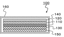
- the lithium ion secondary battery of the present embodiment is, for example, a lithium ion secondary battery schematically showing a cross-sectional view in FIG.
- a lithium ion secondary battery 100 shown in FIG. 1 includes a separator 110, a positive electrode 120 and a negative electrode 130 that sandwich the separator 110 from both sides, and a positive electrode current collector 140 that sandwiches a laminate thereof (arranged outside the positive electrode). And a negative electrode current collector 150 (arranged outside the negative electrode) and a battery outer case 160 for housing them.
- a laminate in which the positive electrode 120, the separator 110, and the negative electrode 130 are laminated is impregnated with the electrolytic solution according to the present embodiment.
- those provided in a conventional lithium ion secondary battery can be used except for the electrolytic solution, and for example, those described above may be used.
- the lithium ion secondary battery of this embodiment is produced by a known method using the above-described electrolytic solution, positive electrode, negative electrode, and, if necessary, a separator.
- a laminate in which a separator is interposed between the electrode and the negative electrode.
- the laminated body is accommodated in a battery case (exterior), the electrolytic solution according to the present embodiment is injected into the case, and the laminated body is immersed in the electrolytic solution and sealed.
- the lithium ion secondary battery can be manufactured.
- an electrolyte membrane containing a gelled electrolyte solution is prepared in advance, and a positive electrode, a negative electrode, an electrolyte membrane, and a separator as necessary are formed by bending or stacking as described above, and then a battery case A lithium ion secondary battery can also be produced by being housed inside.
- the shape of the lithium ion secondary battery of the present embodiment is not particularly limited, and for example, a cylindrical shape, an elliptical shape, a rectangular tube shape, a button shape, a coin shape, a flat shape, and a laminated shape are suitably employed.
- the electrolyte for the lithium ion secondary battery of the present embodiment achieves high conductivity (diffusion of lithium ions and transport number of lithium ions) and high safety (for example, flame retardancy, liquid retention), and lithium ion
- the secondary battery has high battery characteristics (for example, charge / discharge characteristics, low temperature operability, high temperature durability, etc.) and at the same time realizes high safety (lithium dendrite).
- the electrolytic solution contains a gelling agent that has little influence on its properties
- the electrolytic solution for lithium ion secondary batteries and the lithium ion secondary battery of this embodiment are particularly suitable for conventional polymer batteries. It is possible to suppress a significant decrease in the conductivity at low temperatures and battery characteristics.
- the electrolytic solution contains a gelling agent, leakage of the electrolytic solution to the outside of the battery can be prevented, as well as the lithium ion secondary battery of the present embodiment has a risk of lithium dendrite and combustion. The risk can be further reduced.
- the observed peak height is E
- the peak height when the magnetic field gradient pulse is not applied is E 0
- the nuclear magnetic rotation ratio is ⁇ (T ⁇ 1 ⁇ s ⁇ 1 )
- the magnetic field gradient intensity Is g (T ⁇ m ⁇ 1 )
- magnetic field gradient pulse application time is ⁇ (s)
- diffusion waiting time is ⁇ (s)
- self-diffusion coefficient is D (m 2 ⁇ s ⁇ 1 ), 17) holds.
- Ln (E / E 0 ) ⁇ D ⁇ ⁇ 2 ⁇ g 2 ⁇ ⁇ 2 ⁇ ( ⁇ / 3) (17)
- the bpp-led-DOSY method was used as the NMR sequence.
- ⁇ and ⁇ are fixed, and g is changed by 15 points or more in a range from 0 to Ln (E / E 0 ) ⁇ ⁇ 3, and Ln (E / E 0 ) is changed to Y axis, ⁇ 2 ⁇ g 2 ⁇ ⁇ D was obtained from the slope of a straight line plotted with 2 ⁇ ( ⁇ / 3) as the X axis. Measurement was performed using 7 Li (lithium ion) and 19 F (counter anion) as the measurement nucleus. It can be determined that the diffusion rate increases as the diffusion coefficient increases. Further, the lithium ion transport number was calculated from the diffusion coefficient ratio of lithium ions and counter anions.
- Electrolyte safety test (combustion test) The safety of the battery was evaluated by conducting a combustion test of the electrolyte component. 1 mL of the electrolyte solution heated to 70 ° C. was absorbed onto a 13 mm ⁇ 125 mm ⁇ 2 mm glass filter paper, and then the glass filter paper was cooled to 25 ° C. to prepare a sample. The sample was set in “mcm-2” (trade name), a multi-calorie meter manufactured by Toyo Seiki Co., Ltd., and a horizontal combustion test of UL94HB was performed. After ignition, it took time for the flame to propagate to the edge of the filter paper. Time (elapsed time) was measured. It can be judged that the longer the time, the more effective the delay of combustion, and the higher the safety.
- V Measurement of discharge capacity of lithium ion secondary battery
- the discharge capacity of a lithium ion secondary battery was evaluated by measuring the discharge capacity at a specific discharge current.
- (Vi) Measurement of discharge capacity of laminate-type lithium ion secondary battery The discharge capacity was measured in the same manner as "(v) Measurement of discharge capacity of lithium ion secondary battery” to evaluate the discharge characteristics of the lithium ion secondary battery.
- Lithium ion secondary battery capacity retention rate measurement (cycle test) The capacity retention rate was measured using a charge / discharge device ACD-01 (trade name) manufactured by Asuka Electronics Co., Ltd. and a thermostat PLM-63S (trade name) manufactured by Futaba Kagaku.
- a lithium ion secondary battery for measurement a battery produced in the same manner as in “(v) Measurement of discharge capacity of lithium ion secondary battery” was used.
- the charge / discharge cycle test first, the battery was charged at a constant current of 6 mA, reached 4.2 V, and then charged at a constant voltage of 4.2 V for a total of 3 hours.
- the battery was discharged at a constant current of 6 mA, and when it reached 3.0 V, charging was repeated again. Charging and discharging were performed once each as one cycle, and 100 cycles of charging and discharging were performed. The discharge capacity at the 100th cycle when the discharge capacity at the first cycle was taken as 100% was taken as the capacity retention rate.
- the ambient temperature of the battery was set to 25 ° C.
- (X) Lithium Deposition Test of Lithium Ion Secondary Battery A lithium deposition test was performed using a single layer laminate type battery produced in the same manner as “(vi) Measurement of discharge capacity of laminate type lithium ion secondary battery”. The battery charged to 4.2 V at a constant current of 9.0 mA was discharged to 3.0 V at 9.0 mA, and further charged for 1.5 hours at a constant current of 45 mA. The rechargeable battery was disassembled in an atmosphere having a dew point of ⁇ 60 ° C. or lower and a water concentration of 10 ppm or lower. The negative electrode surface of the disassembled battery was observed with an optical microscope having a magnification of 2000 times, and the lithium deposition behavior was evaluated according to the following criteria.
- A No precipitation of lithium is observed.
- B Precipitation of lithium is observed, but the surface of the precipitate is smooth.
- C Precipitation of lithium is observed, and sharp dendrites are observed on the surface of the precipitate. In addition, precipitation of dendrite causes a short circuit of the battery, and causes a decrease in battery safety.
- Example 1 Preparation of electrolyte solution Ethylene carbonate and methyl ethyl carbonate were mixed at a mass ratio of 1: 2, and the mixture was gelled by adding LiPF 6 to 1 mol / L.
- An electrolytic solution (A) was prepared (hereinafter, the electrolytic solution before addition of the gelling agent is referred to as “mother electrolytic solution”).
- mother electrolytic solution To the mother electrolyte (A), a compound represented by the following formula (8) is added as a gelling agent, heated to 70 ° C. and uniformly mixed, and then cooled to 25 ° C. a) was obtained.
- the gelling agent when the gelling agent was gradually added to the mother electrolyte from a small amount, it gelled sufficiently when the addition amount reached 0.3% by mass with respect to the total amount of the electrolyte. The addition of the agent was stopped. That is, the content of the gelling agent with respect to the total amount of the electrolytic solution (a) was 0.3% by mass.
- Example 2 Instead of the mother electrolyte (A), ethylene carbonate, propylene carbonate, and ⁇ -butyrolactone were mixed at a mass ratio of 1: 1: 2, and LiBF 4 was added to the mixture at 1.5 mol / L.
- An electrolytic solution (b) was obtained in the same manner as in Example 1 except that the mother electrolytic solution (B) prepared by adding the same was used.
- Example 9 An electrolytic solution (i) was obtained in the same manner as in Example 2, except that the compound represented by the above formula (14) was used as the gelling agent instead of the compound represented by the above formula (8). .
- the electrolyte solutions of Examples 1 to 11 were evaluated as described in “(i) Evaluation of gelling ability of electrolyte solution” above. The results are shown in Table 1.
- Example 12 to 16 One of the gelling agents represented by the above formulas (8), (9), (11), (14) and (16) is added to the mother electrolyte (A) in the amount shown in Table 2 ( Electrolytic solutions (l), (n), (o), (p) and (q) were prepared in the same manner as in Example 1, except that the total amount of the electrolytic solution was added). The electrolyte solution was subjected to the measurement described in “(ii) Measurement of diffusion coefficient of electrolyte solution component” above. The results are shown in Table 2.
- Example 17 The same procedure as in Example 2, except that the gelling agent represented by the above formula (14) was added to the mother electrolyte (B) in the addition amount shown in Table 2 (based on the total amount of the electrolyte). Thus, an electrolytic solution (r) was prepared. With respect to the electrolytic solution, the measurement described in “(ii) Measurement of diffusion coefficient of electrolytic solution component” was performed only at 30 ° C. The results are shown in Table 3.
- Examples 18 to 23, Comparative Example 4 The electrolyte solution was the same as in Example 1 except that 3.0% by mass of the gelling agent represented by the above formula (8) was added to the mother electrolyte solution (A) based on the total amount of the electrolyte solution. (M) was prepared. Regarding the electrolytic solutions (l), (m), (n), (o), (p) and (q) and the mother electrolytic solution (A), the above “(iii) Safety test of the electrolytic solution (combustion test)” The test described in 1. was performed. The results are shown in Table 4.
- Example 25 ⁇ Preparation of positive electrode> 85: 10: 5 lithium cobaltic acid (LiCoO 2 ) having a number average particle diameter of 5 ⁇ m as a positive electrode active material, graphite carbon powder having a number average particle diameter of 3 ⁇ m as a conductive additive, and polyvinylidene fluoride (PVdF) as a binder. Mixed by mass ratio. N-methyl-2-pyrrolidone was added to the obtained mixture so as to have a solid content of 60% by mass and further mixed to prepare a slurry solution. This slurry-like solution was applied to one side of an aluminum foil having a thickness of 20 ⁇ m, and the solvent was dried and removed, followed by rolling with a roll press. The rolled product was punched into a disk shape having a diameter of 16 mm to obtain a positive electrode ( ⁇ ).
- LiCoO 2 lithium cobaltic acid
- graphite carbon powder having a number average particle diameter of 3 ⁇ m as a conductive additive
- PVdF poly
- ⁇ Battery assembly> A laminate in which the positive electrode ( ⁇ ) and the negative electrode ( ⁇ ) produced as described above are superimposed on both sides of a polyethylene separator (film thickness 25 ⁇ m, porosity 50%, pore diameter 0.1 ⁇ m to 1 ⁇ m), It was inserted into a SUS disk type battery case. Next, 0.5 mL of the electrolytic solution (l) heated to 70 ° C. is injected into the battery case, and the laminate is immersed in the electrolytic solution (l). Then, the battery case is sealed and a lithium ion secondary battery (small size) Battery). The lithium ion secondary battery was held at 70 ° C. for 1 hour, and then cooled to 25 ° C. to obtain a battery (l1).
- Example 26 Comparative Example 6
- Batteries (m1) and (A1) were obtained in the same manner as in Example 25 except that the electrolytic solution (m) or (A) was used instead of the electrolytic solution (l).
- Example 27 Lithium nickel, manganese and cobalt mixed oxide having a number average particle diameter of 11 ⁇ m as a positive electrode active material, graphite carbon powder having a number average particle diameter of 6.5 ⁇ m and acetylene black powder having a number average particle diameter of 48 nm as a conductive auxiliary agent, and a binder And polyvinylidene fluoride (PVdF) were mixed at a mass ratio of 100: 4.2: 1.8: 4.6. N-methyl-2-pyrrolidone was added to the obtained mixture so as to have a solid content of 68% by mass and further mixed to prepare a slurry solution.
- PVdF polyvinylidene fluoride
- This slurry-like solution was applied to one side of an aluminum foil having a thickness of 20 ⁇ m, and the solvent was dried and removed, followed by rolling with a roll press. The rolled product was punched into a disk shape with a diameter of 16 mm to obtain a positive electrode ( ⁇ ).
- the slurry solution was applied to one side of a 10 ⁇ m thick copper foil, and the solvent was removed by drying, followed by rolling with a roll press.
- the rolled product was punched into a disk shape having a diameter of 16 mm to obtain a negative electrode ( ⁇ ).
- ⁇ Battery assembly> A laminate in which the positive electrode ( ⁇ ) and the negative electrode ( ⁇ ) produced as described above are laminated on both sides of a separator made of polyethylene (film thickness 25 ⁇ m, porosity 50%, pore diameter 0.1 ⁇ m to 1 ⁇ m), It was inserted into a SUS disk type battery case. Next, 0.5 mL of the electrolytic solution (l) heated to 70 ° C. is injected into the battery case, and the laminate is immersed in the electrolytic solution (l). Then, the battery case is sealed and a lithium ion secondary battery (small size) Battery). The lithium ion secondary battery was held at 70 ° C. for 1 hour, and then cooled to 25 ° C. to obtain a battery (l2).
- Examples 28 to 31, Comparative Example 7 instead of the electrolytic solution (l), each of the electrolytic solutions (n), (o), (p) and (q) and the mother electrolytic solution (A) was used in the same manner as in Example 27, respectively. Batteries (n), (o), (p), (q) and (A2) were obtained.
- Example 32 ⁇ Preparation of positive electrode> Lithium cobalt acid (LiCoO 2 ) as a positive electrode active material, acetylene black as a conductive additive, and polyvinylidene fluoride (PVdF) as a binder were mixed at a mass ratio of 89.5: 4.5: 6.0. N-methyl-2-pyrrolidone was further mixed with the obtained mixture to prepare a slurry solution. This slurry solution was applied to an aluminum foil having a thickness of 20 ⁇ m and a width of 200 nm, and the solvent was removed by drying, followed by rolling with a roll press and further vacuum drying at 150 ° C. for 10 hours to form a rectangular shape of 50 mm ⁇ 30 mm.
- Lithium cobalt acid (LiCoO 2 ) as a positive electrode active material, acetylene black as a conductive additive, and polyvinylidene fluoride (PVdF) as a binder were mixed at a mass ratio of 8
- a positive electrode ( ⁇ ) was obtained by punching.
- the amount per unit area is 24.8 g / cm 2 ⁇ 3%
- the thickness on one side is 82.6 ⁇ m ⁇ 3%
- the density is 3.0 g ⁇
- the slurry-like solution was prepared while adjusting the amount of the solvent so that cm 3 ⁇ 3% and the coating width was 150 nm with respect to the aluminum foil width of 200 nm.
- Graphite carbon powder (trade name “MCMB25-28”, manufactured by Osaka Gas Chemical Co., Ltd.) as a negative electrode active material, acetylene black as a conductive additive, and polyvinylidene fluoride (PVdF) as a binder, 93.0: 2 Mixed at a mass ratio of 0.0: 5.0.
- N-methyl-2-pyrrolidone was further mixed with the obtained mixture to prepare a slurry solution.
- This slurry solution was applied to a copper foil having a thickness of 14 ⁇ m and a width of 200 nm, and after removing the solvent by drying, it was rolled with a roll press and further vacuum-dried at 150 ° C.
- the amount per unit area is 11.8 g / cm 2 ⁇ 3%
- the thickness on one side is 84.6 ⁇ m ⁇ 3%
- the density is 1.4 g ⁇
- the slurry solution was prepared while adjusting the amount of the solvent so that cm 3 ⁇ 3% and the coating width was 150 nm with respect to the copper foil width of 200 nm.
- ⁇ Battery assembly> Two laminated films (no drawing, thickness 120 ⁇ m, 68 mm ⁇ 48 mm) laminated with an aluminum layer and a resin layer were stacked with the aluminum layer side facing out, and three sides were sealed to produce a laminate cell exterior. . Subsequently, a polyethylene microporous membrane (film thickness 20 ⁇ m, 53 mm ⁇ 33 mm) is prepared as a separator, and a plurality of positive electrodes ( ⁇ ) and negative electrodes ( ⁇ ) produced as described above are alternately stacked via separators. The laminated body was placed in the laminate cell exterior. Next, an electrolytic solution (m) heated to 75 ° C. was injected into the cell exterior, and the laminate was immersed in the electrolytic solution.
- m electrolytic solution
- Example 8 A battery (A3; single-layer laminated battery) was obtained in the same manner as in Example 32 except that the mother electrolyte (A) was used instead of the electrolyte (m).
- the lithium ion secondary battery of the present invention is expected to be used as a rechargeable battery for automobiles such as hybrid cars, plug-in hybrid cars and electric cars in addition to portable devices such as mobile phones, portable audios, and personal computers.
- SYMBOLS 100 Lithium ion secondary battery, 110 ... Separator, 120 ... Positive electrode, 130 ... Negative electrode, 140 ... Positive electrode collector, 150 ... Negative electrode collector, 160 ... Battery exterior.
Abstract
Description
一方、高分子ゲル化剤とは、三次元的なネットワーク構造を分子内に有する高分子化合物群のことである。高分子ゲル化剤として、例えばポリエーテル系化合物などがよく知られている。
高分子ゲル化剤についての研究例は多く、様々な分野に展開されている。 Conventionally, low molecular weight or high molecular weight organic gelling agents have been used to solidify organic liquids in various industrial fields. As a low molecular weight gelling agent, for example, a low molecular weight compound group having a hydrogen bonding functional group such as an amino group, an amide group or a urea group in the molecule is known. Low molecular weight gelling agents are suitably used in fields such as cosmetics, cosmetics, and sludge treatment.
On the other hand, the polymer gelling agent is a group of polymer compounds having a three-dimensional network structure in the molecule. As polymer gelling agents, for example, polyether compounds are well known.
There are many examples of research on polymer gelling agents, which are being developed in various fields.
そこで、本発明は上記事情にかんがみてなされたものであり、高い電池特性を有すると同時に高い安全性をも実現するリチウムイオン二次電池用電解液及びリチウムイオン二次電池を提供することを目的とする。 On the other hand, there are currently few examples of research on batteries using low molecular weight organic gelling agents.
Accordingly, the present invention has been made in view of the above circumstances, and an object thereof is to provide an electrolytic solution for a lithium ion secondary battery and a lithium ion secondary battery that have high battery characteristics and at the same time realize high safety. And
[1]非水溶媒と、リチウム塩と、下記一般式(1)で表される化合物と、を含有するリチウムイオン二次電池用電解液。

[2]前記Ar1は、置換又は無置換の核原子数8~20の2価の芳香族基である、[1]に記載のリチウムイオン二次電池用電解液。
[3]前記Ar1は、ビフェニレン基、ナフチレン基、ターフェニレン基及びアントラニレン基からなる群より選ばれる基である、[1]又は[2]に記載のリチウムイオン二次電池用電解液。
[4]前記非水溶媒は、2種類以上の溶媒の混合溶媒である、[1]~[3]のいずれか一つに記載のリチウムイオン二次電池用電解液。
[5]前記電解液はゲル化したものである、[1]~[4]のいずれか一つに記載のリチウムイオン二次電池用電解液。
[6][1]~[5]のいずれか一つに記載のリチウムイオン二次電池用電解液と、
正極活物質としてリチウムイオンを吸蔵及び放出することが可能な材料からなる群より選ばれる1種以上の材料を含有する正極と、
負極活物質としてリチウムイオンを吸蔵及び放出することが可能な材料及び金属リチウムからなる群より選ばれる1種以上の材料を含有する負極と、
を備えるリチウムイオン二次電池。
[7]前記正極は、前記正極活物質として、リチウム含有化合物を含む、[6]に記載のリチウムイオン二次電池。
[8]前記リチウム含有化合物は、リチウムを有する金属酸化物及びリチウムを有する金属カルコゲン化物からなる群より選ばれる1種以上の化合物を含む、[7]に記載のリチウムイオン二次電池。
[9]前記負極は、前記負極活物質として、金属リチウム、炭素材料、及び、リチウムと合金形成が可能な元素を含む材料、からなる群より選ばれる1種以上の材料を含有する、[6]~[8]のいずれか一つに記載のリチウムイオン二次電池。 That is, the present invention is as follows.
[1] An electrolyte solution for a lithium ion secondary battery containing a nonaqueous solvent, a lithium salt, and a compound represented by the following general formula (1).
[2] The electrolyte for a lithium ion secondary battery according to [1], wherein Ar 1 is a substituted or unsubstituted divalent aromatic group having 8 to 20 nuclear atoms.
[3] The electrolyte for a lithium ion secondary battery according to [1] or [2], wherein Ar 1 is a group selected from the group consisting of a biphenylene group, a naphthylene group, a terphenylene group, and an anthranylene group.
[4] The electrolyte solution for a lithium ion secondary battery according to any one of [1] to [3], wherein the non-aqueous solvent is a mixed solvent of two or more kinds of solvents.
[5] The electrolyte for a lithium ion secondary battery according to any one of [1] to [4], wherein the electrolyte is gelled.
[6] The electrolyte solution for a lithium ion secondary battery according to any one of [1] to [5];
A positive electrode containing at least one material selected from the group consisting of materials capable of inserting and extracting lithium ions as a positive electrode active material;
A negative electrode containing at least one material selected from the group consisting of a material capable of inserting and extracting lithium ions as a negative electrode active material and metallic lithium;
A lithium ion secondary battery comprising:
[7] The lithium ion secondary battery according to [6], wherein the positive electrode includes a lithium-containing compound as the positive electrode active material.
[8] The lithium ion secondary battery according to [7], wherein the lithium-containing compound includes one or more compounds selected from the group consisting of a metal oxide having lithium and a metal chalcogenide having lithium.
[9] The negative electrode contains, as the negative electrode active material, one or more materials selected from the group consisting of metallic lithium, a carbon material, and a material containing an element capable of forming an alloy with lithium, [6] ] The lithium ion secondary battery according to any one of [8] to [8].
本実施形態に係る電解液は、(i)非水溶媒と(ii)リチウム塩と(iii)ゲル化剤とを含有する。
(i)非水溶媒としては、非プロトン性溶媒が挙げられ、非プロトン性極性溶媒が好ましい。その具体例としては、例えば、エチレンカーボネート、プロピレンカーボネート、1,2-ブチレンカーボネート、トランス-2,3-ブチレンカーボネート、シス-2,3-ブチレンカーボネート、1,2-ペンチレンカーボネート、トランス-2,3-ペンチレンカーボネート、シス-2,3-ペンチレンカーボネート、トリフルオロメチルエチレンカーボネート、フルオロエチレンカーボネート、1,2-ジフルオロエチレンカーボネートに代表される環状カーボネート;γ-ブチロラクトン、γ-バレロラクトンに代表されるラクトン;スルホランに代表される環状スルホン;テトラヒドロフラン、ジオキサンに代表される環状エーテル;メチルエチルカーボネート、ジメチルカーボネート、ジエチルカーボネート、メチルプロピルカーボネート、メチルイソプロピルカーボネート、ジプロピルカーボネート、メチルブチルカーボネート、ジブチルカーボネート、エチルプロピルカーボネート、メチルトリフルオロエチルカーボネートに代表される鎖状カーボネート;アセトニトリルに代表されるニトリル;ジメチルエーテルに代表されるエーテル;プロピオン酸メチルに代表される鎖状カルボン酸エステル;ジメトキシエタンに代表される鎖状エーテルカーボネート化合物が挙げられる。これらは1種を単独で又は2種以上を組み合わせて用いられる。 <Electrolyte>
The electrolytic solution according to this embodiment contains (i) a nonaqueous solvent, (ii) a lithium salt, and (iii) a gelling agent.
(I) The non-aqueous solvent includes an aprotic solvent, and an aprotic polar solvent is preferable. Specific examples thereof include, for example, ethylene carbonate, propylene carbonate, 1,2-butylene carbonate, trans-2,3-butylene carbonate, cis-2,3-butylene carbonate, 1,2-pentylene carbonate, trans-2. , 3-pentylene carbonate, cis-2,3-pentylene carbonate, trifluoromethylethylene carbonate, fluoroethylene carbonate, cyclic carbonates typified by 1,2-difluoroethylene carbonate; γ-butyrolactone, γ-valerolactone Typical lactones; Cyclic sulfones represented by sulfolane; Cyclic ethers represented by tetrahydrofuran and dioxane; Methyl ethyl carbonate, Dimethyl carbonate, Diethyl carbonate, Methyl propyl carbonate -Bonate, methyl isopropyl carbonate, dipropyl carbonate, methyl butyl carbonate, dibutyl carbonate, ethyl propyl carbonate, chain carbonate represented by methyl trifluoroethyl carbonate; nitrile represented by acetonitrile; ether represented by dimethyl ether; propionic acid Examples thereof include a chain carboxylic acid ester typified by methyl; a chain ether carbonate compound typified by dimethoxyethane. These are used singly or in combination of two or more.
LiC(SO2R11)(SO2R12)(SO2R13) (5a)
LiN(SO2OR14)(SO2OR15) (5b)
LiN(SO2R16)(SO2OR17) (5c)
ここで、式中、R11、R12、R13、R14、R15、R16及びR17は、互いに同一であっても異なっていてもよく、炭素数1~8のパーフルオロアルキル基を示す。 Further, lithium salts represented by the following general formulas (5a), (5b) and (5c) can also be used.
LiC (SO 2 R 11 ) (SO 2 R 12 ) (SO 2 R 13 ) (5a)
LiN (SO 2 OR 14 ) (SO 2 OR 15 ) (5b)
LiN (SO 2 R 16 ) (SO 2 OR 17 ) (5c)
Here, in the formula, R 11 , R 12 , R 13 , R 14 , R 15 , R 16 and R 17 may be the same as or different from each other, and are a perfluoroalkyl group having 1 to 8 carbon atoms. Indicates.
リチウム塩は、電解液中に好ましくは0.1~3モル/リットル、より好ましくは0.5~2モル/リットルの濃度で含有される。 These lithium salts are used singly or in combination of two or more. Of these lithium salts, LiPF 6 , LiBF 4 and LiN (SO 2 C k F 2k + 1 ) 2 [k is an integer of 1 to 8] are particularly preferable.
The lithium salt is preferably contained in the electrolytic solution at a concentration of 0.1 to 3 mol / liter, more preferably 0.5 to 2 mol / liter.
複素環式の基は、その核原子数が5~30であり、例えば、ピローレン基、フラニレン基、チオフェニレン基、トリアゾーレン基、オキサジアゾーレン基、ピリジレン基及びピリミジレン基に代表される核を有する2価の基が挙げられる。
Ar1は、原料入手容易性及び合成容易性の観点並びに電解液に対するゲル化能の観点から、置換又は無置換の核原子数8~20の2価の芳香族基であると好ましく、ビフェニレン基、ナフチレン基、ターフェニレン基及びアントラニレン基からなる群より選ばれる基であるとより好ましい。
また、上記置換基としては、メチル基及びエチル基に代表されるアルキル基、並びにハロゲン原子が挙げられる。 The carbocyclic group has 6 to 30 nuclear atoms, may be substituted with a substituent, or may be unsubstituted or unsubstituted. Specific examples thereof include divalent groups having a nucleus represented by a phenylene group, a biphenylene group, a terphenylene group, a naphthylene group, an anthranylene group, a phenanthrylene group, a pyrenylene group, a chrysenylene group, and a fluoranthenylene group. It is done.
The heterocyclic group has 5 to 30 nuclear atoms, and includes, for example, nuclei represented by a pyrrolene group, a furylene group, a thiophenylene group, a triazolen group, an oxadiazolene group, a pyridylene group, and a pyrimidylene group. And a divalent group.
Ar 1 is preferably a substituted or unsubstituted divalent aromatic group having 8 to 20 nucleus atoms from the viewpoints of availability of raw materials and ease of synthesis and gelling ability with respect to the electrolyte, and is preferably a biphenylene group. And a group selected from the group consisting of a naphthylene group, a terphenylene group and an anthranylene group.
Moreover, as said substituent, the alkyl group represented by the methyl group and the ethyl group, and a halogen atom are mentioned.
下記一般式(1a)で表される芳香族化合物をテトラヒドロフラン(THF)等の溶媒に溶解し、アミン等の塩基の存在下でペルフルオロアルキル(オリゴメチレン)基を有する下記一般式(1b)で表されるハロゲン化化合物と反応させる。その後、塩酸で中和し、溶媒及び未反応物質を留去して、水酸基及びペルフルオロアルキル(オリゴメチレン)基を有する下記一般式(1c)で表される芳香族化合物を生成する。なお、それぞれの式中、Ar1、m及びpは、それぞれ一般式(1)におけるものと同義であり、X1はチオール基との反応性を有するハロゲン原子を示し、例えば、塩素原子、臭素原子、ヨウ素原子及びフッ素原子が挙げられる。

An aromatic compound represented by the following general formula (1a) is dissolved in a solvent such as tetrahydrofuran (THF) and is represented by the following general formula (1b) having a perfluoroalkyl (oligomethylene) group in the presence of a base such as an amine. Reaction with the halogenated compound. Then, it neutralizes with hydrochloric acid, and a solvent and an unreacted substance are distilled off, The aromatic compound represented by the following general formula (1c) which has a hydroxyl group and a perfluoroalkyl (oligomethylene) group is produced | generated. In each formula, Ar 1 , m and p have the same meanings as in general formula (1), and X 1 represents a halogen atom having reactivity with a thiol group. For example, chlorine atom, bromine An atom, an iodine atom, and a fluorine atom are mentioned.
上記一般式(1c)で表される芳香族化合物を溶媒に溶解した溶液に、ハロゲン化炭化水素と塩基とを加え還流して反応させる。反応終了後、必要に応じて一旦濾過し、反応液から溶媒及び未反応物質を留去し、残渣をシリカゲルクロマトグラフにより精製する。こうして、炭化水素オキシ基を導入して、化合物(1’)を得る。上記ハロゲン化炭化水素におけるハロゲン原子としては、上記一般式(1c)で表される芳香族化合物の水酸基OHとの反応性を有していればよく、塩素原子、臭素原子、ヨウ素原子及びフッ素原子が挙げられる。 [Introduction of hydrocarbon oxy groups]
A halogenated hydrocarbon and a base are added to a solution obtained by dissolving the aromatic compound represented by the general formula (1c) in a solvent, and the mixture is refluxed for reaction. After completion of the reaction, if necessary, it is filtered once, the solvent and unreacted substances are distilled off from the reaction solution, and the residue is purified by silica gel chromatography. Thus, the hydrocarbon oxy group is introduced to obtain the compound (1 ′). The halogen atom in the halogenated hydrocarbon is only required to have reactivity with the hydroxyl group OH of the aromatic compound represented by the general formula (1c), and includes a chlorine atom, a bromine atom, an iodine atom, and a fluorine atom. Is mentioned.
化合物(1’)を溶媒に溶解した溶液に、過酸化水素水などの酸化剤を加えて加熱しながら撹拌して酸化反応させる。反応終了後、エーテル及び水を用いて抽出分離をし、水相を除去した後、さらに有機相から溶媒及び未反応物質を留去し、残渣をシリカゲルクロマトグラフにより精製する。こうして、スルフィド基をスルホニル基へ酸化して化合物(1)を得る。 [Oxidation of sulfide group to sulfonyl group]
An oxidant such as aqueous hydrogen peroxide is added to a solution obtained by dissolving the compound (1 ′) in a solvent, and the mixture is stirred while heating to cause an oxidation reaction. After completion of the reaction, extraction and separation are performed using ether and water, and the aqueous phase is removed. Then, the solvent and unreacted substances are further distilled off from the organic phase, and the residue is purified by silica gel chromatography. In this way, the sulfide group is oxidized to a sulfonyl group to obtain the compound (1).
リチウム塩としては、目的に応じて様々な塩が選択できるが、LiPF6、LiBF4及びLiN(SO2CkF2k+1)2〔kは1~8の整数〕が好ましい。このリチウム塩は、電池特性や安定性に加え、ゲル化能を高めることができる。 As the non-aqueous solvent, an aprotic polar solvent is preferably used, and among them, it is preferable to include at least one cyclic aprotic polar solvent. It is preferable that the non-aqueous solvent contains, for example, a cyclic carbonate represented by ethylene carbonate and propylene carbonate as a cyclic aprotic polar solvent. The cyclic compound has a high dielectric constant, and is effective in helping ionization of the lithium salt and enhancing the gelation ability.
As the lithium salt, various salts can be selected depending on the purpose, but LiPF 6 , LiBF 4 and LiN (SO 2 C k F 2k + 1 ) 2 [k is an integer of 1 to 8] are preferable. This lithium salt can increase the gelation ability in addition to battery characteristics and stability.
正極は、リチウムイオン二次電池の正極として作用するものであれば特に限定されず、公知のものであってもよい。正極は、正極活物質としてリチウムイオンを吸蔵及び放出することが可能な材料からなる群より選ばれる1種以上の材料を含有すると好ましい。そのような材料としては、例えば、下記一般式(6a)及び(6b)で表される複合酸化物、トンネル構造及び層状構造の金属カルコゲン化物及び金属酸化物が挙げられる。
LixMO2 (6a)
LiyM2O4 (6b)
ここで、式中、Mは遷移金属から選ばれる1種以上の金属を示し、xは0~1の数、yは0~2の数を示す。 <Positive electrode>
A positive electrode will not be specifically limited if it acts as a positive electrode of a lithium ion secondary battery, A well-known thing may be used. The positive electrode preferably contains one or more materials selected from the group consisting of materials capable of inserting and extracting lithium ions as the positive electrode active material. Examples of such materials include composite oxides represented by the following general formulas (6a) and (6b), metal chalcogenides and metal oxides having a tunnel structure and a layered structure.
Li x MO 2 (6a)
Li y M 2 O 4 (6b)
Here, in the formula, M represents one or more metals selected from transition metals, x represents a number from 0 to 1, and y represents a number from 0 to 2.
LivMIO2 (7a)
LiwMIIPO4 (7b)
ここで、式中、MI及びMIIはそれぞれ1種以上の遷移金属元素を示し、v及びwの値は電池の充放電状態によって異なるが、通常vは0.05~1.10、wは0.05~1.10の数を示す。 More specifically, the lithium-containing compound is preferably a metal oxide having lithium, a metal chalcogenide having lithium, and a metal phosphate compound having lithium. For example, the lithium-containing compounds are represented by the following general formulas (7a) and (7b), respectively. The compound which is made is mentioned.
Li v M I O 2 (7a )
Li w M II PO 4 (7b)
Here, in the formula, M I and M II each represent one or more transition metal elements, and the values of v and w vary depending on the charge / discharge state of the battery, but usually v is 0.05 to 1.10, w Represents a number from 0.05 to 1.10.
ここで、正極合剤含有ペースト中の固形分濃度は、好ましくは30~80質量%であり、より好ましくは40~70質量%である。
正極集電体は、例えば、アルミニウム箔、又はステンレス箔などの金属箔により構成される。 The positive electrode is obtained, for example, as follows. That is, first, a positive electrode mixture-containing paste is prepared by dispersing, in a solvent, a positive electrode mixture obtained by adding a conductive additive, a binder, or the like to the positive electrode active material as necessary. Next, this positive electrode mixture-containing paste is applied to a positive electrode current collector and dried to form a positive electrode mixture layer, which is pressurized as necessary to adjust the thickness, thereby producing a positive electrode.
Here, the solid content concentration in the positive electrode mixture-containing paste is preferably 30 to 80% by mass, and more preferably 40 to 70% by mass.
The positive electrode current collector is made of, for example, a metal foil such as an aluminum foil or a stainless steel foil.
負極は、リチウムイオン二次電池の負極として作用するものであれば特に限定されず、公知のものであってもよい。負極は、負極活物質としてリチウムイオンを吸蔵及び放出することが可能な材料及び金属リチウムからなる群より選ばれる1種以上の材料を含有すると好ましい。そのような材料としては金属リチウムの他、例えば、アモルファスカーボン(ハードカーボン)、人造黒鉛、天然黒鉛、黒鉛、熱分解炭素、コークス、ガラス状炭素、有機高分子化合物の焼成体、メソカーボンマイクロビーズ、炭素繊維、活性炭、グラファイト、炭素コロイド、カーボンブラックに代表される炭素材料が挙げられる。これらのうち、コークスとしては、例えば、ピッチコークス、ニードルコークス及び石油コークスが挙げられる。また、有機高分子化合物の焼成体は、フェノール樹脂やフラン樹脂などの高分子材料を適当な温度で焼成して炭素化したものである。なお、本発明においては、負極活物質に金属リチウムを採用した電池もリチウムイオン二次電池に含めるものとする。 <Negative electrode>
A negative electrode will not be specifically limited if it acts as a negative electrode of a lithium ion secondary battery, A well-known thing may be used. The negative electrode preferably contains at least one material selected from the group consisting of a material capable of inserting and extracting lithium ions as a negative electrode active material and metallic lithium. Examples of such materials include lithium metal, amorphous carbon (hard carbon), artificial graphite, natural graphite, graphite, pyrolytic carbon, coke, glassy carbon, organic polymer compound fired body, mesocarbon microbeads. Carbon materials represented by carbon fiber, activated carbon, graphite, carbon colloid, and carbon black. Among these, examples of the coke include pitch coke, needle coke, and petroleum coke. Further, the fired body of the organic polymer compound is obtained by firing and polymerizing a polymer material such as a phenol resin or a furan resin at an appropriate temperature. In the present invention, a battery employing metallic lithium as the negative electrode active material is also included in the lithium ion secondary battery.
ここで、負極合剤含有ペースト中の固形分濃度は、好ましくは30~80質量%であり、より好ましくは40~70質量%である。
負極集電体は、例えば、銅箔、ニッケル箔又はステンレス箔などの金属箔により構成される。 A negative electrode is obtained as follows, for example. That is, first, a negative electrode mixture-containing paste is prepared by dispersing, in a solvent, a negative electrode mixture prepared by adding a conductive additive or a binder to the negative electrode active material, if necessary. Next, the negative electrode mixture-containing paste is applied to a negative electrode current collector and dried to form a negative electrode mixture layer, which is pressurized as necessary to adjust the thickness, thereby producing a negative electrode.
Here, the solid content concentration in the negative electrode mixture-containing paste is preferably 30 to 80% by mass, more preferably 40 to 70% by mass.
The negative electrode current collector is made of, for example, a metal foil such as a copper foil, a nickel foil, or a stainless steel foil.
本実施形態のリチウムイオン二次電池は、正負極の短絡防止、シャットダウン等の安全性付与の観点から、正極と負極との間にセパレータを備えると好ましい。セパレータとしては、公知のリチウムイオン二次電池に備えられるものと同様であってもよく、イオン透過性が大きく、機械的強度に優れる絶縁性の薄膜が好ましい。セパレータとしては、例えば、織布、不織布、合成樹脂製微多孔膜が挙げられ、これらの中でも、合成樹脂製微多孔膜が好ましい。合成樹脂製微多孔膜としては、例えば、ポリエチレン又はポリプロピレンを主成分として含有する微多孔膜、あるいは、これらのポリオレフィンを共に含有する微多孔膜等のポリオレフィン系微多孔膜が好適に用いられる。不織布としては、セラミック製、ポリオレフィン製、ポリエステル製、ポリアミド製、液晶ポリエステル製、アラミド製など、耐熱樹脂製の多孔膜が用いられる。
セパレータは、1種の微多孔膜を単層又は複数積層したものであってもよく、2種以上の微多孔膜を積層したものであってもよい。 <Separator>
The lithium ion secondary battery of the present embodiment preferably includes a separator between the positive electrode and the negative electrode from the viewpoint of providing safety such as prevention of short circuit between the positive and negative electrodes and shutdown. The separator may be the same as that provided for a known lithium ion secondary battery, and is preferably an insulating thin film having high ion permeability and excellent mechanical strength. Examples of the separator include a woven fabric, a nonwoven fabric, and a synthetic resin microporous membrane. Among these, a synthetic resin microporous membrane is preferable. As the synthetic resin microporous membrane, for example, a microporous membrane containing polyethylene or polypropylene as a main component or a polyolefin microporous membrane such as a microporous membrane containing both of these polyolefins is preferably used. As the nonwoven fabric, a porous film made of a heat-resistant resin such as ceramic, polyolefin, polyester, polyamide, liquid crystal polyester, or aramid is used.
The separator may be a single microporous membrane or a laminate of a plurality of microporous membranes, or may be a laminate of two or more microporous membranes.
本実施形態のリチウムイオン二次電池は、上述の電解液、正極、負極及び必要に応じてセパレータを用いて、公知の方法により作製される。例えば、正極と負極とを、その間にセパレータを介在させた積層状態で巻回して巻回構造の積層体に成形したり、それらを折り曲げや複数層の積層などによって、交互に積層した複数の正極と負極との間にセパレータが介在する積層体に成形したりする。次いで、電池ケース(外装)内にその積層体を収容して、本実施形態に係る電解液をケース内部に注液し、上記積層体を電解液に浸漬して封印することによって、本実施形態のリチウムイオン二次電池を作製することができる。あるいは、ゲル化させた電解液を含む電解質膜を予め作製しておき、正極、負極、電解質膜及び必要に応じてセパレータを、上述のように折り曲げや積層によって積層体を形成した後、電池ケース内に収容してリチウムイオン二次電池を作製することもできる。本実施形態のリチウムイオン二次電池の形状は、特に限定されず、例えば、円筒形、楕円形、角筒型、ボタン形、コイン形、扁平形及びラミネート形などが好適に採用される。 <Production method of battery>
The lithium ion secondary battery of this embodiment is produced by a known method using the above-described electrolytic solution, positive electrode, negative electrode, and, if necessary, a separator. For example, a plurality of positive electrodes in which a positive electrode and a negative electrode are wound in a laminated state with a separator interposed therebetween to be formed into a laminate having a wound structure, or they are alternately laminated by bending or laminating a plurality of layers. Or a laminate in which a separator is interposed between the electrode and the negative electrode. Next, the laminated body is accommodated in a battery case (exterior), the electrolytic solution according to the present embodiment is injected into the case, and the laminated body is immersed in the electrolytic solution and sealed. The lithium ion secondary battery can be manufactured. Alternatively, an electrolyte membrane containing a gelled electrolyte solution is prepared in advance, and a positive electrode, a negative electrode, an electrolyte membrane, and a separator as necessary are formed by bending or stacking as described above, and then a battery case A lithium ion secondary battery can also be produced by being housed inside. The shape of the lithium ion secondary battery of the present embodiment is not particularly limited, and for example, a cylindrical shape, an elliptical shape, a rectangular tube shape, a button shape, a coin shape, a flat shape, and a laminated shape are suitably employed.
電解液をガラスサンプル瓶内で調製し、25℃で2時間放置した後にサンプル瓶を上下逆にして、その際の流動性を確認することでゲル化能を評価した。流動しないものを「ゲル」と評価し、非水溶媒とゲル化剤との混合比を変化させ、電解液をゲル化させるために必要なゲル化剤の最低濃度(電解液の総量を基準とするゲル化剤の濃度)をゲル化濃度として求めた。 (I) Evaluation of gelling ability of electrolyte solution After preparing an electrolyte solution in a glass sample bottle and leaving it to stand at 25 ° C for 2 hours, the sample bottle is turned upside down to check the fluidity at that time. Noh was evaluated. Those that do not flow are evaluated as “gels”, the mixing ratio of the non-aqueous solvent and the gelling agent is changed, and the minimum concentration of gelling agent required to gel the electrolyte (based on the total amount of electrolyte) The concentration of the gelling agent) was determined as the gelation concentration.
調製した電解液をシゲミ社製対称型試料管(5mmΦ、DMSO用)に導入し、所定温度(-20℃、30℃、70℃)でのリチウムイオン及び対アニオンの拡散係数を評価した。拡散係数の評価は、日本電子社製のPFG-NMRであるECA400(商品名、周波数400MHz)を用い、13T/mまで磁場勾配パルス印加が可能なGRプローブを装着して行った。磁場勾配NMR測定法では、観測されるピーク高さをE、磁場勾配パルスを与えない場合のピーク高さをE0、核磁気回転比をγ(T-1・s-1)、磁場勾配強度をg(T・m-1)、磁場勾配パルス印加時間をδ(s)、拡散待ち時間をΔ(s)、自己拡散係数をD(m2・s-1)とした場合、下記式(17)が成り立つ。 Ln(E/E0)=-D×γ2×g2×δ2×(Δ-δ/3) (17)
NMRシーケンスとしてbpp-led-DOSY法を用いた。Δ及びδを固定して、gを0からLn(E/E0)≦-3となる範囲で15点以上変化させ、Ln(E/E0)をY軸、γ2×g2×δ2×(Δ-δ/3)をX軸としてプロットした直線の傾きからDを得た。測定核には7Li(リチウムイオン)、19F(対アニオン)を用いて測定した。拡散係数が大きいほど拡散速度が大きいと判断できる。
また、リチウムイオン及び対アニオンの拡散係数比からリチウムイオン輸率を算出した。 (Ii) Measurement of diffusion coefficient of electrolyte component
The prepared electrolyte was introduced into a symmetrical sample tube (5 mmΦ, for DMSO) manufactured by Shigemi Co., Ltd., and the diffusion coefficients of lithium ions and counter anions at predetermined temperatures (−20 ° C., 30 ° C., 70 ° C.) were evaluated. Evaluation of the diffusion coefficient was performed using ECA400 (trade name, frequency 400 MHz), which is PFG-NMR manufactured by JEOL Ltd., with a GR probe capable of applying a magnetic field gradient pulse up to 13 T / m. In the magnetic field gradient NMR measurement method, the observed peak height is E, the peak height when the magnetic field gradient pulse is not applied is E 0 , the nuclear magnetic rotation ratio is γ (T −1 · s −1 ), and the magnetic field gradient intensity. Is g (T · m −1 ), magnetic field gradient pulse application time is δ (s), diffusion waiting time is Δ (s), and self-diffusion coefficient is D (m 2 · s −1 ), 17) holds. Ln (E / E 0 ) = − D × γ 2 × g 2 × δ 2 × (Δ−δ / 3) (17)
The bpp-led-DOSY method was used as the NMR sequence. Δ and δ are fixed, and g is changed by 15 points or more in a range from 0 to Ln (E / E 0 ) ≦ −3, and Ln (E / E 0 ) is changed to Y axis, γ 2 × g 2 × δ D was obtained from the slope of a straight line plotted with 2 × (Δ−δ / 3) as the X axis. Measurement was performed using 7 Li (lithium ion) and 19 F (counter anion) as the measurement nucleus. It can be determined that the diffusion rate increases as the diffusion coefficient increases.
Further, the lithium ion transport number was calculated from the diffusion coefficient ratio of lithium ions and counter anions.
電解液成分の燃焼試験を行い電池の安全性を評価した。70℃に昇温した電解液を13mm×125mm×2mmのガラスろ紙に1mL吸液させた後、そのガラスろ紙を25℃まで降温することでサンプルを調製した。サンプルを東洋精機(株)製のマルチカロリーメーターである「mcm―2」(商品名)にセットし、UL94HBの水平燃焼試験を行い、着火後、炎がろ紙の端まで伝播するのに要した時間(経過時間)を測定した。時間が長いほど燃焼を遅延させる効果があり、安全性が高いと判断できる。 (Iii) Electrolyte safety test (combustion test)
The safety of the battery was evaluated by conducting a combustion test of the electrolyte component. 1 mL of the electrolyte solution heated to 70 ° C. was absorbed onto a 13 mm × 125 mm × 2 mm glass filter paper, and then the glass filter paper was cooled to 25 ° C. to prepare a sample. The sample was set in “mcm-2” (trade name), a multi-calorie meter manufactured by Toyo Seiki Co., Ltd., and a horizontal combustion test of UL94HB was performed. After ignition, it took time for the flame to propagate to the edge of the filter paper. Time (elapsed time) was measured. It can be judged that the longer the time, the more effective the delay of combustion, and the higher the safety.
電解液成分を5cm2×0.012cmのポリプロピレン製不織布(空隙率73%)に十分に含浸させた後、その不織布を2枚のガラス板で挟むことでサンプルを調製した。当該サンプルを台に載置し、片面(上面)からサンプルを油圧プレスで加圧して、漏液が開始した時の圧力を測定した。また、加圧前後のサンプルの質量を測定し、4kgf/cm2(約0.39MPa)まで加圧したときの保液率、すなわち含浸した電解液の質量に対する加圧前後でのサンプルの質量差を求めた。 (Iv) Liquid retention test of electrolyte solution After sufficiently impregnating a 5 cm 2 × 0.012 cm polypropylene non-woven fabric (porosity 73%) with an electrolyte component, the non-woven fabric is sandwiched between two glass plates. Samples were prepared. The sample was placed on a table, the sample was pressurized from one side (upper surface) with a hydraulic press, and the pressure at the start of liquid leakage was measured. Further, the mass of the sample before and after pressurization was measured, and the liquid retention rate when pressurized to 4 kgf / cm 2 (about 0.39 MPa), that is, the mass difference of the sample before and after pressurization with respect to the mass of the impregnated electrolyte Asked.
特定の放電電流における放電容量を測定してリチウムイオン二次電池の放電特性を評価した。測定用のリチウムイオン二次電池として、1C=6mAとなる小型電池を作製して用いた。測定は、アスカ電子(株)製充放電装置ACD-01(商品名)及び二葉科学社製恒温槽PLM-63S(商品名)を用いて行った。6mAの定電流で充電し、4.2Vに到達した後、4.2Vの定電圧で、合計3時間充電を行った。その後、定電流で3.0Vまで放電したときの放電容量を測定した。なお、放電電流を6mAと18mAとにして放電容量を測定した。このときの電池周囲温度は25℃に設定した。 (V) Measurement of discharge capacity of lithium ion secondary battery The discharge capacity of a lithium ion secondary battery was evaluated by measuring the discharge capacity at a specific discharge current. As a lithium ion secondary battery for measurement, a small battery with 1C = 6 mA was prepared and used. The measurement was performed using a charge / discharge device ACD-01 (trade name) manufactured by Asuka Electronics Co., Ltd. and a thermostatic chamber PLM-63S (trade name) manufactured by Futaba Kagaku. After charging at a constant current of 6 mA and reaching 4.2 V, charging was performed at a constant voltage of 4.2 V for a total of 3 hours. Then, the discharge capacity when discharging to 3.0 V with a constant current was measured. The discharge capacity was measured by setting the discharge current to 6 mA and 18 mA. The battery ambient temperature at this time was set to 25 ° C.
「(v)リチウムイオン二次電池の放電容量測定」と同様に放電容量を測定してリチウムイオン二次電池の放電特性を評価した。測定用のリチウムイオン二次電池として、1C=45.0mAとなる単層ラミネート型電池を作製して用いた。測定は、アスカ電子(株)製充放電装置ACD-01(商品名)及び二葉科学社製恒温槽PLM-63S(商品名)を用いて行った。9.0mAの定電流で充電し、4.2Vに到達した後、4.2Vの定電圧で、合計8時間充電を行った。その後、定電流で2.75Vまで放電したときの放電容量を測定した。なお、放電電流を45.0mAと135.0mAとにして放電容量を測定した。このときの電池周囲温度は25℃に設定した。 (Vi) Measurement of discharge capacity of laminate-type lithium ion secondary battery The discharge capacity was measured in the same manner as "(v) Measurement of discharge capacity of lithium ion secondary battery" to evaluate the discharge characteristics of the lithium ion secondary battery. As a lithium ion secondary battery for measurement, a single-layer laminated battery with 1C = 45.0 mA was prepared and used. The measurement was performed using a charge / discharge device ACD-01 (trade name) manufactured by Asuka Electronics Co., Ltd. and a thermostatic chamber PLM-63S (trade name) manufactured by Futaba Kagaku. After charging at a constant current of 9.0 mA and reaching 4.2 V, charging was performed at a constant voltage of 4.2 V for a total of 8 hours. Then, the discharge capacity when discharging to 2.75 V with a constant current was measured. The discharge capacity was measured at discharge currents of 45.0 mA and 135.0 mA. The battery ambient temperature at this time was set to 25 ° C.
容量維持率の測定は、アスカ電子(株)製充放電装置ACD-01(商品名)及び二葉科学社製恒温槽PLM-63S(商品名)を用いて行った。測定用のリチウムイオン二次電池として、「(v)リチウムイオン二次電池の放電容量測定」と同様にして作製した電池を用いた。充放電サイクル試験では、まず、6mAの定電流で充電し、4.2Vに到達した後、4.2Vの定電圧で、合計3時間充電を行った。その後、6mAの定電流で放電し、3.0Vに到達した時点で再び、充電を繰り返した。充電と放電とを各々1回ずつ行うのを1サイクルとし、100サイクルの充放電を行った。1サイクル目の放電容量を100%としたときの100サイクル目の放電容量を容量維持率とした。電池の周囲温度は25℃に設定した。 (Vii) Lithium ion secondary battery capacity retention rate measurement (cycle test)
The capacity retention rate was measured using a charge / discharge device ACD-01 (trade name) manufactured by Asuka Electronics Co., Ltd. and a thermostat PLM-63S (trade name) manufactured by Futaba Kagaku. As a lithium ion secondary battery for measurement, a battery produced in the same manner as in “(v) Measurement of discharge capacity of lithium ion secondary battery” was used. In the charge / discharge cycle test, first, the battery was charged at a constant current of 6 mA, reached 4.2 V, and then charged at a constant voltage of 4.2 V for a total of 3 hours. Thereafter, the battery was discharged at a constant current of 6 mA, and when it reached 3.0 V, charging was repeated again. Charging and discharging were performed once each as one cycle, and 100 cycles of charging and discharging were performed. The discharge capacity at the 100th cycle when the discharge capacity at the first cycle was taken as 100% was taken as the capacity retention rate. The ambient temperature of the battery was set to 25 ° C.
電池周囲温度を-20℃、-10℃、0℃にそれぞれ設定して、「(v)リチウムイオン二次電池の放電容量測定」と同様にして放電容量を測定した。なお、放電電流を3mAにして放電容量を測定した。 (Viii) Measurement of discharge capacity of lithium ion secondary battery at low temperature The battery ambient temperature was set to −20 ° C., −10 ° C. and 0 ° C., respectively, and “(v) measurement of discharge capacity of lithium ion secondary battery” Similarly, the discharge capacity was measured. The discharge capacity was measured with a discharge current of 3 mA.
電池周囲温度を60℃に設定して、「(vii)リチウムイオン二次電池の容量維持率測定(サイクル試験)」と同様にして充放電サイクル試験を50サイクルまで行い、高温時の容量維持率を測定した。 (Ix) High-temperature endurance test of lithium ion secondary battery Charge / discharge cycle in the same manner as “(vii) Lithium ion secondary battery capacity maintenance rate measurement (cycle test)” with battery ambient temperature set to 60 ° C. The test was conducted up to 50 cycles, and the capacity retention rate at high temperature was measured.
リチウム析出試験は、「(vi)ラミネート型リチウムイオン二次電池の放電容量測定」と同様にして作製した単層ラミネート型電池を用いて行った。9.0mAの定電流で4.2Vまで充電した電池を9.0mAで3.0Vまで放電し、さらに45mAの定電流で1.5時間充電を行った。この充電池を露点が-60℃以下、水分濃度10ppm以下の雰囲気下で解体した。解体した電池の負極表面を倍率2000倍の光学顕微鏡で観察し、リチウム析出挙動を下記の基準で評価した。
A:リチウムの析出が認められない。
B:リチウムの析出は認められるが析出物の表面は平滑である。
C:リチウムの析出が認められ、析出物の表面には鋭い樹状突起(デンドライト)が認められる。
なお、デンドライトの析出は電池短絡の要因となり、電池の安全性が低下する原因となる。 (X) Lithium Deposition Test of Lithium Ion Secondary Battery A lithium deposition test was performed using a single layer laminate type battery produced in the same manner as “(vi) Measurement of discharge capacity of laminate type lithium ion secondary battery”. The battery charged to 4.2 V at a constant current of 9.0 mA was discharged to 3.0 V at 9.0 mA, and further charged for 1.5 hours at a constant current of 45 mA. The rechargeable battery was disassembled in an atmosphere having a dew point of −60 ° C. or lower and a water concentration of 10 ppm or lower. The negative electrode surface of the disassembled battery was observed with an optical microscope having a magnification of 2000 times, and the lithium deposition behavior was evaluated according to the following criteria.
A: No precipitation of lithium is observed.
B: Precipitation of lithium is observed, but the surface of the precipitate is smooth.
C: Precipitation of lithium is observed, and sharp dendrites are observed on the surface of the precipitate.
In addition, precipitation of dendrite causes a short circuit of the battery, and causes a decrease in battery safety.
(1)電解液の調製
エチレンカーボネートとメチルエチルカーボネートとを質量比で1:2になるように混合し、その混合液に、LiPF6を1モル/Lになるよう添加してゲル化されていない電解液(A)を作製した(以下、ゲル化剤添加前の電解液を「母電解液」という。)。その母電解液(A)に対して、ゲル化剤として下記式(8)で表される化合物を添加し、70℃に加熱して均一に混合した後、25℃に降温して電解液(a)を得た。なお、ゲル化剤を少量から徐々に母電解液に添加していったところ、添加量が電解液の総量に対して0.3質量%に達したときに十分にゲル化したので、そこでゲル化剤の添加を停止した。すなわち、電解液(a)の総量に対するゲル化剤の含有量は0.3質量%であった。 Example 1
(1) Preparation of electrolyte solution Ethylene carbonate and methyl ethyl carbonate were mixed at a mass ratio of 1: 2, and the mixture was gelled by adding LiPF 6 to 1 mol / L. An electrolytic solution (A) was prepared (hereinafter, the electrolytic solution before addition of the gelling agent is referred to as “mother electrolytic solution”). To the mother electrolyte (A), a compound represented by the following formula (8) is added as a gelling agent, heated to 70 ° C. and uniformly mixed, and then cooled to 25 ° C. a) was obtained. In addition, when the gelling agent was gradually added to the mother electrolyte from a small amount, it gelled sufficiently when the addition amount reached 0.3% by mass with respect to the total amount of the electrolyte. The addition of the agent was stopped. That is, the content of the gelling agent with respect to the total amount of the electrolytic solution (a) was 0.3% by mass.
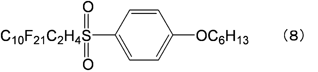
母電解液(A)に代えて、エチレンカーボネートとプロピレンカーボネートとγ-ブチロラクトンとを質量比で1:1:2になるように混合し、その混合液にLiBF4を1.5モル/Lになるよう添加して作製した母電解液(B)を用いる以外は実施例1と同様にして、電解液(b)を得た。 (Example 2)
Instead of the mother electrolyte (A), ethylene carbonate, propylene carbonate, and γ-butyrolactone were mixed at a mass ratio of 1: 1: 2, and LiBF 4 was added to the mixture at 1.5 mol / L. An electrolytic solution (b) was obtained in the same manner as in Example 1 except that the mother electrolytic solution (B) prepared by adding the same was used.
ゲル化剤として、上記式(8)で表される化合物に代えて、下記式(9)、(10)、(11)、(12)、(13)、(14)、(15)及び(16)で表される化合物のいずれかを用いた以外は実施例1と同様にして、電解液(c)、(d)、(e)、(f)、(g)、(h)、(j)及び(k)をそれぞれ得た。 (Examples 3 to 8, 10, 11)
As a gelling agent, instead of the compound represented by the above formula (8), the following formulas (9), (10), (11), (12), (13), (14), (15) and (15) 16) Except that any one of the compounds represented by 16) was used, the electrolytic solutions (c), (d), (e), (f), (g), (h), (h) j) and (k) were obtained respectively.
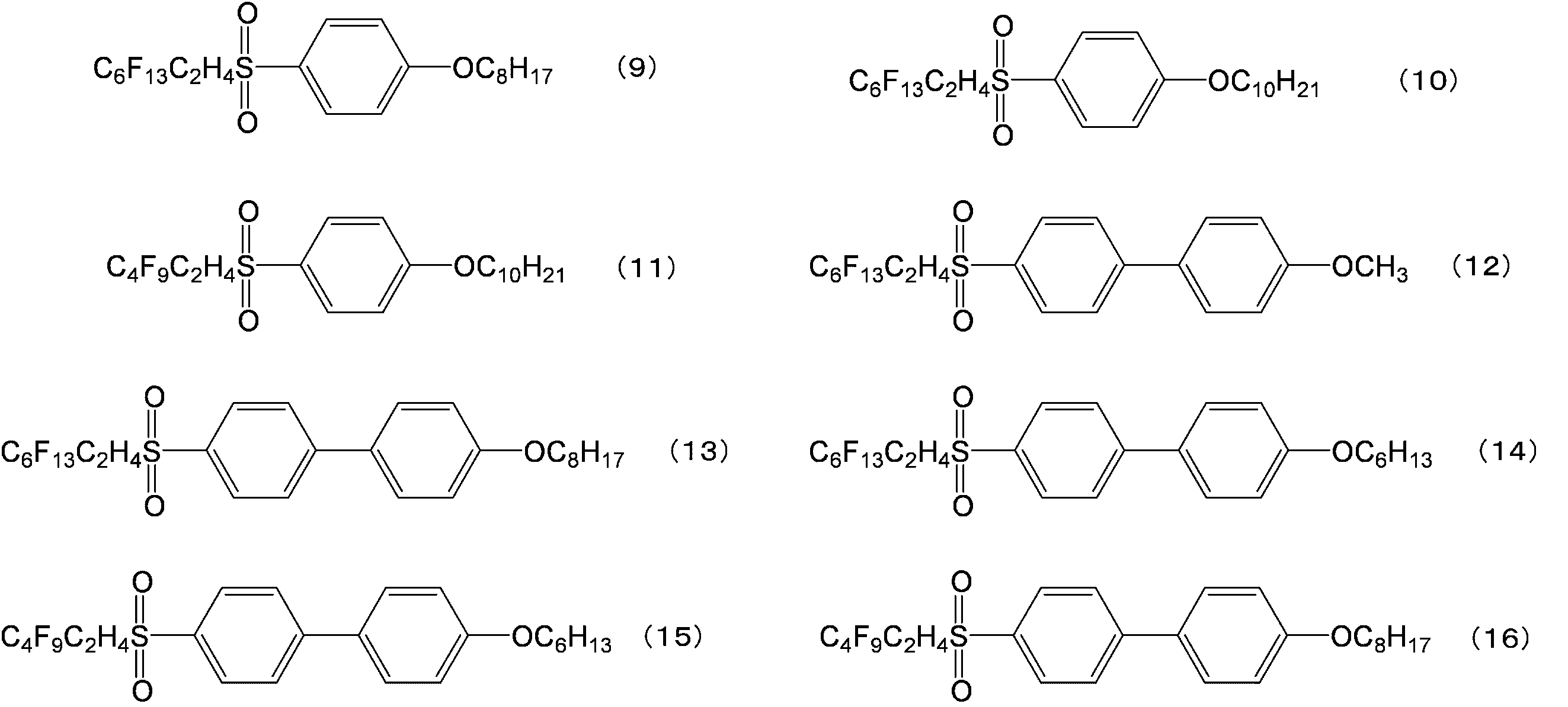
ゲル化剤として、上記式(8)で表される化合物に代えて、上記式(14)で表される化合物を用いた以外は実施例2と同様にして、電解液(i)を得た。
実施例1~11の電解液について、上記「(i)電解液のゲル化能の評価」に記載の評価を行った。結果を表1に示す。 Example 9
An electrolytic solution (i) was obtained in the same manner as in Example 2, except that the compound represented by the above formula (14) was used as the gelling agent instead of the compound represented by the above formula (8). .
The electrolyte solutions of Examples 1 to 11 were evaluated as described in “(i) Evaluation of gelling ability of electrolyte solution” above. The results are shown in Table 1.
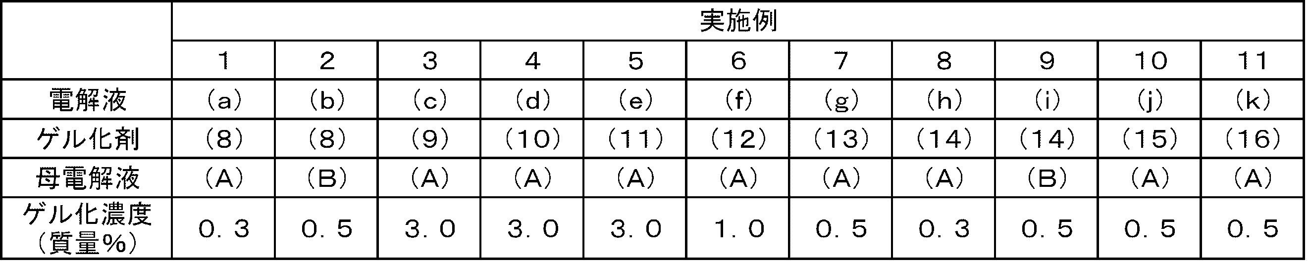
母電解液(A)に対して、上記式(8)、(9)、(11)、(14)及び(16)で表されるゲル化剤のいずれかを、表2に示す添加量(電解液の総量を基準として)で添加した以外は実施例1と同様にして、電解液(l)、(n)、(o)、(p)及び(q)をそれぞれ調製した。その電解液について、上記「(ii)電解液成分の拡散係数測定」に記載の測定を行った。結果を表2に示す。 (Examples 12 to 16)
One of the gelling agents represented by the above formulas (8), (9), (11), (14) and (16) is added to the mother electrolyte (A) in the amount shown in Table 2 ( Electrolytic solutions (l), (n), (o), (p) and (q) were prepared in the same manner as in Example 1, except that the total amount of the electrolytic solution was added). The electrolyte solution was subjected to the measurement described in “(ii) Measurement of diffusion coefficient of electrolyte solution component” above. The results are shown in Table 2.

母電解液(A)をそのまま電解液として用いた。その電解液について、上記「(ii)電解液成分の拡散係数測定」に記載の測定を行った。結果を表2に示す。 (Comparative Example 1)
The mother electrolyte (A) was used as the electrolyte as it was. The electrolyte solution was subjected to the measurement described in “(ii) Measurement of diffusion coefficient of electrolyte solution component” above. The results are shown in Table 2.
母電解液(B)に対して、上記式(14)で表されるゲル化剤を、表2に示す添加量(電解液の総量を基準として)で添加した以外は実施例2と同様にして、電解液(r)を調製した。その電解液について、上記「(ii)電解液成分の拡散係数測定」に記載の測定を、30℃のみで行った。結果を表3に示す。 (Example 17)
The same procedure as in Example 2, except that the gelling agent represented by the above formula (14) was added to the mother electrolyte (B) in the addition amount shown in Table 2 (based on the total amount of the electrolyte). Thus, an electrolytic solution (r) was prepared. With respect to the electrolytic solution, the measurement described in “(ii) Measurement of diffusion coefficient of electrolytic solution component” was performed only at 30 ° C. The results are shown in Table 3.
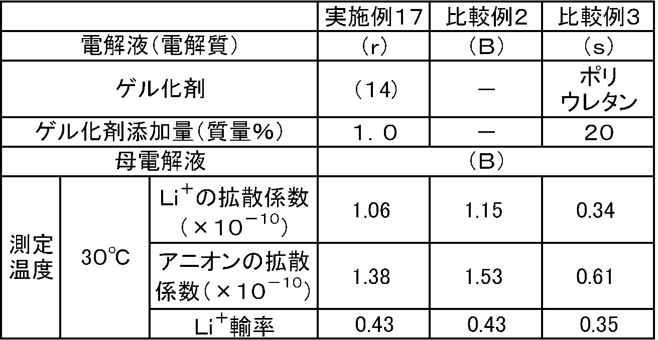
母電解液(B)をそのまま電解液として用いた。その電解液をついて、上記「(ii)電解液成分の拡散係数測定」に記載の測定を、30℃のみで行った。結果を表3に示す。 (Comparative Example 2)
The mother electrolyte (B) was used as the electrolyte as it was. With respect to the electrolytic solution, the measurement described in “(ii) Measurement of diffusion coefficient of electrolytic solution component” was performed only at 30 ° C. The results are shown in Table 3.
母電解液(B)に対して、数平均分子量(GPC法により測定)が1000、OH価が110mgKOH/gのジオール化合物とイソシアネートとから合成されたポリウレタンを(電解液の総量を基準として)20質量%添加し、そのポリウレタンに母電解液(B)を吸液させてポリウレタンゲル電解質(s)を得た。電解質(s)の電解液成分について、上記「(ii)電解液成分の拡散係数測定」に記載の測定を、30℃のみで行った。結果を表3に示す。 (Comparative Example 3)
Polyurethane synthesized from a diol compound having a number average molecular weight (measured by GPC method) of 1000 and an OH value of 110 mgKOH / g and an isocyanate (based on the total amount of the electrolyte) with respect to the mother electrolyte (B) 20 A polyurethane gel electrolyte (s) was obtained by adding mass% and allowing the polyurethane to absorb the mother electrolyte (B). For the electrolyte component of the electrolyte (s), the measurement described in the above “(ii) Measurement of diffusion coefficient of electrolyte component” was performed only at 30 ° C. The results are shown in Table 3.
母電解液(A)に対して、上記式(8)で表されるゲル化剤を、電解液の総量を基準として3.0質量%添加した以外は実施例1と同様にして、電解液(m)を調製した。電解液(l)、(m)、(n)、(o)、(p)及び(q)並びに母電解液(A)について、上記「(iii)電解液の安全性試験(燃焼試験)」に記載の試験を行った。結果を表4に示す。 (Examples 18 to 23, Comparative Example 4)
The electrolyte solution was the same as in Example 1 except that 3.0% by mass of the gelling agent represented by the above formula (8) was added to the mother electrolyte solution (A) based on the total amount of the electrolyte solution. (M) was prepared. Regarding the electrolytic solutions (l), (m), (n), (o), (p) and (q) and the mother electrolytic solution (A), the above “(iii) Safety test of the electrolytic solution (combustion test)” The test described in 1. was performed. The results are shown in Table 4.
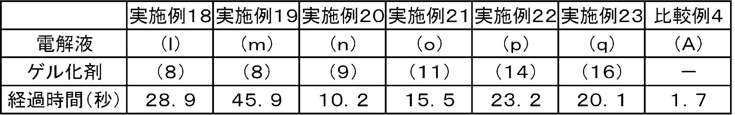
電解液(m)及び母電解液(A)について、上記「(iv)電解液の保液性試験」に記載の試験を行った。結果を表5に示す。 (Example 24, Comparative Example 5)
The electrolyte solution (m) and the mother electrolyte solution (A) were subjected to the test described in “(iv) Liquid retention test of electrolyte solution”. The results are shown in Table 5.
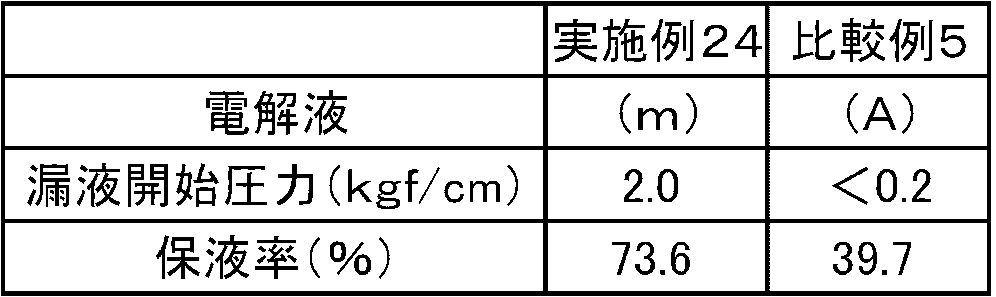
<正極の作製>
正極活物質として数平均粒子径5μmのリチウムコバルト酸(LiCoO2)と、導電助剤として数平均粒子径3μmのグラファイト炭素粉末と、バインダーとしてポリフッ化ビニリデン(PVdF)とを85:10:5の質量比で混合した。得られた混合物にN-メチル-2-ピロリドンを固形分60質量%となるように投入して更に混合して、スラリー状の溶液を調製した。このスラリー状の溶液を厚さ20μmのアルミニウム箔の片面に塗布し、溶剤を乾燥除去した後、ロールプレスで圧延した。圧延後のものを直径16mmの円盤状に打ち抜いて正極(α)を得た。 (Example 25)
<Preparation of positive electrode>
85: 10: 5 lithium cobaltic acid (LiCoO 2 ) having a number average particle diameter of 5 μm as a positive electrode active material, graphite carbon powder having a number average particle diameter of 3 μm as a conductive additive, and polyvinylidene fluoride (PVdF) as a binder. Mixed by mass ratio. N-methyl-2-pyrrolidone was added to the obtained mixture so as to have a solid content of 60% by mass and further mixed to prepare a slurry solution. This slurry-like solution was applied to one side of an aluminum foil having a thickness of 20 μm, and the solvent was dried and removed, followed by rolling with a roll press. The rolled product was punched into a disk shape having a diameter of 16 mm to obtain a positive electrode (α).
負極活物質として数平均粒子径5μmのメソカーボンマイクロビーズと、バインダーとしてジエン系ゴム(ガラス転移温度:-5℃、乾燥時の数平均粒子径:120nm、分散媒:水、固形分濃度40質量%)とをカルボキシメチルセルロースで粘度調整しつつ負極活物質の固形分濃度が60質量%になるように混合して、スラリー状の溶液を調製した。このスラリー状の溶液を厚さ10μmの銅箔の片面に塗布し、溶剤を乾燥除去した後、ロールプレスで圧延した。圧延後のものを直径16mmの円盤状に打ち抜いて負極(β)を得た。 <Production of negative electrode>
Mesocarbon microbeads having a number average particle size of 5 μm as a negative electrode active material and diene rubber as a binder (glass transition temperature: −5 ° C., number average particle size upon drying: 120 nm, dispersion medium: water, solid content concentration of 40 mass) %) Was adjusted so that the solid content concentration of the negative electrode active material was 60% by mass while adjusting the viscosity with carboxymethylcellulose to prepare a slurry-like solution. The slurry solution was applied to one side of a 10 μm thick copper foil, and the solvent was removed by drying, followed by rolling with a roll press. The rolled product was punched into a disk shape with a diameter of 16 mm to obtain a negative electrode (β).
上述のようにして作製した正極(α)と負極(β)とをポリエチレンからなるセパレータ(膜厚25μm、空孔率50%、孔径0.1μm~1μm)の両側に重ね合わせた積層体を、SUS製の円盤型電池ケースに挿入した。次いで、その電池ケース内に70℃に加熱した電解液(l)を0.5mL注入し、積層体を電解液(l)に浸漬した後、電池ケースを密閉してリチウムイオン二次電池(小型電池)を作製した。このリチウムイオン二次電池を70℃で1時間保持した後、25℃まで降温して電池(l1)を得た。 <Battery assembly>
A laminate in which the positive electrode (α) and the negative electrode (β) produced as described above are superimposed on both sides of a polyethylene separator (film thickness 25 μm, porosity 50%, pore diameter 0.1 μm to 1 μm), It was inserted into a SUS disk type battery case. Next, 0.5 mL of the electrolytic solution (l) heated to 70 ° C. is injected into the battery case, and the laminate is immersed in the electrolytic solution (l). Then, the battery case is sealed and a lithium ion secondary battery (small size) Battery). The lithium ion secondary battery was held at 70 ° C. for 1 hour, and then cooled to 25 ° C. to obtain a battery (l1).
電解液(l)に代えて、電解液(m)又は(A)を用いた以外は実施例25と同様にして、それぞれ電池(m1)及び(A1)を得た。 (Example 26, Comparative Example 6)
Batteries (m1) and (A1) were obtained in the same manner as in Example 25 except that the electrolytic solution (m) or (A) was used instead of the electrolytic solution (l).
<正極の作製>
正極活物質として数平均粒子径11μmのリチウムのニッケル、マンガン及びコバルト混合酸化物と、導電助剤として数平均粒子径6.5μmのグラファイト炭素粉末及び数平均粒子径48nmのアセチレンブラック粉末と、バインダーとしてポリフッ化ビニリデン(PVdF)とを、100:4.2:1.8:4.6の質量比で混合した。得られた混合物にN-メチル-2-ピロリドンを固形分68質量%となるように投入して更に混合して、スラリー状の溶液を調製した。このスラリー状の溶液を厚さ20μmのアルミニウム箔の片面に塗布し、溶剤を乾燥除去した後、ロールプレスで圧延した。圧延後のものを直径16mmの円盤状に打ち抜いて正極(γ)を得た。 (Example 27)
<Preparation of positive electrode>
Lithium nickel, manganese and cobalt mixed oxide having a number average particle diameter of 11 μm as a positive electrode active material, graphite carbon powder having a number average particle diameter of 6.5 μm and acetylene black powder having a number average particle diameter of 48 nm as a conductive auxiliary agent, and a binder And polyvinylidene fluoride (PVdF) were mixed at a mass ratio of 100: 4.2: 1.8: 4.6. N-methyl-2-pyrrolidone was added to the obtained mixture so as to have a solid content of 68% by mass and further mixed to prepare a slurry solution. This slurry-like solution was applied to one side of an aluminum foil having a thickness of 20 μm, and the solvent was dried and removed, followed by rolling with a roll press. The rolled product was punched into a disk shape with a diameter of 16 mm to obtain a positive electrode (γ).
負極活物質として数平均粒子径12.7μmのグラファイト炭素粉末及び数平均粒子径6.5μmのグラファイト炭素粉末と、バインダーとしてカルボキシメチルセルロース溶液(固形分濃度1.83質量%)と、ジエン系ゴム(ガラス転移温度:-5℃、乾燥時の数平均粒子径:120nm、分散媒:水、固形分濃度40質量%)とを、90:10:1.44:1.76の固形分質量比で全体の固形分濃度が45質量%になるように混合して、スラリー状の溶液を調製した。このスラリー状の溶液を厚さ10μmの銅箔の片面に塗布し、溶剤を乾燥除去した後、ロールプレスで圧延した。圧延後のものを直径16mmの円盤状に打ち抜いて負極(δ)を得た。 <Production of negative electrode>
Graphite carbon powder having a number average particle diameter of 12.7 μm and graphite carbon powder having a number average particle diameter of 6.5 μm as a negative electrode active material, a carboxymethylcellulose solution (solid content concentration 1.83% by mass) as a binder, and a diene rubber ( Glass transition temperature: −5 ° C., number average particle size upon drying: 120 nm, dispersion medium: water, solid content concentration of 40% by mass) at a solid content mass ratio of 90: 10: 1.44: 1.76 A slurry-like solution was prepared by mixing so that the total solid concentration was 45% by mass. The slurry solution was applied to one side of a 10 μm thick copper foil, and the solvent was removed by drying, followed by rolling with a roll press. The rolled product was punched into a disk shape having a diameter of 16 mm to obtain a negative electrode (δ).
上述のようにして作製した正極(γ)と負極(δ)とをポリエチレンからなるセパレータ(膜厚25μm、空孔率50%、孔径0.1μm~1μm)の両側に重ね合わせた積層体を、SUS製の円盤型電池ケースに挿入した。次いで、その電池ケース内に70℃に加熱した電解液(l)を0.5mL注入し、積層体を電解液(l)に浸漬した後、電池ケースを密閉してリチウムイオン二次電池(小型電池)を作製した。このリチウムイオン二次電池を70℃で1時間保持した後、25℃まで降温して電池(l2)を得た。 <Battery assembly>
A laminate in which the positive electrode (γ) and the negative electrode (δ) produced as described above are laminated on both sides of a separator made of polyethylene (film thickness 25 μm, porosity 50%, pore diameter 0.1 μm to 1 μm), It was inserted into a SUS disk type battery case. Next, 0.5 mL of the electrolytic solution (l) heated to 70 ° C. is injected into the battery case, and the laminate is immersed in the electrolytic solution (l). Then, the battery case is sealed and a lithium ion secondary battery (small size) Battery). The lithium ion secondary battery was held at 70 ° C. for 1 hour, and then cooled to 25 ° C. to obtain a battery (l2).
電解液(l)に代えて、電解液(n)、(o)、(p)及び(q)並びに母電解液(A)のいずれかを用いた以外は実施例27と同様にして、それぞれ電池(n)、(o)、(p)、(q)及び(A2)を得た。 (Examples 28 to 31, Comparative Example 7)
Instead of the electrolytic solution (l), each of the electrolytic solutions (n), (o), (p) and (q) and the mother electrolytic solution (A) was used in the same manner as in Example 27, respectively. Batteries (n), (o), (p), (q) and (A2) were obtained.


<正極の作製>
正極活物質としてリチウムコバルト酸(LiCoO2)と、導電助剤としてアセチレンブラックと、バインダーとしてポリフッ化ビニリデン(PVdF)とを、89.5:4.5:6.0の質量比で混合した。得られた混合物にN-メチル-2-ピロリドンを更に混合して、スラリー状の溶液を調製した。このスラリー状の溶液を厚さ20μm、幅200nmのアルミニウム箔に塗布し、溶剤を乾燥除去した後、ロールプレスで圧延し、更に150℃で10時間真空乾燥を行い、50mm×30mmの矩形状に打ち抜いて正極(ε)を得た。なお、得られた電極における真空乾燥後の合材について、片面あたりの目付量が24.8g/cm2±3%、片面での厚さが82.6μm±3%、密度が3.0g・cm3±3%、塗工幅がアルミニウム箔の幅200nmに対して150nmになるように溶剤量を調整しながら、上記スラリー状の溶液を調製した。 (Example 32)
<Preparation of positive electrode>
Lithium cobalt acid (LiCoO 2 ) as a positive electrode active material, acetylene black as a conductive additive, and polyvinylidene fluoride (PVdF) as a binder were mixed at a mass ratio of 89.5: 4.5: 6.0. N-methyl-2-pyrrolidone was further mixed with the obtained mixture to prepare a slurry solution. This slurry solution was applied to an aluminum foil having a thickness of 20 μm and a width of 200 nm, and the solvent was removed by drying, followed by rolling with a roll press and further vacuum drying at 150 ° C. for 10 hours to form a rectangular shape of 50 mm × 30 mm. A positive electrode (ε) was obtained by punching. In addition, about the compound material after the vacuum drying in the obtained electrode, the amount per unit area is 24.8 g / cm 2 ± 3%, the thickness on one side is 82.6 μm ± 3%, and the density is 3.0 g · The slurry-like solution was prepared while adjusting the amount of the solvent so that cm 3 ± 3% and the coating width was 150 nm with respect to the aluminum foil width of 200 nm.
負極活物質としてグラファイト炭素粉末(商品名「MCMB25-28」、大阪ガスケミカル(株)製)と、導電助剤としてアセチレンブラックと、バインダーとしてポリフッ化ビニリデン(PVdF)とを、93.0:2.0:5.0の質量比で混合した。得られた混合物にN-メチル-2-ピロリドンを更に混合して、スラリー状の溶液を調製した。このスラリー状の溶液を厚さ14μm,幅200nmの銅箔に塗布し、溶剤を乾燥除去した後、ロールプレスで圧延し、更に150℃で10時間真空乾燥を行い、52mm×32mmに打ち抜いて負極(ζ)を得た。なお、得られた電極における真空乾燥後の合材について、片面あたりの目付量が11.8g/cm2±3%、片面での厚さが84.6μm±3%、密度が1.4g・cm3±3%、塗工幅が銅箔の幅200nmに対して150nmになるように溶剤量を調整しながら、上記スラリー状の溶液を調製した。 <Production of negative electrode>
Graphite carbon powder (trade name “MCMB25-28”, manufactured by Osaka Gas Chemical Co., Ltd.) as a negative electrode active material, acetylene black as a conductive additive, and polyvinylidene fluoride (PVdF) as a binder, 93.0: 2 Mixed at a mass ratio of 0.0: 5.0. N-methyl-2-pyrrolidone was further mixed with the obtained mixture to prepare a slurry solution. This slurry solution was applied to a copper foil having a thickness of 14 μm and a width of 200 nm, and after removing the solvent by drying, it was rolled with a roll press and further vacuum-dried at 150 ° C. for 10 hours, and punched out to 52 mm × 32 mm. (Ζ) was obtained. In addition, about the compound material after the vacuum drying in the obtained electrode, the amount per unit area is 11.8 g / cm 2 ± 3%, the thickness on one side is 84.6 μm ± 3%, and the density is 1.4 g · The slurry solution was prepared while adjusting the amount of the solvent so that cm 3 ± 3% and the coating width was 150 nm with respect to the copper foil width of 200 nm.
アルミニウム層と樹脂層とを積層したラミネートフィルム(絞り加工なし、厚さ120μm、68mm×48mm)2枚を、アルミニウム層側を外側にして重ねて、三辺をシールしてラミネートセル外装を作製した。続いて、セパレータとしてポリエチレン製微多孔膜(膜厚20μm、53mm×33mm)を用意し、上述のようにして作製した正極(ε)と負極(ζ)とをセパレータを介して交互に複数重ね合わせた積層体を、ラミネートセル外装内に配置した。次いで、そのセル外装内に75℃に加熱した電解液(m)を注入し、積層体を電解液に浸漬した。なお、電解液(m)の注入は、大気圧と100mmHgの減圧とを気泡発生がなくなるまで繰り返しながら行った。100mmHgに減圧した環境下でラミネートセル外装の残りの一辺をシールしてリチウムイオン二次電池を得た。得られた電池を75℃で2.5時間保持した後、25℃まで降温して電池(m2)を得た。 <Battery assembly>
Two laminated films (no drawing,
電解液(m)に代えて、母電解液(A)を用いた以外は実施例32と同様にして、電池(A3;単層ラミネート型電池)を得た。 (Comparative Example 8)
A battery (A3; single-layer laminated battery) was obtained in the same manner as in Example 32 except that the mother electrolyte (A) was used instead of the electrolyte (m).

DESCRIPTION OF
Claims (9)
- 非水溶媒と、リチウム塩と、下記一般式(1)で表される化合物と、を含有するリチウムイオン二次電池用電解液。

- 前記Ar1は、置換又は無置換の核原子数8~20の2価の芳香族基である、請求項1に記載のリチウムイオン二次電池用電解液。 The electrolyte for a lithium ion secondary battery according to claim 1, wherein Ar 1 is a substituted or unsubstituted divalent aromatic group having 8 to 20 nuclear atoms.
- 前記Ar1は、ビフェニレン基、ナフチレン基、ターフェニレン基及びアントラニレン基からなる群より選ばれる基である、請求項1又は2に記載のリチウムイオン二次電池用電解液。 3. The electrolyte solution for a lithium ion secondary battery according to claim 1, wherein Ar 1 is a group selected from the group consisting of a biphenylene group, a naphthylene group, a terphenylene group, and an anthranylene group.
- 前記非水溶媒は、2種類以上の溶媒の混合溶媒である、請求項1~3のいずれか一項に記載のリチウムイオン二次電池用電解液。 The electrolyte solution for a lithium ion secondary battery according to any one of claims 1 to 3, wherein the non-aqueous solvent is a mixed solvent of two or more kinds of solvents.
- 前記電解液はゲル化したものである、請求項1~4のいずれか一項に記載のリチウムイオン二次電池用電解液。 The electrolyte for a lithium ion secondary battery according to any one of claims 1 to 4, wherein the electrolyte is gelled.
- 請求項1~5のいずれか一項に記載のリチウムイオン二次電池用電解液と、
正極活物質としてリチウムイオンを吸蔵及び放出することが可能な材料からなる群より選ばれる1種以上の材料を含有する正極と、
負極活物質としてリチウムイオンを吸蔵及び放出することが可能な材料及び金属リチウムからなる群より選ばれる1種以上の材料を含有する負極と、
を備えるリチウムイオン二次電池。 An electrolyte for a lithium ion secondary battery according to any one of claims 1 to 5,
A positive electrode containing at least one material selected from the group consisting of materials capable of inserting and extracting lithium ions as a positive electrode active material;
A negative electrode containing at least one material selected from the group consisting of a material capable of inserting and extracting lithium ions as a negative electrode active material and metallic lithium;
A lithium ion secondary battery comprising: - 前記正極は、前記正極活物質として、リチウム含有化合物を含む、請求項6に記載のリチウムイオン二次電池。 The lithium ion secondary battery according to claim 6, wherein the positive electrode includes a lithium-containing compound as the positive electrode active material.
- 前記リチウム含有化合物は、リチウムを有する金属酸化物及びリチウムを有する金属カルコゲン化物からなる群より選ばれる1種以上の化合物を含む、請求項7に記載のリチウムイオン二次電池。 The lithium ion secondary battery according to claim 7, wherein the lithium-containing compound includes one or more compounds selected from the group consisting of a metal oxide having lithium and a metal chalcogenide having lithium.
- 前記負極は、前記負極活物質として、金属リチウム、炭素材料、及び、リチウムと合金形成が可能な元素を含む材料、からなる群より選ばれる1種以上の材料を含有する、請求項6~8のいずれか一項に記載のリチウムイオン二次電池。 The negative electrode contains, as the negative electrode active material, one or more materials selected from the group consisting of metallic lithium, a carbon material, and a material containing an element capable of forming an alloy with lithium. The lithium ion secondary battery as described in any one of these.
Priority Applications (5)
| Application Number | Priority Date | Filing Date | Title |
|---|---|---|---|
| KR1020117019085A KR101274298B1 (en) | 2009-02-18 | 2010-02-12 | Electrolytic solution for lithium-ion secondary battery, and lithium-ion secondary battery |
| EP10743699.0A EP2400588B1 (en) | 2009-02-18 | 2010-02-12 | Electrolyte solution for lithium-ion secondary battery, and lithium-ion secondary battery comprising the same |
| JP2011500586A JP5457429B2 (en) | 2009-02-18 | 2010-02-12 | Electrolyte for lithium ion secondary battery and lithium ion secondary battery |
| CN201080008283.4A CN102326286B (en) | 2009-02-18 | 2010-02-12 | Electrolytic solution for lithium-ion secondary battery, and lithium-ion secondary battery |
| US13/205,096 US8399136B2 (en) | 2009-02-18 | 2011-08-08 | Electrolyte solution for lithium ion secondary battery, lithium ion secondary battery, fluoroalkane derivative and gelling agent |
Applications Claiming Priority (2)
| Application Number | Priority Date | Filing Date | Title |
|---|---|---|---|
| JP2009-035302 | 2009-02-18 | ||
| JP2009035302 | 2009-02-18 |
Related Child Applications (1)
| Application Number | Title | Priority Date | Filing Date |
|---|---|---|---|
| US13/205,096 Continuation-In-Part US8399136B2 (en) | 2009-02-18 | 2011-08-08 | Electrolyte solution for lithium ion secondary battery, lithium ion secondary battery, fluoroalkane derivative and gelling agent |
Publications (1)
| Publication Number | Publication Date |
|---|---|
| WO2010095572A1 true WO2010095572A1 (en) | 2010-08-26 |
Family
ID=42633855
Family Applications (1)
| Application Number | Title | Priority Date | Filing Date |
|---|---|---|---|
| PCT/JP2010/052090 WO2010095572A1 (en) | 2009-02-18 | 2010-02-12 | Electrolytic solution for lithium-ion secondary battery, and lithium-ion secondary battery |
Country Status (7)
| Country | Link |
|---|---|
| US (1) | US8399136B2 (en) |
| EP (1) | EP2400588B1 (en) |
| JP (2) | JP5457429B2 (en) |
| KR (1) | KR101274298B1 (en) |
| CN (1) | CN102326286B (en) |
| TW (1) | TWI416777B (en) |
| WO (1) | WO2010095572A1 (en) |
Cited By (5)
| Publication number | Priority date | Publication date | Assignee | Title |
|---|---|---|---|---|
| WO2011099572A1 (en) * | 2010-02-12 | 2011-08-18 | 旭化成イーマテリアルズ株式会社 | Fluoroalkane derivative, gelling agent and gel composition |
| US8399136B2 (en) | 2009-02-18 | 2013-03-19 | Asahi Kasei E-Materials Corporation | Electrolyte solution for lithium ion secondary battery, lithium ion secondary battery, fluoroalkane derivative and gelling agent |
| JP2013069682A (en) * | 2011-09-05 | 2013-04-18 | Asahi Kasei Corp | Method for manufacturing electrochemical device |
| JP2013171679A (en) * | 2012-02-20 | 2013-09-02 | Asahi Kasei Corp | Nonaqueous battery separator and nonaqueous battery including the same |
| US9118088B2 (en) | 2009-06-10 | 2015-08-25 | Asahi Kasei E-Materials Corporation | Electrolyte solution and lithium ion secondary battery using the same |
Families Citing this family (16)
| Publication number | Priority date | Publication date | Assignee | Title |
|---|---|---|---|---|
| JP5645154B2 (en) * | 2009-06-02 | 2014-12-24 | 旭化成イーマテリアルズ株式会社 | Lithium ion secondary battery |
| US8993177B2 (en) | 2009-12-04 | 2015-03-31 | Envia Systems, Inc. | Lithium ion battery with high voltage electrolytes and additives |
| JP2013171681A (en) * | 2012-02-20 | 2013-09-02 | Asahi Kasei Corp | Nonaqueous battery electrolyte and battery including the same |
| JP2014024778A (en) * | 2012-07-25 | 2014-02-06 | Asahi Kasei Corp | Method for producing aromatic boron compound |
| JP6218413B2 (en) | 2013-03-29 | 2017-10-25 | 株式会社Subaru | Pre-doping agent, power storage device using the same, and manufacturing method thereof |
| US10411299B2 (en) | 2013-08-02 | 2019-09-10 | Zenlabs Energy, Inc. | Electrolytes for stable cycling of high capacity lithium based batteries |
| KR102395989B1 (en) * | 2014-09-17 | 2022-05-10 | 삼성전자주식회사 | Composite electrode, electrochemical cell comprising composite electrode and electrode preparation method |
| JP6430190B2 (en) * | 2014-09-22 | 2018-11-28 | 国立大学法人山口大学 | Electrolyte and lithium ion secondary battery |
| EP3211707B1 (en) * | 2014-10-21 | 2019-12-04 | Nec Corporation | Secondary battery and production method therefor |
| JP6583809B2 (en) * | 2015-03-20 | 2019-10-02 | 国立大学法人山口大学 | Non-aqueous electrolyte and lithium ion secondary battery |
| CN110352525B (en) * | 2017-02-27 | 2023-08-18 | 日本电气株式会社 | Secondary battery and method for manufacturing same |
| KR102248864B1 (en) * | 2017-04-06 | 2021-05-06 | 주식회사 엘지화학 | Anode for secondary battery and method for manufacturing the same |
| CN111261931A (en) * | 2018-12-01 | 2020-06-09 | 深圳格林德能源集团有限公司 | Method for rapidly determining electrolyte amount of high-compaction nickel cobalt manganese oxide lithium battery |
| CN110867611B (en) * | 2019-10-15 | 2023-03-24 | 湖南法恩莱特新能源科技有限公司 | Power lithium ion battery electrolyte of high-nickel ternary cathode material system |
| CN114361587B (en) * | 2021-09-18 | 2024-02-09 | 华中科技大学 | Local high-concentration electrolyte additive for lithium metal secondary battery and application |
| CN115332633B (en) * | 2022-10-13 | 2023-03-24 | 宁德新能源科技有限公司 | Electrochemical device and electronic device |
Citations (3)
| Publication number | Priority date | Publication date | Assignee | Title |
|---|---|---|---|---|
| JP2003323814A (en) * | 2002-04-26 | 2003-11-14 | Sumitomo Bakelite Co Ltd | Lithium ion conducting gel electrolyte |
| JP2007191626A (en) * | 2006-01-20 | 2007-08-02 | Yamaguchi Univ | Gellant for organic liquid comprising aromatic compound having perfluoroalkyl group |
| WO2009078268A1 (en) * | 2007-12-17 | 2009-06-25 | National University Corporation Yamaguchi University | Gelling agent containing fluoroalkyl derivative |
Family Cites Families (34)
| Publication number | Priority date | Publication date | Assignee | Title |
|---|---|---|---|---|
| US5120876A (en) | 1989-11-29 | 1992-06-09 | E. I. Du Pont De Nemours And Company | Fluorinated sulfones/ketones for nonlinear optics |
| WO1995027692A1 (en) | 1994-04-08 | 1995-10-19 | Smithkline Beecham Corporation | Subtituted biphenyl tnf inhibitors |
| US5480568A (en) * | 1994-07-22 | 1996-01-02 | The Dow Chemical Company | Alkyl aryl sulfones and their use as lubricants in high temperature and magnetic recording media applications |
| JPH0837024A (en) | 1994-07-26 | 1996-02-06 | Asahi Chem Ind Co Ltd | Nonaqueous electrolytic secondary battery |
| JPH08231942A (en) * | 1995-02-24 | 1996-09-10 | Nisshin Oil Mills Ltd:The | Gelling or solidifying agent for organic liquid |
| JPH08321313A (en) | 1995-05-24 | 1996-12-03 | Sanyo Electric Co Ltd | Nonaqueous electrolyte battery |
| JP3218982B2 (en) | 1995-07-25 | 2001-10-15 | 住友化学工業株式会社 | Non-aqueous electrolyte and lithium secondary battery |
| TW360987B (en) | 1995-07-25 | 1999-06-11 | Sumitomo Chemical Co | Non-aqueous electrolyte and lithium secondary battery |
| JP3807459B2 (en) | 1997-06-30 | 2006-08-09 | ダイキン工業株式会社 | Non-aqueous electrolyte battery electrolyte and non-aqueous electrolyte battery using the same |
| US6245465B1 (en) * | 1997-10-15 | 2001-06-12 | Moltech Corporation | Non-aqueous electrolyte solvents for secondary cells |
| US6002048A (en) * | 1997-10-16 | 1999-12-14 | Kao Corporation | Fluorine-containing ether compound and gelling agent containing the same |
| JP2000294281A (en) | 1999-04-08 | 2000-10-20 | Hitachi Maxell Ltd | Nonaqueous electrolyte secondary battery |
| JP2001052737A (en) | 1999-08-10 | 2001-02-23 | Hitachi Maxell Ltd | Nonaqueous electrolyte and nonaqueous electrolyte secondary battery using the same |
| JP2002324578A (en) | 2001-04-25 | 2002-11-08 | Mitsubishi Chemicals Corp | Nonaqueous electrolyte secondary battery and nonaqueous electrolyte used for it |
| EP1658351B1 (en) | 2003-08-25 | 2009-10-28 | MERCK PATENT GmbH | Mesogenic compounds, medium for electro-optical displays and electro-optical display |
| JP2005190869A (en) * | 2003-12-26 | 2005-07-14 | Bridgestone Corp | Electrolyte for polymer battery, and the polymer battery equipped with it |
| JP5178998B2 (en) * | 2004-08-03 | 2013-04-10 | 三星エスディアイ株式会社 | Lithium secondary battery and lithium secondary battery pack |
| KR101101001B1 (en) * | 2005-01-19 | 2011-12-29 | 아리조나 보드 오브 리전트스, 아리조나주의 아리조나 주립대 대행법인 | Electric current-producing device having sulfone-based electrolyte |
| JPWO2007007636A1 (en) | 2005-07-07 | 2009-01-29 | パナソニック株式会社 | Non-aqueous electrolyte secondary battery |
| JP4876243B2 (en) * | 2006-01-23 | 2012-02-15 | 国立大学法人山口大学 | Aromatic compound gelling agent having perfluoroalkyl group |
| EP1975148B1 (en) | 2006-01-20 | 2013-11-20 | National University Corporation Yamaguchi University | Aromatic compound gelatinizing agent having perfluoroalkyl group |
| JP4820994B2 (en) * | 2006-01-20 | 2011-11-24 | 国立大学法人山口大学 | Perfluoroalkyl group derivative gelling agent |
| JP5426809B2 (en) | 2006-05-30 | 2014-02-26 | 本田技研工業株式会社 | Secondary battery, electronic equipment using secondary battery and transportation equipment |
| JP2008218387A (en) | 2006-12-22 | 2008-09-18 | Daikin Ind Ltd | Non-aqueous electrolytic solution |
| JP2008159496A (en) | 2006-12-26 | 2008-07-10 | Sony Corp | Gel electrolyte, lithium-ion secondary battery, and manufacturing method of gel electrolyte |
| JP5074817B2 (en) | 2007-05-01 | 2012-11-14 | 国立大学法人静岡大学 | BF3 complex and method for producing BF3 complex |
| JP2008305770A (en) * | 2007-05-08 | 2008-12-18 | Sony Corp | Nonaqueous solution battery |
| JP2008305574A (en) | 2007-06-05 | 2008-12-18 | Toyota Central R&D Labs Inc | Lithium ion secondary battery |
| JP2009087648A (en) | 2007-09-28 | 2009-04-23 | Toshiba Corp | Mobile electronic apparatus |
| KR101274298B1 (en) | 2009-02-18 | 2013-06-13 | 고쿠리츠다이가쿠호우진 야마구치 다이가쿠 | Electrolytic solution for lithium-ion secondary battery, and lithium-ion secondary battery |
| JP5645154B2 (en) | 2009-06-02 | 2014-12-24 | 旭化成イーマテリアルズ株式会社 | Lithium ion secondary battery |
| JP5419210B2 (en) | 2009-06-04 | 2014-02-19 | 国立大学法人山口大学 | Gelling agent |
| JP5681627B2 (en) | 2009-06-10 | 2015-03-11 | 旭化成イーマテリアルズ株式会社 | Electrolytic solution and lithium ion secondary battery using the same |
| KR101413775B1 (en) | 2010-02-12 | 2014-06-30 | 고쿠리츠다이가쿠호우진 야마구치 다이가쿠 | Fluoroalkane derivative, gelling agent and gel composition |
-
2010
- 2010-02-12 KR KR1020117019085A patent/KR101274298B1/en active IP Right Grant
- 2010-02-12 JP JP2011500586A patent/JP5457429B2/en active Active
- 2010-02-12 WO PCT/JP2010/052090 patent/WO2010095572A1/en active Application Filing
- 2010-02-12 CN CN201080008283.4A patent/CN102326286B/en not_active Expired - Fee Related
- 2010-02-12 JP JP2010029382A patent/JP5553633B2/en not_active Expired - Fee Related
- 2010-02-12 EP EP10743699.0A patent/EP2400588B1/en not_active Not-in-force
- 2010-02-22 TW TW099104940A patent/TWI416777B/en active
-
2011
- 2011-08-08 US US13/205,096 patent/US8399136B2/en active Active
Patent Citations (3)
| Publication number | Priority date | Publication date | Assignee | Title |
|---|---|---|---|---|
| JP2003323814A (en) * | 2002-04-26 | 2003-11-14 | Sumitomo Bakelite Co Ltd | Lithium ion conducting gel electrolyte |
| JP2007191626A (en) * | 2006-01-20 | 2007-08-02 | Yamaguchi Univ | Gellant for organic liquid comprising aromatic compound having perfluoroalkyl group |
| WO2009078268A1 (en) * | 2007-12-17 | 2009-06-25 | National University Corporation Yamaguchi University | Gelling agent containing fluoroalkyl derivative |
Non-Patent Citations (1)
| Title |
|---|
| See also references of EP2400588A4 * |
Cited By (5)
| Publication number | Priority date | Publication date | Assignee | Title |
|---|---|---|---|---|
| US8399136B2 (en) | 2009-02-18 | 2013-03-19 | Asahi Kasei E-Materials Corporation | Electrolyte solution for lithium ion secondary battery, lithium ion secondary battery, fluoroalkane derivative and gelling agent |
| US9118088B2 (en) | 2009-06-10 | 2015-08-25 | Asahi Kasei E-Materials Corporation | Electrolyte solution and lithium ion secondary battery using the same |
| WO2011099572A1 (en) * | 2010-02-12 | 2011-08-18 | 旭化成イーマテリアルズ株式会社 | Fluoroalkane derivative, gelling agent and gel composition |
| JP2013069682A (en) * | 2011-09-05 | 2013-04-18 | Asahi Kasei Corp | Method for manufacturing electrochemical device |
| JP2013171679A (en) * | 2012-02-20 | 2013-09-02 | Asahi Kasei Corp | Nonaqueous battery separator and nonaqueous battery including the same |
Also Published As
| Publication number | Publication date |
|---|---|
| TW201041207A (en) | 2010-11-16 |
| JP2010219032A (en) | 2010-09-30 |
| EP2400588A4 (en) | 2014-04-02 |
| US20120009480A1 (en) | 2012-01-12 |
| EP2400588A1 (en) | 2011-12-28 |
| CN102326286B (en) | 2014-04-02 |
| KR20110128818A (en) | 2011-11-30 |
| KR101274298B1 (en) | 2013-06-13 |
| EP2400588B1 (en) | 2016-01-27 |
| US8399136B2 (en) | 2013-03-19 |
| JP5457429B2 (en) | 2014-04-02 |
| JPWO2010095572A1 (en) | 2012-08-23 |
| CN102326286A (en) | 2012-01-18 |
| TWI416777B (en) | 2013-11-21 |
| JP5553633B2 (en) | 2014-07-16 |
Similar Documents
| Publication | Publication Date | Title |
|---|---|---|
| JP5457429B2 (en) | Electrolyte for lithium ion secondary battery and lithium ion secondary battery | |
| JP5681627B2 (en) | Electrolytic solution and lithium ion secondary battery using the same | |
| JP5487297B2 (en) | Non-aqueous electrolyte battery | |
| KR20180089861A (en) | Nonaqueous electrolyte solution and method for producing nonaqueous electrolyte secondary battery | |
| JP2013098057A (en) | Additive for electrolyte and electrolyte containing the same, lithium ion secondary battery | |
| JP2014022334A (en) | Electrolyte for nonaqueous electricity storage device | |
| JP5749116B2 (en) | Lithium ion secondary battery | |
| JP2017069146A (en) | Compound, additive agent, electrolytic solution and lithium ion secondary battery | |
| JP2013191390A (en) | Lithium ion secondary battery | |
| JP5645154B2 (en) | Lithium ion secondary battery | |
| JP5865951B2 (en) | Nonaqueous electrolyte battery and battery pack | |
| JP2014022335A (en) | Electrolyte for nonaqueous electricity storage device | |
| JP5598850B2 (en) | Electrolyte and lithium ion secondary battery | |
| JP5544555B2 (en) | Electrolyte and lithium ion secondary battery | |
| JP6583809B2 (en) | Non-aqueous electrolyte and lithium ion secondary battery | |
| JP6506078B2 (en) | Ion conducting polymer electrolyte | |
| JP5574417B2 (en) | Electrolyte and lithium ion secondary battery | |
| JP2015092471A (en) | Electrolyte and lithium ion secondary battery | |
| JP5369017B2 (en) | Electrolyte for lithium ion secondary battery and lithium ion secondary battery | |
| JP6562690B2 (en) | Ion conductive gel electrolyte | |
| JP6320087B2 (en) | Electrolyte and lithium ion secondary battery | |
| JP2017142989A (en) | Electrolyte for lithium ion secondary battery, and lithium ion secondary battery | |
| JP2013171681A (en) | Nonaqueous battery electrolyte and battery including the same | |
| JP2012209118A (en) | Lithium ion secondary battery and manufacturing method thereof | |
| JP2017069145A (en) | Compound, additive agent, electrolytic solution and lithium ion secondary battery |
Legal Events
| Date | Code | Title | Description |
|---|---|---|---|
| WWE | Wipo information: entry into national phase |
Ref document number: 201080008283.4 Country of ref document: CN |
|
| 121 | Ep: the epo has been informed by wipo that ep was designated in this application |
Ref document number: 10743699 Country of ref document: EP Kind code of ref document: A1 |
|
| ENP | Entry into the national phase |
Ref document number: 2011500586 Country of ref document: JP Kind code of ref document: A |
|
| ENP | Entry into the national phase |
Ref document number: 20117019085 Country of ref document: KR Kind code of ref document: A |
|
| WWE | Wipo information: entry into national phase |
Ref document number: 2010743699 Country of ref document: EP |
|
| NENP | Non-entry into the national phase |
Ref country code: DE |