WO2010095556A1 - 画像処理装置および方法 - Google Patents
画像処理装置および方法 Download PDFInfo
- Publication number
- WO2010095556A1 WO2010095556A1 PCT/JP2010/052016 JP2010052016W WO2010095556A1 WO 2010095556 A1 WO2010095556 A1 WO 2010095556A1 JP 2010052016 W JP2010052016 W JP 2010052016W WO 2010095556 A1 WO2010095556 A1 WO 2010095556A1
- Authority
- WO
- WIPO (PCT)
- Prior art keywords
- image
- circuit
- prediction
- motion compensated
- resolution
- Prior art date
Links
Images


Classifications
-
- H—ELECTRICITY
- H04—ELECTRIC COMMUNICATION TECHNIQUE
- H04N—PICTORIAL COMMUNICATION, e.g. TELEVISION
- H04N19/00—Methods or arrangements for coding, decoding, compressing or decompressing digital video signals
- H04N19/50—Methods or arrangements for coding, decoding, compressing or decompressing digital video signals using predictive coding
- H04N19/503—Methods or arrangements for coding, decoding, compressing or decompressing digital video signals using predictive coding involving temporal prediction
- H04N19/51—Motion estimation or motion compensation
- H04N19/53—Multi-resolution motion estimation; Hierarchical motion estimation
-
- H—ELECTRICITY
- H04—ELECTRIC COMMUNICATION TECHNIQUE
- H04N—PICTORIAL COMMUNICATION, e.g. TELEVISION
- H04N19/00—Methods or arrangements for coding, decoding, compressing or decompressing digital video signals
- H04N19/30—Methods or arrangements for coding, decoding, compressing or decompressing digital video signals using hierarchical techniques, e.g. scalability
-
- H—ELECTRICITY
- H04—ELECTRIC COMMUNICATION TECHNIQUE
- H04N—PICTORIAL COMMUNICATION, e.g. TELEVISION
- H04N19/00—Methods or arrangements for coding, decoding, compressing or decompressing digital video signals
- H04N19/10—Methods or arrangements for coding, decoding, compressing or decompressing digital video signals using adaptive coding
- H04N19/102—Methods or arrangements for coding, decoding, compressing or decompressing digital video signals using adaptive coding characterised by the element, parameter or selection affected or controlled by the adaptive coding
- H04N19/103—Selection of coding mode or of prediction mode
- H04N19/105—Selection of the reference unit for prediction within a chosen coding or prediction mode, e.g. adaptive choice of position and number of pixels used for prediction
-
- H—ELECTRICITY
- H04—ELECTRIC COMMUNICATION TECHNIQUE
- H04N—PICTORIAL COMMUNICATION, e.g. TELEVISION
- H04N19/00—Methods or arrangements for coding, decoding, compressing or decompressing digital video signals
- H04N19/10—Methods or arrangements for coding, decoding, compressing or decompressing digital video signals using adaptive coding
- H04N19/102—Methods or arrangements for coding, decoding, compressing or decompressing digital video signals using adaptive coding characterised by the element, parameter or selection affected or controlled by the adaptive coding
- H04N19/103—Selection of coding mode or of prediction mode
- H04N19/107—Selection of coding mode or of prediction mode between spatial and temporal predictive coding, e.g. picture refresh
-
- H—ELECTRICITY
- H04—ELECTRIC COMMUNICATION TECHNIQUE
- H04N—PICTORIAL COMMUNICATION, e.g. TELEVISION
- H04N19/00—Methods or arrangements for coding, decoding, compressing or decompressing digital video signals
- H04N19/10—Methods or arrangements for coding, decoding, compressing or decompressing digital video signals using adaptive coding
- H04N19/102—Methods or arrangements for coding, decoding, compressing or decompressing digital video signals using adaptive coding characterised by the element, parameter or selection affected or controlled by the adaptive coding
- H04N19/103—Selection of coding mode or of prediction mode
- H04N19/109—Selection of coding mode or of prediction mode among a plurality of temporal predictive coding modes
-
- H—ELECTRICITY
- H04—ELECTRIC COMMUNICATION TECHNIQUE
- H04N—PICTORIAL COMMUNICATION, e.g. TELEVISION
- H04N19/00—Methods or arrangements for coding, decoding, compressing or decompressing digital video signals
- H04N19/10—Methods or arrangements for coding, decoding, compressing or decompressing digital video signals using adaptive coding
- H04N19/102—Methods or arrangements for coding, decoding, compressing or decompressing digital video signals using adaptive coding characterised by the element, parameter or selection affected or controlled by the adaptive coding
- H04N19/117—Filters, e.g. for pre-processing or post-processing
-
- H—ELECTRICITY
- H04—ELECTRIC COMMUNICATION TECHNIQUE
- H04N—PICTORIAL COMMUNICATION, e.g. TELEVISION
- H04N19/00—Methods or arrangements for coding, decoding, compressing or decompressing digital video signals
- H04N19/10—Methods or arrangements for coding, decoding, compressing or decompressing digital video signals using adaptive coding
- H04N19/102—Methods or arrangements for coding, decoding, compressing or decompressing digital video signals using adaptive coding characterised by the element, parameter or selection affected or controlled by the adaptive coding
- H04N19/124—Quantisation
-
- H—ELECTRICITY
- H04—ELECTRIC COMMUNICATION TECHNIQUE
- H04N—PICTORIAL COMMUNICATION, e.g. TELEVISION
- H04N19/00—Methods or arrangements for coding, decoding, compressing or decompressing digital video signals
- H04N19/30—Methods or arrangements for coding, decoding, compressing or decompressing digital video signals using hierarchical techniques, e.g. scalability
- H04N19/33—Methods or arrangements for coding, decoding, compressing or decompressing digital video signals using hierarchical techniques, e.g. scalability in the spatial domain
-
- H—ELECTRICITY
- H04—ELECTRIC COMMUNICATION TECHNIQUE
- H04N—PICTORIAL COMMUNICATION, e.g. TELEVISION
- H04N19/00—Methods or arrangements for coding, decoding, compressing or decompressing digital video signals
- H04N19/30—Methods or arrangements for coding, decoding, compressing or decompressing digital video signals using hierarchical techniques, e.g. scalability
- H04N19/39—Methods or arrangements for coding, decoding, compressing or decompressing digital video signals using hierarchical techniques, e.g. scalability involving multiple description coding [MDC], i.e. with separate layers being structured as independently decodable descriptions of input picture data
-
- H—ELECTRICITY
- H04—ELECTRIC COMMUNICATION TECHNIQUE
- H04N—PICTORIAL COMMUNICATION, e.g. TELEVISION
- H04N19/00—Methods or arrangements for coding, decoding, compressing or decompressing digital video signals
- H04N19/40—Methods or arrangements for coding, decoding, compressing or decompressing digital video signals using video transcoding, i.e. partial or full decoding of a coded input stream followed by re-encoding of the decoded output stream
-
- H—ELECTRICITY
- H04—ELECTRIC COMMUNICATION TECHNIQUE
- H04N—PICTORIAL COMMUNICATION, e.g. TELEVISION
- H04N19/00—Methods or arrangements for coding, decoding, compressing or decompressing digital video signals
- H04N19/44—Decoders specially adapted therefor, e.g. video decoders which are asymmetric with respect to the encoder
-
- H—ELECTRICITY
- H04—ELECTRIC COMMUNICATION TECHNIQUE
- H04N—PICTORIAL COMMUNICATION, e.g. TELEVISION
- H04N19/00—Methods or arrangements for coding, decoding, compressing or decompressing digital video signals
- H04N19/46—Embedding additional information in the video signal during the compression process
-
- H—ELECTRICITY
- H04—ELECTRIC COMMUNICATION TECHNIQUE
- H04N—PICTORIAL COMMUNICATION, e.g. TELEVISION
- H04N19/00—Methods or arrangements for coding, decoding, compressing or decompressing digital video signals
- H04N19/50—Methods or arrangements for coding, decoding, compressing or decompressing digital video signals using predictive coding
- H04N19/503—Methods or arrangements for coding, decoding, compressing or decompressing digital video signals using predictive coding involving temporal prediction
- H04N19/51—Motion estimation or motion compensation
- H04N19/513—Processing of motion vectors
- H04N19/517—Processing of motion vectors by encoding
- H04N19/52—Processing of motion vectors by encoding by predictive encoding
-
- H—ELECTRICITY
- H04—ELECTRIC COMMUNICATION TECHNIQUE
- H04N—PICTORIAL COMMUNICATION, e.g. TELEVISION
- H04N19/00—Methods or arrangements for coding, decoding, compressing or decompressing digital video signals
- H04N19/50—Methods or arrangements for coding, decoding, compressing or decompressing digital video signals using predictive coding
- H04N19/503—Methods or arrangements for coding, decoding, compressing or decompressing digital video signals using predictive coding involving temporal prediction
- H04N19/51—Motion estimation or motion compensation
- H04N19/573—Motion compensation with multiple frame prediction using two or more reference frames in a given prediction direction
-
- H—ELECTRICITY
- H04—ELECTRIC COMMUNICATION TECHNIQUE
- H04N—PICTORIAL COMMUNICATION, e.g. TELEVISION
- H04N19/00—Methods or arrangements for coding, decoding, compressing or decompressing digital video signals
- H04N19/50—Methods or arrangements for coding, decoding, compressing or decompressing digital video signals using predictive coding
- H04N19/503—Methods or arrangements for coding, decoding, compressing or decompressing digital video signals using predictive coding involving temporal prediction
- H04N19/51—Motion estimation or motion compensation
- H04N19/577—Motion compensation with bidirectional frame interpolation, i.e. using B-pictures
-
- H—ELECTRICITY
- H04—ELECTRIC COMMUNICATION TECHNIQUE
- H04N—PICTORIAL COMMUNICATION, e.g. TELEVISION
- H04N19/00—Methods or arrangements for coding, decoding, compressing or decompressing digital video signals
- H04N19/50—Methods or arrangements for coding, decoding, compressing or decompressing digital video signals using predictive coding
- H04N19/593—Methods or arrangements for coding, decoding, compressing or decompressing digital video signals using predictive coding involving spatial prediction techniques
-
- H—ELECTRICITY
- H04—ELECTRIC COMMUNICATION TECHNIQUE
- H04N—PICTORIAL COMMUNICATION, e.g. TELEVISION
- H04N19/00—Methods or arrangements for coding, decoding, compressing or decompressing digital video signals
- H04N19/60—Methods or arrangements for coding, decoding, compressing or decompressing digital video signals using transform coding
- H04N19/61—Methods or arrangements for coding, decoding, compressing or decompressing digital video signals using transform coding in combination with predictive coding
- H04N19/615—Methods or arrangements for coding, decoding, compressing or decompressing digital video signals using transform coding in combination with predictive coding using motion compensated temporal filtering [MCTF]
-
- H—ELECTRICITY
- H04—ELECTRIC COMMUNICATION TECHNIQUE
- H04N—PICTORIAL COMMUNICATION, e.g. TELEVISION
- H04N19/00—Methods or arrangements for coding, decoding, compressing or decompressing digital video signals
- H04N19/60—Methods or arrangements for coding, decoding, compressing or decompressing digital video signals using transform coding
- H04N19/63—Methods or arrangements for coding, decoding, compressing or decompressing digital video signals using transform coding using sub-band based transform, e.g. wavelets
-
- H—ELECTRICITY
- H04—ELECTRIC COMMUNICATION TECHNIQUE
- H04N—PICTORIAL COMMUNICATION, e.g. TELEVISION
- H04N19/00—Methods or arrangements for coding, decoding, compressing or decompressing digital video signals
- H04N19/80—Details of filtering operations specially adapted for video compression, e.g. for pixel interpolation
- H04N19/82—Details of filtering operations specially adapted for video compression, e.g. for pixel interpolation involving filtering within a prediction loop
-
- H—ELECTRICITY
- H04—ELECTRIC COMMUNICATION TECHNIQUE
- H04N—PICTORIAL COMMUNICATION, e.g. TELEVISION
- H04N19/00—Methods or arrangements for coding, decoding, compressing or decompressing digital video signals
- H04N19/10—Methods or arrangements for coding, decoding, compressing or decompressing digital video signals using adaptive coding
- H04N19/102—Methods or arrangements for coding, decoding, compressing or decompressing digital video signals using adaptive coding characterised by the element, parameter or selection affected or controlled by the adaptive coding
- H04N19/13—Adaptive entropy coding, e.g. adaptive variable length coding [AVLC] or context adaptive binary arithmetic coding [CABAC]
-
- H—ELECTRICITY
- H04—ELECTRIC COMMUNICATION TECHNIQUE
- H04N—PICTORIAL COMMUNICATION, e.g. TELEVISION
- H04N19/00—Methods or arrangements for coding, decoding, compressing or decompressing digital video signals
- H04N19/50—Methods or arrangements for coding, decoding, compressing or decompressing digital video signals using predictive coding
- H04N19/503—Methods or arrangements for coding, decoding, compressing or decompressing digital video signals using predictive coding involving temporal prediction
- H04N19/51—Motion estimation or motion compensation
- H04N19/513—Processing of motion vectors
Definitions
- the present invention relates to an image processing apparatus and method, and more particularly to an image processing apparatus and method capable of improving coding efficiency while suppressing an increase in load.
- unidirectional correlation or bidirectional prediction is used when generating an inter frame which is a frame to be subjected to inter prediction (inter prediction) using correlation in the time direction.
- Inter-frame prediction is to generate a prediction image based on frames at different times.
- SVC Scalable Video Coding
- ITU-T International Telecommunication Union Telecommunication Standardization Sector
- ISO / IEC International Organization for Standardization / International Electrotechnical Commission
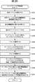
- FIG. 1 shows a reference relation for creating a predicted image for compression in consideration of spatial scalability in SVC.
- the base layer and the enhancement layer shown in FIG. 1 are encoded at a plurality of resolutions.
- an image (N, M is an integer, N> n and M> m) having a resolution of N ⁇ M [pix] as an enhancement layer is encoded using spatial scalability.
- encoding of the current frame is performed using intra prediction or inter prediction as in the case of the H.264 standard.
- two reference planes Ref0, Ref1
- motion compensated images MC0, MC1 from each reference plane are extracted to perform inter prediction.
- encoding of the current frame can be performed using intra prediction or inter prediction as in the case of the base layer.
- Intra prediction is effective when there is a small amount of correlation in the temporal direction, such as a small amount of subject motion, in a moving image to be encoded, but in a general moving image, correlation in the temporal direction is usually better than spatial direction prediction. Is often higher and is not optimal from the viewpoint of coding efficiency.
- inter prediction the decoded image in the enhancement layer of the temporally preceding or succeeding frame is used as the reference plane.
- Inter prediction enables the realization of high coding efficiency because it uses correlation in the time direction.
- upconversion prediction a prediction method based on spatial upsampling (upconversion) of the base layer in addition to these two methods for encoding the current frame.
- the image of the base layer is obtained by reducing the resolution of the image of the enhancement layer, it can be considered that a signal corresponding to the low frequency component of the image of the enhancement layer is included. That is, the image of the enhancement layer can be obtained by supplementing the image of the base layer with the high frequency component.
- Upconversion prediction is a method of performing prediction using such correlation between layers. It is a prediction method that is useful for improving coding efficiency, particularly when intra or inter prediction does not occur. Further, with this prediction method, it is sufficient to decode the image of the base layer at the same time to decode the image of the enhancement layer of the current frame, so it can be said that this prediction method is excellent (small load) from the viewpoint of processing amount. .
- Non-Patent Document 1 correlation in the time direction is used for the resolution enhancement process on an input image sequence. Specifically, the difference information of the motion predicted / compensated image is calculated between the current image and the past image, and the high frequency component included in the input image is restored by feedback to the current image of interest. .
- Non-Patent Document 1 it is conceivable to apply an image processing method for converting temporal correlation of a moving image to a spatial resolution as described in Non-Patent Document 1 to realize improvement in coding efficiency.
- the method described in Non-Patent Document 1 could not simply be applied to SVC.
- the resolutions of the motion compensated image obtained from the reference plane and the predicted image generated are the same, and the method described in Non-Patent Document 1 can not be applied to upconversion prediction.
- the method described in Non-Patent Document 1 for performing resolution enhancement using three images is applied to upconversion prediction I could not do that.
- the present invention has been proposed in view of such a situation, and in performing coding in consideration of spatial scalability, it is possible to more efficiently use temporal correlation included in a moving image signal sequence, for example, It is possible to improve coding efficiency while suppressing an increase in processing load such as quantization and decoding.
- One aspect of the present invention includes a decoding unit that decodes a coded image, a generation unit that adds the image decoded by the decoding unit and a predicted image to generate a decoded image, and the generation unit
- the motion compensation is performed using the encoded motion vector of the image with the frame including the generated decoded image as a reference frame, and the motion compensated image having a resolution lower than that of the predicted image corresponds to the predicted image.
- an estimated image generation unit configured to generate the estimated image having a resolution higher than that of the motion compensated image.
- the encoded image is hierarchically encoded into a plurality of layers having different resolutions, and the decoding unit decodes the encoded image in each layer, and the generation unit
- the decoded image is generated in a layer, and the extraction unit determines the frame of a layer having a resolution lower than that of the layer as the reference frame when decoding the layer having a high resolution, the reference frame including the low resolution layer.
- the motion compensated image is extracted from a reference frame, and the predicted image generation unit performs the filtering process on the motion compensated image extracted from the reference frame of the low resolution layer to obtain the high resolution
- the predicted image of a layer can be generated.
- the predicted image generation unit converts the resolution of the difference image of the plurality of motion compensated images extracted by the extraction unit, and performs resolution enhancement, and the difference whose resolution is enhanced by the resolution conversion unit
- adding means for adding to any one to generate the predicted image.
- the addition means is an image obtained by applying the low pass filter by the first filter means to the motion compensated image extracted from the frame one time before on the basis of the time of the predicted image; An image obtained by applying the high pass filter by the second filter means can be added.
- Bidirectional prediction is performed using a plurality of motion compensated images and unidirectional prediction is performed using a plurality of motion compensated images, and bidirectional prediction is performed using a plurality of motion compensated images to generate the predicted image Whether the predicted image is generated by unidirectional prediction by the unidirectional prediction unit or by bidirectional prediction by the bidirectional prediction unit is performed by the prediction unit and the identification flag included in the header of the encoded image
- the image processing apparatus may further include determination means for determining whether the image is to be generated by the filtering process by the predicted image generation means.
- One aspect of the present invention also decodes a coded image, adds the decoded image and the predicted image, generates a decoded image, and refers to a frame consisting of the generated decoded image as a frame
- Motion compensation is performed using a motion vector of the encoded image, and a motion compensated image having a resolution lower than that of the predicted image is extracted from the reference frame corresponding to the predicted image, and the extracted motion is extracted.
- An image processing method for generating the predicted image having a resolution higher than that of the motion compensated image by performing a filtering process on the compensated image to compensate for high frequency components by using correlation in the time direction included in the motion compensated image. It is.
- Another aspect of the present invention is based on encoding means for encoding an original image to be encoded and generating an encoded image, and a residual signal indicating a difference between the original image and the predicted image.
- Detection means for detecting a motion vector based on an image obtained by locally decoding the image and the original image, and the detection means using a frame consisting of the image obtained by locally decoding as a reference frame
- Extracting means for performing motion compensation using the motion vector detected by the method, and extracting a motion compensated image having a resolution lower than that of the predicted image from the reference frame corresponding to the predicted image;
- An image processing apparatus comprising generating means for generating a serial prediction image.
- the encoding means generates an image encoded in a plurality of layers having different resolutions
- the extraction means generates the frame of the layer having a resolution lower than that of the layer when decoding the high resolution layer.
- the motion compensated image is extracted from the reference frame of the low resolution layer using the motion vector detected in the low resolution layer by the detection unit as the reference frame, and the generation unit is configured to
- the prediction process of the high resolution layer can be generated by performing the filtering process on the motion compensated image extracted from the reference frame of the resolution layer.
- the generation unit converts the resolution of the difference image of the plurality of motion compensated images extracted by the extraction unit, and converts the resolution of the difference image into high resolution, and the difference image high resolution converted by the resolution conversion unit
- adding means for generating the predicted image.
- the addition means is an image obtained by applying the low pass filter by the first filter means to the motion compensated image extracted from the frame one time before on the basis of the time of the predicted image; An image obtained by applying the high pass filter by the second filter means can be added.
- the encoding means identifies an identification flag identifying whether to generate a predicted image to be added to the image decoded by the decoding device by one-way prediction, bidirectional prediction, or the filtering process. It can be included in the header.
- Another aspect of the present invention is also to encode an original image which is an image to be encoded, generate an encoded image, and locally based on a residual signal indicating a difference between the original image and a predicted image.
- the motion vector is detected on the basis of the image obtained by decoding the image and the original image, and a motion is generated using the detected motion vector, using a frame consisting of the image obtained by Compensation is performed, and a motion compensated image having a resolution lower than that of the predicted image is extracted from the reference frame corresponding to the predicted image, and a time direction included in the motion compensated image with respect to the extracted motion compensated image
- the image processing method is configured to generate the predicted image with a resolution higher than that of the motion compensated image by performing filtering processing for compensating high frequency components using the correlation of
- a coded image is decoded, the decoded image and a predicted image are added, a decoded image is generated, and a frame consisting of the generated decoded image is referred to as a frame.
- the motion vector of the encoded image is used to perform motion compensation, and a motion-compensated image with a lower resolution than the predicted image is extracted from the reference frame corresponding to the predicted image, and the extracted motion-compensated image is By performing filtering processing to compensate for high frequency components using the correlation in the time direction included in the motion compensated image, a predicted image with a higher resolution than that of the motion compensated image is generated.
- an original image which is an image to be encoded is encoded to generate an encoded image, and a local signal is generated based on a residual signal indicating a difference between the original image and a predicted image.
- Motion vector is detected on the basis of the image obtained by decoding the image and the original image, and the motion compensation is performed using the detected motion vector with the frame consisting of the image obtained by the local decoding as the reference frame.
- the motion compensated image having a resolution lower than that of the predicted image is extracted from the reference frame corresponding to the predicted image, and the extracted motion compensated image is correlated with the high frequency using the correlation in the time direction included in the motion compensated image.
- information can be processed.
- it is possible to generate a highly accurate predicted image and improve coding efficiency without unnecessarily increasing the load.
- FIG. 2 is a diagram for explaining an outline of a predicted image generation method to which the present invention is applied.
- the prediction image of the current block (processing target block at the current time) in the enhancement layer is generated by filtering the images of the plurality of reference planes in the base layer.
- the predicted image generated by the method of the present invention (hereinafter referred to as filtering prediction) is a predicted image generated by the conventional up-conversion prediction using the image of the current frame of the base layer (the processing target frame at the current time). It is possible to reduce the prediction residual while having spatially higher frequency components. That is, the code amount of the coded picture in the enhancement layer can be reduced, which can contribute to the improvement of the coding efficiency.
- the processing amount required for encoding, the temporary storage capacity, the amount of information read from memory, etc. can be reduced. Costs can be reduced. In addition, power consumption can be reduced.
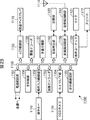
- FIG. 3 is a block diagram showing a configuration example of the decoding device 1 according to an embodiment of the present invention.
- Image information encoded by an encoding device described later is input to the decoding device 1 via a cable, a network, or a removable medium.
- the compressed image information is, for example, image information encoded according to the H.264 / SVC standard.
- compressed image information is composed of layers of multiple resolutions.
- the lowest resolution layer is the base layer, and the higher resolution layer than the base layer is the enhancement layer.
- the number of layers is arbitrary, it is assumed that compressed image information is composed of two layers in the following. That is, the compressed image information input to the decoding device 1 includes the base layer and one enhancement layer.
- the compressed image information of each frame is sequentially input to the decoding device 1.
- the bit stream of each layer is sequentially input from the low resolution side to the high resolution side. That is, the bitstream of the base layer is input to the decoding device 1 first.
- the bit stream of the base layer is decoded in the same manner as in the case of compressed image information of the H.264 / AVC standard, so the description thereof is omitted here.
- the decoder 1 receives the bitstream of the enhancement layer. In the following, basically, processing on the enhancement layer bit stream will be described.
- the accumulation buffer 11 sequentially stores bit streams input as compressed image information.
- the information stored in the accumulation buffer 11 is appropriately read by the lossless decoding circuit 12 for each image of a predetermined unit such as a macro block forming a frame.
- processing can be performed not in units of macroblocks of 16 ⁇ 16 pixels, but in units of blocks such as 8 ⁇ 8 pixels, 4 ⁇ 4 pixels, etc.
- the lossless decoding circuit 12 subjects the image read from the accumulation buffer 11 to decoding processing corresponding to a coding method such as variable length decoding processing and arithmetic decoding processing.
- the lossless decoding circuit 12 outputs the quantized transform coefficient obtained by performing the decoding process to the inverse quantization circuit 13.
- the lossless decoding circuit 12 identifies the prediction method based on the identification flag included in the header of the image to be decoded.
- the lossless decoding circuit 12 determines that the image to be decoded is an intra-coded image
- the lossless decoding circuit 12 outputs the intra prediction mode information stored in the header of the image to the intra prediction circuit 22.
- the intra prediction mode information includes information on intra prediction such as the size of a block serving as a processing unit.
- the lossless decoding circuit 12 When the lossless decoding circuit 12 determines that the image to be decoded is inter-coded information, the lossless decoding circuit 12 outputs the motion vector and the identification flag stored in the header of the image to the motion prediction / compensation circuit 21. Do.
- the identification flag identifies the mode of prediction when generating a predicted image by inter prediction.
- the identification flag is set, for example, in units of macroblocks and in units of frames.
- a mode of prediction in addition to a mode of one-way prediction, a mode of bi-directional prediction, a mode of up-conversion prediction, a motion compensated image extracted from a plurality of reference frames temporally or bi-directionally in the base layer
- a filtering prediction mode is provided in which filtering is performed to generate a prediction image.
- a prediction mode in which a pixel value of one of motion compensated images extracted from a plurality of reference frames in one direction is a pixel value of a predicted image is simply referred to as a unidirectional prediction mode.
- a prediction mode in which an average value of pixel values of a motion compensated image extracted from each of a plurality of reference frames present in both directions is used as a pixel value of a predicted image is simply referred to as a bidirectional prediction mode.
- a mode of prediction in which a motion compensated image extracted from a current frame of a base layer is upconverted to obtain a pixel value of a predicted image is simply referred to as an upconversion prediction mode.
- a fourth method as shown in FIG. 2 for performing filtering including up conversion on each motion compensated image extracted from a plurality of reference frames in one direction or both directions of the base layer to obtain pixel values of a predicted image.
- the mode of prediction is called filtering prediction mode.
- the dequantization circuit 13 dequantizes the transform coefficient in the quantized state supplied from the lossless decoding circuit 12 using a method corresponding to the quantization method on the encoding side.
- the inverse quantization circuit 13 outputs the transform coefficient obtained by performing the inverse quantization to the inverse orthogonal transform circuit 14.
- the inverse orthogonal transformation circuit 14 is a system corresponding to the orthogonal transformation system on the encoding side, such as discrete cosine transformation and Karhunen-Loeve transformation, for example, the fourth-order inverse orthogonal transformation to the transformation coefficient supplied from the inverse quantization circuit 13
- the obtained image is output to the addition circuit 15.
- the addition circuit 15 combines the decoded image supplied from the inverse orthogonal transformation circuit 14 with the predicted image supplied from the motion prediction / compensation circuit 21 or from the intra prediction circuit 22 via the switch 23 to Output to block filter 16.
- the deblocking filter 16 removes block distortion contained in the image supplied from the addition circuit 15, and outputs an image from which the block distortion has been removed.
- the image output from the deblocking filter 16 is supplied to the reordering buffer 17 and the frame memory 19.
- the rearrangement buffer 17 temporarily stores the image supplied from the deblocking filter 16.
- the rearrangement buffer 17 generates each frame from the stored image, for example, in units of macroblocks, rearranges the generated frames in a predetermined order such as display order, and the like to a D / A (Digital / Analog) conversion circuit 18. Output.
- the D / A conversion circuit 18 performs D / A conversion on each frame supplied from the rearrangement buffer 17 and outputs the signal of each frame to the outside.
- the frame memory 19 temporarily stores the image supplied from the deblocking filter 16.
- the information stored in the frame memory 19 is supplied to the motion prediction / compensation circuit 21 or the intra prediction circuit 22 through the switch 20.
- the frame memory 19 also stores an image of the base layer decoded earlier than the enhancement layer, and is used for decoding of the enhancement layer as described later.
- the switch 20 is connected to the terminal a1 when generating a predicted image by inter prediction, and is connected to the terminal b1 when generating by intra prediction.
- the switching of the switch 20 is controlled by the control circuit 31, for example.
- the motion prediction / compensation circuit 21 determines the prediction mode in accordance with the identification flag supplied from the lossless decoding circuit 12 and selects one of the decoded frames stored in the frame memory 19 as a reference frame in the prediction mode. Choose accordingly.
- the motion prediction / compensation circuit 21 determines a macroblock corresponding to the target predicted image from among the macroblocks constituting the reference frame based on the motion vector supplied from the lossless decoding circuit 12 and determines the determined macroblock. Is extracted as a motion compensated image.
- the motion prediction / compensation circuit 21 obtains the pixel value of the predicted image from the pixel value of the motion compensated image according to the prediction mode, and outputs the predicted image for which the pixel value is obtained to the addition circuit 15 via the switch 23.
- the intra prediction circuit 22 performs intra prediction in accordance with the intra prediction mode information supplied from the lossless decoding circuit 12 and generates a predicted image.
- the intra prediction circuit 22 outputs the generated predicted image to the addition circuit 15 via the switch 23.
- the switch 23 is connected to the terminal a2 when a predicted image is generated by the motion prediction / compensation circuit 21 and connected to the terminal b2 when a predicted image is generated by the intra prediction circuit 22.
- the switching of the switch 23 is also controlled by the control circuit 31, for example.
- the control circuit 31 controls the entire operation of the decoding device 1 by switching the connection of the switches 20 and 23 or the like.
- the identification of the prediction method of the image to be processed may be performed by the control circuit 31.
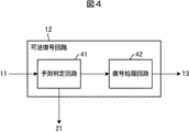
- FIG. 4 is a block diagram showing an example of the main configuration of the lossless decoding circuit 12 of FIG.
- the lossless decoding circuit 12 includes a prediction determination circuit 41 and a decoding processing circuit 42.
- the prediction judgment circuit 41 judges the prediction method of the image supplied from the accumulation buffer 11.
- the prediction determination circuit 41 identifies the prediction method based on, for example, an identification flag included in the header of the image to be decoded.
- the prediction determination circuit 41 may identify this prediction method by analyzing the bit stream. In this case, since the identification flag can be omitted, the amount of compressed image information can be reduced.
- the prediction determination circuit 41 determines that the image to be decoded is an intra-coded image
- the prediction determination circuit 41 outputs the intra prediction mode information stored in the header of the image to the intra prediction circuit 22.
- the motion prediction / compensation circuit 21 stores the motion vector and the identification flag stored in the header of the image.
- the prediction determination circuit 41 further supplies the bit stream of the image for which the prediction method has been determined to the decoding processing circuit 42.
- the decoding processing circuit 42 applies, to the image, decoding processing corresponding to a coding method, such as variable length decoding processing and arithmetic decoding processing.
- the prediction determination circuit 41 outputs the quantized transform coefficient obtained by performing the decoding process to the inverse quantization circuit 13.
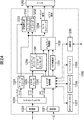
- FIG. 5 is a block diagram showing an example of the main configuration of the motion prediction / compensation circuit of FIG.
- the motion prediction / compensation circuit 21 includes a prediction selection circuit 51, a one-way prediction circuit 61, a bidirectional prediction circuit 62, an upconversion prediction circuit 63, and a filtering prediction circuit 64.
- the motion vector and the identification flag supplied from the lossless decoding circuit 12 (prediction determination circuit 41) are input to the prediction selection circuit 51.
- the prediction selection circuit 51 selects the prediction mode in accordance with the identification flag supplied from the prediction determination circuit 41.
- the prediction selection circuit 51 outputs a motion vector to the one-way prediction circuit 61 when it is determined to generate a predicted image by one-way prediction. Further, the prediction selection circuit 51 outputs a motion vector to the bidirectional prediction circuit 62 when it is determined to generate a predicted image by bidirectional prediction. Furthermore, when it is determined to generate a predicted image by upconversion prediction, the prediction selection circuit 51 outputs the instruction to the upconversion prediction circuit 63.
- the prediction selection circuit 51 outputs the motion vector to the filtering prediction circuit 64 when it is determined to generate a prediction image by filtering prediction.
- the unidirectional prediction circuit 61 uses a plurality of frames in one direction in the temporal direction of the enhancement layer as a reference frame, and determines macroblocks of the reference frame corresponding to the predicted image based on the motion vector. In addition, the unidirectional prediction circuit 61 reads the macroblocks of the determined reference frames from the frame memory 19 as a motion compensated image, and uses the pixel value of any motion compensated image as the pixel value of the predicted image to predict the predicted image. Generate The one-way prediction circuit 61 outputs the generated predicted image to the addition circuit 15. As one-way prediction by the one-way prediction circuit 61, for example, one-way prediction defined by the H.264 / SVC standard (or H.264 standard) is used.
- the bi-directional prediction circuit 62 determines a plurality of frames that are bi-directionally in the enhancement layer as reference frames, and determines a macroblock of the reference frame corresponding to the predicted image based on the motion vector. Also, the bidirectional prediction circuit 62 reads the macroblocks of the determined reference frames from the frame memory 19 as a motion compensated image, and predicts the average of the pixel values of the read motion compensated image as the pixel value of the predicted image. Generate an image. The bidirectional prediction circuit 62 outputs the generated predicted image to the addition circuit 15. As bidirectional prediction by the bidirectional prediction circuit 62, for example, bidirectional prediction defined by the H.264 / SVC standard (or H.264 standard) is used.
- the upconversion prediction circuit 63 uses the current frame of the base layer as a reference frame as shown in FIG.
- the upconversion prediction circuit 63 extracts, from the reference frame of the base layer, a macroblock at the same position as the processing target macroblock of the current frame of the enhancement layer. That is, the upconversion prediction circuit 63 reads from the frame memory 19 the macroblock corresponding to the processing target macroblock of the reference frame of the base layer. Since the extracted macroblock is a macroblock of the base layer, the resolution of the macroblock to be processed is low.
- the upconversion prediction circuit 63 upconverts the extracted macroblocks of the base layer to generate a predicted image of the macroblock to be processed.
- the up-conversion prediction circuit 63 outputs the generated predicted image to the addition circuit 15.
- upconversion prediction circuit 63 for example, upconversion prediction specified in the H.264 / SVC standard is used.
- the filtering prediction circuit 64 determines, as a reference frame, a plurality of frames in one direction or two directions in time of the base layer as shown in FIG. Which frame is to be used as a reference frame may be determined in advance, or may be specified by information transmitted from the encoding side together with an identification flag. For example, two frames located one time before the current frame and one time before the current frame may be used as reference frames. Also, for example, two frames located one time before and one time after the current frame may be used as reference frames. Of course, this other frame may be used as a reference frame.
- the filtering prediction circuit 64 determines, based on the motion vector supplied from the prediction selection circuit 51, the macroblock corresponding to the prediction image of the reference frame of the base layer determined as described above.
- the filtering prediction circuit 64 reads the determined macroblocks of each reference frame from the frame memory 19 as a motion compensated image.
- the motion vector may not be performed in units of macro blocks such as 16 ⁇ 16 pixels, but may be performed in units of blocks obtained by further dividing the macro block.
- Filtering prediction circuit 64 receives this motion compensated image as input, performs filtering with up conversion, and outputs a predicted image obtained by performing filtering to addition circuit 15. The predicted image is upconverted to the resolution of the enhancement layer macroblock.
- the filtering prediction circuit 64 outputs the generated predicted image to the addition circuit 15.
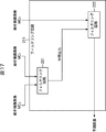
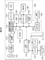
- FIG. 6 is a block diagram showing an example of the main configuration of the filtering prediction circuit 64 of FIG.
- the filtering prediction circuit 64 having the configuration of FIG. 6 applies filtering to the time domain signal.
- the filtering prediction circuit 64 includes an extraction circuit 71 and a filtering circuit 72.
- the extraction circuit 71 specifies the reference frame of the base layer based on the information supplied from the prediction selection circuit 51, and the motion compensated image (for example, the motion compensated image MC0 and the motion compensated image MC1) from the reference frame of the base layer. Extract.
- the decoded image at the same position is used as the first input, and as the second input, the image uses the low resolution in the past or future in the temporal prediction used for temporal prediction Two of the images are the input for the subsequent filtering process.
- the extraction circuit 71 sets a macro block at the same position as the processing target macro block of the enhancement layer in the current frame of the base layer as one motion compensation image, and further uses it when decoding the macro block of the base layer. Another motion compensated image is extracted using the selected motion vector.
- this method is effective because the more highly correlated temporal information is used, the higher the resolution generated in the subsequent filtering process.
- a new motion vector is encoded for the enhancement layer decoding separately from the motion vector used at the time of the base layer decoding.
- the extraction circuit 71 specifies the motion compensation image MC0 and the motion compensation image MC1 as described above, and acquires the information from the frame memory 19.
- the extraction circuit 71 supplies the extracted motion compensated image MC0 and motion compensated image MC1 to the filtering circuit 72.
- the filtering circuit 72 performs filtering with up conversion on the supplied motion compensated image MC0 and motion compensated image MC1 to generate a predicted image.
- the filtering circuit 72 performs a filtering process on the plurality of motion compensated images extracted by the extracting circuit 71 by using a correlation in the time direction included in the motion compensated image to compensate for high frequency components. Generate a predicted image of higher resolution than the compensated image.
- the prediction image generated in this manner has its high frequency component compensated, so the prediction accuracy is improved. As a result, coding efficiency is improved.
- the filtering circuit 72 is, as shown in FIG. 6, a difference calculating circuit 81, an up converting circuit 82, a low pass filter circuit 83, a gain adjusting circuit 84, a high pass filter circuit 85, a gain adjusting circuit 86, an adding circuit 87, an up converting circuit 88 and an adder circuit 89.
- the motion compensated image MC0 supplied from the extracting circuit 71 is input to the difference calculating circuit 81 and the up converting circuit 88, and the motion compensated image MC1 is input to the difference calculating circuit 81.
- an image extracted from a reference frame R0 close to the current frame, which is considered to have a high correlation with the predicted image is regarded as a motion compensated image MC0
- An image extracted from the frame R1 is a motion compensated image MC1.
- An image extracted from the reference frame R0 may be a motion compensated image MC1
- an image extracted from the reference frame R1 may be a motion compensated image MC0.
- an image extracted from the reference frame L0 one time before is regarded as a motion compensated image MC0
- an image extracted from the reference frame L1 one time later is motion compensated It is assumed that the image MC1.
- An image extracted from the reference frame L0 may be a motion compensated image MC1
- an image extracted from the reference frame L1 may be a motion compensated image MC0.
- the difference calculation circuit 81 calculates the difference between the motion compensated image MC0 and the motion compensated image MC1 according to, for example, the following equation (1), and outputs the difference image D to the up conversion circuit 82.
- (i, j) represents the relative position of the pixel in the motion compensated image.
- i, j represents the relative position of the pixel in the motion compensated image.
- the up-conversion circuit 82 converts the resolution of the difference image D calculated by the difference calculation circuit 81.
- This resolution conversion ratio is based on the ratio of the spatial resolution of the base layer and the enhancement layer. For example, when the resolution of the base layer is n ⁇ m [pixel] (n, m is an integer) and the enhancement layer is N ⁇ M [pixel] (N and M are integers and N> n, M> m), the horizontal direction
- the magnification H_Scale of and the magnification V_Scale in the vertical direction are expressed by Equation (2) and Equation (3).
- the up conversion circuit 82 outputs the difference image D ′ thus resolution converted (up converted) to the low pass filter circuit 83.
- the low pass filter circuit 83 has an FIR filter circuit.
- the low pass filter circuit 83 applies a low pass filter to the difference image D ′ supplied from the up conversion circuit 82, and outputs the obtained image to the gain adjustment circuit 84 and the high pass filter circuit 85.
- the difference image D ′ ′ which is an image obtained by applying a low pass filter, is expressed by the following equation (4).
- the LPF (X) in Equation (4) represents that the input image X is low-pass filtered using a two-dimensional FIR filter.
- the gain adjustment circuit 84 adjusts the gain of the difference image D ′ ′ supplied from the low pass filter circuit 83, and outputs the image whose gain has been adjusted to the addition circuit 87. Assuming that 0 ⁇ I ⁇ 16 ⁇ H_Scale and 0 ⁇ J ⁇ 16 ⁇ V_Scale, an output image X (I, J) of the gain adjustment circuit 84 is expressed as the following equation (5).
- the high pass filter circuit 85 has an FIR filter circuit.
- the high pass filter circuit 85 applies a high pass filter to the difference image D ′ ′ supplied from the low pass filter circuit 83, and outputs the obtained image to the gain adjustment circuit 86.
- the differential image D ′ ′ ′ which is an image obtained by applying a high-pass filter, is expressed by the following equation (6).
- the HPF (X) in Equation (6) indicates that the input image X is subjected to high-pass filtering with a two-dimensional FIR filter.
- the gain adjustment circuit 86 adjusts the gain of the difference image D ′ ′ ′ supplied from the high pass filter circuit 85, and outputs the image whose gain has been adjusted to the addition circuit 87.
- An output image Y (I, J) of the gain adjustment circuit 86 is expressed as the following equation (7).
- the adder circuit 87 adds the gain-adjusted image X (I, J) and the image Y (I, J), and outputs an image obtained by the addition.
- the output image Z (I, J) of the adding circuit 87 is expressed as the following equation (8).
- the output image Z (I, J) represents the difference between the motion compensated image MC0 and the motion compensated image MC1, that is, the high frequency component of the image obtained from the correlation.
- the up conversion circuit 88 converts the resolution of the motion compensated image MC0. As in the case of the up conversion circuit 82, this resolution conversion ratio is based on the ratio of the spatial resolutions of the base layer and the enhancement layer. That is, the magnification H_Scale in the horizontal direction and the magnification V_Scale in the vertical direction are expressed by the above-mentioned equations (2) and (3).
- the up conversion circuit 88 outputs the image A ′, which is the motion-compensated image MC0 thus resolution converted (up converted), to the addition circuit 89.
- the adder circuit 89 adds the output image Z (I, J) supplied from the adder circuit 87 to the image A ′ supplied from the up-conversion circuit 88, and uses the obtained image as a predicted image.
- Output to The predicted image S (I, J), which is the final output of the adding circuit 89, is represented by the following equation (9).
- a predicted image is generated by adding an image representing a high frequency component generated by up-converting the image of the base layer to an image in which the motion compensated image MC0 is up-converted. Be done.
- the decoding device 1 By generating the prediction image in the filtering prediction mode as described above, the decoding device 1 includes more high frequency components than the prediction image of upconversion prediction obtained by upconverting the image of the current frame of the base layer. A predicted image can be obtained.
- the decoding device 1 since the filtering is performed as described above when generating a prediction image from a plurality of motion compensated images, the decoding device 1 simply uses the average value of each pixel of the plurality of motion compensated images as each pixel value. It is possible to obtain a predicted image including more high frequency components than the predicted image.
- the resolution of the image to be referred to is smaller than in the case of inter prediction in which the prediction image is generated with reference to the frames of the enhancement layer. Therefore, it is not necessary to store or read the high resolution image of the enhancement layer in the frame memory 19.
- the information at the time of decoding of the base layer can be used at the time of decoding of the enhancement layer like, for example, a motion vector, the code amount of compressed image information can be reduced. That is, the decoding device 1 can improve the compression efficiency.
- the decoding device 1 can improve the coding efficiency while suppressing an increase in load.
- enhancement layer decoding processing there is a mode in which an image of the base layer at the same time is used to generate a predicted image, which is largely different from the base layer decoding processing and the H.264 standard. Furthermore, in the case of the enhancement layer decoding process to which the present invention is applied, a function is used in which a plurality of images of the base layer at the same time or at different times in time as the current frame are used for the enhancement layer decoding.
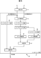
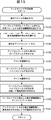
- the process of FIG. 9 is started, for example, when an image of a predetermined size such as a macro block of 16 ⁇ 16 pixels is read by the lossless decoding circuit 12 from information stored in the accumulation buffer 11.
- the processing of each step in FIG. 9 is appropriately performed in parallel with the processing of the other steps or in a different order from the other steps. The same applies to the processing of each step in each flowchart to be described later.
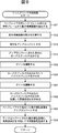
- step S ⁇ b> 1 the lossless decoding circuit 12 starts the lossless decoding process on the image read from the accumulation buffer 11. Details of the lossless decoding process will be described later.
- the lossless decoding circuit 12 outputs the quantized transform coefficient generated by the lossless decoding process to the dequantization circuit 13. Further, in the case where the image to be decoded is an intra-coded image in the lossless decoding process, the lossless decoding circuit 12 outputs intra prediction mode information to the intra prediction circuit 22 and is an inter-coded image.
- the motion vector and the identification flag are output to the motion prediction / compensation circuit 21.
- step S ⁇ b> 2 the inverse quantization circuit 13 performs inverse quantization according to a method corresponding to the quantization method on the encoding side, and outputs transform coefficients to the inverse orthogonal transformation circuit 14.
- step S 3 the inverse orthogonal transformation circuit 14 performs inverse orthogonal transformation on the transform coefficient supplied from the inverse quantization circuit 13, and outputs the obtained image to the addition circuit 15.
- step S4 the addition circuit 15 combines the decoded image supplied from the inverse orthogonal transformation circuit 14 with the predicted image supplied from the motion prediction / compensation circuit 21 or from the intra prediction circuit 22 to deblock the synthesized image. Output to the filter 16.
- the deblocking filter 16 performs filtering to remove block distortion contained in the composite image, and outputs an image from which block distortion has been removed.
- the frame memory 19 temporarily stores the image supplied from the deblocking filter 16. At this time, the image is also held in the reordering buffer 17.
- step S7 the control circuit 31 determines whether or not the above processing has been performed for the macroblock of the entire one frame, and when it is determined that the processing has not been performed, attention is paid to other macroblocks. Repeat the process of
- step S7 If it is determined in step S7 that the process has been performed on the macroblock of the entire one frame, the process proceeds to step S8.
- step S ⁇ b> 8 the rearrangement buffer 17 outputs the generated frame to the D / A conversion circuit 18 under the control of the control circuit 31.
- step S9 the D / A conversion circuit 18 performs D / A conversion on the frame supplied from the rearrangement buffer 17, and outputs an analog signal to the outside. The above processing is performed for each frame.
- the prediction determination circuit 41 refers to the header of the compressed image information supplied from the accumulation buffer 11 in step S21. In step S22, the prediction determination circuit 41 determines whether or not to perform intra prediction based on the information indicating the prediction mode specified by the encoding device, which is included in the header. When the intra prediction mode is designated by the encoding device, the processing proceeds to step S23.
- step S23 the intra prediction circuit 22 performs intra prediction to generate a prediction image, and supplies the prediction image to the addition circuit 15. This predicted image is combined with the decoded image supplied from the inverse orthogonal transformation circuit 14 in step S4 of FIG.
- step S23 When the process of step S23 ends, the process proceeds to step S29. If it is determined in step S22 that intra prediction is not to be performed, the process proceeds to step S24.
- step S24 the prediction determination circuit 41 determines whether to perform upconversion prediction based on the information indicating the prediction mode specified by the encoding device, which is included in the header.
- the processing proceeds to step S25.
- step S25 the upconversion prediction circuit 63 of the motion prediction / compensation circuit 21 performs upconversion prediction to generate a prediction image, and supplies the prediction image to the addition circuit 15. This predicted image is combined with the decoded image supplied from the inverse orthogonal transformation circuit 14 in step S4 of FIG.
- step S25 When the process of step S25 ends, the process proceeds to step S29. If it is determined in step S24 that upconversion prediction is not to be performed, the process proceeds to step S26.
- step S26 the prediction determination circuit 41 determines whether to perform inter prediction based on the information indicating the prediction mode specified by the encoding device, which is included in the header.
- the processing proceeds to step S27.
- step S27 the one-way prediction circuit 61 or the two-way prediction circuit 62 of the motion prediction / compensation circuit 21 performs inter prediction (one-way prediction or two-way prediction) to generate a predicted image, and adds the predicted image Supply to 15. This predicted image is combined with the decoded image supplied from the inverse orthogonal transformation circuit 14 in step S4 of FIG.
- step S27 When the process of step S27 ends, the process proceeds to step S29.
- step S26 when the filtering prediction mode is designated by the encoding apparatus and it is determined that inter prediction is not performed, the processing proceeds to step S28.
- step S28 the filtering prediction circuit 64 of the motion prediction / compensation circuit 21 performs filtering prediction based on the information indicating the filtering prediction mode included in the header to generate a predicted image, and adds the predicted image to the adding circuit 15 Supply to This predicted image is combined with the decoded image supplied from the inverse orthogonal transformation circuit 14 in step S4 of FIG.
- step S29 the filtering prediction circuit 64 of the motion prediction / compensation circuit 21 performs filtering prediction based on the information indicating the filtering prediction mode included in the header to generate a predicted image, and adds the predicted image to the adding circuit 15 Supply to This predicted image is combined with the decoded image supplied from the inverse orthogonal transformation circuit 14 in step S4 of FIG.
- step S29 the decoding processing circuit 42 decodes the residual signal of the compressed image information, and outputs the quantized transform coefficient to the inverse quantization circuit 13.
- the process of step S29 ends the lossless decoding process ends, the process returns to step S1 of FIG. 7, and the processes of step S2 and subsequent steps are performed.
- the prediction mode is selected based on the information contained in the header of the compressed image information referred to in step S21.
- the present invention is not limited to this, and the prediction determination circuit 41 may be able to select an appropriate prediction mode, for example, by analyzing a bit stream of compressed image information. In that case, in step S21, the prediction determination circuit 41 analyzes the compressed image information instead of referring to the header, and selects the prediction mode based on the analysis result by the processing in step S22 and subsequent steps.
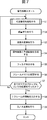
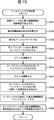
- the extraction circuit 71 extracts a motion compensated image from the current frame or the reference frame from the base layer in step S41.
- the difference calculation circuit 81 calculates the difference of the motion compensated image in step S42.
- the up-conversion circuit 82 up-converts the motion-compensated image difference calculated in step S42.
- the low pass filter circuit 83 applies a low pass filter to the up-converted difference in step S43.
- step S45 the gain adjustment circuit 84 performs gain adjustment by multiplying the output of the low-pass filter in the process of step S44 by the coefficient ⁇ .
- step S46 the high pass filter circuit 85 applies a high pass filter to the output of the low pass filter in the process of step S44.
- step S47 the gain adjustment circuit 86 performs gain adjustment by multiplying the output of the high-pass filter in the process of step S46 by the coefficient ⁇ .
- step S48 the adding circuit 87 adds the output of the low pass filter whose gain is adjusted in the process of step S45 and the output of the high pass filter whose gain is adjusted in the process of step S47 to obtain a high frequency component.
- step S49 the up-conversion circuit 88 up-converts the motion compensated image MC0 extracted from the base layer.
- step S50 the adding circuit 89 adds the high frequency component obtained in step S48 to the motion compensated image up-converted in step S49 to generate a predicted image.
- the addition circuit 89 supplies the generated predicted image to the addition circuit 15.
- step S50 When the process of step S50 ends, the filtering prediction process ends, the process returns to step S28 of FIG. 8, and the processes of step S29 and subsequent steps are performed.
- decoding is performed using a predicted image generated by filtering prediction, so that a high-definition decoded image can be obtained without increasing the processing load. That is, the decoding device 1 can improve the coding efficiency while suppressing an increase in load.
- the present invention is not limited to this, and the decoding of both may be performed in different decoding devices 1 Good.
- the frame memory 19 is common to all the decoding devices, and the base layer frame can be read out when the enhancement layer is decoded.
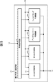
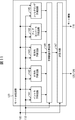
- FIG. 10 is a block diagram showing a main configuration example of a coding device to which the present invention is applied.
- the encoding apparatus 101 is an encoding apparatus corresponding to the decoding apparatus 1 of FIG. That is, compressed image information obtained by being encoded by the encoding device 101 is input to the decoding device 1 of FIG.
- the encoding apparatus 101 includes an A / D conversion circuit 111, a rearrangement buffer 112, an addition circuit 113, an orthogonal transformation circuit 114, a quantization circuit 115, a lossless encoding circuit 116, and a storage buffer 117.
- the encoding apparatus 101 further includes a rate control circuit 118, an inverse quantization circuit 119, an inverse orthogonal transformation circuit 120, a deblocking filter 121, a frame memory 122, and a mode determination circuit 123.
- the encoding device 101 includes a switch 124, a motion prediction / compensation circuit 125, an intra prediction circuit 126, a switch 127, and a control circuit 131.
- the image information is bi-layered (or multi-layered into three or more layers) in a low resolution base layer and a high resolution enhancement layer, and the image information of each frame is encoded from the low resolution base layer first. Is supplied and encoded.
- This base layer coding is performed as in the case of the H.264 standard.
- the image information of the enhancement layer is coded by the coding device 101.
- the coding of the enhancement layer will be described.
- the A / D conversion circuit 111 performs A / D conversion on the input signal and outputs the image to the rearrangement buffer 112.
- the rearrangement buffer 112 rearranges the frames according to the GOP (Group of Pictures) structure of the compressed image information, and outputs an image of a predetermined unit such as a macro block.
- the image output from the rearrangement buffer 112 is supplied to the addition circuit 113, the mode determination circuit 123, the motion prediction / compensation circuit 125, and the intra prediction circuit 126.
- the addition circuit 113 obtains a difference between the image supplied from the reordering buffer 112 and the predicted image generated by the motion prediction / compensation circuit 125 or the intra prediction circuit 126 and supplied via the switch 127, and obtains a residual. It outputs to the orthogonal transformation circuit 114. It can be said that the coding efficiency is higher because the predicted image is closer to the original image and the smaller the residual obtained here, the smaller the amount of code assigned to the residual.
- the orthogonal transformation circuit 114 performs orthogonal transformation such as discrete cosine transformation and Karhunen-Loeve transformation on the residual supplied from the addition circuit 113, and quantizes a transformation coefficient obtained by performing orthogonal transformation. Output to
- the quantization circuit 115 quantizes the transform coefficient supplied from the orthogonal transform circuit 114 according to control by the rate control circuit 118, and outputs the quantized transform coefficient.
- the transform coefficients quantized by the quantization circuit 115 are supplied to the lossless encoding circuit 116 and the inverse quantization circuit 119.
- the lossless encoding circuit 116 compresses the transform coefficient supplied from the quantization circuit 115 by performing lossless encoding such as variable-length encoding or arithmetic encoding, and outputs information to the accumulation buffer 117.
- the lossless encoding circuit 116 sets the value of the identification flag in accordance with the information supplied from the mode determination circuit 123, and describes the identification flag in the header of the image. Based on the identification flag described by the lossless encoding circuit 116, as described above, the prediction mode is determined in the decoding device 1.
- the lossless encoding circuit 116 also describes the information supplied from the motion prediction / compensation circuit 125 or the intra prediction circuit 126 in the header of the image.
- the motion prediction / compensation circuit 125 supplies a motion vector or the like detected when performing inter prediction, and the intra prediction circuit 126 supplies information on the applied intra prediction mode.
- the accumulation buffer 117 temporarily stores the information supplied from the lossless encoding circuit 116, and outputs it as compressed image information at a predetermined timing.
- the accumulation buffer 117 outputs the generated code amount information to the rate control circuit 118.
- the rate control circuit 118 calculates a quantization scale based on the code amount output from the accumulation buffer 117, and controls the quantization circuit 115 so that quantization is performed on the calculated quantization scale.
- the inverse quantization circuit 119 inversely quantizes the transform coefficient quantized by the quantization circuit 115, and outputs the transform coefficient to the inverse orthogonal transform circuit 120.
- the inverse orthogonal transformation circuit 120 performs inverse orthogonal transformation on the transform coefficient supplied from the inverse quantization circuit 119, and outputs the obtained image to the deblocking filter 121.
- the deblocking filter 121 removes block distortion appearing in the locally decoded image, and outputs the image from which the block distortion has been removed to the frame memory 122.
- the frame memory 122 stores the image supplied from the deblocking filter 121.
- the image stored in the frame memory 122 is appropriately read by the mode determination circuit 123.
- the mode determination circuit 123 determines whether intra coding or inter coding is to be performed based on the image stored in the frame memory 122 and the original image supplied from the reordering buffer 112. In addition, when the mode determination circuit 123 determines to perform inter coding, the mode determination circuit 123 determines any one of a unidirectional prediction mode, a bidirectional prediction mode, an upconversion prediction mode, and a filtering prediction mode. The mode determination circuit 123 outputs information representing the determination result to the lossless encoding circuit 116 as mode information.
- the mode determination circuit 123 determines to perform inter coding
- the locally decoded frame stored in the frame memory 122 is transmitted to the motion prediction / compensation circuit 125 through the switch 124. Output.
- the mode determination circuit 123 When the mode determination circuit 123 determines to perform intra coding, the mode determination circuit 123 outputs the locally decoded frame stored in the frame memory 122 to the intra prediction circuit 126.
- the switch 124 is connected to the terminal a11 when performing inter coding, and is connected to the terminal b11 when performing intra coding.
- the switching of the switch 124 is controlled by the control circuit 131, for example.
- the motion prediction / compensation circuit 125 detects a motion vector based on the original image supplied from the reordering buffer 112 and the reference frame read from the frame memory 122, and transmits the detected motion vector to the lossless coding circuit 116. Output. Also, the motion prediction / compensation circuit 125 generates a prediction image by performing motion compensation using the detected motion vector and the reference frame, and outputs the generated prediction image to the addition circuit 113 via the switch 127.
- the intra prediction circuit 126 performs intra prediction based on the original image supplied from the reordering buffer 112 and the reference frame that has been locally decoded and stored in the frame memory 122 to generate a predicted image.
- the intra prediction circuit 126 outputs the generated predicted image to the addition circuit 113 via the switch 127, and outputs intra prediction mode information to the lossless encoding circuit 116.
- the switch 127 is connected to the terminal a12 or the terminal b12, and outputs the predicted image generated by the motion prediction / compensation circuit 125 or the intra prediction circuit 126 to the addition circuit 113.
- the control circuit 131 controls the overall operation of the encoding device 101 by switching the connection of the switches 124 and 127 in accordance with the mode determined by the mode determination circuit 123.
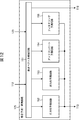
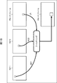
- FIG. 11 is a block diagram showing a main configuration example of the mode determination circuit 123 of FIG.
- mode determination circuit 123 includes intra prediction circuit 141, unidirectional prediction circuit 142, bidirectional prediction circuit 143, upconversion prediction circuit 144, filtering prediction circuit 145, prediction error calculation circuit 146, and determination.
- a circuit 147 is included.
- intra prediction and inter prediction are performed on blocks of different sizes, and from which result it is determined in which prediction mode to perform prediction.
- processing is performed in each prediction mode of unidirectional prediction mode, bidirectional prediction mode, upconversion prediction mode, and filtering prediction mode.
- the intra prediction circuit 141, the unidirectional prediction circuit 142, the bi-directional prediction circuit 143, the upconversion prediction circuit 144, and the filtering prediction circuit 145 are based on the original image and the image read from the frame memory 122 by respective methods. , And generates a prediction image, and outputs the generated prediction image to the prediction error calculation circuit 146.
- the intra prediction circuit 141 performs intra prediction in the same manner as the intra prediction circuit 22 of the decoding device 1.
- the unidirectional prediction circuit 142 detects a motion vector, extracts a motion compensated image from the reference frame based on the detected motion vector, and generates a predicted image by performing unidirectional prediction using the motion compensated image. . That is, the unidirectional prediction circuit 142 generates a predicted image in the same manner as the unidirectional prediction circuit 61 of the decoding device 1 based on the detected motion vector.
- the bidirectional prediction circuit 143 detects a motion vector, extracts a motion compensated image from a reference frame based on the detected motion vector, and generates a predicted image by performing bidirectional prediction using the motion compensated image. . That is, the bidirectional prediction circuit 143 generates a predicted image in the same manner as the bidirectional prediction circuit 62 of the decoding device 1 based on the detected motion vector.
- the upconversion prediction circuit 144 sets a macroblock at the same position as the processing target macroblock of the current frame of the enhancement layer in the current frame of the base layer as a motion compensation image, and upconverts it to obtain a predicted image of the enhancement layer. Generate That is, the upconversion prediction circuit 144 generates a prediction image in the same manner as the upconversion prediction circuit 63 of the decoding device 1.
- the filtering prediction circuit 145 detects a motion vector in the base layer, extracts a motion compensated image of the base layer from the reference frame based on the detected motion vector, and performs filtering prediction using the motion compensated image of the base layer To generate a predicted image. That is, the filtering prediction circuit 145 generates a prediction image in the same manner as the filtering prediction circuit 145 of the decoding device 1 based on the detected motion vector.
- the intra prediction circuit 141 to the filtering prediction circuit 145 detect or predict motion vectors in units of 4 ⁇ 4 pixel blocks, 8 ⁇ 8 pixel blocks, and 16 ⁇ 16 pixel blocks, for example. To The size of the block serving as the processing unit is arbitrary. Also, the number of types of blocks to be predicted is arbitrary. The intra prediction circuit 141 to the filtering prediction circuit 145 generate prediction images for each block, and output the generated prediction images to the prediction error calculation circuit 146.
- the original image supplied from the reordering buffer 112 is input to the intra prediction circuit 141 to the filtering prediction circuit 145 and the prediction error calculation circuit 146.
- the prediction error calculation circuit 146 obtains a difference between the prediction image supplied from each circuit of the intra prediction circuit 141 and the original image, and outputs a residual signal representing the obtained difference to the determination circuit 147. Similarly, the prediction error calculation circuit 146 obtains a difference from the original image for each prediction image supplied from the unidirectional prediction circuit 142, the bidirectional prediction circuit 143, the upconversion prediction circuit 144, or the filtering prediction circuit 145. The residual signal representing the obtained difference is output to the determination circuit 147.
- the determination circuit 147 measures the strength of the residual signal supplied from the prediction error calculation circuit 146, and generates a prediction image to be used for encoding, using the prediction method used to generate a prediction image having a small difference from the original image. As a prediction method to The determination circuit 147 outputs information representing the determination result to the lossless encoding circuit 116 as mode information.
- the mode information also includes information indicating which block size is used as a processing unit.
- the determination circuit 147 determines to generate a prediction image by inter prediction (when it is determined to perform inter coding)
- the reference frame read from the frame memory 122 is subjected to motion prediction / compensation together with mode information. It outputs to the circuit 125.
- the determination circuit 147 determines to generate a predicted image by intra prediction (when it is determined to perform intra coding)
- the image used for intra prediction read from the frame memory 122 is also used as an intra prediction circuit together with mode information. Output to 126.
- FIG. 12 is a block diagram showing an example of the main configuration of the motion prediction / compensation circuit 125 of FIG.
- the motion prediction / compensation circuit 125 includes a motion vector detection circuit 151, a one-way prediction circuit 152, a bidirectional prediction circuit 153, an upconversion prediction circuit 154, and a filtering circuit 155.
- the motion prediction / compensation circuit 125 has the same configuration as the motion prediction / compensation circuit 21 shown in FIG. 5 except that a motion vector detection circuit 151 is provided instead of the prediction selection circuit 51.
- the motion vector detection circuit 151 detects a motion vector by performing block matching or the like based on the original image supplied from the reordering buffer 112 and the reference frame supplied from the mode determination circuit 123.
- the motion vector detection circuit 151 refers to the mode information supplied from the mode determination circuit 123, and outputs the reference frame to any one of the unidirectional prediction circuit 152 to the filtering prediction circuit 155.
- the motion vector detection circuit 151 also outputs the motion vector to the output destination of the reference frame as needed.
- the motion vector detection circuit 151 outputs the motion vector together with the reference frame to the unidirectional prediction circuit 152 when unidirectional prediction is selected, and when bidirectional prediction is selected, both of the information are displayed.
- the signal is output to the direction prediction circuit 153.
- the motion vector detection circuit 151 outputs the image of the current frame of the base layer, which is a reference frame, to the upconversion prediction circuit 154 when the upconversion prediction is selected.
- the motion vector detection circuit 151 outputs the motion vector to the filtering prediction circuit 155 together with the reference frame of the base layer when the filtering prediction is selected.
- the one-way prediction circuit 152 generates a predicted image by performing one-way prediction in the same manner as the one-way prediction circuit 61 of FIG. 5.
- the one-way prediction circuit 152 outputs the generated predicted image to the addition circuit 113.
- the bidirectional prediction circuit 153 generates a predicted image by performing bidirectional prediction.
- the bidirectional prediction circuit 153 outputs the generated predicted image to the addition circuit 113.
- the upconversion prediction circuit 154 Similar to the upconversion prediction circuit 63 of FIG. 5, the upconversion prediction circuit 154 generates a prediction image by performing upconversion prediction.
- the up-conversion prediction circuit 154 outputs the generated predicted image to the addition circuit 113.
- the filtering prediction circuit 155 extracts motion compensated images from the plurality of reference frames of the base layer, and performs filtering prediction with up conversion on the extracted motion compensated images. To generate a predicted image.
- the filtering prediction circuit 155 outputs the generated predicted image to the addition circuit 113.
- the filtering prediction circuit 155 has a configuration similar to that of the filtering prediction circuit 64 shown in FIG.
- the configuration of the filtering prediction circuit 64 shown in FIG. 6 will be referred to and described as the configuration of the filtering prediction circuit 155 as appropriate.
- the predicted image generated by the filtering prediction contains more high frequency components than the predicted image generated by one-way prediction, bi-directional prediction, or up-conversion prediction, and becomes an image with a small difference from the original image. Therefore, the filtering prediction can increase the coding efficiency because the code amount assigned to the residual can be small.
- filtering prediction has a smaller resolution of the reference frame as compared to the case of unidirectional prediction or bidirectional prediction that refers to a frame of the enhancement layer, so, for example, storage of the reference frame in frame memory 122 or frame memory 122
- the processing load such as reading is small. That is, by using filtering prediction, the encoding apparatus 101 can improve the encoding efficiency while suppressing an increase in the load of encoding and decoding.
- the filtering prediction can be performed if the number of reference frames is at least two, it is possible to realize such an increase in coding efficiency without complicating the process.
- the number of reference frames used in inter prediction may be increased to generate a highly accurate predicted image, and using it also makes it possible to reduce the residual from the original image and improve the coding efficiency. In this case, the processing becomes complicated because the number of reference frames increases.
- an optimal prediction method is selected by adding a weight according to the code amount to the strength of the residual signal, taking into consideration the code amount of information such as motion vectors and coding modes required for prediction. You may This makes it possible to further improve the coding efficiency. Further, in order to simplify the encoding process, the prediction method may be adaptively selected by using the time-space feature of the input original image.
- the encoding process for the enhancement layer of the encoding device 101 will be described with reference to the flowchart in FIG. This process is started when an image of a predetermined unit such as a macroblock is output from the reordering buffer 112. Note that the encoding process for the base layer is the same as the method based on the H.264 specification as described above, and thus the description thereof is omitted.
- step S101 the addition circuit 113 obtains a difference between the image supplied from the reordering buffer 112 and the predicted image generated by the motion prediction / compensation circuit 125 or the intra prediction circuit 126, and the residual is orthogonal transform circuit 114. Output to
- step S 102 the orthogonal transformation circuit 114 performs orthogonal transformation on the residual supplied from the addition circuit 113, and outputs transformation coefficients to the quantization circuit 115.
- step S103 the quantization circuit 115 quantizes the transform coefficient supplied from the orthogonal transform circuit 114 and outputs the quantized transform coefficient.
- step S104 the inverse quantization circuit 119 applies inverse quantization to the transform coefficient quantized by the quantization circuit 115, and outputs the transform coefficient to the inverse orthogonal transform circuit 120.
- step S 105 the inverse orthogonal transformation circuit 120 performs inverse orthogonal transformation on the transform coefficient supplied from the inverse quantization circuit 119, and outputs the obtained image to the deblocking filter 121.
- step S106 the deblocking filter 121 removes block distortion by filtering, and outputs the image from which the block distortion has been removed to the frame memory 122.
- step S107 the frame memory 122 stores the image supplied from the deblocking filter 121.
- step S108 the mode determination circuit 123 performs mode determination processing.
- the mode determination process determines in which prediction mode to generate a predicted image. Details of the mode determination process will be described later.
- step S109 the motion prediction / compensation circuit 125 or the intra prediction circuit 126 generates a predicted image in the mode determined in step S108. This predicted image is used in the process of step S101.
- step S 110 the lossless encoding circuit 116 compresses the transform coefficient supplied from the quantization circuit 115 and outputs the result to the accumulation buffer 117. Also, the lossless encoding circuit 116 describes the identification flag in the header of the image according to the information supplied from the mode determination circuit 123, describes the motion vector supplied from the motion prediction / compensation circuit 125 in the header of the image, Do.
- step S111 the accumulation buffer 117 temporarily stores the information supplied from the lossless encoding circuit 116.
- step S112 the control circuit 31 determines whether or not the above processing has been performed for the entire macroblock of one frame, and when it is determined that the processing is not performed, attention is paid to the other macroblocks and step S101. Repeat the subsequent processing.
- step S112 when it is determined in step S112 that the process has been performed on the macroblock of the entire one frame, the storage buffer 117 outputs the compressed image information under the control of the control circuit 131 in step S113.
- the above processing is performed for each frame.
- step S131 the intra prediction circuit 141 to the filtering prediction circuit 145 perform intra prediction and inter prediction on blocks of different sizes, respectively, to generate predicted images.
- the generated predicted image is supplied to the prediction error calculation circuit 146.
- step S132 the prediction error calculation circuit 146 obtains a difference between the prediction image supplied from the intra prediction circuit 141 to the filtering prediction circuit 145 and the original image.
- the prediction error calculation circuit 146 outputs the residual signal to the determination circuit 147.
- step S133 based on the strength of the residual signal supplied from the prediction error calculation circuit 146, the determination circuit 147 determines a prediction method for generating a predicted image to be supplied to the addition circuit 113.
- step S134 the determination circuit 147 outputs mode information, which is information related to the determined prediction method, to the lossless encoding circuit 116. Thereafter, the process returns to step S108 in FIG. 13 and the subsequent processing is performed.
- step S109 of FIG. 13 generation of a prediction image is performed in the mode determined by the mode determination process of step S108. Therefore, when the filtering prediction mode is determined in step S108, the filtering prediction process as shown in FIG. 15 is performed in step S109.
- step S151 the motion vector detection circuit 151 detects a motion vector based on the original image and the reference frame.
- a motion compensated image is generated in the reference frame of the base layer based on the motion vector, and the motion compensated image is subjected to filtering processing with up conversion to generate a predicted image of the enhancement layer.
- step S161 When the process of step S161 is completed, the filtering prediction process is completed, the process returns to step S109 of FIG. 13, and the processes of step S110 and subsequent steps are performed.
- step S108 If another mode is selected in the process of step S108, the motion prediction / compensation circuit 125 or the intra prediction circuit 126 generates a prediction image in the selected other mode. Since these processes are performed according to the H.264 / SVC standard, the description thereof is omitted.
- FIG. 16 is a diagram for explaining another example of the outline of the decoding process to which the present invention is applied. As shown in FIG. 16, the number of reference frames may be three or more.
- a frame one time before the current frame is a reference frame Ref0
- a frame one time before the reference frame Ref0 is a reference frame Ref1
- a frame one time before the reference frame Ref1 is a reference frame Ref2.
- FIG. 17 is a block diagram showing a configuration example of the filtering circuit of FIG. 6 in the case of referring to three frames in this manner.
- the filtering circuit 211 includes a filtering circuit 221 and a filtering circuit 222.
- the filtering circuit 221 and the filtering circuit 222 each have a configuration as shown in FIG. That is, the filtering circuit 211 operates as a circuit with three inputs and one output by cascading the filtering circuits 72 used when two inputs and one output.
- the extraction circuit 71 extracts a motion compensated image from each of the three reference frames (Ref0, Ref1, Ref2). That is, the extraction circuit 71 extracts, for example, the motion compensated image MC0 from the reference frame Ref0. Also, for example, the extraction circuit 71 extracts the motion compensated image MC1 from the reference frame Ref1. Furthermore, for example, the extraction circuit 71 extracts the motion compensated image MC2 from the reference frame Ref2.
- the motion compensated images MC1 and MC2 are input to the filtering circuit 221, and the motion compensated image MC0 is input to the filtering circuit 222.
- the filtering circuit 221 filters the motion compensated images MC1 and MC2 as the motion compensated images MC0 and MC1 in FIG. 6 and the like, and outputs an intermediate output X as a result of the filtering to the filtering circuit 222.
- the filtering circuit 221 filters the intermediate output X and the motion compensated image MC0 as motion compensated images MC0 and MC1 in FIG. 6 and the like, and outputs the result of the filtering as a predicted image.
- the filtering circuit 221 and the filtering circuit 222 do not have to have the same configuration, and may have different configurations. It is also possible to make the parameters (for example, ⁇ , ⁇ ) used for the filter different in consideration of input / output characteristics before and after filtering.
- the filtering circuit 211 applies filtering to a motion compensated image extracted from three reference frames preceding and succeeding, not a motion compensated image extracted from a reference frame located temporally on one side. Good.
- parameters such as tap coefficients at the time of filtering may be dynamically changed according to the time direction and distance of the reference frame.
- Transmission of compressed image information from the encoding device 101 to the decoding device 1 is performed via various media such as an optical disk, a magnetic disk, a recording medium such as a flash memory, satellite broadcasting, cable TV, the Internet, and a cellular phone network.
- various media such as an optical disk, a magnetic disk, a recording medium such as a flash memory, satellite broadcasting, cable TV, the Internet, and a cellular phone network.
- the motion compensated image is described as being extracted from the reference frame of the base layer, but the motion compensated image is extracted from any layer other than the base layer It may be done.
- the compressed image information forms a three-layer structure consisting of the first to third layers, the first layer being the base layer and the lowest resolution layer, and the second layer being the next lowest resolution layer.
- the third layer is the highest resolution layer.
- a motion compensated image may be extracted from the reference frame of the second layer other than the base layer.
- the motion compensated image may be extracted from the reference frame of the first layer which is the base layer.
- a motion compensated image may be extracted from a reference frame of the same layer as the predicted image to be generated.
- a low resolution motion compensated image may be extracted from the reference frame of the third layer in the filtering prediction of the third layer.
- FIG. 18 is a diagram for explaining an outline of the decoding process in this case.
- the reference frame Ref0 and the reference frame Ref1 are frames of the same enhancement layer as the predicted image.
- the resolution of the motion compensated image extracted from each reference frame is lower than that of the predicted image.
- the position (range) corresponding to the processing target macroblock is specified by the motion vector, and the pixel values within that range are It is drawn and extracted as a motion compensated image.
- the position corresponding to the processing target macroblock is identified by the motion vector, and the processing target macroblock centered on that position A range smaller than the size of is extracted as a motion compensated image.
- other methods may be used.
- the motion-compensated image to be extracted may have a lower resolution than the predicted image, the extraction method is arbitrary, and the motion-compensated image may be extracted from any layer.
- the low-resolution motion-compensated image extracted in this manner is subjected to filtering processing including up-conversion as in the other cases described above to generate a predicted image of a desired resolution.
- the configuration of the encoding apparatus 1 in this case is basically the same as the configuration described with reference to FIGS. 3 to 6, since only the layer for generating the motion compensated image is different.
- the frame memory 19 holds the frame of the enhancement layer, and the extraction circuit 71 reads the image of the enhancement layer from the frame memory 19.
- the extraction circuit 71 extracts a motion compensated image at low resolution from the reference frame of the enhancement layer in step S341.
- the processes of step S342 to step S350 are performed in the same manner as the processes of step S42 to step S50 of FIG. 9, and a prediction image is generated as in the case of FIG.
- step S350 ends, the filtering prediction process ends, and the process returns to step S28 in FIG. 8 and proceeds to step S29.
- the decoding device 1 more efficiently uses the temporal correlation included in the moving image signal sequence to obtain a predicted image with high resolution and high accuracy. Can be generated, and the coding efficiency can be improved. Further, since the motion compensated image can be made to have a lower resolution than the predicted image, the decoding device 1 can reduce, for example, the amount of image information read out from the frame memory, increasing the load of processing such as encoding and decoding. Coding efficiency can be improved while suppressing.
- the configuration of the encoding device 101 corresponding to the decoding device 1 in this case is basically the same as that described with reference to FIGS. 10 to 12.
- the frame memory 122 holds the frame of the enhancement layer
- the mode determination processing 123 reads the image of the enhancement layer from the frame memory 19.
- the configurations of the filtering prediction circuit 145 of the mode determination processing 123 and the filtering prediction circuit 155 of the motion prediction / compensation circuit 125 are the filtering prediction circuit shown in FIG. 6 as in FIGS. It is similar to the 64 configuration. However, as in the case of the decoding device 1, the extraction circuit 71 extracts a motion compensated image from the frame of the enhancement layer.
- the motion vector detection circuit 151 detects a motion vector in step S451, as in the case of step S151 in FIG.
- the extraction circuit 71 extracts a motion compensated image at low resolution from the reference frame of the enhancement layer.
- the processes of steps S453 to S461 are performed in the same manner as the processes of steps S153 to S161 of FIG. 15, and a prediction image is generated as in the case of FIG.
- step S461 ends, the filtering prediction process ends, and the process returns to step S109 of FIG. 13 and proceeds to step S110.
- the encoding device 101 performs prediction of high resolution with high accuracy by more efficiently using temporal correlation included in a moving image signal sequence. Images can be generated and coding efficiency can be improved.
- the encoding device 101 can reduce, for example, the amount of image information read from the frame memory, and the load of processing such as encoding and decoding increases. The coding efficiency can be improved while suppressing the
- this method can also be applied to the case of encoding / decoding image information with a single layer structure in which spatial scalability is not considered. That is, the present invention can also be applied to encoding / decoding of the H.264 / AVC standard.
- the motion compensated image may be extracted in a plurality of layers.
- the filtering prediction processing since the difference of the motion compensated images is obtained, it is necessary to make the resolutions of the respective motion compensated images coincide with each other by that time.
- a central processing unit (CPU) 501 of the personal computer 500 executes various programs according to a program stored in a read only memory (ROM) 502 or a program loaded from a storage unit 513 to a random access memory (RAM) 503. Execute the process of The RAM 503 also appropriately stores data and the like necessary for the CPU 501 to execute various processes.
- ROM read only memory
- RAM random access memory
- the CPU 501, the ROM 502, and the RAM 503 are connected to one another via a bus 504.
- An input / output interface 510 is also connected to the bus 504.
- the input / output interface 510 includes an input unit 511 such as a keyboard and a mouse, a display such as a CRT (Cathode Ray Tube) or an LCD (Liquid Crystal Display), an output unit 512 such as a speaker, and a hard disk.
- a communication unit 514 including a storage unit 513 and a modem is connected. The communication unit 514 performs communication processing via a network including the Internet.
- a drive 515 is also connected to the input / output interface 510 as necessary, and removable media 521 such as a magnetic disk, an optical disk, a magneto-optical disk, or a semiconductor memory are appropriately attached, and a computer program read from them is It is installed in the storage unit 513 as necessary.
- a program that configures the software is installed from a network or a recording medium.
- this recording medium is a magnetic disk (including a flexible disk) on which a program is recorded, which is distributed for distributing the program to the user separately from the apparatus main body, an optical disk ( It consists only of removable media 521 consisting of CD-ROM (Compact Disc-Read Only Memory), DVD (Digital Versatile Disc), Magneto-Optical Disc (including MD (Mini Disc), or semiconductor memory etc. Instead, it is composed of the ROM 502 in which the program is recorded, which is distributed to the user in a state of being incorporated in the apparatus main body, a hard disk included in the storage unit 513, and the like.
- the program executed by the computer may be a program that performs processing in chronological order according to the order described in this specification, in parallel, or when necessary, such as when a call is made. It may be a program to be processed.
- the step of describing the program to be recorded on the recording medium is not limited to processing performed chronologically in the order described, but not necessarily parallel processing It also includes processing to be executed individually.
- system represents the entire apparatus configured by a plurality of devices (apparatus).
- the configuration described above as one device (or processing unit) may be divided and configured as a plurality of devices (or processing units).
- the configuration described as a plurality of devices (or processing units) in the above may be collectively configured as one device (or processing unit).
- configurations other than those described above may be added to the configuration of each device (or each processing unit).
- part of the configuration of one device (or processing unit) may be included in the configuration of another device (or other processing unit) if the configuration or operation of the entire system is substantially the same. . That is, the embodiment of the present invention is not limited to the above-described embodiment, and various modifications can be made without departing from the scope of the present invention.
- the decoding device 1 and the encoding device 101 described above can be applied to any electronic device.
- the example will be described below.
- FIG. 22 is a block diagram showing a main configuration example of a television receiver using the decoding device 1 to which the present invention is applied.
- the television receiver 1000 shown in FIG. 22 includes a terrestrial tuner 1013, a video decoder 1015, a video signal processing circuit 1018, a graphic generation circuit 1019, a panel drive circuit 1020, and a display panel 1021.
- the terrestrial tuner 1013 receives a broadcast wave signal of terrestrial analog broadcasting via an antenna, demodulates it, acquires a video signal, and supplies it to a video decoder 1015.
- the video decoder 1015 performs decoding processing on the video signal supplied from the terrestrial tuner 1013, and supplies the obtained digital component signal to the video signal processing circuit 1018.
- the video signal processing circuit 1018 performs predetermined processing such as noise removal on the video data supplied from the video decoder 1015, and supplies the obtained video data to the graphic generation circuit 1019.
- the graphic generation circuit 1019 generates video data of a program to be displayed on the display panel 1021, image data by processing based on an application supplied via a network, and the like, and transmits the generated video data and image data to the panel drive circuit 1020. Supply. Also, the graphic generation circuit 1019 generates video data (graphic) for displaying a screen used by the user for item selection and the like, and a video obtained by superimposing it on video data of a program. A process of supplying data to the panel drive circuit 1020 is also performed as appropriate.
- the panel drive circuit 1020 drives the display panel 1021 based on the data supplied from the graphic generation circuit 1019 and causes the display panel 1021 to display the video of the program and the various screens described above.
- the display panel 1021 is formed of an LCD (Liquid Crystal Display) or the like, and displays an image or the like of a program according to control of the panel drive circuit 1020.
- LCD Liquid Crystal Display
- the television receiver 1000 also includes an audio A / D (Analog / Digital) conversion circuit 1014, an audio signal processing circuit 1022, an echo cancellation / audio synthesis circuit 1023, an audio amplification circuit 1024, and a speaker 1025.
- an audio A / D (Analog / Digital) conversion circuit 1014 An audio signal processing circuit 1022, an echo cancellation / audio synthesis circuit 1023, an audio amplification circuit 1024, and a speaker 1025.
- the terrestrial tuner 1013 acquires not only a video signal but also an audio signal by demodulating the received broadcast wave signal.
- the terrestrial tuner 1013 supplies the acquired audio signal to the audio A / D conversion circuit 1014.
- the audio A / D conversion circuit 1014 performs A / D conversion processing on the audio signal supplied from the terrestrial tuner 1013, and supplies the obtained digital audio signal to the audio signal processing circuit 1022.
- the audio signal processing circuit 1022 performs predetermined processing such as noise removal on the audio data supplied from the audio A / D conversion circuit 1014, and supplies the obtained audio data to the echo cancellation / audio synthesis circuit 1023.
- the echo cancellation / voice synthesis circuit 1023 supplies the voice data supplied from the voice signal processing circuit 1022 to the voice amplification circuit 1024.
- the voice amplification circuit 1024 subjects the voice data supplied from the echo cancellation / voice synthesis circuit 1023 to D / A conversion processing and amplification processing, adjusts the volume to a predetermined level, and outputs voice from the speaker 1025.
- the television receiver 1000 also includes a digital tuner 1016 and an MPEG decoder 1017.
- a digital tuner 1016 receives a broadcast wave signal of digital broadcast (terrestrial digital broadcast, BS (Broadcasting Satellite) / CS (Communications Satellite) digital broadcast) via an antenna, and demodulates the signal, and generates an MPEG-TS (Moving Picture Experts Group). -Transport Stream) and supply it to the MPEG decoder 1017.
- digital broadcast terrestrial digital broadcast, BS (Broadcasting Satellite) / CS (Communications Satellite) digital broadcast
- MPEG-TS Motion Picture Experts Group
- the MPEG decoder 1017 unscrambles the MPEG-TS supplied from the digital tuner 1016, and extracts a stream including data of a program to be reproduced (targeted to be viewed).
- the MPEG decoder 1017 decodes the audio packet forming the extracted stream, supplies the obtained audio data to the audio signal processing circuit 1022, decodes the video packet forming the stream, and outputs the obtained video data as an image.
- the signal processing circuit 1018 is supplied.
- the MPEG decoder 1017 supplies EPG (Electronic Program Guide) data extracted from the MPEG-TS to the CPU 1032 via a path (not shown).
- EPG Electronic Program Guide
- the television receiver 1000 uses the above-described decoding device 1 as the MPEG decoder 1017 that decodes video packets in this manner.
- the MPEG-TS transmitted from a broadcast station or the like is encoded by the encoding device 101.
- the MPEG decoder 1017 performs filtering on images of a plurality of reference planes in the base layer to generate a predicted image of the current block in the enhancement layer. Therefore, the MPEG decoder 1017 can use signal components in the image sequence more effectively than spatial up-sampling filters. As a result, the prediction image can reduce the prediction residual while having spatially higher frequency components than the prediction image generated by the conventional up-conversion prediction using the image of the current frame of the base layer. That is, the code amount of the coded picture in the enhancement layer can be reduced, which can contribute to the improvement of the coding efficiency.
- the processing amount required for encoding, the temporary storage capacity, the amount of information read from memory, etc. can be reduced. Costs can be reduced. In addition, power consumption can be reduced.
- the video data supplied from the MPEG decoder 1017 is subjected to predetermined processing in the video signal processing circuit 1018 as in the case of the video data supplied from the video decoder 1015, and the video data generated in the graphic generation circuit 1019. Etc. are appropriately superimposed and supplied to the display panel 1021 via the panel drive circuit 1020, and the image is displayed.
- the audio data supplied from the MPEG decoder 1017 is subjected to predetermined processing in the audio signal processing circuit 1022 as in the case of the audio data supplied from the audio A / D conversion circuit 1014, and the echo cancellation / audio synthesis circuit 1023.
- the audio amplification circuit 1024 are supplied to the audio amplification circuit 1024 and subjected to D / A conversion processing and amplification processing.
- the sound adjusted to a predetermined volume is output from the speaker 1025.
- the television receiver 1000 also includes a microphone 1026 and an A / D conversion circuit 1027.
- the A / D conversion circuit 1027 receives the user's voice signal captured by the microphone 1026 provided in the television receiver 1000 for voice conversation, and performs A / D conversion processing on the received voice signal.
- the obtained digital voice data is supplied to an echo cancellation / voice synthesis circuit 1023.
- the echo cancellation / voice synthesis circuit 1023 performs echo cancellation on the voice data of the user A when the voice data of the user (user A) of the television receiver 1000 is supplied from the A / D conversion circuit 1027.
- the voice data obtained by synthesizing with other voice data is output from the speaker 1025 via the voice amplification circuit 1024.
- the television receiver 1000 further includes an audio codec 1028, an internal bus 1029, a synchronous dynamic random access memory (SDRAM) 1030, a flash memory 1031, a CPU 1032, a universal serial bus (USB) I / F 1033, and a network I / F 1034.
- SDRAM synchronous dynamic random access memory
- USB universal serial bus
- the A / D conversion circuit 1027 receives the user's voice signal captured by the microphone 1026 provided in the television receiver 1000 for voice conversation, and performs A / D conversion processing on the received voice signal.
- the obtained digital audio data is supplied to an audio codec 1028.
- the voice codec 1028 converts voice data supplied from the A / D conversion circuit 1027 into data of a predetermined format for transmission via the network, and supplies the data to the network I / F 1034 via the internal bus 1029.
- the network I / F 1034 is connected to the network via a cable attached to the network terminal 1035.
- the network I / F 1034 transmits voice data supplied from the voice codec 1028 to, for example, another device connected to the network.
- the network I / F 1034 receives, for example, voice data transmitted from another device connected via the network via the network terminal 1035, and transmits it to the voice codec 1028 via the internal bus 1029. Supply.
- the voice codec 1028 converts voice data supplied from the network I / F 1034 into data of a predetermined format, and supplies it to the echo cancellation / voice synthesis circuit 1023.
- the echo cancellation / voice synthesis circuit 1023 performs echo cancellation on voice data supplied from the voice codec 1028, and combines voice data obtained by combining with other voice data, etc., via the voice amplification circuit 1024. And output from the speaker 1025.
- the SDRAM 1030 stores various data necessary for the CPU 1032 to perform processing.
- the flash memory 1031 stores a program executed by the CPU 1032.
- the program stored in the flash memory 1031 is read by the CPU 1032 at a predetermined timing such as when the television receiver 1000 starts up.
- the flash memory 1031 also stores EPG data acquired via digital broadcasting, data acquired from a predetermined server via a network, and the like.
- the flash memory 1031 stores an MPEG-TS including content data acquired from a predetermined server via the network under the control of the CPU 1032.
- the flash memory 1031 supplies the MPEG-TS to the MPEG decoder 1017 via the internal bus 1029 under the control of the CPU 1032, for example.
- the MPEG decoder 1017 processes the MPEG-TS in the same manner as the MPEG-TS supplied from the digital tuner 1016. As described above, the television receiver 1000 receives content data including video and audio via the network, decodes the content data using the MPEG decoder 1017, displays the video, and outputs audio. Can.
- the television receiver 1000 also includes a light receiving unit 1037 that receives an infrared signal transmitted from the remote controller 1051.
- the light receiving unit 1037 receives the infrared light from the remote controller 1051, and outputs a control code representing the content of the user operation obtained by demodulation to the CPU 1032.
- the CPU 1032 executes a program stored in the flash memory 1031 and controls the overall operation of the television receiver 1000 according to a control code or the like supplied from the light receiving unit 1037.
- the CPU 1032 and each part of the television receiver 1000 are connected via a path (not shown).
- the USB I / F 1033 transmits / receives data to / from an external device of the television receiver 1000 connected via a USB cable attached to the USB terminal 1036.
- the network I / F 1034 is connected to the network via a cable attached to the network terminal 1035, and transmits / receives data other than voice data to / from various devices connected to the network.
- the television receiver 1000 can obtain a high-definition decoded image without increasing the load in decoding of video packets constituting a stream. That is, the television receiver 1000 can improve the coding efficiency while suppressing an increase in load.
- FIG. 23 is a block diagram showing a main configuration example of a mobile phone using the decoding device 1 and the encoding device 101 to which the present invention is applied.
- a mobile phone 1100 shown in FIG. 23 is configured to control each part in an integrated manner, and includes a main control unit 1150, a power supply circuit unit 1151, an operation input control unit 1152, an image encoder 1153, a camera I / F unit 1154 and an LCD control. It has a unit 1155, an image decoder 1156, a demultiplexing unit 1157, a recording / reproducing unit 1162, a modulation / demodulation circuit unit 1158, and an audio codec 1159. These are connected to one another via a bus 1160.
- the cellular phone 1100 further includes an operation key 1119, a CCD (Charge Coupled Devices) camera 1116, a liquid crystal display 1118, a storage portion 1123, a transmitting / receiving circuit portion 1163, an antenna 1114, a microphone (microphone) 1121, and a speaker 1117.
- CCD Charge Coupled Devices
- the power supply circuit unit 1151 starts the cellular phone 1100 in an operable state by supplying power from the battery pack to each unit.
- the cellular phone 1100 transmits and receives audio signals, transmits and receives e-mails and image data, and images in various modes such as a voice call mode and a data communication mode based on the control of the main control unit 1150 including CPU, ROM and RAM. Perform various operations such as shooting or data recording.
- the portable telephone 1100 converts an audio signal collected by the microphone (microphone) 1121 into digital audio data by the audio codec 1159, spread spectrum processes it by the modulation / demodulation circuit unit 1158, and transmits / receives A section 1163 performs digital-to-analog conversion processing and frequency conversion processing.
- the cellular phone 1100 transmits the transmission signal obtained by the conversion process to a base station (not shown) via the antenna 1114.
- the transmission signal (voice signal) transmitted to the base station is supplied to the mobile phone of the other party via the public telephone network.
- the cellular phone 1100 amplifies the reception signal received by the antenna 1114 by the transmission / reception circuit unit 1163, further performs frequency conversion processing and analog-to-digital conversion processing, and the spectrum despreading processing by the modulation / demodulation circuit unit 1158. And converted into an analog voice signal by the voice codec 1159.
- the cellular phone 1100 outputs the analog audio signal obtained by the conversion from the speaker 1117.
- the cellular phone 1100 receives text data of the e-mail input by the operation of the operation key 1119 in the operation input control unit 1152.
- the portable telephone 1100 processes the text data in the main control unit 1150, and causes the liquid crystal display 1118 to display the text data as an image through the LCD control unit 1155.
- the mobile phone 1100 causes the main control unit 1150 to generate e-mail data based on the text data accepted by the operation input control unit 1152 and the user's instruction.
- the portable telephone 1100 performs spread spectrum processing on the electronic mail data in the modulation / demodulation circuit unit 1158, and performs digital / analog conversion processing and frequency conversion processing in the transmission / reception circuit unit 1163.
- the cellular phone 1100 transmits the transmission signal obtained by the conversion process to a base station (not shown) via the antenna 1114.
- the transmission signal (e-mail) transmitted to the base station is supplied to a predetermined destination via a network, a mail server, and the like.
- the cellular phone 1100 receives a signal transmitted from the base station via the antenna 1114 by the transmission / reception circuit unit 1163, amplifies it, and further performs frequency conversion processing and Perform analog-to-digital conversion processing.
- the cellular phone 1100 despreads the received signal by the modulation / demodulation circuit unit 1158 to restore the original electronic mail data.
- the portable telephone 1100 displays the restored electronic mail data on the liquid crystal display 1118 via the LCD control unit 1155.
- the portable telephone 1100 can also record (store) the received electronic mail data in the storage unit 1123 via the recording / reproducing unit 1162.
- the storage unit 1123 is an arbitrary rewritable storage medium.
- the storage unit 1123 may be, for example, a semiconductor memory such as a RAM or a built-in flash memory, or may be a hard disk, or a removable disk such as a magnetic disk, a magneto-optical disk, an optical disk, a USB memory, or a memory card It may be media. Of course, it may be something other than these.
- the cellular phone 1100 when transmitting image data in the data communication mode, the cellular phone 1100 generates image data with the CCD camera 1116 by imaging.
- the CCD camera 1116 has an optical device such as a lens or an aperture and a CCD as a photoelectric conversion element, picks up an object, converts the intensity of received light into an electrical signal, and generates image data of the image of the object.
- the CCD camera 1116 encodes the image data with the image encoder 1153 via the camera I / F unit 1154 and converts it into encoded image data.
- the cellular phone 1100 uses the above-described encoding device 101 as the image encoder 1153 that performs such processing.
- the image encoder 1153 uses filtering prediction to generate a predicted image. By doing this, it is possible to obtain a predicted image which contains a large number of high frequency components as compared with a predicted image generated by one-way prediction, bidirectional prediction, or up-conversion prediction, and which has a small difference from the original image. Therefore, the amount of code to be assigned to the residual can be small, and the coding efficiency can be increased.
- the resolution of the reference frame is smaller than in the case of unidirectional prediction or bidirectional prediction that refers to a frame of the enhancement layer, processing load, such as storing the reference frame in the frame memory 122 or reading from the frame memory 122 Is small. Furthermore, since the filtering prediction can be performed if the number of reference frames is at least two, it is possible to realize such an increase in coding efficiency without complicating the process.
- the portable telephone 1100 analog-digital converts the voice collected by the microphone (microphone) 1121 during imaging by the CCD camera 1116 in the audio codec 1159, and further encodes it.
- the cellular phone 1100 multiplexes the encoded image data supplied from the image encoder 1153 and the digital audio data supplied from the audio codec 1159 according to a predetermined scheme in the demultiplexer 1157.
- the cellular phone 1100 performs spread spectrum processing on the multiplexed data obtained as a result by the modulation / demodulation circuit unit 1158, and performs digital / analog conversion processing and frequency conversion processing by the transmission / reception circuit unit 1163.
- the cellular phone 1100 transmits the transmission signal obtained by the conversion process to a base station (not shown) via the antenna 1114.
- the transmission signal (image data) transmitted to the base station is supplied to the other party of communication via a network or the like.
- the cellular phone 1100 can also display the image data generated by the CCD camera 1116 on the liquid crystal display 1118 via the LCD control unit 1155 without passing through the image encoder 1153.
- the cellular phone 1100 transmits the signal transmitted from the base station to the transmitting / receiving circuit portion 1163 via the antenna 1114. Receive, amplify, and perform frequency conversion and analog-to-digital conversion. The cellular phone 1100 despreads the received signal by the modulation / demodulation circuit unit 1158 to restore the original multiplexed data. The portable telephone 1100 separates the multiplexed data in the multiplex separation unit 1157 and divides it into encoded image data and audio data.
- the cellular phone 1100 generates reproduction moving image data by decoding the encoded image data in the image decoder 1156, and causes the liquid crystal display 1118 to display this via the LCD control unit 1155. Thereby, for example, moving image data included in a moving image file linked to the simplified home page is displayed on the liquid crystal display 1118.
- the cellular phone 1100 uses the above-described decoding device 1 as the image decoder 1156 that performs such processing. That is, as in the case of the decoding device 1, the image decoder 1156 performs filtering on images of a plurality of reference planes in the base layer to generate a predicted image of the current block in the enhancement layer. Therefore, the image decoder 1156 can use signal components in the image sequence more effectively than spatial up-sampling filters. As a result, the prediction image can reduce the prediction residual while having spatially higher frequency components than the prediction image generated by the conventional up-conversion prediction using the image of the current frame of the base layer. That is, the code amount of the coded picture in the enhancement layer can be reduced, which can contribute to the improvement of the coding efficiency.
- the processing amount required for encoding, the temporary storage capacity, the amount of information read from memory, etc. can be reduced. Costs can be reduced. In addition, power consumption can be reduced.
- the portable telephone 1100 simultaneously converts digital audio data into an analog audio signal in the audio codec 1159 and causes the speaker 1117 to output the analog audio signal.
- audio data included in a moving image file linked to the simple homepage is reproduced.
- the cellular phone 1100 can also record (store) the data linked to the received simple home page or the like in the storage unit 1123 via the recording / reproducing unit 1162. .
- the main control unit 1150 can analyze the two-dimensional code obtained by the CCD camera 1116 by the main control unit 1150 and obtain the information recorded in the two-dimensional code.
- the cellular phone 1100 can communicate with an external device by infrared light through the infrared communication unit 1181.
- the mobile phone 1100 uses the encoding device 101 as the image encoder 1153 to encode a video in consideration of spatial scalability when encoding and transmitting, for example, image data generated by the CCD camera 1116.
- the encoding device 101 uses the encoding device 101 as the image encoder 1153 to encode a video in consideration of spatial scalability when encoding and transmitting, for example, image data generated by the CCD camera 1116.
- the mobile phone 1100 loads processing when decoding data (encoded data) of a moving image file linked to a simple homepage or the like. It is possible to obtain a high definition decoded image without increasing it. That is, the mobile phone 1100 can improve the coding efficiency while suppressing an increase in load.
- CMOS image sensor CMOS image sensor
- CMOS complementary metal oxide semiconductor
- the mobile phone 1100 has been described above, for example, a PDA (Personal Digital Assistants), a smart phone, a UMPC (Ultra Mobile Personal Computer), a netbook, a notebook personal computer, etc.
- the decoding device 1 and the encoding device 101 can be applied to any device as in the case of the mobile telephone 1100.
- FIG. 24 is a block diagram showing a main configuration example of a hard disk recorder using the decoding device 1 and the encoding device 101 to which the present invention is applied.
- a hard disk recorder (HDD recorder) 1200 shown in FIG. 24 receives audio data and video data of a broadcast program included in a broadcast wave signal (television signal) transmitted by a satellite, a ground antenna, etc., received by a tuner. And an apparatus for storing the stored data in a built-in hard disk and providing the stored data to the user at a timing according to the user's instruction.
- a broadcast wave signal television signal
- the hard disk recorder 1200 can extract, for example, audio data and video data from the broadcast wave signal, decode them appropriately, and store them in a built-in hard disk.
- the hard disk recorder 1200 can also acquire audio data and video data from another device via a network, decode these as appropriate, and store them in a built-in hard disk, for example.
- the hard disk recorder 1200 decodes, for example, audio data or video data recorded in the built-in hard disk and supplies it to the monitor 1260 to display the image on the screen of the monitor 1260. Can be output. Also, the hard disk recorder 1200 decodes, for example, audio data and video data extracted from a broadcast wave signal acquired via a tuner, or audio data and video data acquired from another device via a network. The image can be supplied to the monitor 1260 and the image can be displayed on the screen of the monitor 1260 and the sound can be output from the speaker of the monitor 1260.
- the hard disk recorder 1200 has a receiving unit 1221, a demodulating unit 1222, a demultiplexer 1223, an audio decoder 1224, a video decoder 1225, and a recorder control unit 1226.
- the hard disk recorder 1200 further includes an EPG data memory 1227, a program memory 1228, a work memory 1229, a display converter 1230, an on screen display (OSD) control unit 1231, a display control unit 1232, a recording and reproducing unit 1233, a D / A converter 1234, And a communication unit 1235.
- EPG data memory 1227 a program memory 1228, a work memory 1229, a display converter 1230, an on screen display (OSD) control unit 1231, a display control unit 1232, a recording and reproducing unit 1233, a D / A converter 1234, And a communication unit 1235.
- OSD on screen display
- the display converter 1230 also includes a video encoder 1241.
- the recording / reproducing unit 1233 has an encoder 1251 and a decoder 1252.
- the receiving unit 1221 receives an infrared signal from a remote controller (not shown), converts the signal into an electrical signal, and outputs the signal to the recorder control unit 1226.
- the recorder control unit 1226 is, for example, a microprocessor or the like, and executes various processes in accordance with a program stored in the program memory 1228. At this time, the recorder control unit 1226 uses the work memory 1229 as necessary.
- the communication unit 1235 is connected to a network and performs communication processing with another device via the network.
- the communication unit 1235 is controlled by the recorder control unit 1226, communicates with a tuner (not shown), and mainly outputs a channel selection control signal to the tuner.
- the demodulation unit 1222 demodulates the signal supplied from the tuner and outputs the signal to the demultiplexer 1223.
- the demultiplexer 1223 separates the data supplied from the demodulation unit 1222 into audio data, video data, and EPG data, and outputs the data to the audio decoder 1224, the video decoder 1225, or the recorder control unit 1226, respectively.
- the audio decoder 1224 decodes the input audio data and outputs the decoded audio data to the recording / reproducing unit 1233.
- the video decoder 1225 decodes the input video data and outputs the decoded video data to the display converter 1230.
- the recorder control unit 1226 supplies the input EPG data to the EPG data memory 1227 for storage.
- the display converter 1230 encodes the video data supplied from the video decoder 1225 or the recorder control unit 1226 into video data of, for example, a National Television Standards Committee (NTSC) system by the video encoder 1241 and outputs the video data to the recording / reproducing unit 1233.
- the display converter 1230 converts the screen size of the video data supplied from the video decoder 1225 or the recorder control unit 1226 into a size corresponding to the size of the monitor 1260 and converts the video data into NTSC video data by the video encoder 1241. , And converts it into an analog signal, and outputs it to the display control unit 1232.
- the display control unit 1232 superimposes the OSD signal output from the OSD (On Screen Display) control unit 1231 on the video signal input from the display converter 1230 under the control of the recorder control unit 1226, and displays it on the display of the monitor 1260. Output and display.
- OSD On Screen Display
- the audio data output from the audio decoder 1224 is also converted to an analog signal by the D / A converter 1234 and supplied to the monitor 1260.
- the monitor 1260 outputs this audio signal from the built-in speaker.
- the recording / reproducing unit 1233 has a hard disk as a storage medium for recording video data, audio data and the like.
- the recording / reproducing unit 1233 encodes, for example, the audio data supplied from the audio decoder 1224 by the encoder 1251. Also, the recording / reproducing unit 1233 encodes the video data supplied from the video encoder 1241 of the display converter 1230 by the encoder 1251. The recording / reproducing unit 1233 combines the encoded data of the audio data and the encoded data of the video data by the multiplexer. The recording / reproducing unit 1233 channel-codes and amplifies the synthesized data, and writes the data to the hard disk via the recording head.
- the recording and reproducing unit 1233 reproduces and amplifies the data recorded on the hard disk via the reproducing head, and separates the data into audio data and video data by the demultiplexer.
- the recording / reproducing unit 1233 decodes the audio data and the video data by the decoder 1252.
- the recording / reproducing unit 1233 D / A converts the decoded audio data, and outputs the converted data to a speaker of the monitor 1260. Also, the recording / reproducing unit 1233 D / A converts the decoded video data, and outputs it to the display of the monitor 1260.
- the recorder control unit 1226 reads the latest EPG data from the EPG data memory 1227 based on the user instruction indicated by the infrared signal from the remote controller received via the reception unit 1221, and supplies it to the OSD control unit 1231. Do.
- the OSD control unit 1231 generates image data corresponding to the input EPG data, and outputs the image data to the display control unit 1232.
- the display control unit 1232 outputs the video data input from the OSD control unit 1231 to the display of the monitor 1260 for display. As a result, an EPG (Electronic Program Guide) is displayed on the display of the monitor 1260.
- EPG Electronic Program Guide
- the hard disk recorder 1200 can also acquire various data such as video data, audio data, or EPG data supplied from another device via a network such as the Internet.
- the communication unit 1235 is controlled by the recorder control unit 1226, acquires encoded data such as video data, audio data, and EPG data transmitted from another device via the network, and supplies the encoded data to the recorder control unit 1226. Do.
- the recorder control unit 1226 supplies, for example, encoded data of the acquired video data and audio data to the recording and reproduction unit 1233 and causes the hard disk to store the data. At this time, the recorder control unit 1226 and the recording / reproducing unit 1233 may perform processing such as re-encoding as needed.
- the recorder control unit 1226 decodes encoded data of the acquired video data and audio data, and supplies the obtained video data to the display converter 1230.
- the display converter 1230 processes the video data supplied from the recorder control unit 1226 as well as the video data supplied from the video decoder 1225, supplies it to the monitor 1260 via the display control unit 1232 and displays the image. .
- the recorder control unit 1226 may supply the decoded audio data to the monitor 1260 via the D / A converter 1234 and output the sound from the speaker.
- the recorder control unit 1226 decodes the acquired encoded data of the EPG data, and supplies the decoded EPG data to the EPG data memory 1227.
- the hard disk recorder 1200 as described above uses the decoding device 1 as a decoder incorporated in the video decoder 1225, the decoder 1252, and the recorder control unit 1226. That is, as in the case of the decoding device 1, the video decoder 1225, the decoder 1252, and the decoder incorporated in the recorder control unit 1226 perform filtering on images of a plurality of reference planes in the base layer to obtain an enhancement layer. Generate a predicted image of the current block in.
- the video decoder 1225, the decoder 1252, and the decoder incorporated in the recorder control unit 1226 can use signal components in the image sequence more effectively than spatial up-sampling filters.
- the prediction image can reduce the prediction residual while having spatially higher frequency components than the prediction image generated by the conventional up-conversion prediction using the image of the current frame of the base layer. That is, the code amount of the coded picture in the enhancement layer can be reduced, which can contribute to the improvement of the coding efficiency.
- the processing amount required for encoding, the temporary storage capacity, the amount of information read from memory, etc. can be reduced. Costs can be reduced. In addition, power consumption can be reduced.
- the hard disk recorder 1200 can, for example, decode the video data (coded data) by the tuner or the communication unit 1235 or decode the video data (coded data) by the recording / reproducing unit 1233 from the hard disk, for example. It is possible to obtain a high-definition decoded image without increasing the processing load. That is, the hard disk recorder 1200 can improve the coding efficiency while suppressing an increase in load.
- the hard disk recorder 1200 uses the encoding device 101 as the encoder 1251. Therefore, as in the case of the encoding device 101, the encoder 1251 includes a large number of high-frequency components as compared to the predicted image generated by bi-directional prediction or up-conversion prediction, and obtains a predicted image with a small difference from the original image. Be Therefore, the amount of code to be assigned to the residual can be small, and the coding efficiency can be increased. Since the resolution of the reference frame is smaller than in the case of unidirectional prediction or bidirectional prediction that refers to a frame of the enhancement layer, processing load, such as storing the reference frame in the frame memory 122 or reading from the frame memory 122 Is small. Furthermore, since the filtering prediction can be performed if the number of reference frames is at least two, it is possible to realize such an increase in coding efficiency without complicating the process.
- the hard disk recorder 1200 more efficiently uses the temporal correlation included in the moving image signal sequence, for example, in encoding in consideration of spatial scalability when recording encoded data on the hard disk. For example, coding efficiency can be improved while suppressing an increase in processing load such as coding and decoding.
- the hard disk recorder 1200 for recording video data and audio data on a hard disk has been described, but of course, any recording medium may be used.
- a recording medium other than a hard disk such as a flash memory, an optical disk, or a video tape
- the decoding device 1 and the encoding device 101 can be applied as in the case of the hard disk recorder 1200 described above. .
- FIG. 25 is a block diagram showing a main configuration example of a camera using the decoding device 1 and the encoding device 101 to which the present invention is applied.
- the camera 1300 shown in FIG. 25 captures an image of an object, displays an image of the object on the LCD 1316, and records the image as image data in the recording medium 1333.
- the lens block 1311 causes light (that is, an image of a subject) to be incident on the CCD / CMOS 1312.
- the CCD / CMOS 1312 is an image sensor using a CCD or CMOS, converts the intensity of the received light into an electric signal, and supplies the electric signal to the camera signal processing unit 1313.
- the camera signal processing unit 1313 converts the electric signal supplied from the CCD / CMOS 1312 into Y, Cr, Cb color difference signals, and supplies the color difference signals to the image signal processing unit 1314.
- the image signal processing unit 1314 performs predetermined image processing on the image signal supplied from the camera signal processing unit 1313 under the control of the controller 1321, and encodes the image signal with the encoder 1341.
- the image signal processing unit 1314 supplies the encoded data generated by encoding the image signal to the decoder 1315. Furthermore, the image signal processing unit 1314 obtains display data generated in the on-screen display (OSD) 1320 and supplies the display data to the decoder 1315.
- OSD on-screen display
- the camera signal processing unit 1313 appropriately uses a dynamic random access memory (DRAM) 1318 connected via the bus 1317, and as necessary, image data and a code obtained by encoding the image data. Data is held in the DRAM 1318.
- DRAM dynamic random access memory
- the decoder 1315 decodes the encoded data supplied from the image signal processing unit 1314, and supplies the obtained image data (decoded image data) to the LCD 1316. Also, the decoder 1315 supplies the display data supplied from the image signal processing unit 1314 to the LCD 1316. The LCD 1316 appropriately combines the image of the decoded image data supplied from the decoder 1315 and the image of the display data, and displays the combined image.
- the on-screen display 1320 Under the control of the controller 1321, the on-screen display 1320 outputs display data such as a menu screen or icon consisting of symbols, characters, or figures to the image signal processing unit 1314 via the bus 1317.
- the controller 1321 executes various processing based on a signal indicating the content instructed by the user using the operation unit 1322, and also, via the bus 1317, an image signal processing unit 1314, a DRAM 1318, an external interface 1319, an on-screen display It controls 1320 and the media drive 1323 and the like.
- the FLASH ROM 1324 stores programs, data, and the like necessary for the controller 1321 to execute various processes.
- the controller 1321 can encode image data stored in the DRAM 1318 or decode encoded data stored in the DRAM 1318 instead of the image signal processing unit 1314 or the decoder 1315.
- the controller 1321 may perform encoding / decoding processing by the same method as the encoding / decoding method of the image signal processing unit 1314 or the decoder 1315, or the image signal processing unit 1314 or the decoder 1315 is compatible.
- the encoding / decoding process may be performed by a method that is not performed.
- the controller 1321 reads image data from the DRAM 1318 and supplies it to the printer 1334 connected to the external interface 1319 via the bus 1317. Print it.
- the controller 1321 reads encoded data from the DRAM 1318 and supplies it to the recording medium 1333 attached to the media drive 1323 via the bus 1317.
- the recording medium 1333 is, for example, any readable / writable removable medium such as a magnetic disk, a magneto-optical disk, an optical disk, or a semiconductor memory.
- the recording medium 1333 is, of course, optional as a removable medium, and may be a tape device, a disk, or a memory card. Of course, it may be a noncontact IC card or the like.
- media drive 1323 and the recording medium 1333 may be integrated, and may be configured by a non-portable storage medium such as, for example, a built-in hard disk drive or a solid state drive (SSD).
- SSD solid state drive
- the external interface 1319 includes, for example, a USB input / output terminal, and is connected to the printer 1334 when printing an image.
- a drive 1331 is connected to the external interface 1319 as necessary, and removable media 1332 such as a magnetic disk, an optical disk, or a magneto-optical disk are appropriately mounted, and a computer program read from them is as necessary. And installed in the FLASH ROM 1324.
- the external interface 1319 has a network interface connected to a predetermined network such as a LAN or the Internet.
- the controller 1321 can read encoded data from the DRAM 1318 according to an instruction from the operation unit 1322, for example, and can supply it from the external interface 1319 to other devices connected via a network. Also, the controller 1321 acquires encoded data and image data supplied from another device via the network via the external interface 1319, holds the data in the DRAM 1318, and supplies it to the image signal processing unit 1314. Can be
- the camera 1300 as described above uses the decoding device 1 as the decoder 1315. That is, as in the case of the decoding device 1, the decoder 1315 performs filtering on the images of the plurality of reference planes in the base layer to generate a predicted image of the current block in the enhancement layer. Therefore, the decoder 1315 can use signal components in the image sequence more effectively than spatial up-sampling filters. As a result, the prediction image can reduce the prediction residual while having spatially higher frequency components than the prediction image generated by the conventional up-conversion prediction using the image of the current frame of the base layer. That is, the code amount of the coded picture in the enhancement layer can be reduced, which can contribute to the improvement of the coding efficiency.
- the camera 1300 may The coding efficiency can be improved while suppressing an increase in processing load.
- the camera 1300 uses the encoding device 101 as the encoder 1341.
- the encoder 1341 contains a large number of high frequency components as compared to a predicted image generated by bi-directional prediction or up-conversion prediction, and a predicted image with a small difference from the original image can be obtained. Therefore, the amount of code to be assigned to the residual can be small, and the coding efficiency can be increased. Since the resolution of the reference frame is smaller than in the case of unidirectional prediction or bidirectional prediction that refers to a frame of the enhancement layer, processing load, such as storing the reference frame in the frame memory 122 or reading from the frame memory 122 Is small. Furthermore, since the filtering prediction can be performed if the number of reference frames is at least two, it is possible to realize such an increase in coding efficiency without complicating the process.
- the moving image signal By more efficiently using the temporal correlation included in the column, it is possible to improve the coding efficiency while suppressing an increase in processing load such as coding and decoding, for example.
- the decoding method of the decoding device 1 may be applied to the decoding process performed by the controller 1321.
- the encoding method of the encoding device 101 may be applied to the encoding process performed by the controller 1321.
- the image data captured by the camera 1300 may be a moving image or a still image.
- decoding device 1 and the encoding device 101 are also applicable to devices and systems other than the above-described devices.
- the size of the macroblock is arbitrary.
- the present invention can be applied to macroblocks of any size, for example, as shown in FIG.
- the present invention can be applied not only to macroblocks such as normal 16 ⁇ 16 pixels but also to extended macroblocks (extended macroblocks) such as 32 ⁇ 32 pixels.
- a macro block composed of 32 ⁇ 32 pixels divided into 32 ⁇ 32 pixels, 32 ⁇ 16 pixels, 16 ⁇ 32 pixels, and 16 ⁇ 16 pixel blocks (partitions) are shown in order.
- a block composed of 16 ⁇ 16 pixels divided into blocks of 16 ⁇ 16 pixels, 16 ⁇ 8 pixels, 8 ⁇ 16 pixels, and 8 ⁇ 8 pixels is shown in order .
- 8 ⁇ 8 pixel blocks divided into 8 ⁇ 8 pixels, 8 ⁇ 4 pixels, 4 ⁇ 8 pixels, and 4 ⁇ 4 pixel blocks are sequentially shown from the left.
- the macro block of 32 ⁇ 32 pixels can be processed in the block of 32 ⁇ 32 pixels, 32 ⁇ 16 pixels, 16 ⁇ 32 pixels, and 16 ⁇ 16 pixels shown in the upper row.
- the block of 16 ⁇ 16 pixels shown on the right side of the upper row is H.264. Similar to the H.264 / AVC system, processing is possible with blocks of 16 ⁇ 16 pixels, 16 ⁇ 8 pixels, 8 ⁇ 16 pixels, and 8 ⁇ 8 pixels shown in the middle.
- the block of 8 ⁇ 8 pixels shown on the right side of the middle row is H.264. Similar to the H.264 / AVC system, processing is possible with blocks of 8 ⁇ 8 pixels, 8 ⁇ 4 pixels, 4 ⁇ 8 pixels, and 4 ⁇ 4 pixels shown in the lower part.
- the blocks of 32 ⁇ 32 pixels, 32 ⁇ 16 pixels, and 16 ⁇ 32 pixels shown in the upper part of FIG. 26 are referred to as the first hierarchy.
- the block of 16 ⁇ 16 pixels shown on the right side of the upper row and the block of 16 ⁇ 16 pixels, 16 ⁇ 8 pixels, and 8 ⁇ 16 pixels shown in the middle row are referred to as the second hierarchy.
- the 8 ⁇ 8 pixel block shown on the right side of the middle stage and the 8 ⁇ 8 pixel, 8 ⁇ 4 pixel, 4 ⁇ 8 pixel and 4 ⁇ 4 pixel block shown on the lower stage are referred to as the third hierarchy.
- the H.264 and H.264 blocks are obtained for blocks of 16 ⁇ 16 pixels or less. Larger blocks can be defined as supersets while maintaining compatibility with the H.264 / AVC scheme.
- the decoding device 1 and the encoding device 101 may generate a predicted image for each hierarchy. Also, for example, the decoding device 1 and the encoding device 101 may use, for the second layer, the predicted image generated in the first layer, which is a layer having a block size larger than that of the second layer. .
- a macro block to be coded using a relatively small block size is considered to relatively contain high frequency components.
- Reference Signs List 1 decoding apparatus 12 lossless decoding circuit, 15 addition circuit, 19 frame memory, 21 motion prediction / compensation circuit, 41 prediction determination circuit, 51 prediction selection circuit, 64 filtering prediction circuit, 71 extraction circuit, 72 filtering circuit, 81 difference calculation Circuit, 82 up conversion circuit, 83 low pass filter circuit, 84 gain adjustment circuit, 85 high pass filter circuit, 86 gain adjustment circuit, 87 addition circuit, 88 up conversion circuit, 89 addition circuit, 101 encoder, 112 reordering buffer, 123 mode decision circuit, 125 motion prediction / compensation circuit, 126 intra prediction circuit, 145 filtering prediction circuit, 155 filtering prediction circuit, 211 Filtering circuit
Priority Applications (9)
| Application Number | Priority Date | Filing Date | Title |
|---|---|---|---|
| US13/147,291 US8824542B2 (en) | 2009-02-19 | 2010-02-12 | Image processing apparatus and method |
| RU2011134044/08A RU2541881C2 (ru) | 2009-02-19 | 2010-02-12 | Устройство и способ обработки изображений |
| BRPI1008281A BRPI1008281A2 (pt) | 2009-02-19 | 2010-02-12 | aparelho e método de processamento de imagem. |
| JP2011500572A JP5532345B2 (ja) | 2009-02-19 | 2010-02-12 | 画像処理装置および方法 |
| EP10743683A EP2400760A4 (en) | 2009-02-19 | 2010-02-12 | DEVICE AND METHOD FOR PROCESSING IMAGES |
| CN201080016310.2A CN102396228B (zh) | 2009-02-19 | 2010-02-12 | 图像处理设备和方法 |
| US14/341,319 US9277235B2 (en) | 2009-02-19 | 2014-07-25 | Image processing apparatus and method |
| US15/002,161 US10075732B2 (en) | 2009-02-19 | 2016-01-20 | Image processing apparatus and method |
| US16/031,846 US10491919B2 (en) | 2009-02-19 | 2018-07-10 | Image processing apparatus and method |
Applications Claiming Priority (2)
| Application Number | Priority Date | Filing Date | Title |
|---|---|---|---|
| JP2009-036497 | 2009-02-19 | ||
| JP2009036497 | 2009-02-19 |
Related Child Applications (2)
| Application Number | Title | Priority Date | Filing Date |
|---|---|---|---|
| US13/147,291 A-371-Of-International US8824542B2 (en) | 2009-02-19 | 2010-02-12 | Image processing apparatus and method |
| US14/341,319 Continuation US9277235B2 (en) | 2009-02-19 | 2014-07-25 | Image processing apparatus and method |
Publications (1)
| Publication Number | Publication Date |
|---|---|
| WO2010095556A1 true WO2010095556A1 (ja) | 2010-08-26 |
Family
ID=42633839
Family Applications (1)
| Application Number | Title | Priority Date | Filing Date |
|---|---|---|---|
| PCT/JP2010/052016 WO2010095556A1 (ja) | 2009-02-19 | 2010-02-12 | 画像処理装置および方法 |
Country Status (9)
| Country | Link |
|---|---|
| US (4) | US8824542B2 (zh) |
| EP (1) | EP2400760A4 (zh) |
| JP (2) | JP5532345B2 (zh) |
| KR (1) | KR20110126615A (zh) |
| CN (2) | CN102396228B (zh) |
| BR (1) | BRPI1008281A2 (zh) |
| RU (1) | RU2541881C2 (zh) |
| TW (1) | TWI468020B (zh) |
| WO (1) | WO2010095556A1 (zh) |
Cited By (5)
| Publication number | Priority date | Publication date | Assignee | Title |
|---|---|---|---|---|
| JP2012249116A (ja) * | 2011-05-30 | 2012-12-13 | Canon Inc | 画像符号化装置 |
| WO2014107577A1 (en) * | 2013-01-04 | 2014-07-10 | Intel Corporation | Inter layer motion data inheritance |
| WO2014162954A1 (ja) * | 2013-04-04 | 2014-10-09 | シャープ株式会社 | 画像復号装置、および画像符号化装置 |
| WO2015098559A1 (ja) * | 2013-12-27 | 2015-07-02 | ソニー株式会社 | 復号装置および復号方法、並びに、符号化装置および符号化方法 |
| JP2016538740A (ja) * | 2013-09-24 | 2016-12-08 | ヴィド スケール インコーポレイテッド | スケーラブルビデオ符号化のためのレイヤ間予測 |
Families Citing this family (23)
| Publication number | Priority date | Publication date | Assignee | Title |
|---|---|---|---|---|
| TWI468020B (zh) | 2009-02-19 | 2015-01-01 | Sony Corp | Image processing apparatus and method |
| TWI463878B (zh) * | 2009-02-19 | 2014-12-01 | Sony Corp | Image processing apparatus and method |
| TWI440363B (zh) | 2009-02-19 | 2014-06-01 | Sony Corp | Image processing apparatus and method |
| US9270871B2 (en) * | 2009-04-20 | 2016-02-23 | Dolby Laboratories Licensing Corporation | Optimized filter selection for reference picture processing |
| US8705624B2 (en) * | 2009-11-24 | 2014-04-22 | STMicroelectronics International N. V. | Parallel decoding for scalable video coding |
| EP2624577B1 (en) * | 2012-02-01 | 2016-11-02 | EchoStar UK Holdings Limited | Remote viewing of media content using layered video encoding |
| JP6060394B2 (ja) * | 2012-06-27 | 2017-01-18 | インテル・コーポレーション | クロスレイヤー・クロスチャネル残差予測 |
| KR101934261B1 (ko) * | 2012-07-09 | 2019-01-03 | 삼성전자 주식회사 | 이미지 해상도 변화 방법과 장치, 및 상기 장치를 포함하는 전자 장치 |
| KR20140016760A (ko) * | 2012-07-31 | 2014-02-10 | 삼성전자주식회사 | 영상 처리 장치 및 영상 처리 방법 |
| CN108521574A (zh) * | 2012-09-28 | 2018-09-11 | 索尼公司 | 编码设备、编码方法、解码设备和解码方法 |
| CN104584553A (zh) * | 2012-09-28 | 2015-04-29 | 英特尔公司 | 层间残差预测 |
| US9602841B2 (en) * | 2012-10-30 | 2017-03-21 | Texas Instruments Incorporated | System and method for decoding scalable video coding |
| US10410398B2 (en) * | 2015-02-20 | 2019-09-10 | Qualcomm Incorporated | Systems and methods for reducing memory bandwidth using low quality tiles |
| WO2016203114A1 (en) * | 2015-06-19 | 2016-12-22 | Nokia Technologies Oy | An apparatus, a method and a computer program for video coding and decoding |
| US10448013B2 (en) * | 2016-12-22 | 2019-10-15 | Google Llc | Multi-layer-multi-reference prediction using adaptive temporal filtering |
| US10796198B2 (en) * | 2018-02-08 | 2020-10-06 | Western Digital Technologies, Inc. | Adjusting enhancement coefficients for neural network engine |
| US11164072B2 (en) | 2018-02-08 | 2021-11-02 | Western Digital Technologies, Inc. | Convolution engines for systolic neural network processor |
| US11783176B2 (en) | 2019-03-25 | 2023-10-10 | Western Digital Technologies, Inc. | Enhanced storage device memory architecture for machine learning |
| US10929058B2 (en) | 2019-03-25 | 2021-02-23 | Western Digital Technologies, Inc. | Enhanced memory device architecture for machine learning |
| GB2583087B (en) * | 2019-04-11 | 2023-01-04 | V Nova Int Ltd | Decoding a video signal in a video decoder chipset |
| TWI774100B (zh) * | 2020-10-26 | 2022-08-11 | 瑞昱半導體股份有限公司 | 影像處理晶片與影像處理方法 |
| CN114449183B (zh) * | 2020-11-02 | 2024-03-15 | 瑞昱半导体股份有限公司 | 影像处理芯片与影像处理方法 |
| CN113126057B (zh) * | 2021-04-20 | 2022-09-16 | 哈尔滨工业大学 | 一种基于调频率估计的sar运动补偿方法 |
Citations (3)
| Publication number | Priority date | Publication date | Assignee | Title |
|---|---|---|---|---|
| JP2007081983A (ja) * | 2005-09-15 | 2007-03-29 | Sony Corp | 符号化装置、符号化方法、復号装置、復号方法およびプログラム |
| JP2008104188A (ja) * | 2006-10-19 | 2008-05-01 | Thomson Licensing | 画像の系列をスケーラブル形式で符号化する装置および方法ならびに対応する復号装置および方法 |
| JP2009502099A (ja) * | 2005-07-21 | 2009-01-22 | トムソン ライセンシング | スケーラブルビデオコーディングのための重み付け予測方法及び装置 |
Family Cites Families (47)
| Publication number | Priority date | Publication date | Assignee | Title |
|---|---|---|---|---|
| JP2947103B2 (ja) | 1994-11-25 | 1999-09-13 | 日本ビクター株式会社 | 動画像符号化装置及び動画像符号化方法 |
| RU2154918C1 (ru) * | 1998-08-01 | 2000-08-20 | Самсунг Электроникс Ко., Лтд. | Способ и устройство для цикл-фильтрации данных изображения |
| CN1166207C (zh) | 1999-05-27 | 2004-09-08 | 皇家菲利浦电子有限公司 | 对视频信号进行编码的方法、装置及采用该装置的摄像机 |
| JP4120301B2 (ja) * | 2002-04-25 | 2008-07-16 | ソニー株式会社 | 画像処理装置およびその方法 |
| EP3554076B1 (en) | 2003-07-24 | 2020-11-25 | Nippon Telegraph And Telephone Corporation | Image decoding method with hierarchical reference picture selection |
| CN1843037B (zh) * | 2003-08-26 | 2010-09-22 | 汤姆森特许公司 | 用于编码混合内部-相互编码块的方法和装置 |
| TWI255146B (en) * | 2003-12-04 | 2006-05-11 | Nec Corp | Moving picture encoding method and device, and moving picture decoding method and device, and storage medium |
| JP2005217940A (ja) * | 2004-01-30 | 2005-08-11 | Ntt Docomo Inc | 動画像符号化装置、動画像符号化方法及び動画像符号化プログラム |
| EP1766999B1 (fr) * | 2004-07-13 | 2019-11-20 | Orange | Procede et dispositif de codage d'une sequence d'images video |
| KR20060027779A (ko) * | 2004-09-23 | 2006-03-28 | 엘지전자 주식회사 | 영상 블록의 시간상 및 공간상 상관관계를 이용한영상신호의 엔코딩 및 디코딩 방법과 장치 |
| JP2006108811A (ja) * | 2004-09-30 | 2006-04-20 | Sanyo Electric Co Ltd | 画像符号化方法 |
| JP2006174415A (ja) * | 2004-11-19 | 2006-06-29 | Ntt Docomo Inc | 画像復号装置、画像復号プログラム、画像復号方法、画像符号化装置、画像符号化プログラム及び画像符号化方法 |
| KR100679035B1 (ko) * | 2005-01-04 | 2007-02-06 | 삼성전자주식회사 | 인트라 bl 모드를 고려한 디블록 필터링 방법, 및 상기방법을 이용하는 다 계층 비디오 인코더/디코더 |
| JP2006333436A (ja) * | 2005-01-07 | 2006-12-07 | Ntt Docomo Inc | 動画像符号化装置、動画像復号装置、動画像符号化方法、動画像復号方法、動画像符号化プログラム、及び、動画像復号プログラム |
| CN100471280C (zh) * | 2005-01-07 | 2009-03-18 | 株式会社Ntt都科摩 | 运动图像编码及译码装置、方法 |
| US20060153295A1 (en) | 2005-01-12 | 2006-07-13 | Nokia Corporation | Method and system for inter-layer prediction mode coding in scalable video coding |
| KR100703788B1 (ko) * | 2005-06-10 | 2007-04-06 | 삼성전자주식회사 | 스무딩 예측을 이용한 다계층 기반의 비디오 인코딩 방법,디코딩 방법, 비디오 인코더 및 비디오 디코더 |
| US7564652B2 (en) * | 2005-07-06 | 2009-07-21 | Sae Magnetics (H.K.) Ltd. | Head gimbal assembly including a one-piece structural suspension and an accessory plate, and method of manufacturing the same |
| JP5008664B2 (ja) * | 2005-07-11 | 2012-08-22 | トムソン ライセンシング | マクロブロック適応型レイヤ間テクスチャ内予測の方法及び装置 |
| US7743912B2 (en) * | 2005-08-05 | 2010-06-29 | Finley Dana J | Liquid seal bulk feeder for destructive distillation of lightweight materials |
| JP4594201B2 (ja) * | 2005-09-28 | 2010-12-08 | パナソニック株式会社 | 画像符号化方法、画像符号化装置、プログラムおよび集積回路 |
| KR100763194B1 (ko) * | 2005-10-14 | 2007-10-04 | 삼성전자주식회사 | 단일 루프 디코딩 조건을 만족하는 인트라 베이스 예측방법, 상기 방법을 이용한 비디오 코딩 방법 및 장치 |
| JP4334533B2 (ja) * | 2005-11-24 | 2009-09-30 | 株式会社東芝 | 動画像符号化/復号化方法および装置 |
| GB0600141D0 (en) * | 2006-01-05 | 2006-02-15 | British Broadcasting Corp | Scalable coding of video signals |
| WO2007089803A2 (en) * | 2006-01-31 | 2007-08-09 | Thomson Licensing | Methods and apparatus for edge-based spatio-temporal filtering |
| KR100712550B1 (ko) | 2006-02-03 | 2007-05-02 | 삼성전자주식회사 | 하드디스크 드라이브의 고밀도 기록 방법 |
| JP2007221208A (ja) * | 2006-02-14 | 2007-08-30 | Toshiba Corp | 動画像符号化方法および装置 |
| JP2007300380A (ja) * | 2006-04-28 | 2007-11-15 | Ntt Docomo Inc | 画像予測符号化装置、画像予測符号化方法、画像予測符号化プログラム、画像予測復号装置、画像予測復号方法及び画像予測復号プログラム |
| RU2008146977A (ru) | 2006-04-28 | 2010-06-10 | НТТ ДоКоМо, Инк. (JP) | Устройство прогнозирующего кодирования изображений, способ прогнозирующего кодирования изображений, программа прогнозирующего кодирования изображений, устройство прогнозирующего декодирования изображений, способ прогнозирующего декодирования изображений и программа прогнозирующего декодирования изображений |
| JP4844455B2 (ja) * | 2006-06-15 | 2011-12-28 | 日本ビクター株式会社 | 映像信号階層復号化装置、映像信号階層復号化方法、及び映像信号階層復号化プログラム |
| US7864219B2 (en) | 2006-06-15 | 2011-01-04 | Victor Company Of Japan, Ltd. | Video-signal layered coding and decoding methods, apparatuses, and programs with spatial-resolution enhancement |
| JP2008022405A (ja) * | 2006-07-14 | 2008-01-31 | Sony Corp | 画像処理装置および方法、並びに、プログラム |
| CN101711481B (zh) * | 2006-10-18 | 2013-01-09 | 汤姆森特许公司 | 使用预测数据精选进行视频编码的方法和装置 |
| KR101365575B1 (ko) * | 2007-02-05 | 2014-02-25 | 삼성전자주식회사 | 인터 예측 부호화, 복호화 방법 및 장치 |
| KR101369224B1 (ko) * | 2007-03-28 | 2014-03-05 | 삼성전자주식회사 | 움직임 보상 필터링을 이용한 영상 부호화, 복호화 방법 및장치 |
| JP2010135864A (ja) * | 2007-03-29 | 2010-06-17 | Toshiba Corp | 画像符号化方法及び装置並びに画像復号化方法及び装置 |
| JP4826546B2 (ja) | 2007-06-18 | 2011-11-30 | ソニー株式会社 | 画像処理装置、画像処理方法、及びプログラム |
| JP4877090B2 (ja) | 2007-06-18 | 2012-02-15 | ソニー株式会社 | 画像処理装置、画像処理方法、及びプログラム |
| JP4356777B2 (ja) | 2007-06-18 | 2009-11-04 | ソニー株式会社 | 画像処理装置、画像処理方法、プログラム、及び記録媒体 |
| WO2009003499A1 (en) * | 2007-06-29 | 2009-01-08 | Fraunhofer-Gesellschaft zur Förderung der angewandten Forschung e.V. | Scalable video coding supporting pixel value refinement scalability |
| WO2009059152A1 (en) | 2007-10-31 | 2009-05-07 | Boston Scientific Neuromodulation Corp. | Connector assemblies for implantable stimulators |
| KR101612977B1 (ko) | 2008-07-25 | 2016-04-15 | 소니 주식회사 | 화상 처리 장치 및 방법 |
| US8705627B2 (en) | 2008-07-25 | 2014-04-22 | Sony Corporation | Image processing apparatus and method |
| US20100177117A1 (en) | 2009-01-14 | 2010-07-15 | International Business Machines Corporation | Contextual templates for modifying objects in a virtual universe |
| TWI463878B (zh) | 2009-02-19 | 2014-12-01 | Sony Corp | Image processing apparatus and method |
| TWI468020B (zh) | 2009-02-19 | 2015-01-01 | Sony Corp | Image processing apparatus and method |
| TWI440363B (zh) | 2009-02-19 | 2014-06-01 | Sony Corp | Image processing apparatus and method |
-
2009
- 2009-11-24 TW TW98139936A patent/TWI468020B/zh not_active IP Right Cessation
-
2010
- 2010-02-12 WO PCT/JP2010/052016 patent/WO2010095556A1/ja active Application Filing
- 2010-02-12 RU RU2011134044/08A patent/RU2541881C2/ru not_active IP Right Cessation
- 2010-02-12 CN CN201080016310.2A patent/CN102396228B/zh not_active Expired - Fee Related
- 2010-02-12 CN CN201610344309.1A patent/CN105915900B/zh not_active Expired - Fee Related
- 2010-02-12 JP JP2011500572A patent/JP5532345B2/ja not_active Expired - Fee Related
- 2010-02-12 BR BRPI1008281A patent/BRPI1008281A2/pt not_active IP Right Cessation
- 2010-02-12 KR KR1020117018748A patent/KR20110126615A/ko active Search and Examination
- 2010-02-12 EP EP10743683A patent/EP2400760A4/en not_active Withdrawn
- 2010-02-12 US US13/147,291 patent/US8824542B2/en not_active Expired - Fee Related
-
2014
- 2014-04-28 JP JP2014093194A patent/JP5831587B2/ja not_active Expired - Fee Related
- 2014-07-25 US US14/341,319 patent/US9277235B2/en not_active Expired - Fee Related
-
2016
- 2016-01-20 US US15/002,161 patent/US10075732B2/en not_active Expired - Fee Related
-
2018
- 2018-07-10 US US16/031,846 patent/US10491919B2/en not_active Expired - Fee Related
Patent Citations (3)
| Publication number | Priority date | Publication date | Assignee | Title |
|---|---|---|---|---|
| JP2009502099A (ja) * | 2005-07-21 | 2009-01-22 | トムソン ライセンシング | スケーラブルビデオコーディングのための重み付け予測方法及び装置 |
| JP2007081983A (ja) * | 2005-09-15 | 2007-03-29 | Sony Corp | 符号化装置、符号化方法、復号装置、復号方法およびプログラム |
| JP2008104188A (ja) * | 2006-10-19 | 2008-05-01 | Thomson Licensing | 画像の系列をスケーラブル形式で符号化する装置および方法ならびに対応する復号装置および方法 |
Non-Patent Citations (2)
| Title |
|---|
| MICHAL IRANI, SHMUEL PELEG: "Improving Resolution by Image Registration", 16 June 1989, THE HEBREW UNIVERSITY OF JERUSALEM |
| See also references of EP2400760A4 * |
Cited By (10)
| Publication number | Priority date | Publication date | Assignee | Title |
|---|---|---|---|---|
| JP2012249116A (ja) * | 2011-05-30 | 2012-12-13 | Canon Inc | 画像符号化装置 |
| WO2014107577A1 (en) * | 2013-01-04 | 2014-07-10 | Intel Corporation | Inter layer motion data inheritance |
| TWI559749B (zh) * | 2013-01-04 | 2016-11-21 | 英特爾公司 | 層間移動資料繼承之技術 |
| WO2014162954A1 (ja) * | 2013-04-04 | 2014-10-09 | シャープ株式会社 | 画像復号装置、および画像符号化装置 |
| JPWO2014162954A1 (ja) * | 2013-04-04 | 2017-02-16 | シャープ株式会社 | 画像復号装置、および画像符号化装置 |
| US9912959B2 (en) | 2013-04-04 | 2018-03-06 | Sharp Kabushiki Kaisha | Image decoding device and image coding device |
| JP2016538740A (ja) * | 2013-09-24 | 2016-12-08 | ヴィド スケール インコーポレイテッド | スケーラブルビデオ符号化のためのレイヤ間予測 |
| US10148971B2 (en) | 2013-09-24 | 2018-12-04 | Vid Scale, Inc. | Inter-layer prediction for scalable video coding |
| JP2018201245A (ja) * | 2013-09-24 | 2018-12-20 | ヴィド スケール インコーポレイテッド | スケーラブルビデオ符号化のためのレイヤ間予測 |
| WO2015098559A1 (ja) * | 2013-12-27 | 2015-07-02 | ソニー株式会社 | 復号装置および復号方法、並びに、符号化装置および符号化方法 |
Also Published As
| Publication number | Publication date |
|---|---|
| TWI468020B (zh) | 2015-01-01 |
| US10491919B2 (en) | 2019-11-26 |
| RU2541881C2 (ru) | 2015-02-20 |
| KR20110126615A (ko) | 2011-11-23 |
| JPWO2010095556A1 (ja) | 2012-08-23 |
| US8824542B2 (en) | 2014-09-02 |
| US20110286526A1 (en) | 2011-11-24 |
| JP5532345B2 (ja) | 2014-06-25 |
| CN102396228A (zh) | 2012-03-28 |
| CN105915900B (zh) | 2019-12-10 |
| CN105915900A (zh) | 2016-08-31 |
| TW201032598A (en) | 2010-09-01 |
| US20180324455A1 (en) | 2018-11-08 |
| CN102396228B (zh) | 2016-07-06 |
| RU2011134044A (ru) | 2013-02-20 |
| EP2400760A1 (en) | 2011-12-28 |
| JP5831587B2 (ja) | 2015-12-09 |
| BRPI1008281A2 (pt) | 2016-03-15 |
| JP2014171240A (ja) | 2014-09-18 |
| US9277235B2 (en) | 2016-03-01 |
| US20140334549A1 (en) | 2014-11-13 |
| EP2400760A4 (en) | 2012-11-21 |
| US20160142731A1 (en) | 2016-05-19 |
| US10075732B2 (en) | 2018-09-11 |
Similar Documents
| Publication | Publication Date | Title |
|---|---|---|
| JP5831587B2 (ja) | 画像処理装置および方法 | |
| US10334244B2 (en) | Image processing device and method for generation of prediction image | |
| JP5812372B2 (ja) | 復号装置および方法 | |
| JP5641377B2 (ja) | 画像処理装置および方法、プログラム、並びに、記録媒体 | |
| WO2010010943A1 (ja) | 画像処理装置および方法 |
Legal Events
| Date | Code | Title | Description |
|---|---|---|---|
| WWE | Wipo information: entry into national phase |
Ref document number: 201080016310.2 Country of ref document: CN |
|
| 121 | Ep: the epo has been informed by wipo that ep was designated in this application |
Ref document number: 10743683 Country of ref document: EP Kind code of ref document: A1 |
|
| WWE | Wipo information: entry into national phase |
Ref document number: 13147291 Country of ref document: US |
|
| ENP | Entry into the national phase |
Ref document number: 20117018748 Country of ref document: KR Kind code of ref document: A |
|
| WWE | Wipo information: entry into national phase |
Ref document number: 2011500572 Country of ref document: JP |
|
| WWE | Wipo information: entry into national phase |
Ref document number: 2011134044 Country of ref document: RU Ref document number: 6158/DELNP/2011 Country of ref document: IN Ref document number: 2010743683 Country of ref document: EP |
|
| NENP | Non-entry into the national phase |
Ref country code: DE |
|
| REG | Reference to national code |
Ref country code: BR Ref legal event code: B01A Ref document number: PI1008281 Country of ref document: BR |
|
| ENP | Entry into the national phase |
Ref document number: PI1008281 Country of ref document: BR Kind code of ref document: A2 Effective date: 20110812 |