WO2010095286A1 - 低床式車両 - Google Patents
低床式車両 Download PDFInfo
- Publication number
- WO2010095286A1 WO2010095286A1 PCT/JP2009/060913 JP2009060913W WO2010095286A1 WO 2010095286 A1 WO2010095286 A1 WO 2010095286A1 JP 2009060913 W JP2009060913 W JP 2009060913W WO 2010095286 A1 WO2010095286 A1 WO 2010095286A1
- Authority
- WO
- WIPO (PCT)
- Prior art keywords
- vehicle
- shaft support
- carriage
- support member
- frame
- Prior art date
- Legal status (The legal status is an assumption and is not a legal conclusion. Google has not performed a legal analysis and makes no representation as to the accuracy of the status listed.)
- Ceased
Links
Images







Classifications
-
- B—PERFORMING OPERATIONS; TRANSPORTING
- B61—RAILWAYS
- B61F—RAIL VEHICLE SUSPENSIONS, e.g. UNDERFRAMES, BOGIES OR ARRANGEMENTS OF WHEEL AXLES; RAIL VEHICLES FOR USE ON TRACKS OF DIFFERENT WIDTH; PREVENTING DERAILING OF RAIL VEHICLES; WHEEL GUARDS, OBSTRUCTION REMOVERS OR THE LIKE FOR RAIL VEHICLES
- B61F5/00—Constructional details of bogies; Connections between bogies and vehicle underframes; Arrangements or devices for adjusting or allowing self-adjustment of wheel axles or bogies when rounding curves
- B61F5/38—Arrangements or devices for adjusting or allowing self- adjustment of wheel axles or bogies when rounding curves, e.g. sliding axles, swinging axles
- B61F5/46—Adjustment controlled by a sliding axle under the same vehicle underframe
-
- B—PERFORMING OPERATIONS; TRANSPORTING
- B61—RAILWAYS
- B61F—RAIL VEHICLE SUSPENSIONS, e.g. UNDERFRAMES, BOGIES OR ARRANGEMENTS OF WHEEL AXLES; RAIL VEHICLES FOR USE ON TRACKS OF DIFFERENT WIDTH; PREVENTING DERAILING OF RAIL VEHICLES; WHEEL GUARDS, OBSTRUCTION REMOVERS OR THE LIKE FOR RAIL VEHICLES
- B61F5/00—Constructional details of bogies; Connections between bogies and vehicle underframes; Arrangements or devices for adjusting or allowing self-adjustment of wheel axles or bogies when rounding curves
- B61F5/50—Other details
- B61F5/52—Bogie frames
- B61F5/526—Bogie frames comprising noise reducing devices
-
- B—PERFORMING OPERATIONS; TRANSPORTING
- B61—RAILWAYS
- B61F—RAIL VEHICLE SUSPENSIONS, e.g. UNDERFRAMES, BOGIES OR ARRANGEMENTS OF WHEEL AXLES; RAIL VEHICLES FOR USE ON TRACKS OF DIFFERENT WIDTH; PREVENTING DERAILING OF RAIL VEHICLES; WHEEL GUARDS, OBSTRUCTION REMOVERS OR THE LIKE FOR RAIL VEHICLES
- B61F5/00—Constructional details of bogies; Connections between bogies and vehicle underframes; Arrangements or devices for adjusting or allowing self-adjustment of wheel axles or bogies when rounding curves
- B61F5/38—Arrangements or devices for adjusting or allowing self- adjustment of wheel axles or bogies when rounding curves, e.g. sliding axles, swinging axles
- B61F5/42—Adjustment controlled by buffer or coupling gear
-
- B—PERFORMING OPERATIONS; TRANSPORTING
- B61—RAILWAYS
- B61F—RAIL VEHICLE SUSPENSIONS, e.g. UNDERFRAMES, BOGIES OR ARRANGEMENTS OF WHEEL AXLES; RAIL VEHICLES FOR USE ON TRACKS OF DIFFERENT WIDTH; PREVENTING DERAILING OF RAIL VEHICLES; WHEEL GUARDS, OBSTRUCTION REMOVERS OR THE LIKE FOR RAIL VEHICLES
- B61F5/00—Constructional details of bogies; Connections between bogies and vehicle underframes; Arrangements or devices for adjusting or allowing self-adjustment of wheel axles or bogies when rounding curves
- B61F5/38—Arrangements or devices for adjusting or allowing self- adjustment of wheel axles or bogies when rounding curves, e.g. sliding axles, swinging axles
- B61F5/44—Adjustment controlled by movements of vehicle body
Definitions
- the present invention relates to a low floor vehicle that travels on a track.
- FIG. 13 shows an example of the configuration of the LRV, and the traveling direction of the LRV is indicated by an arrow A. Further, the traveling direction is described as the front of the vehicle.
- the LRV is composed of two leading vehicles 102 and one intermediate vehicle 103 that travel on a track 101, and one intermediate vehicle 103 is placed between the two leading vehicles 102. It is an arranged vehicle organization.
- a pin connecting device 105 is disposed along an axis extending in the vehicle vertical direction.
- the leading vehicle 102 is connected to the intermediate vehicle 103 so as to be able to turn around a pin connector 105. Therefore, the leading vehicle 102 and the intermediate vehicle 103 can turn around the pin connector 105 corresponding to the curvature radius R of the curved track 101.
- the connecting portion 104 is provided with a damper, a spring and the like (not shown) in order to prevent the leading vehicle 102 from turning and to ensure stability when the vehicle is traveling at high speed.
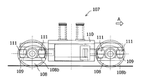
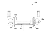
- a cart 107 is disposed below the vehicle body 106 of the leading vehicle 102.
- a pair of left and right wheels 108 are provided on the front side and the rear side of the carriage 107, respectively.
- the pair of wheels 108 are configured to be independently rotatable around the same axis 108 a extending in the vehicle width direction, and are connected by a shaft support member 109.
- the shaft support member 109 is disposed on the vehicle front side and the vehicle rear side of the bogie frame 110 configured as a frame body of the bogie 107, and wheels 108 are disposed between the shaft support member 109 and the bogie frame 110.
- a conical rubber 111 is provided as an axial spring.
- the conical rubber 111 suppresses vibrations transmitted from the wheel 108 to the carriage frame 110. Further, the shaft support member 109 extends at a position close to the road surface between the pair of wheels 108, and a floor surface (not shown) in the vehicle is disposed on the shaft support member 109. For this reason, the floor surface in the vehicle is close to the road surface.
- the attack angle ⁇ which is the angle of the traveling direction (indicated by arrow C) of the wheel 108 with respect to the tangential direction (indicated by arrow B) of the curved track
- the wheel flange 108b may come into contact with the track.
- pressure is applied to the vehicle from the wheel flange 108b, the lateral pressure of the vehicle increases, and vibration and creaking noise are generated in the vehicle.
- the ride comfort of the occupant is impaired, and consequently the wheel flange 108b. Has the problem of wear.
- the carriage 107 is configured to be movable in the vehicle width direction with respect to the vehicle body 106.
- a traction rod 112 that transmits the traction force of the carriage 107 to the vehicle body 106 is disposed along the vehicle front-rear direction, and the end of the traction rod 112 on the vehicle rear side is arranged.
- the portion 112a is attached to the carriage 107 via a spherical bush or vibration isolating rubber (not shown), and the end 112b of the tow rod 112 on the vehicle front side is provided with a spherical bush or vibration isolating rubber (not shown). Via the vehicle body 106 side.
- the leading vehicle 102 and the intermediate vehicle 103 turn around the pin connector 105 corresponding to the curvature radius R of the curved track 101 when traveling on the curved track of the vehicle.
- the leading vehicle 102 may not bend sufficiently with respect to the intermediate vehicle 103 due to the influence of the damper of the connecting portion 104.
- the wheel 108 may not bend along the curved track due to the influence of cant or slack of the curved track.
- the traveling direction of the wheel 108 (indicated by the arrow B) does not face the tangential direction (indicated by the arrow C) of the curved track 101, and the attack angle ⁇ may increase.
- the present invention has been made in view of such circumstances, and its purpose is to reduce the lateral pressure of the vehicle when traveling on a curved track of the vehicle, to prevent the generation of vehicle vibration and creaking noise, and boarding. It is an object of the present invention to provide a low-floor type vehicle that can improve the ride quality of a person and reduce the wear of wheel flanges.
- the low-floor type vehicle of the present invention is independent of each other around a carriage provided at a lower portion of the vehicle body, a carriage frame configured as a frame of the carriage, and the same axis extending in the vehicle width direction.
- a pair of wheels configured to be pivotable and traveling on a track, a shaft support member that connects the pair of wheels and is attached to the bogie frame, and a vehicle front and rear of the bogie frame from the shaft support member
- a carriage frame transverse beam arranged along the vehicle width direction at a position near the center of the direction, and the pair of wheels, the shaft support member and the carriage frame transverse beam are respectively arranged on the vehicle front side and the vehicle rear side of the carriage.
- a low-floor type vehicle wherein the pivot support member is configured to be turnable with respect to the bogie frame, and a connecting member that couples the pivot support member and the bogie frame lateral beam is provided;
- the connecting member is the vehicle width of the bogie frame transverse beam It is pivotably mounted about an axis extending in the vehicle height direction to the direction the central portion.
- a restoring rod or a horizontal damper arranged along the vehicle longitudinal direction and configured to be extendable in the vehicle longitudinal direction is provided on the carriage, and one end of the restoring rod or horizontal damper is the pivot member. The other end of the restoring rod or horizontal damper is attached to the bogie frame cross beam.
- an actuator that is disposed on at least one of the left and right outer sides of the connecting member in the vehicle width direction and that can reciprocate in the vehicle front-rear direction is provided in the carriage, and one end of the actuator is the shaft support member The other end portion of the actuator is attached to the carriage frame cross beam, and the operation of the actuator is controlled in accordance with the straight running state of the vehicle and the curved running state of the vehicle. Is configured to be turnable with respect to the bogie frame.
- the stopper member provided on the bogie frame is disposed on the outer side in the vehicle width direction of the connecting member so as to be able to contact the connecting member so as to restrict the rotation of the connecting member.
- the low-floor type vehicle of the present invention includes a carriage provided at a lower portion of the vehicle body, a carriage frame configured as a frame of the carriage, and the same axis extending in the vehicle width direction.
- a pair of wheels configured to be independently rotatable and traveling on a track; a shaft support member that connects the pair of wheels and that is attached to the bogie frame; and
- a carriage frame transverse beam disposed along the vehicle width direction at a position near the center in the vehicle longitudinal direction, and the pair of wheels, the shaft support member, and the carriage frame transverse beam are arranged on the vehicle front side and the vehicle rear side of the carriage.
- a pivot pin is attached to the portion so as to be rotatable about an axis extending in the vehicle height direction, and a coupling pin is provided at one end of the interlocking lever portion of the first coupling member and the second coupling member, A long hole extending in the vehicle front-rear direction is provided at the other tip of the interlocking lever portion of the first connecting member and the second connecting member, and the connecting pin and the long hole are engaged, Serial first coupling member and the second coupling member is configured to be rotatable in unison, the shaft support member is configured to be pivoted relative to the truck frame.
- a restoring rod or a horizontal damper arranged along the vehicle width direction and configured to be extendable and contractible in the vehicle width direction is provided in the carriage, and one end portion of the restoring rod or the horizontal damper is the interlocking lever portion. The other end of the restoring rod or horizontal damper is attached to the bogie frame.
- an actuator arranged along the vehicle width direction and configured to reciprocate in the vehicle width direction is provided in the carriage, and one end portion of the actuator includes the first connection member and the second connection member.
- the other end of the actuator is attached to the bogie frame, and controls the operation of the actuator corresponding to the straight running state of the vehicle and the curved running state of the vehicle.
- the shaft support member is configured to be rotatable with respect to the bogie frame.
- the low-floor type vehicle of the present invention is configured such that a carriage provided at a lower portion of a vehicle body, a carriage frame configured as a frame of the carriage, and independently rotatable about the same axis extending in the vehicle width direction. And a pair of wheels traveling on a track, a shaft support member connecting the pair of wheels and attached to the carriage frame, and a position closer to the center of the carriage frame in the vehicle front-rear direction than the shaft support member.
- a carriage frame transverse beam arranged along the vehicle width direction, and the pair of wheels, the shaft support member, and the carriage frame transverse beam are respectively provided on the vehicle front side and the vehicle rear side of the carriage.
- a floor-type vehicle wherein the shaft support member is configured to be turnable with respect to the bogie frame, and a connecting member that connects the shaft support member and the bogie frame lateral beam is provided, and the connection member is the bogie frame.
- Vehicle height in the middle of the cross beam in the vehicle width direction It mounted rotatably about an axis extending. Therefore, when the vehicle enters a curved track, when the outer side wheel of the pair of wheels comes into contact with the track and a force toward the inner side in the vehicle width direction is applied to the shaft support member, the shaft A support member will turn centering
- the wheel on the outer gauge side moves away from the center in the front-rear direction of the carriage, and the wheel on the inner gauge side of the pair of wheels moves toward the center in the front-rear direction of the carriage; Become.
- the wheel is in a state along the curved track and can enter the curved track with a small attack angle. Therefore, the contact pressure between the wheel on the outer track side and the track is relieved, the lateral pressure of the vehicle is reduced, and the vibration of the vehicle and the generation of creaking noise are prevented. Therefore, the ride comfort of the passenger is improved, and consequently wear of the wheel flange is reduced.
- a restoring rod or a horizontal damper arranged along the vehicle longitudinal direction and configured to be extendable in the vehicle longitudinal direction is provided on the carriage, and one end portion of the restoring rod or horizontal damper is provided. Is attached to the shaft support member, and the other end of the restoration rod or horizontal damper is attached to the bogie frame horizontal beam, and the shaft support member is moved by the restoration rod or horizontal damper when the vehicle runs on a curved track. It is possible to return from the rotated state to the state when the vehicle is traveling on a straight track. Furthermore, the restoring rod or the horizontal damper can absorb the swing of the shaft support member during linear track traveling, and the occurrence of the wheel swing due to the swing can be prevented. Therefore, the above-described effects can be obtained more reliably while improving the running stability of the vehicle while running on a straight track.
- an actuator that is disposed on at least one of the left and right outer sides of the connecting member in the vehicle width direction and that can reciprocate in the vehicle front-rear direction is provided on the carriage, and one end portion of the actuator Is attached to the shaft support member, and the other end portion of the actuator is attached to the bogie frame transverse beam, and the turning of the shaft support member can be controlled by the actuator. Therefore, for example, by operating the actuator corresponding to the curved track, the wheel attached to the shaft support member can be surely entered into the curved track with a small attack angle.
- the stopper member provided on the bogie frame is disposed outside the connecting member in the vehicle width direction so as to be able to contact the connecting member so as to restrict the rotation of the connecting member.
- the amount of rotation of the connecting member is limited by the stopper member, and as a result, the amount of turning of the shaft support member and the amount of movement of the wheel are limited. Therefore, the above-mentioned effect can be obtained more reliably while preventing the wheels from moving greatly and ensuring the running stability of the vehicle.
- the low-floor type vehicle of the present invention is capable of independently rotating around a carriage provided at the lower portion of the vehicle body, a carriage frame configured as a frame of the carriage, and the same axis extending in the vehicle width direction. And a pair of wheels that travel on the track, a shaft support member that connects the pair of wheels and that is attached to the carriage frame, and that is closer to the center of the carriage frame in the vehicle longitudinal direction than the shaft support member. And a pair of wheels, the shaft support member, and the carriage frame transverse beam are provided on the vehicle front side and the vehicle rear side of the carriage, respectively.
- a low-floor type vehicle wherein the pivot support member is configured to be turnable with respect to the bogie frame, and a connecting portion extending between the pivot support member and the bogie frame lateral beam on the vehicle front side; From the bogie frame to the center of the bogie frame A first connecting member having an interlocking lever portion extending along the vehicle front-rear direction toward the vehicle, and a connecting portion extending between the shaft support member and the carriage frame lateral beam on the vehicle rear side; A second connecting member having an interlocking lever portion extending along the vehicle front-rear direction toward the center of the bogie frame is provided, and the connecting portion extends in the vehicle height direction at the vehicle width direction central portion of the bogie frame lateral beam.
- the first connecting member and the second connecting member are provided with a connecting pin at one end portion of the interlocking lever portion, and the first connecting member and the second connecting member are pivotable about an extending axis.
- a long hole extending in the vehicle front-rear direction is provided at the other tip of the interlocking lever portion in the second connecting member, and the first connecting member and the long hole are engaged by engaging the connecting pin and the long hole.
- Serial second coupling member is configured to be rotatable in unison, the shaft support member is configured to be pivoted relative to the truck frame.
- the wheel on the outer track side of the pair of wheels contacts the track on the front side of the vehicle and heads inward in the vehicle width direction toward the shaft support member on the front side of the vehicle.
- the shaft support member turns around the attachment portion between the first connecting member and the carriage frame horizontal beam.
- the wheel on the outer track side moves toward the vehicle front side
- the wheel on the inner track side moves toward the vehicle rear side.
- the wheel is more surely along the curved track, and can enter the curved track with a small attack angle.
- the shaft support member on the vehicle front side turns, the first connection member and the second connection member rotate in conjunction with each other, and the shaft support member on the vehicle rear side turns the shaft support portion on the vehicle front side. It will turn in conjunction with the material. Therefore, even when the bogie receives the force acting on the vehicle body and the influence of cant and slack on the curved track, the shaft support members on the vehicle front side and the vehicle rear side do not move apart and move to the curved track. Correspondingly, they can turn in conjunction with each other reliably. As a result, the wheel provided on the shaft support member is more surely along the curved track, and can enter the curved track with a small attack angle.
- a restoring rod or a horizontal damper arranged along the vehicle width direction and configured to be extendable and contractible in the vehicle width direction is provided in the carriage, and one end portion of the restoring rod or the horizontal damper is the interlocking lever portion.
- the other end of the restoring rod or horizontal damper is attached to the bogie frame, and the first connecting member and the second connecting member are attached to the vehicle frame by the restoring rod or horizontal damper. It is possible to return from a state where the vehicle is rotated during the curved track traveling to a state during the linear track traveling of the vehicle.
- the restoring rod or the horizontal damper can also absorb the swing of the first connecting member and the second connecting member during linear track traveling, and the shaft support member and the The occurrence of wheel runout can be prevented. Therefore, the above-described effects can be obtained more reliably while improving the running stability of the vehicle while running on a straight track.
- an actuator arranged along the vehicle width direction and configured to reciprocate in the vehicle width direction is provided in the carriage, and one end portion of the actuator includes the first connection member and the second connection member.
- the other end of the actuator is attached to the carriage frame, and the rotation of the first connecting member and the second connecting member can be controlled by the actuator. ing. Therefore, for example, by operating the actuator corresponding to the curved track, the wheel linked to the first connecting member and the second connecting member can be more surely entered the curved track with a small attack angle. .
- a low floor type vehicle (hereinafter referred to as “vehicle”) according to a first embodiment of the present invention will be described below.
- vehicle a low floor type vehicle
- FIG. 1 an example of a vehicle will be described using an LRV as shown in FIG. 1, and the traveling direction of the vehicle will be described as the front of the vehicle.
- FIG. 1 the vehicle is viewed from above, and the traveling direction of the vehicle is indicated by an arrow A.
- the vehicle shown in FIG. 1 includes two leading vehicles 2 and one intermediate vehicle 3 that travel on the track 1, and one intermediate vehicle 3 is arranged between the two leading vehicles 2. It is organized.
- a connecting portion 4 is provided between the leading vehicle 2 and the intermediate vehicle 3, and a pin connecting device 5 is provided along the axis extending in the vehicle vertical direction at the connecting portion 4. It is connected to the vehicle 3 so as to be able to turn around the pin connector 5.
- a carriage 7 is provided below the vehicle body 6 of the leading vehicle 2, and wheels 8 provided on the carriage 7 are configured to travel on the track 1.
- the traveling direction of the vehicle is indicated by an arrow A.
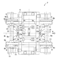
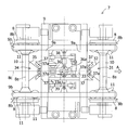
- the carriage 7 is provided with a carriage frame 9 as its frame, and the vehicle body 6 (shown in FIG. 1) is supported by the carriage frame 9.
- two bogie frame lateral beams 9 a extending in the vehicle width direction are arranged with an interval in the vehicle front-rear direction.
- two bogie frame vertical beams 9b extending in the vehicle front-rear direction are disposed on the bogie frame 9 so as to intersect with the two bogie frame horizontal beams 9a, respectively, and at intervals in the vehicle width direction.
- a shaft support member 10 is provided at each of the front end portion and the rear end portion of the bogie frame vertical beam 9b. Therefore, the bogie frame horizontal beam 9a is positioned closer to the center in the vehicle front-rear direction than the shaft support member 10.
- a pair of wheels 8 are attached to both ends of the shaft support member 10 in the vehicle width direction so as to be independently rotatable about the same axis line 8a. Is provided with a wheel flange 8b. Further, the shaft support member 10 is configured to extend close to the road surface between both ends to which the wheels 8 are attached.
- a conical rubber 11 is disposed as a shaft spring of the wheel 8 between the bogie frame vertical beam 9b and the end of the shaft support member 10, and the end of the shaft support member 10 is interposed via the cone rubber 11.
- the conical rubber 11 is configured to absorb vibration applied from the wheel 8 from the vertical direction of the vehicle, and to turn the shaft support member 10 with respect to the carriage frame 9.
- connecting members 12 for connecting the carriage frame lateral beam 9a and the shaft support member 10 are respectively disposed.
- the connecting member 12 is formed so as to spread in the vehicle width direction from the cart frame horizontal beam 9a toward the shaft support member 10, and is attached by a spherical bush at the center in the vehicle width direction of the cart frame horizontal beam 9a.
- a stopper member 13 is provided on the carriage frame horizontal beam 9a.
- the stopper member 13 is disposed at a distance from the outer edge of the connecting member 12 in the vehicle width direction so as to restrict the rotation of the connecting member 12 outside in the vehicle width direction to a certain amount.
- a stopper rubber 13 a is provided at a portion that comes into contact with the connecting member 12, and an impact at the time of contact between the connecting member 12 and the stopper member 13 can be reduced.
- 1st restoration rod 14 is provided in the vehicle width direction left and right outside of connecting member 12, respectively.
- a horizontal damper may be provided instead of the first restoring rod 14.
- the first restoring rod 14 is disposed in the vehicle front-rear direction outside the stopper member 13 in the vehicle width direction, and is configured to be extendable in the vehicle front-rear direction.
- One end of the first restoring rod 14 is attached to the shaft support member 10 so as to be rotatable about an axis extending in the vehicle vertical direction.
- the other end of the first restoring rod 14 is attached to the carriage frame horizontal beam 9a so as to be rotatable about an axis extending in the vehicle vertical direction.
- the first restoring rod 14 is in a free support state.
- the first restoring rod 14 is provided with a piston rod 15 extending along the longitudinal direction and a cylindrical cylinder 16 extending along the longitudinal direction.
- a head portion 15 a is provided at the distal end portion of the piston rod 15, and a cap portion 15 b is provided at the proximal end portion of the piston rod 15.
- the cap portion 15b is provided with a stopper portion 15c, and a rod portion 15d is provided between the head portion 15a and the cap portion 15b.
- the both ends 16a and 16b in the longitudinal direction of the cylinder 16 are formed so as to be closed.
- a through hole corresponding to the rod portion 15b of the piston rod 15 is provided in the end portion 16a on the head portion 15a side of the piston rod 15, and the end portion 16b of the piston rod 15 on the cap portion 15b side is provided with the cap portion 15b.
- Corresponding through holes are provided. Therefore, the cap portion 15 b and the rod portion 15 d of the piston rod 15 can be moved in the longitudinal direction within the cylinder 16.
- the head portion 15a of the piston rod 15 is in contact with the end portion 16a of the cylinder 16 on the head portion 15a side, and the piston rod 15 is restricted from moving in the longitudinal direction toward the cap portion 15b. .
- the stopper portion 15c of the piston rod 15 and the end portion 16b of the cylinder 16 located on the cap portion 15b side are arranged at a distance G from each other in the longitudinal direction. It can move up to a distance G in the longitudinal direction toward the portion 15a.
- a coil spring 17 is disposed in the cylinder 16 along the longitudinal direction
- a guide washer 18 is disposed between the coil spring 17 and the end portion 16b of the cylinder 16 located on the cap 15b side.
- the guide washer 18 is in contact with the cap portion 15b of the piston rod 15. When the cap portion 15b moves in the longitudinal direction toward the head portion 15a, the guide washer 18 moves together and the coil spring 17 is compressed. Will be.
- a rubber member 19 may be provided instead of the coil spring 17 as shown in FIG.
- the cap portion 15b of the piston rod 15 is arranged in a state of moving to the head portion 15a side, and such a state is the first restoring rod. 14 is in a neutral state. At this time, since the coil spring 17 is in a compressed state, a predetermined pressure is applied to the first restoring rod 14. With such a configuration, it is possible to provide the first restoring rod 14 that can be expanded and contracted in the vehicle front-rear direction even in a narrow space between the shaft support member 10 and the carriage frame lateral beam 9a.
- restoration rod 14 shown to Fig.3 (a) and FIG.3 (b) is only an example, and if it is a structure which can be expanded-contracted, another structure may be sufficient.
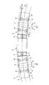
- FIG. 2 and FIG. 4 the vehicle is viewed from above, and the traveling direction of the vehicle is indicated by an arrow A.
- the leading vehicle 2 on the front side of the vehicle enters the curved track
- the pair of wheels 8 on the front side of the vehicle first enters the curved track
- the wheel flanges 8 b of the wheels 8 on the outer track side come into contact with the track 1.
- a force directed from the wheel flange 8b toward the inside in the vehicle width direction is applied to the shaft support member 10.
- the shaft support member 10 turns around the attachment portion between the connecting member 12 and the bogie frame cross beam 9a, the outer gauge side wheel 8 moves to the vehicle front side, and the inner gauge side wheel 8 moves to the rear of the vehicle. Will move to the side. Therefore, the pair of wheels 8 on the front side of the vehicle turn toward the front side of the vehicle by an angle ⁇ with respect to the center O of the curvature radius R of the curved track.
- the pair of wheels 8 on the rear side of the vehicle enters the curved track, and the wheel flange 8 b of the wheel 8 on the outer track side contacts the track 1.
- a force directed from the wheel flange 8b toward the inside in the vehicle width direction is applied to the shaft support member 10. Therefore, the shaft support member 10 turns around the attachment portion between the connecting member 12 and the bogie frame cross beam 9a, the outer gauge side wheel 8 moves to the vehicle rear side, and the inner gauge side wheel 8 moves to the vehicle front side. Will move to the side. Therefore, the pair of wheels 8 on the rear side of the vehicle turn toward the rear side of the vehicle by an angle ⁇ with respect to the center O of the curvature radius R of the curved track. As a result, the intermediate point 14 of the bogie frame 9 passes through the middle between the pair of tracks 1.
- the shaft support member 10 turns and the wheel 8 tries to move with a magnitude greater than a certain amount that makes the vehicle unstable, the shaft support portion.
- the connecting member 12 attached to the material 10 comes into contact with the stopper rubber 13a of the stopper member 13.
- the shaft support member 10 turns around the attachment portion between the coupling member 12 and the carriage frame lateral beam 9a.
- the pair of wheels 8 on the vehicle front side and the vehicle rear side turn together with the shaft support member 10 and travel along a curved track with a small attack angle ⁇ . Accordingly, the contact pressure between the wheel 8 on the outer track side and the track 1 is relieved, the lateral pressure of the vehicle is reduced, and the vibration of the vehicle and the generation of creaking noise are prevented. Therefore, the ride comfort of the passenger is improved, and consequently wear of the wheel flange 8b is reduced.
- the shaft support member 10 can be returned to the state when the vehicle is running on the straight track by the first restoring rod 14 from the rotated state when the vehicle is running on the curved track. ing. Further, the first restoring rod 14 can absorb the swinging of the shaft support member 10 during linear track traveling, and the occurrence of the swing of the wheel 8 due to such swinging can be prevented. Therefore, the running stability during the straight track running of the vehicle can be improved.
- the rotation amount of the connecting member 12 is limited by the stopper member 13, and as a result, the turning amount of the pivotal support member 10 and the movement amount of the wheel 8 are limited. . Therefore, it is possible to prevent a large movement of the wheels 8 and to ensure the running stability of the vehicle.
- a vehicle according to a second embodiment of the present invention will be described below.
- an LRV will be described as an example of the vehicle.
- the basic configuration of the vehicle according to the second embodiment is the same as the configuration of the vehicle according to the first embodiment. Elements similar to those in the first embodiment will be described using the same symbols and names as those in the first embodiment.
- a configuration different from the first embodiment will be described.
- the traveling direction of the vehicle is described as the front of the vehicle.
- an actuator 21 is provided instead of one of the pair of first restoring rods 14 provided on the vehicle front side and the vehicle rear side, respectively.
- both of the pair of first restoring rods 14 may be replaced with the actuator 21.
- Such an actuator 21 is disposed along the vehicle front-rear direction and is configured to be able to reciprocate in the vehicle front-rear direction.
- One end of the actuator 21 is attached to the shaft support member 10 so as to be rotatable about an axis extending in the vehicle vertical direction.
- the other end of the actuator 21 is attached to the carriage frame horizontal beam 9a so as to be rotatable about an axis extending in the vehicle vertical direction.
- the actuator 21 is in a neutral state.
- the vehicle In order to control the operation of the actuator 21, the vehicle is provided with a plurality of switches as shown in FIG. In FIG. 6, the vehicle is viewed from above, and the traveling direction of the vehicle is indicated by an arrow A. In the second embodiment, as an example, four switches 22, 23, 24, and 25 are used.
- the connecting portion 4 between the leading vehicle 2 and the intermediate vehicle 3 on the front side of the vehicle has a first switch 22 corresponding to the track 1 on the right side in the traveling direction and a second switch 23 corresponding to the track 1 on the left side in the traveling direction.
- the first switch 22 and the second switch 23 are configured so that the actuator 21 in the leading vehicle 2 on the front side of the vehicle is controlled.
- a third switch 24 corresponding to the track 1 on the right side in the traveling direction and a fourth switch 25 corresponding to the track 1 on the left side in the traveling direction are provided.
- the actuator 21 in the leading vehicle 2 on the side is configured to be controlled.
- the first to fourth switches 22, 23, 24, and 25 are all OFF as shown in FIG. At this time, the actuator 21 is not activated and is in a neutral state.
- FIG. 7 the vehicle is viewed from above, and the traveling direction of the vehicle is indicated by an arrow A.
- the first switch 22 and the third switch 24 on the inner track side of the right curved track are turned on, and the second switch 23 and the fourth switch 25 on the outer track side of the right curved track are turned off. Yes.
- the actuators 21 on the vehicle front side and the vehicle rear side perform an extending operation, respectively.
- the shaft support member 10 on the vehicle front side turns right so that the wheel 8 on the right side in the traveling direction moves to the vehicle rear side and the wheel 8 on the left side in the traveling direction moves to the vehicle front side.
- the shaft support member 10 on the vehicle rear side turns left so as to move the wheel 8 on the right side in the traveling direction to the vehicle front side and move the wheel 8 on the left side in the traveling direction to the vehicle rear side.
- the pair of wheels 8 on the vehicle front side turn toward the vehicle front side by an angle ⁇ with respect to the center O of the curvature radius R of the right curved track, and the pair of wheels 8 on the vehicle rear side
- the vehicle is turning toward the vehicle rear side by an angle ⁇ with respect to the center O of the curvature radius R of the curved track.
- FIG. 8 The case where the vehicle passes a left curved track that turns to the left in the traveling direction will be described with reference to FIG.
- the vehicle is viewed from above, and the traveling direction of the vehicle is indicated by an arrow A.
- the second switch 23 and the fourth switch 25 on the inner track side of the left curved track are turned on, and the first switch 22 and the third switch 24 on the outer track side of the left curved track are turned off. Yes.
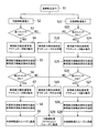
- the actuators 21 on the vehicle front side and the vehicle rear side perform a contracting operation, respectively.
- the shaft support member 10 on the vehicle front side turns left so as to move the wheel 8 on the right side in the traveling direction to the vehicle front side and move the wheel 8 on the left side in the traveling direction to the vehicle rear side.
- the shaft support member 10 on the vehicle rear side turns right so as to move the wheel 8 on the right side in the traveling direction to the vehicle rear side and move the wheel 8 on the left side in the traveling direction to the vehicle front side.
- the pair of wheels 8 and the shaft support member 10 on the vehicle front side turn toward the vehicle front side by an angle ⁇ with respect to the center O of the radius of curvature R of the left curved track, and the pair of vehicles on the vehicle rear side.
- the wheel 8 and the shaft support member 10 are turned toward the vehicle rear side by an angle ⁇ with respect to the center O of the radius of curvature R of the left curved track.
- the third switch 24 is turned on if the curvature radius R of the curved track is equal to or less than R100, and the third switch 24 is turned on if the curvature radius R of the curved track is equal to or greater than R100.
- the switch 24 remains OFF (S6).
- the actuator 21 extends in the leading vehicle 2 on the rear side of the vehicle (S7), and the shaft support portion on the front side of the vehicle
- the material 10 turns right, and the shaft support member 10 on the vehicle rear side turns left (S8).
- the vehicle smoothly passes the right curved track having a radius of curvature R100 or less (S9).
- the first switch 22 is turned off (S10), and the front vehicle 2 on the front side of the vehicle is in front of the vehicle.
- the actuator 21 on the side and the rear side of the vehicle returns to the neutral state (S11), and the shaft support member 10 on the front side of the vehicle and the rear side of the vehicle returns to the state at the time of linear track traveling (S12).
- the third switch 24 is turned OFF (S13), the actuator 21 on the vehicle front side and the vehicle rear side returns to the neutral state in the leading vehicle 2 on the vehicle rear side (S14), and the shafts on the vehicle front side and the vehicle rear side are returned.
- the support member 10 returns to the state during linear track traveling (S15). As a result, the vehicle smoothly advances on the right curved track having a radius of curvature R100 or less (S16), and travels on the straight track again (S17).
- the fourth switch 25 is turned on if the curvature radius R of the curved track is R100 or less, and the fourth switch 25 is set if the curvature radius R of the curved track is R100 or more.
- the switch 25 remains OFF (S26).
- the actuator 21 on the vehicle front side and the vehicle rear side in the leading vehicle 2 on the vehicle rear side is contracted (S27). )
- the pivot member 10 on the front side of the vehicle turns left
- the pivot member 10 on the rear side of the vehicle turns right (S28).
- the vehicle smoothly travels on the left curved track having a radius of curvature R100 or less (S29).
- the second switch 23 is turned OFF (S30), and the front vehicle 2 on the vehicle front side is in front of the vehicle.
- the side and vehicle rear side actuators 21 return to the neutral state (S31), and the vehicle front side and vehicle rear side shaft support members 10 return to the state during linear track traveling (S32).
- the fourth switch 25 is turned OFF (S33), the actuator 21 on the vehicle front side and the vehicle rear side returns to the neutral state in the leading vehicle 2 on the vehicle rear side (S34), and the shafts on the vehicle front side and the vehicle rear side are returned.
- the support member 10 returns to the state during linear track traveling (S35). As a result, the vehicle smoothly advances on the left curved track having a radius of curvature R100 or less (S36), and travels on the straight track again (S17).
- the turning of the shaft support member 10 can be controlled by the actuator 21. Therefore, for example, by operating the actuator 21 corresponding to the curved track, the wheel 8 attached to the shaft support member 10 can enter the curved track more reliably with a small attack angle.
- a vehicle according to a third embodiment of the present invention will be described below. Also in the third embodiment, description will be made using LRV as an example of a vehicle.
- the basic configuration of the vehicle according to the third embodiment is the same as the configuration of the vehicle according to the first embodiment. Elements similar to those in the first embodiment will be described using the same symbols and names as those in the first embodiment. Here, a configuration different from the first embodiment will be described.
- the traveling direction of the vehicle is described as the front of the vehicle.
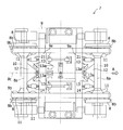
- a first connecting member 31 is disposed on the vehicle front side of the carriage 7.
- the first connecting member 31 is provided with a connecting portion 32 and an interlocking lever portion 33.
- the connecting portion 32 connects the shaft support member 10 and the bogie frame horizontal beam 9a, and is formed so as to spread in the vehicle width direction from the bogie frame horizontal beam 9a toward the shaft support member 10. It is attached by a spherical bush at the center in the vehicle width direction.
- the interlocking lever portion 33 is formed so as to extend along the vehicle front-rear direction from the vehicle frame side beam 9 a on the vehicle front side toward the center of the vehicle frame 9.
- a connecting pin 33a is provided at the distal end portion of the interlocking lever portion 33.
- the connecting pin 33a is on a vehicle axis 8c extending in the vehicle width direction at the center between the wheels 8 on the vehicle front side and the vehicle rear side. Has been placed.
- a second connecting member 34 is disposed on the vehicle rear side of the carriage 7.
- the second connecting member 34 is disposed to face the first connecting member 31.
- the second connecting member 34 is provided with a connecting portion 35 and an interlocking lever portion 36.
- the connecting portion 35 connects the shaft support member 10 and the vehicle frame side beam 9a on the vehicle rear side, and is formed so as to spread in the vehicle width direction from the vehicle frame side beam 9a toward the shaft support member 10.
- the frame cross beam 9a is attached by a spherical bush at the center in the vehicle width direction.
- the interlocking lever portion 36 is formed so as to extend along the vehicle front-rear direction from the vehicle frame side beam 9a on the vehicle front side toward the center of the vehicle frame 9.
- a long hole 36 a is formed in the distal end portion of the interlocking lever portion 36, and the long hole 36 a is formed so as to extend in the vehicle front-rear direction corresponding to the connection pin 33 a of the first connection member 31.
- the connecting pin 33a of the first connecting member 31 engages with the long hole 36a of the second connecting member 34, and is positioned at the center of the long hole 36a in the vehicle front-rear direction in a straight traveling state.
- a pair of stopper members 37 are provided on the vehicle frame lateral beam 9a on the vehicle front side and vehicle rear side, respectively.
- the stopper member 37 is configured so that the first connecting member 31 or the second connecting member 34 is connected to the first connecting member 32 or the second connecting member 34 so as to restrict the rotation of the first connecting member 31 or the second connecting member 34 in the vehicle width direction to a certain amount.
- the two connecting portions 35 are arranged at a distance from the outer edge in the vehicle width direction.
- a stopper rubber 37a is provided at a portion that contacts the connecting portion 32 or the connecting portion 35, and an impact at the time of contact between the first connecting member 31 or the second connecting member 34 and the stopper member 37 occurs. Mitigation is possible.
- the carriage 7 is provided with an actuator 38.
- the actuator 38 is arranged along the vehicle width direction and is configured to be able to reciprocate in the vehicle width direction.
- One end portion of the actuator 38 is attached to one of the interlocking lever portions 33 and 36 of the first connecting member 31 and the second connecting member 34 so as to be rotatable about an axis extending in the vehicle vertical direction.
- the other end of the actuator 38 is attached to the bogie frame vertical beam 9b on the left side in the traveling direction so as to be rotatable about an axis extending in the vehicle vertical direction.
- the actuator 38 is in a neutral state.
- the carriage 7 is provided with a second restoring rod 39 as an example.
- a horizontal damper may be provided instead of the second restoring rod 39.
- the second restoring rod 39 is arranged along the vehicle width direction and is configured to be extendable and contractible in the vehicle width direction.
- One end portion of the second restoring rod 39 is attached to one of the interlocking lever portions 33 and 36 of the first connecting member 31 and the second connecting member 34 so as to be rotatable about an axis extending in the vehicle vertical direction.
- the other end of the second restoring rod 39 is attached to the bogie frame vertical beam 9b on the right in the traveling direction so as to be rotatable about an axis extending in the vehicle vertical direction.
- the second restoring rod 39 is provided with a piston rod 40 extending along the longitudinal direction and a cylindrical cylinder 41 extending along the longitudinal direction.
- a head portion 40 a is provided at the distal end portion of the piston rod 40, and a cap portion 40 b is provided at the proximal end portion of the piston rod 40.
- a rod portion 40c extends between the head portion 40a and the cap portion 40b.
- a coil spring 42 is provided in the internal space of the cylinder 41.
- a concave portion 41a is provided on the inner peripheral wall of the internal space of the cylinder 41 so that the coil spring 42 can be disposed in a compressed state.
- the coil spring 42 is disposed in the concave portion 41a.
- guide washers 43 are disposed at both ends of the coil spring 42 in the vehicle width direction.
- the guide washer 43 is pressed against both ends in the vehicle width direction of the recess 41a by the pressure from the coil spring 42 in a compressed state.
- the rod portion 40c of the piston rod 40 is disposed so as to pass through the coil spring 42 and the guide washer 43.
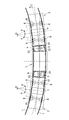
- the operation when traveling on a curved track will be described with reference to FIGS. 4 and 11.
- the pair of wheels 8 on the vehicle front side first enters the curved track, and the wheel flange 8b of the wheel 8 on the outer track side contacts the track 1.
- a force directed from the wheel flange 8b toward the inside in the vehicle width direction is applied to the shaft support member 10. Therefore, the pivotal support member 10 turns around the attachment portion between the connecting portion 32 of the first connecting member 31 and the bogie frame cross beam 9a, and the wheel 8 on the outer gauge side moves to the front side of the vehicle.
- the wheel 8 on the rail side moves to the vehicle rear side.
- the first connecting member 31 and the second connecting member 34 are rotated in conjunction with each other by the engagement between the connecting pin 33a of the first connecting member 31 and the long hole 36a of the second connecting member 34. Therefore, the shaft support member 10 on the rear side of the vehicle turns in the opposite direction to the shaft support member 10 on the front side of the vehicle, and the wheel 8 on the outer gauge side is on the vehicle rear side in the shaft support member 10 on the rear side of the vehicle. And the inner-rail side wheel 8 moves to the front side of the vehicle.
- the pair of wheels 8 and the shaft support member 10 on the vehicle front side turn toward the vehicle front side by an angle ⁇ with respect to the center O of the curvature radius R of the curved track, and the pair of wheels on the vehicle rear side. 8 and the shaft support member 10 are turned toward the vehicle rear side by an angle ⁇ with respect to the center O of the curvature radius R of the curved track.
- the intermediate point 14 of the bogie frame 9 passes through the middle between the pair of tracks 1.
- the vehicle of the third embodiment is provided with first to fourth switches 22, 23, 24, and 25 that are configured in the same manner as in the second embodiment.
- the control flow of the actuator 38 that accompanies the switching of the first to fourth switches 22, 23, 24, and 25 when the vehicle passes through the curved track of the third embodiment differs from the second embodiment in the following points. Yes.
- the first switch 22 When the first switch 22 is turned on, the actuator 38 contracts in the leading vehicle 2 on the front side of the vehicle, and when the third switch 24 is turned on, the actuator 38 on the leading vehicle 2 on the rear side of the vehicle. Will shrink.
- the second switch 23 is turned on, the actuator 38 extends in the leading vehicle 2 on the front side of the vehicle, and when the fourth switch 25 is turned on, the actuator 38 on the leading vehicle 2 on the vehicle rear side. Will stretch.
- the same effect as that of the first embodiment can be obtained, and the first connecting member 31 and the second connecting member 34 can rotate in conjunction with each other. Therefore, the shaft support member 10 on the vehicle rear side turns in conjunction with the shaft support member 10 on the vehicle front side. Therefore, even when the force acting on the vehicle body 6 and the influence of cant and slack on the curved track are affected, the shaft support members 10 on the vehicle front side and the vehicle rear side correspond to the curved track without moving apart. Can be turned in conjunction with each other. As a result, the wheel 8 provided on the shaft support member 10 is more surely along the curved track, and can enter the curved track with a small attack angle.
- the first connecting member 31 and the second connecting member 34 are moved by the second restoring rod 39 from a state where the first connecting member 31 and the second connecting member 34 are rotated when the vehicle is traveling on a curved track. It is possible to return to the state of. Further, the second restoring rod 39 can also absorb the swing of the first connecting member 31 and the second connecting member 34 when traveling on a straight track, and the shaft support member 10 and the wheel accompanying the swing are also supported. 8 can be prevented from occurring. Therefore, the running stability during the straight track running of the vehicle can be improved.
- the rotation of the first connecting member 31 and the second connecting member 34 can be controlled by the actuator 38. Furthermore, by operating the actuator 38 corresponding to the curved track, the wheel 8 linked to the first connecting member 31 and the second connecting member 34 can be more surely entered the curved track with a small attack angle.
- the top carriage 2 is provided with a carriage 7 and two leading vehicles 2 are arranged.
- the number of the leading vehicle 2 and the number of the intermediate vehicles 3 may be different as long as the intermediate vehicle 3 is arranged in between. The same effects as those described in the above embodiment can be obtained.
- an anti-vibration rubber may be provided instead of the guide washer 43 of the second restoration rod 39. Further, the swing of the first connecting member 31 and the second connecting member 34 can be absorbed, and the occurrence of the swing of the shaft support member 10 and the wheel 8 accompanying the swing can be effectively prevented.
- the control operation amount of the actuators 21 and 38 may be changed corresponding to the curvature radius R of the curved track.
- the wheels 8 follow the curved track more reliably, and the vehicle can travel on the curved track more smoothly.
- the timing at which the actuators 21 and 38 operate is determined in advance corresponding to the travel route that travels, and the timing corresponding to the determined timing is determined.
- the operations of the actuators 21 and 38 may be controlled.
- the wheels 8 are more surely along the curved track, and the vehicle can travel more along the track.
Landscapes
- Engineering & Computer Science (AREA)
- Mechanical Engineering (AREA)
- Platform Screen Doors And Railroad Systems (AREA)
- Vehicle Body Suspensions (AREA)
- Body Structure For Vehicles (AREA)
Abstract
Description
そのため、車両が曲線軌道に進入するときに、前記一対の車輪のうち外軌側の車輪が前記軌道と接触して、前記軸支部材に車幅方向内側に向かう力が加えられると、前記軸支部材が、前記連結部材と前記台車枠横梁との取付部を中心に旋回することとなる。このとき、外軌側の前記車輪が前記台車の前後方向中央から離れるように移動し、かつ、前記一対の車輪のうち内軌側の車輪が前記台車の前後方向中央に向かって移動することとなる。その結果、前記車輪は、曲線軌道に沿った状態となって、小さなアタック角で曲線軌道に進入できる。従って、外軌側の前記車輪と前記軌道との接触圧力が緩和され、車両の横圧が低減され、車両の振動およびキシリ音の発生が防止されることとなる。よって、搭乗者の乗り心地が改善され、ひいては車輪フランジの摩耗が低減されることとなる。
そのため、車両が曲線軌道に進入するときに、車両前方側において前記一対の車輪のうち外軌側の車輪が前記軌道と接触して、車両前方側の前記軸支部材に車幅方向内側に向かう力が加えられると、前記軸支部材が前記第1連結部材と前記台車枠横梁との取付部を中心に旋回することとなる。このとき、車両前方側の前記一対の車輪について、外軌側の前記車輪が車両前方側に向かって移動し、かつ、内軌側の車輪が車両後方側に向かって移動することとなる。その結果、前記車輪は、より確実に曲線軌道に沿った状態となって、小さなアタック角で曲線軌道に進入できる。
本発明の第1実施形態の低床式車両(以下、「車両」という)について以下に説明する。第1実施形態では、車両の一例として、図1で示すようなLRVを用いて説明するものとし、また、車両の進行方向を車両前方として説明する。図1は、車両を上方から見たものとし、車両の進行方向を矢印Aで示す。図1に示す車両では、軌道1上を走行する2台の先頭車両2および1台の中間車両3を備えており、2台の先頭車両2の間に1台の中間車両3を配置した車両編成となっている。先頭車両2と中間車両3との間には連接部4が設けられ、この連結部4には車両上下方向に延びる軸線に沿ってピン連接器5が設けられており、先頭車両2は、中間車両3に対してピン連接器5を中心に旋回可能に連結されている。先頭車両2の車体6の下部には台車7が設けられており、台車7に設けられた車輪8が軌道1上を走行するように構成されている。
車両前方側の先頭車両2が曲線軌道に進入する際、最初に車両前方側の一対の車輪8が曲線軌道に進入し、この外軌側の車輪8の車輪フランジ8bが軌道1に接触する。このとき、車輪フランジ8bから車幅方向内側に向かう力が軸支部材10に加えられる。そのため、軸支部材10が連結部材12と台車枠横梁9aとの取付部を中心に旋回し、外軌側の車輪8が車両前方側に移動し、かつ、内軌側の車輪8が車両後方側に移動することとなる。そのため、車両前方側の一対の車輪8は、曲線軌道の曲率半径Rの中心Oを基準に角度θ分、車両前方側に向かって旋回することとなる。
本発明の第2実施形態の車両について以下に説明する。第2実施形態でもまた、車両の一例としてLRVを用いて説明する。第2実施形態の車両の基本的な構成は、第1実施形態の車両の構成と同様になっている。第1実施形態と同様な要素は、第1実施形態と同様の符号および名称を用いて説明する。ここでは、第1実施形態と異なる構成について説明する。なお、第2実施形態では、車両の進行方向を車両前方として説明する。
図9を参照すると、車両前方側の先頭車両2が、直線軌道を走行している状態(S1)から、右曲線軌道に進入したとき(S2)、曲線軌道の曲率半径RがR100以下ならば第1スイッチ22がONとなり、曲線軌道の曲率半径RがR100以上ならば第1スイッチ22がOFFのままとなる(S3)。曲線軌道の曲率半径RがR100以下で第1スイッチ22がONとなった場合(S3)、車両前方側の先頭車両2において車両前方側および車両後方側のアクチュエータ21が伸び動作をして(S4)、車両前方側の軸支部材10が右旋回し、かつ車両後方側の軸支部材10が左旋回する(S5)。
図9を参照すると、車両前方側の先頭車両2が、直線軌道を走行している状態(S1)から、左曲線軌道に進入したとき(S22)、曲線軌道の曲率半径RがR100以下ならば第2スイッチ23がONとなり、曲線軌道の曲率半径RがR100以上ならば第2スイッチ23がOFFのままとなる(S23)。曲線軌道の曲率半径RがR100以下で第2スイッチ23がONとなった場合(S23)、車両前方側の先頭車両2において車両前方側および車両後方側のアクチュエータ21が縮み動作をして(S24)、車両前方側の軸支部材10が左旋回し、かつ車両後方側の軸支部材10が右旋回する(S25)。
本発明の第3実施形態の車両について以下に説明する。第3実施形態でもまた、車両の一例としてLRVを用いて説明する。第3実施形態の車両の基本的な構成は、第1実施形態の車両の構成と同様になっている。第1実施形態と同様な要素は、第1実施形態と同様の符号および名称を用いて説明する。ここでは、第1実施形態と異なる構成について説明する。なお、第3実施形態では、車両の進行方向を車両前方として説明する。
2 先頭車両
3 中間車両
4 連接部
5 ピン連接器
6 車体
7 台車
8 車輪
8a,8c 軸線
8b 車輪フランジ
9 台車枠
9a 台車枠横梁
9b 台車枠縦梁
10 軸支部材
11 円錐ゴム
12 連結部材
13,37 ストッパ部材
13a,37a ストッパゴム
14 第1復元ロッド
15 ピストンロッド
15a ヘッド部
15b キャップ部
15c ストッパ部
15d ロッド部
16 シリンダ
16a,16b 端部
17 コイルバネ
18 ガイド座金
19 ゴム部材
21,38 アクチュエータ
22 第1スイッチ
23 第2スイッチ
24 第3スイッチ
25 第4スイッチ
31 第1連結部材
32 連結部
33 連動レバー
33a 連結ピン
34 第2連結部材
35 連結部
36 連動レバー
36a 長孔
39 第2復元ロッド
40 ピストンロッド
40a ヘッド部
40b キャップ部
40c ロッド部
41 シリンダ
41a 凹部
42 コイルバネ
43 ガイド座金
A,B,C 矢印
D 距離
O 中心
α,β,θ 角度
Claims (7)
- 車体の下部に設けられる台車と、
前記台車の枠体として構成される台車枠と、
車幅方向に延びる同一軸線を中心としてそれぞれ独立して回動可能に構成され、かつ軌道上を走行する一対の車輪と、
前記一対の車輪を連結し、かつ前記台車枠に取付けられる軸支部材と、
前記軸支部材より前記台車枠の車両前後方向中央寄りの位置で車幅方向に沿って配置される台車枠横梁とを備え、
前記一対の車輪、前記軸支部材および前記台車枠横梁が、前記台車の車両前方側および車両後方側にそれぞれ設けられている、低床式車両であって、
前記軸支部材が前記台車枠に対して旋回可能に構成され、
前記軸支部材と前記台車枠横梁とを連結する連結部材が設けられ、
前記連結部材が前記台車枠横梁の車幅方向中央部に車両高さ方向に延びる軸線を中心として回動可能に取付けられている、低床式車両。 - 車両前後方向に沿って配置されるとともに車両前後方向に伸縮可能に構成される復元ロッドまたは水平ダンパが前記台車に設けられ、前記復元ロッドまたは水平ダンパの一端部が前記軸支部材に取付けられ、前記復元ロッドまたは水平ダンパの他端部が前記台車枠横梁に取付けられている、請求項1に記載の低床式車両。
- 前記連結部材の車幅方向左右外側の少なくとも一方に配置されるとともに車両前後方向に往復動作可能に構成されるアクチュエータが前記台車に設けられ、前記アクチュエータの一端部が前記軸支部材に取付けられ、前記アクチュエータの他端部が前記台車枠横梁に取付けられており、
車両の直線走行状態および車両のカーブ走行状態に対応して前記アクチュエータの動作を制御することによって、前記軸支部材が前記台車枠に対して旋回可能に構成されている、請求項1または2に記載の低床式車両。 - 前記台車枠に設けられるストッパ部材が、前記連結部材の回動を規制するように前記連結部材と当接可能に前記連結部材の車幅方向外側に配置されている、請求項1~3のいずれか一項に記載の低床式車両。
- 車体の下部に設けられる台車と、
前記台車の枠体として構成される台車枠と、
車幅方向に延びる同一軸線を中心としてそれぞれ独立して回動可能に構成され、かつ軌道上を走行する一対の車輪と、
前記一対の車輪を連結し、かつ前記台車枠に取付けられる軸支部材と、
前記軸支部材より前記台車枠の車両前後方向中央寄りの位置で車幅方向に沿って配置される台車枠横梁とを備え、
前記一対の車輪、前記軸支部材および前記台車枠横梁が、前記台車の車両前方側および車両後方側にそれぞれ設けられている、低床式車両であって、
前記軸支部材が前記台車枠に対して旋回可能に構成され、
車両前方側における前記軸支部材および前記台車枠横梁の間に延在する連結部と、前記台車枠から車両前記台車枠の中央に向かって車両前後方向に沿って延びる連動レバー部とを有する第1連結部材が設けられ、
車両後方側における前記軸支部材および前記台車枠横梁の間に延在する連結部と、前記台車枠から車両前記台車枠の中央に向かって車両前後方向に沿って延びる連動レバー部とを有する第2連結部材が設けられ、
前記連結部が前記台車枠横梁の車幅方向中央部に車両高さ方向に延びる軸線を中心として回動可能に取付けられており、
前記第1連結部材および前記第2連結部材における前記連動レバー部の一方の先端部には連結ピンが設けられ、
前記第1連結部材および前記第2連結部材における前記連動レバー部の他方の先端部には車両前後方向に延びる長孔が設けられ、
前記連結ピンと前記長孔とが係合することによって、前記第1連結部材および前記第2連結部材が同調して回動可能に構成され、前記軸支部材が前記台車枠に対して旋回可能に構成されている、低床式車両。 - 車幅方向に沿って配置されるとともに車幅方向に伸縮可能に構成される復元ロッドまたは水平ダンパが前記台車に設けられ、前記復元ロッドまたは水平ダンパの一端部が前記連動レバー部のいずれか一方に取りつけられ、前記復元ロッドまたは水平ダンパの他端部が前記台車枠に取り付けられている、請求項5に記載の低床式車両。
- 車幅方向に沿って配置されるとともに車幅方向に往復動作可能に構成されるアクチュエータが前記台車に設けられ、前記アクチュエータの一端部が前記第1連結部材および前記第2連結部材の連動レバー部のいずれか一方に取付けられ、前記アクチュエータの他端部が前記台車枠に取付けられており、
車両の直線走行状態および車両のカーブ走行状態に対応して前記アクチュエータの動作を制御することによって、前記軸支部材が前記台車枠に対して旋回可能に構成されている、請求項5または6に記載の低床式車両。
Priority Applications (5)
| Application Number | Priority Date | Filing Date | Title |
|---|---|---|---|
| HK12105280.4A HK1164807B (en) | 2009-02-20 | 2009-06-16 | Low floor vehicle |
| US13/148,731 US8776696B2 (en) | 2009-02-20 | 2009-06-16 | Low floor vehicle |
| KR1020117019210A KR101297905B1 (ko) | 2009-02-20 | 2009-06-16 | 저상식 차량 |
| SG2011060555A SG173811A1 (en) | 2009-02-20 | 2009-06-16 | Low-floor vehicle |
| CN200980158817.9A CN102405167B (zh) | 2009-02-20 | 2009-06-16 | 低地板式车辆 |
Applications Claiming Priority (2)
| Application Number | Priority Date | Filing Date | Title |
|---|---|---|---|
| JP2009037990A JP5010628B2 (ja) | 2009-02-20 | 2009-02-20 | 低床式車両 |
| JP2009-037990 | 2009-02-20 |
Publications (1)
| Publication Number | Publication Date |
|---|---|
| WO2010095286A1 true WO2010095286A1 (ja) | 2010-08-26 |
Family
ID=42633584
Family Applications (1)
| Application Number | Title | Priority Date | Filing Date |
|---|---|---|---|
| PCT/JP2009/060913 Ceased WO2010095286A1 (ja) | 2009-02-20 | 2009-06-16 | 低床式車両 |
Country Status (7)
| Country | Link |
|---|---|
| US (1) | US8776696B2 (ja) |
| JP (1) | JP5010628B2 (ja) |
| KR (1) | KR101297905B1 (ja) |
| CN (1) | CN102405167B (ja) |
| SG (1) | SG173811A1 (ja) |
| TW (1) | TW201031545A (ja) |
| WO (1) | WO2010095286A1 (ja) |
Families Citing this family (9)
| Publication number | Priority date | Publication date | Assignee | Title |
|---|---|---|---|---|
| JP5010629B2 (ja) * | 2009-02-20 | 2012-08-29 | 三菱重工業株式会社 | 低床式車両 |
| JP5322775B2 (ja) * | 2009-05-26 | 2013-10-23 | 川崎重工業株式会社 | 低床式鉄道車両用台車、それの固定車軸の圧入方法および取り外し方法 |
| JP2012056561A (ja) * | 2011-07-27 | 2012-03-22 | Masayuki Kawada | 鉄道車両用輪軸中央操舵装置 |
| WO2013061641A1 (ja) * | 2011-10-26 | 2013-05-02 | 新日鐵住金株式会社 | 鉄道車両用台車の操舵方法及び装置並びに台車 |
| US9388538B2 (en) * | 2014-06-09 | 2016-07-12 | Wirtgen Gmbh | Frame width adjustment by steering |
| US9248877B1 (en) * | 2014-09-11 | 2016-02-02 | Yamaha Hatsudoki Kabushiki Kaisha | Vehicle |
| US10427697B2 (en) * | 2017-07-04 | 2019-10-01 | Nordco Inc. | Rail pressure adjustment assembly and system for rail vehicles |
| GB2566715B (en) * | 2017-09-22 | 2020-05-20 | Bombardier Transp Gmbh | Rail vehicle provided with running gear with a steering actuator and associated control method |
| DE102019129457A1 (de) * | 2019-10-31 | 2021-05-06 | Liebherr-Transportation Systems Gmbh & Co Kg | Hydromechanisches Radsatzsteuerungssystem für ein Schienenfahrzeug |
Citations (9)
| Publication number | Priority date | Publication date | Assignee | Title |
|---|---|---|---|---|
| JPS61241259A (ja) * | 1985-04-17 | 1986-10-27 | 株式会社東芝 | 操舵台車 |
| JPH0234465A (ja) * | 1988-07-26 | 1990-02-05 | Railway Technical Res Inst | 鉄道車両用独立車輪付操舵台車 |
| JPH03258655A (ja) * | 1990-03-06 | 1991-11-18 | Railway Technical Res Inst | 輪軸ヨー角制御装置付鉄道用車両 |
| JPH0585358A (ja) * | 1991-09-26 | 1993-04-06 | Hitachi Ltd | 車両用輪軸操舵装置 |
| JPH0687446A (ja) * | 1992-09-10 | 1994-03-29 | Hitachi Ltd | 操舵台車 |
| JPH092263A (ja) * | 1995-06-20 | 1997-01-07 | Hitachi Ltd | 鉄道車両用台車 |
| JPH09226576A (ja) * | 1996-02-28 | 1997-09-02 | Hitachi Ltd | 鉄道車両用台車の車輪軸操舵装置 |
| JP2002211392A (ja) * | 2001-01-12 | 2002-07-31 | Kawasaki Heavy Ind Ltd | 鉄道車両用一軸台車 |
| JP2004161115A (ja) * | 2002-11-12 | 2004-06-10 | National Traffic Safety & Environment Laboratory | 台車枠旋回装置付鉄道車両 |
Family Cites Families (10)
| Publication number | Priority date | Publication date | Assignee | Title |
|---|---|---|---|---|
| US4655143A (en) * | 1974-01-31 | 1987-04-07 | Railway Engineering Associates, Inc. | Articulated trucks |
| US4542699A (en) * | 1983-11-25 | 1985-09-24 | Urban Transportation Development Corporation Ltd. | Powered radial truck |
| JPH0291070U (ja) | 1989-01-06 | 1990-07-19 | ||
| DE4238574A1 (de) * | 1992-11-16 | 1994-05-19 | Abb Henschel Waggon Union | Fahrwerk für Niederflurbahnen |
| DE19538379C1 (de) | 1995-10-14 | 1997-01-02 | Daimler Benz Ag | Zweirädiges Fahrwerk für spurgeführte Fahrzeuge |
| CN2515076Y (zh) * | 2001-12-28 | 2002-10-09 | 湘潭电机股份有限公司 | 低地板轻轨车拖动转向架 |
| JP4838693B2 (ja) * | 2006-11-27 | 2011-12-14 | 三菱重工業株式会社 | 軌道系交通システム |
| JP4979374B2 (ja) * | 2006-12-28 | 2012-07-18 | 川崎重工業株式会社 | 低床式鉄道車両用台車 |
| CN201092323Y (zh) * | 2007-11-02 | 2008-07-30 | 长春轨道客车股份有限公司 | 一种用于城市低地板轻轨车的独立轮转向架 |
| JP5010629B2 (ja) * | 2009-02-20 | 2012-08-29 | 三菱重工業株式会社 | 低床式車両 |
-
2009
- 2009-02-20 JP JP2009037990A patent/JP5010628B2/ja not_active Expired - Fee Related
- 2009-06-16 WO PCT/JP2009/060913 patent/WO2010095286A1/ja not_active Ceased
- 2009-06-16 US US13/148,731 patent/US8776696B2/en not_active Expired - Fee Related
- 2009-06-16 KR KR1020117019210A patent/KR101297905B1/ko not_active Expired - Fee Related
- 2009-06-16 SG SG2011060555A patent/SG173811A1/en unknown
- 2009-06-16 CN CN200980158817.9A patent/CN102405167B/zh not_active Expired - Fee Related
- 2009-07-13 TW TW098123622A patent/TW201031545A/zh unknown
Patent Citations (9)
| Publication number | Priority date | Publication date | Assignee | Title |
|---|---|---|---|---|
| JPS61241259A (ja) * | 1985-04-17 | 1986-10-27 | 株式会社東芝 | 操舵台車 |
| JPH0234465A (ja) * | 1988-07-26 | 1990-02-05 | Railway Technical Res Inst | 鉄道車両用独立車輪付操舵台車 |
| JPH03258655A (ja) * | 1990-03-06 | 1991-11-18 | Railway Technical Res Inst | 輪軸ヨー角制御装置付鉄道用車両 |
| JPH0585358A (ja) * | 1991-09-26 | 1993-04-06 | Hitachi Ltd | 車両用輪軸操舵装置 |
| JPH0687446A (ja) * | 1992-09-10 | 1994-03-29 | Hitachi Ltd | 操舵台車 |
| JPH092263A (ja) * | 1995-06-20 | 1997-01-07 | Hitachi Ltd | 鉄道車両用台車 |
| JPH09226576A (ja) * | 1996-02-28 | 1997-09-02 | Hitachi Ltd | 鉄道車両用台車の車輪軸操舵装置 |
| JP2002211392A (ja) * | 2001-01-12 | 2002-07-31 | Kawasaki Heavy Ind Ltd | 鉄道車両用一軸台車 |
| JP2004161115A (ja) * | 2002-11-12 | 2004-06-10 | National Traffic Safety & Environment Laboratory | 台車枠旋回装置付鉄道車両 |
Also Published As
| Publication number | Publication date |
|---|---|
| TW201031545A (en) | 2010-09-01 |
| JP2010188962A (ja) | 2010-09-02 |
| KR101297905B1 (ko) | 2013-08-22 |
| KR20110110325A (ko) | 2011-10-06 |
| SG173811A1 (en) | 2011-09-29 |
| US8776696B2 (en) | 2014-07-15 |
| CN102405167B (zh) | 2015-03-04 |
| CN102405167A (zh) | 2012-04-04 |
| JP5010628B2 (ja) | 2012-08-29 |
| HK1164807A1 (en) | 2012-09-28 |
| US20120048139A1 (en) | 2012-03-01 |
Similar Documents
| Publication | Publication Date | Title |
|---|---|---|
| JP5010628B2 (ja) | 低床式車両 | |
| JP5010630B2 (ja) | 低床式車両 | |
| JP5010629B2 (ja) | 低床式車両 | |
| KR101297938B1 (ko) | 궤도계 차량용 대차 | |
| KR101252979B1 (ko) | 궤도계 차량용 대차 | |
| JP2010215120A (ja) | 軌道系車両用台車 | |
| JP5127412B2 (ja) | 車体間アンチロール装置及び鉄道車両 | |
| WO2008059604A1 (en) | Truck structure of track-type vehicle | |
| JP4012614B2 (ja) | 鉄道車両用車体傾斜装置付き台車 | |
| JPH08142862A (ja) | 鉄道車両用台車 | |
| JP5562882B2 (ja) | 鉄道車両 | |
| JP4758681B2 (ja) | 車両用緩衝装置及びこれを備えるデュアルモード車両 | |
| HK1164808B (en) | Low floor vehicle | |
| HK1164807B (en) | Low floor vehicle | |
| HK1159571B (en) | Low floor vehicle |
Legal Events
| Date | Code | Title | Description |
|---|---|---|---|
| WWE | Wipo information: entry into national phase |
Ref document number: 200980158817.9 Country of ref document: CN |
|
| 121 | Ep: the epo has been informed by wipo that ep was designated in this application |
Ref document number: 09840390 Country of ref document: EP Kind code of ref document: A1 |
|
| ENP | Entry into the national phase |
Ref document number: 20117019210 Country of ref document: KR Kind code of ref document: A |
|
| NENP | Non-entry into the national phase |
Ref country code: DE |
|
| WWE | Wipo information: entry into national phase |
Ref document number: 13148731 Country of ref document: US |
|
| 122 | Ep: pct application non-entry in european phase |
Ref document number: 09840390 Country of ref document: EP Kind code of ref document: A1 |