WO2010087080A1 - 電流検出装置 - Google Patents
電流検出装置 Download PDFInfo
- Publication number
- WO2010087080A1 WO2010087080A1 PCT/JP2009/070838 JP2009070838W WO2010087080A1 WO 2010087080 A1 WO2010087080 A1 WO 2010087080A1 JP 2009070838 W JP2009070838 W JP 2009070838W WO 2010087080 A1 WO2010087080 A1 WO 2010087080A1
- Authority
- WO
- WIPO (PCT)
- Prior art keywords
- bus bar
- magnetic field
- adjacent
- region
- bus bars
- Prior art date
- Legal status (The legal status is an assumption and is not a legal conclusion. Google has not performed a legal analysis and makes no representation as to the accuracy of the status listed.)
- Ceased
Links
Images





Classifications
-
- G—PHYSICS
- G01—MEASURING; TESTING
- G01R—MEASURING ELECTRIC VARIABLES; MEASURING MAGNETIC VARIABLES
- G01R15/00—Details of measuring arrangements of the types provided for in groups G01R17/00 - G01R29/00, G01R33/00 - G01R33/26 or G01R35/00
- G01R15/14—Adaptations providing voltage or current isolation, e.g. for high-voltage or high-current networks
- G01R15/20—Adaptations providing voltage or current isolation, e.g. for high-voltage or high-current networks using galvano-magnetic devices, e.g. Hall-effect devices, i.e. measuring a magnetic field via the interaction between a current and a magnetic field, e.g. magneto resistive or Hall effect devices
- G01R15/207—Constructional details independent of the type of device used
-
- G—PHYSICS
- G01—MEASURING; TESTING
- G01R—MEASURING ELECTRIC VARIABLES; MEASURING MAGNETIC VARIABLES
- G01R19/00—Arrangements for measuring currents or voltages or for indicating presence or sign thereof
- G01R19/0092—Measuring current only
Definitions
- the present invention relates to a current detection device that uses at least one of a plurality of bus bars arranged in parallel as a target bus bar and detects a current flowing through the target bus bar based on a magnetic field in the vicinity of the target bus bar.
- This current detection device includes, for example, three bus bars arranged in parallel with each other as a target bus bar, and includes three current sensors that detect a current flowing through each bus bar.
- the current detection device includes a magnetic shield attached to each bus bar.
- the three current sensors are arrange
- the magnetic shields attached to the bus bars are also arranged at positions shifted alternately along the bus bars. The arrangement of the plurality of magnetic shields and the plurality of current sensors is a so-called staggered arrangement, and thereby, magnetic interference from the adjacent bus bar to the current sensor can be avoided.
- the present invention has been made in view of the above problems, and when a plurality of bus bars are arranged in parallel, it is possible to detect current with high accuracy while suppressing the influence of a magnetic field from adjacent bus bars.
- An object of the present invention is to realize a simple current detection device at a low cost by a simple configuration in which the shape and arrangement of each part of the bus bar are appropriately set.
- At least one of a plurality of bus bars arranged in parallel is set as a target bus bar, and a current for detecting a current flowing through the target bus bar based on a magnetic field in the vicinity of the target bus bar
- a characteristic configuration of the detection device is that a sensor unit that detects a magnetic field in a predetermined magnetic field detection direction has an approximate direction of the magnetic field detection direction and an extension direction of the target bus bar at the detection site in the vicinity of the detection site of the target bus bar.
- a bus bar that is arranged in an orthogonal direction and is adjacent to the target bus bar among the plurality of bus bars is an adjacent bus bar, and a plane that is orthogonal to the extending direction of each part of the adjacent bus bar As an extended orthogonal surface, there is no one that passes through the sensor unit in a direction parallel to the magnetic field detection direction in the extended orthogonal surface of each part of the adjacent bus bar. Lies in the extending direction of each portion of the adjacent bus bars for said sensor unit is set.
- the state where the sensor unit is arranged in the vicinity of the detection part of the target bus bar means that the sensor part is arranged in contact with the detection part of the target bus bar or is separated from the detection part by a predetermined distance.
- the predetermined distance here is set within a distance in which the magnetic field generated from the target bus bar can be detected by the sensor unit.
- the magnetic flux of the magnetic field generated from each part of the bus bar basically passes through the extending orthogonal plane orthogonal to the extending direction of the corresponding part.
- the magnetic flux of the magnetic field does not pass through the sensor unit in a direction parallel to the magnetic field detection direction of the sensor unit.
- this current detection device the current flowing through the target bus bar can be detected with high accuracy. Moreover, according to this characteristic structure, it can suppress that the magnetic field from an adjacent bus bar exerts an influence on a sensor part by the simple structure which sets only the extension direction of each site
- the extending direction of each part of the adjacent bus bar with respect to the sensor part is set so that none of the extending orthogonal planes of the part of the adjacent bus bar passes through the sensor part. Is preferred.
- the adjacent to the sensor unit such that a portion passing through the sensor unit in the extending orthogonal plane of each part of the adjacent bus bar passes through the sensor unit in a direction crossing the magnetic field detection direction. Even if the extending direction of each part of the bus bar is set, it is preferable.
- the portion is generated from each portion of the adjacent bus bar.
- the magnetic flux of the magnetic field basically passes through the sensor unit in a direction that intersects the magnetic field detection direction of the sensor unit.
- the magnetic field from the adjacent bus bar detected by the sensor unit is only the vector component in the magnetic field detection direction for the magnetic field. Therefore, since it can suppress that the magnetic field from an adjacent bus bar is detected by a sensor part, it becomes possible to detect the magnetic field which generate
- the extending orthogonal surface passing through the sensor unit is in a direction substantially orthogonal to the magnetic field detection direction. It is more preferable that the sensor unit is set so as to pass through.
- the part of the extending orthogonal plane of each part of the adjacent bus bar that passes through the sensor part passes through the sensor part in a direction substantially orthogonal to the magnetic field detection direction, it is generated from each part of the adjacent bus bar.
- the magnetic flux of the magnetic field to be passed basically passes through the sensor unit in a direction substantially orthogonal to the magnetic field detection direction of the sensor unit.
- the vector component in the magnetic field detection direction for the magnetic field from the adjacent bus bar detected by the sensor unit is basically zero. Accordingly, since it is possible to greatly suppress the detection of the magnetic field from the adjacent bus bar by the sensor unit, the magnetic field generated from the target bus bar by the sensor unit can be detected with higher accuracy. Therefore, according to this current detection device, the current flowing through the target bus bar can be detected with high accuracy.
- Each of the plurality of bus bars has a one-side parallel region on one side of a predetermined reference direction and having an extending direction parallel to the reference direction, and the reference direction with respect to the one-side parallel region
- the other side parallel region having an extending direction parallel to the reference direction, and at least one of the plurality of bus bars is between the one side parallel region and the other side parallel region.
- the direction of the extending orthogonal surface of the bent region of at least one of the plurality of bus bars is the direction of the extending orthogonal surface of the one side parallel region or the other side parallel region of the other adjacent bus bar.
- the magnetic field detection direction and the extension orthogonal surface of each part of the adjacent bus bar are It becomes easy to set the extending direction of each part of the adjacent bus bar with respect to the sensor unit so that there is no one passing through the sensor unit in a parallel direction. Therefore, it is not necessary to provide a special configuration such as a magnetic shield in order to ensure detection accuracy, and a current detection device that can detect current with high accuracy with a simple and inexpensive configuration can be provided.
- the target bus bar has the bent region and the detection site is provided in the bent region.
- the sensor unit is arranged in the direction in which the extending direction of the bent area and the magnetic field detection direction are substantially orthogonal to each other in the vicinity of the bent area of the target bus bar.
- the magnetic field detection direction of a sensor part can be made into the direction which cross
- all of the plurality of bus bars have the bent region having the same direction as the extending direction, and the bent region of the adjacent bus bar has the sensor portion in the extending direction of the bent region. More preferably, they are arranged so as not to overlap.
- overlap in a predetermined direction is used as a concept representing a state in which at least a part of two members or regions are arranged at the same position with respect to the arrangement in the direction.
- the state in which two members or regions are “overlapped” in a predetermined direction means that at least two members or regions at least on the position on the coordinate axis parallel to the direction, regardless of the position on the coordinate axis orthogonal to the direction. This represents a state in which a part is the same position.
- the extending orthogonal planes of the respective parts in the bending area of the adjacent bus bar are parallel to the magnetic field detection direction of the sensor unit provided with the bending area of the target bus bar as the detection part.
- the bent regions of the plurality of bus bars are arranged so that none of the extending orthogonal surfaces of the respective portions in the bent region passes through the sensor portion.
- region becomes the direction which cross
- the sensor unit is arranged in a direction parallel to the magnetic field detection direction in the extending orthogonal plane of each part of the adjacent bus bar by a simple configuration in which each of the plurality of bus bars is provided with a bent region having the same direction as the extending direction. It can be set as the structure which does not pass through.
- the extending direction of the bent region is set in a direction substantially orthogonal to the reference direction.
- each bent region of the plurality of bus bars is arranged so that there is no one passing through the sensor portion in the extending orthogonal plane of each part in the bent region of the adjacent bus bar.
- region becomes the direction substantially orthogonal to the magnetic field detection direction of a sensor part. Therefore, the vector component in the magnetic field detection direction for the magnetic field from the adjacent bus bar detected by the sensor unit can be obtained by simply providing each of the plurality of bus bars with a bent region having a direction extending substantially orthogonal to the reference direction. Can be essentially zero. Therefore, it can suppress significantly that the magnetic field from an adjacent bus bar is detected by a sensor part.
- the two adjacent bus bars have the bending region in which different directions extend in the respective directions. is there.
- the adjacent orthogonal planes of the respective portions in the bent region of the adjacent bus bar are adjacent to each other such that the crossing direction is perpendicular to the magnetic field detection direction of the sensor unit provided with the bent region of the target bus bar as the detection portion.
- the bent areas of the two bus bars are arranged.
- region of an adjacent bus bar also becomes the direction which cross
- the sensor unit is arranged in a direction parallel to the magnetic field detection direction in the extending orthogonal plane of each part of the adjacent bus bar by a simple configuration in which each of the plurality of bus bars has a bent region extending in a different direction. It can be set as the structure which does not pass through.
- all of the plurality of bus bars have the bent region, and the one side parallel region and the other side parallel region of the adjacent bus bar are arranged so as not to overlap the sensor portion in the reference direction. Is preferred.
- the bent area of the target bus bar is disposed adjacent to the bent area of the adjacent bus bar, and the extending orthogonal planes of the portions of the bent area of the adjacent bus bar are directed to the bent area of the target bus bar.
- the surface is inclined toward the one side of the reference direction or the other side of the reference direction with respect to the direction of heading.
- the sensor unit passes through the extending orthogonal surface of each part of the adjacent bus bar. It is possible to easily realize a configuration in which there is nothing to be performed, or a configuration in which one that passes through the sensor unit among the extended orthogonal planes of each portion of the adjacent bus bar passes through the sensor unit in a direction intersecting the magnetic field detection direction. it can.
- the plurality of bus bars are composed of members having the same shape.
- the center lines of the plurality of bus bars are arranged in the same plane. According to this configuration, it becomes easy to arrange a plurality of bus bars in a relatively narrow space.
- each of the above-described configurations according to the present invention can be suitably used for a driving device for a rotating electrical machine driven by a three-phase alternating current, and in this case, the plurality of bus bars drive the rotating electrical machine. It is preferable that three bus bars through which three-phase alternating current flows flow and at least two of the three bus bars are the target bus bars.
- the “rotary electric machine” is used as a concept including a motor (electric motor), a generator (generator), and a motor / generator that functions as both a motor and a generator as necessary.
- each of the above-described configurations according to the present invention can suppress the detection of the magnetic field from the adjacent bus bar by the sensor unit as described above. Therefore, the sensor unit is a coreless type that does not include the magnetic collecting core. It is particularly suitable for a configuration that includes a magnetic field detection sensor and does not include a shield against an external magnetic field other than the magnetic field generated by the target bus bar.
- At least one of a plurality of bus bars arranged in parallel is set as a target bus bar, and a further characteristic configuration of a current detection device that detects a current flowing through the target bus bar based on a magnetic field in the vicinity of the target bus bar
- a sensor unit for detecting a magnetic field in a predetermined magnetic field detection direction is disposed in the vicinity of the detection part of the target bus bar in a direction in which the extension direction of the target bus bar at the detection part and the magnetic field detection direction are substantially orthogonal to each other.
- Each of the plurality of bus bars has a one side parallel region on one side of a predetermined reference direction and having an extending direction parallel to the reference direction, and the reference direction with respect to the one side parallel region
- the other side parallel region having an extending direction parallel to the reference direction
- at least the target bus bar includes the one side parallel region and the other side flat surface. Between the regions, it has a bent region to the extending direction of the direction different from the reference direction, in that the detection site is provided in the bent region.
- the magnetic field detection direction of the sensor unit in which the detection portion is provided in the bent region of the target bus bar is set to a direction intersecting the direction of the extending orthogonal plane of the one side parallel region and the other side parallel region of the adjacent bus bar. be able to.
- the extending direction of each part of the adjacent bus bar with respect to the sensor part is set so that none of the extending orthogonal surfaces of each part of the adjacent bus bar passes through the sensor part in a direction parallel to the magnetic field detection direction. It becomes easy. Therefore, according to this characteristic configuration, it is possible to suppress the magnetic field from the adjacent bus bar from affecting the sensor unit with a simple configuration, so there is no need to provide a special configuration such as a magnetic shield in order to ensure detection accuracy. Thus, a current detection device capable of detecting current with high accuracy with an inexpensive configuration can be provided.
- all of the plurality of bus bars have the bent region having the same direction as the extending direction, and the bent region of the adjacent bus bar arranged adjacent to the target bus bar includes the bent region. It is more preferable that it is arranged so as not to overlap with the sensor part in the extending direction.
- the extending orthogonal planes of the respective parts in the bending area of the adjacent bus bar are parallel to the magnetic field detection direction of the sensor unit provided with the bending area of the target bus bar as the detection part.
- the bent regions of the plurality of bus bars are arranged so that none of the extending orthogonal surfaces of the respective portions in the bent region passes through the sensor portion.
- region becomes the direction which cross
- the sensor unit is arranged in a direction parallel to the magnetic field detection direction in the extending orthogonal plane of each part of the adjacent bus bar by a simple configuration in which each of the plurality of bus bars is provided with a bent region having the same direction as the extending direction. It can be set as the structure which does not pass through.
- the extending direction of the bent region is set in a direction substantially orthogonal to the reference direction.
- each bent region of the plurality of bus bars is arranged so that there is no one passing through the sensor portion in the extending orthogonal plane of each part in the bent region of the adjacent bus bar.
- region becomes the direction substantially orthogonal to the magnetic field detection direction of a sensor part. Therefore, the vector component in the magnetic field detection direction for the magnetic field from the adjacent bus bar detected by the sensor unit can be obtained by simply providing each of the plurality of bus bars with a bent region having a direction extending substantially orthogonal to the reference direction. Can be essentially zero. Therefore, it can suppress significantly that the magnetic field from an adjacent bus bar is detected by a sensor part.
- the target bus bar and the adjacent bus bar arranged adjacent to the target bus bar have the bent region with different directions extending from each other.
- the target bus bar is such that the extending orthogonal planes of the respective parts in the bent area of the adjacent bus bar are in a direction intersecting the magnetic field detection direction of the sensor unit provided with the bent area of the target bus bar as the detection part.
- region of an adjacent bus bar will be arrange
- region of an adjacent bus bar also becomes the direction which cross
- the extending direction is parallel to the magnetic field detection direction in the extending orthogonal plane of each part of the adjacent bus bar. It can be set as the structure which does not pass a sensor part.
- all of the plurality of bus bars have the bent region, and the one side parallel region and the other side parallel region of the adjacent bus bar arranged adjacent to the target bus bar are connected to the sensor unit in the reference direction. It is preferable that they are arranged so as not to overlap.
- the bent area of the target bus bar is disposed adjacent to the bent area of the adjacent bus bar, and the extending orthogonal planes of the portions of the bent area of the adjacent bus bar are directed to the bent area of the target bus bar.
- the surface is inclined toward the one side of the reference direction or the other side of the reference direction with respect to the direction of heading.
- the sensor unit passes through the extending orthogonal surface of each part of the adjacent bus bar. It is possible to easily realize a configuration in which there is nothing to be performed, or a configuration in which one that passes through the sensor unit among the extended orthogonal planes of each portion of the adjacent bus bar passes through the sensor unit in a direction intersecting the magnetic field detection direction. it can.
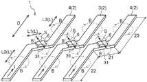
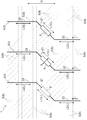
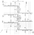
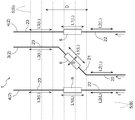
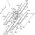
- FIG. 1 shows an example of the drive device of the rotary electric machine which concerns on embodiment of this invention. It is a perspective view which shows the 1st specific example of the arrangement configuration of the electric current detection apparatus which concerns on embodiment of this invention. It is a plane schematic diagram which shows the 1st specific example of the arrangement configuration of the current detection apparatus which concerns on embodiment of this invention. It is a plane schematic diagram which shows the 2nd specific example of the arrangement configuration of the current detection apparatus which concerns on embodiment of this invention. It is a plane schematic diagram which shows the 3rd specific example of the arrangement configuration of the current detection apparatus which concerns on embodiment of this invention. It is a plane schematic diagram which shows the 4th specific example of the arrangement configuration of the current detection apparatus which concerns on embodiment of this invention.
- the current detection device 1 uses at least one of a plurality of bus bars 2 arranged in parallel as a target bus bar 3, and based on a magnetic field B in the vicinity of the target bus bar 3. This is a device for detecting the current I flowing through the target bus bar 2.
- the current detection device 1 passes through the sensor unit 6 in a direction parallel to the magnetic field detection direction S of the sensor unit 6 in the extending orthogonal plane 5 of each part of the adjacent bus bar 4 disposed adjacent to the target bus bar 3.
- each bus bar 2 is configured by a conductive member such as copper formed in a strip shape having a substantially constant width.
- the extending direction L of each part of the bus bar 2 is a direction parallel to the longitudinal direction of each part of the bus bar 2, and is a direction parallel to the center line of the bus bar 2 in this embodiment.
- bus bar 2 is used as a general term for the target bus bar 3 and the adjacent bus bar 4, and the U-phase bus bar 2U, the V-phase bus bar 2V, and the W-phase bus bar 2W. Further, when simply referred to as the sensor unit 6, all of the U-phase sensor unit 6U, the V-phase sensor unit 6V, and the W-phase sensor unit 6W are collectively referred to.
- the current detection device 1 is configured to include three bus bars 2U, 2V, and 2W through which currents of respective phases of three-phase alternating current for driving the rotating electrical machine MG flow.
- detection parts 31 are set in all three bus bars 2U, 2V, and 2W, and sensor units 6U, 6V, and 6W are provided in the vicinity of the detection parts 31, respectively. .
- the target bus bar 3 is a bus bar 2 in which a detection part 31 is set at a predetermined position and a sensor unit 6 for detecting a magnetic field is provided in the vicinity of the detection part 31. Accordingly, in the present embodiment, all of the three bus bars 2U, 2V, 2W are the target bus bar 3. When any one of these three bus bars 2U, 2V, and 2W is focused on as the target bus bar 3, the other bus bar 2 disposed adjacent to the target bus bar 3 becomes the adjacent bus bar 4. .
- the configuration of the rotating electric machine MG driving device 7 to which the current detection device 1 according to the present embodiment is applied will be described.
- This drive device 7 performs drive control of the rotating electrical machine MG driven by three-phase alternating current.
- the drive device 7 includes a control unit 11, a drive circuit 12, a rotation detection device 13, a power supply 14, a smoothing capacitor 15, and a switching unit 16.
- the power source 14 is a DC power source such as a battery.
- the driving device 7 converts the direct current of the power source 14 into a three-phase alternating current having a predetermined frequency and supplies the same to the rotating electrical machine MG.
- the drive device 7 stores power by converting the alternating current generated by the rotating electrical machine MG into a direct current and supplying it to the power source 14.
- the rotation detection device 13 is configured by a resolver or the like, and outputs a detection signal of the rotation speed and rotation position of the rotating electrical machine MG to the control unit 11.
- the smoothing capacitor 15 is connected in parallel between the positive electrode terminal and the negative electrode terminal of the power supply 14 and functions to smooth the voltage of the power supply 14.
- the switching unit 16 includes a U-phase arm 17U, a V-phase arm 17V, and a W-phase arm 17W corresponding to each phase (three phases of U phase, V phase, and W phase) of the rotating electrical machine MG.
- Each of the phase arms 17U, 17V, and 17W includes a set of two switching elements each including a set of an upper arm element 18A and a lower arm element 18B connected in series.
- IGBTs insulated gate bipolar transistors
- the U-phase arm 17U is connected to the U-phase coil of the rotating electrical machine MG via the U-phase bus bar 2U
- the V-phase arm 17V is connected to the V-phase coil of the rotating electrical machine MG via the V-phase bus bar 2V.
- W-phase arm 17W is connected to a W-phase coil of rotating electrical machine MG via W-phase bus bar 2W.
- each phase bus bar 2U, 2V, 2W is between each phase arm 17U, 17V, 17W between the emitter of the upper arm element 18A and the collector of the lower arm element 18B and between each phase coil of the rotating electrical machine MG. Electrically connected.
- the collector of the upper arm element 18A of each phase arm 17U, 17V, 17W is connected to a high voltage power line connected to the positive terminal of the power supply 14, and the emitter of the lower arm element 18B of each phase arm 17U, 17V, 17W is It is connected to a ground line connected to the negative terminal of the power supply 14.
- a free wheel diode 19 is connected in parallel to each switching element 18A, 18B.
- the switching unit 16 is connected to the control unit 11 via the drive circuit 12. Then, the switching unit 16 operates the switching elements 18A and 18B according to the gate signal output from the drive circuit 12 in accordance with the control signal from the control unit 11, thereby supplying the DC power from the power source 14 to a predetermined value.
- the three-phase AC power having a frequency and a current value is converted and supplied to the rotating electrical machine MG, or the three-phase AC power generated by the rotating electrical machine MG is converted to DC power and supplied to the power source 14. Thereby, the rotary electric machine MG is driven at a predetermined output torque and rotation speed.
- the current detection device 1 detects a current value flowing through each phase bus bar 2U, 2V, 2W provided between each phase arm 17U, 17V, 17W of the switching unit 16 and each phase coil of the rotating electrical machine MG.
- the current detection device 1 has the sensor units 6 for all of the three bus bars 2U, 2V, and 2W. That is, this current detection device 1 includes a U-phase sensor unit 6U for detecting the current of the U-phase bus bar 2U, a V-phase sensor unit 6V for detecting the current of the V-phase bus bar 2V, and a current of the W-phase bus bar 2W. A W-phase sensor unit 6W is provided.
- Each phase sensor unit 6U, 6V, 6W detects a magnetic flux generated by a current flowing through each phase bus bar 2U, 2V, 2W to be detected, and outputs a detection signal corresponding to the detected magnetic flux density.
- the magnetic flux density of the magnetic field generated by the current flowing through the bus bar 2 is proportional to the magnitude of the current flowing through the bus bar 2. Therefore, the current value flowing through each phase bus bar 2U, 2V, 2W can be detected by each phase sensor unit 6U, 6V, 6W.
- Current value detection signals from the respective phase sensor units 6U, 6V, and 6W are output to the control unit 11.
- control unit 11 In addition to the current value detection signals from the phase sensor units 6U, 6V, and 6W of the current detection device 1, the control unit 11 also receives a detection signal for the rotation speed of the rotating electrical machine MG from the rotation detection device 13. The control unit 11 outputs a control signal to the drive circuit 12 based on these detection signals, and controls the switching unit 16.
- Each sensor unit 6 is configured by a coreless magnetic field detection sensor that does not include a magnetic flux collecting core.
- a magnetic field detection sensor is configured using various magnetic detection elements such as a Hall element, an MR (magnetoresistance effect) element, and an MI (magnetic impedance) element.
- a Hall element a Hall element
- MR magnetoresistance effect
- MI magnetic impedance
- the magnetic field detection sensor is a coreless type sensor, and these magnetic detection elements are arranged in the vicinity of the bus bar 2 without having a magnetic flux collecting core in the periphery.
- the sensor unit 6 does not include a shield against an external magnetic field other than the magnetic field B generated by the bus bar 2 (target bus bar 3) to be detected, in addition to such a magnetic flux collecting core.
- the sensor unit 6 includes a substrate and the like that drive these magnetic detection elements and are connected to the output signal lines.
- the sensor part 6 is comprised so that only the magnetic field B of the predetermined magnetic field detection direction S may be detected.
- the magnetic field detection direction S is a direction parallel to one straight line, and includes both a direction toward one end side and a direction toward the other end side of the straight line.
- each sensor unit 6 has one bus bar 2 as a detection target, and in the vicinity of the bus bar 2 generated by the current I flowing through the bus bar 2 in order to detect the current I flowing through the bus bar 2.
- the magnetic field B is detected. Therefore, the sensor unit 6 is disposed in the vicinity of the bus bar 2.
- the part of the bus bar 2 closest to the sensor unit 6 becomes the detection part 31.
- the sensor unit 6 is arranged in a state of being in contact with the detection part 31 of the bus bar 2 or being separated from the detection part 31 by a predetermined distance. And the sensor part 6 is arrange
- the direction in which the sensor unit 6 is arranged is set so that the magnetic field detection direction S of the sensor unit 6 is exactly perpendicular to the extending direction L of the bus bar 2 at the detection site 31.
- the predetermined distance is set within a distance that allows the sensor unit 6 to detect the magnetic field generated from the target bus bar 2.
- each of the sensor units 6U, 6V, 6W of the current detection device 1 detects the magnetic flux of the magnetic field B generated by the current I flowing through the detection target phase bus bars 2U, 2V, 2W.
- the sensor unit 6 of one phase since the phase bus bars 2U, 2V, and 2W are arranged in parallel with each other, the sensor unit 6 of one phase not only detects the magnetic flux B of the magnetic field B generated from the bus bar 2 of the phase but also the bus bars 2 of other phases. In some cases, the magnetic flux B generated from the magnetic field B is also detected.
- the V-phase sensor unit 6V should originally detect only the magnetic flux from the V-phase bus bar 2V.
- the magnetic flux from each of the U-phase bus bar 2U and the W-phase bus bar 2W may also be detected.
- the current value of the V-phase bus bar 2V detected by the V-phase sensor unit 6V includes an error due to detection of the magnetic flux of the magnetic field B generated from each of the U-phase bus bar 2U and the W-phase bus bar 2W. become.
- each bus bar 2 is configured not to be affected by the magnetic field B from the other adjacent bus bar 2.
- the current detection device 1 appropriately sets the extending direction of each part of each phase bus bar 2U, 2V, 2W with respect to the arrangement and orientation of each sensor unit 6U, 6V, 6W, so that each sensor unit 6U, 6V, 6W suppresses detecting the magnetic field B from other bus bars 2 adjacent to the bus bar 2 other than the detection target bus bar 2, and enables the magnetic field B of the detection target bus bar 2 to be detected with high accuracy.
- the setting of the extending direction of each part of the bus bar 2 with respect to the sensor unit 6 for realizing such highly accurate detection of the magnetic field B has a feature of the present invention.
- the differences among the U-phase bus bar 2U, the V-phase bus bar 2V, and the W-phase bus bar 2W are not particularly related, and are therefore treated as just three bus bars 2 arranged in parallel.
- These three bus bars 2 can be the target bus bar 3 because each has the sensor unit 6.
- the bus bar 2 arranged at the center of the three is focused on as the target bus bar 3, and both sides of the center target bus bar 3 are arranged on both sides.
- two bus bars 2 arranged adjacent to each other are used as adjacent bus bars 4 will be mainly described.
- extending direction setting condition basic conditions for setting the extending direction L of each part of each bus bar 2 with respect to the sensor unit 6
- the specific examples of the arrangement of the bus bars 2 shown in FIGS. 3 to 12 are set so as to satisfy the extending direction setting condition.
- 2 is a perspective view showing the same arrangement of the bus bars 2 as in FIG.
- the extension direction setting condition will be described with reference to a plurality of examples shown in these drawings. 3 to FIG. 11, the extending orthogonal plane 5 of each part of the adjacent bus bar 4 is indicated by a broken line.
- the extending orthogonal surface 5 is a surface orthogonal to the extending direction L of each part of the bus bar 2.
- the extending direction L (longitudinal direction) of the bus bar 2 have the extending orthogonal surfaces 5 respectively.
- the magnetic flux of the magnetic field B generated from each part of the bus bar 2 basically passes through the extending orthogonal plane 5 of each part. 3 to 11, only the extended orthogonal surfaces 5 of the adjacent bus bars 4 arranged on both sides with respect to the central target bus bar 3 are illustrated in order to avoid complexity, and further, the adjacent bus bars 4 A specific part is selected at a fixed interval in the extending direction L of FIG. 5 and only the extending orthogonal plane 5 for the part is illustrated.
- 2 and 12 show an example in which the bus bar 2 is formed in a strip shape having a substantially constant width.
- the arrangement configuration of the bus bars 2 satisfying the extending direction setting condition according to the present invention is as follows. That is, when the bus bar 2 arranged adjacent to the target bus bar 3 is used as the adjacent bus bar 4, the extending orthogonal plane 5 of each part of the adjacent bus bar 4 is parallel to the magnetic field detection direction S of the sensor unit 6. It is set so that there is no extended orthogonal plane 5 that passes through the sensor unit 6 in the direction. In other words, the extending orthogonal surface 5 of each part of the adjacent bus bar 4 with respect to the sensor part 6 does not pass through the sensor part 6 in the extending orthogonal surface 5 of each part of the adjacent bus bar 4 or the adjacent part. Of the extended orthogonal planes 5 of each part of the bus bar 4, the one passing through the sensor unit 6 is set so as to pass through the sensor unit 6 in a direction intersecting the magnetic field detection direction S.
- the specific examples shown in FIGS. 3 to 5 correspond to specific examples in which none of the extending orthogonal planes 5 of each part of the adjacent bus bar 4 passes through the sensor unit 6.
- one of the extended orthogonal surfaces 5 of each part of the adjacent bus bar 4 that passes through the sensor unit 6 passes through the sensor unit 6 in a direction that intersects the magnetic field detection direction S.
- the examples shown in FIGS. 6 to 12 are applicable.
- the extension passing through the sensor unit 6 is also included. It is more preferable that the orthogonal plane 5 is set so as to pass through the sensor unit 6 in a direction substantially orthogonal to the magnetic field detection direction S. Specific examples of such a configuration correspond to the examples shown in FIGS. 6 to 8 and FIG.
- the general arrangement direction of a plurality (three in this case) of bus bars 2 arranged in parallel is a direction along a predetermined reference direction D.
- Each of the plurality of bus bars 2 has one side parallel region 22 on one side of the reference direction D and having an extending direction L2 parallel to the reference direction D, and with respect to the one side parallel region 22
- the other side parallel region 23 having the extending direction L3 parallel to the reference direction D and on the other side of the reference direction D is configured.
- at least one of the plurality of bus bars 2 has a bent region 21 between the one side parallel region 22 and the other side parallel region 23 and having a direction different from the reference direction D as an extending direction L1. ing.
- all (three) bus bars 2 are configured to have a bent region 21.
- the one side region in the reference direction D with respect to the bent region 21 is the one side parallel region 22, and the other side region in the reference direction D is the other side parallel region 23.
- the bus bar 2 that does not have the bent region 21 is a straight line parallel to the reference direction D.
- the boundary between the one-side parallel region 22 and the other-side parallel region 23 is not clear, but in the present embodiment, for convenience, the detection part 31 by the sensor unit 6 is not used.
- a region on one side of the reference direction D is defined as one side parallel region 22, and a region on the other side of the reference direction D with respect to the detection part 31 is defined as the other side parallel region 23.
- the bus bar 2 does not have the detection part 31 by the sensor unit 6, the part corresponding to the detection part 31 of the other bus bar 2 arranged in parallel is designated as one side parallel region 22 and the other part. It can be a boundary with the side parallel region 23.
- the detection part 31 by the sensor unit 6 is set in the bent region 21.
- all the bus bars 2 provided with the sensor unit 6 are the target bus bars 3. Accordingly, in the examples shown in FIGS. 3 to 9 and FIG. 12, all of the plurality (three) of target bus bars 3 have the bent region 21 between the one side parallel region 22 and the other side parallel region 23, The detection part 31 by the sensor part 6 is provided in those bending areas 21.
- the arrangement configuration of the plurality of bus bars 2 is not limited to the configuration in which the center lines of the plurality of bus bars 2 are arranged in the same plane, but the center lines of the plurality of bus bars 2 are arranged three-dimensionally.
- This configuration is also suitable.
- 3 to 11 show examples of configurations in which the center lines of the plurality of bus bars 2 are arranged in the same plane.
- FIG. 12 shows an example of a configuration in which a plurality of bus bars 2 (centerlines thereof) are three-dimensionally arranged.
- the configuration in which the center lines of the plurality of bus bars 2 are arranged in the same plane includes the band shape in addition to the configuration in which the width direction of the strip-shaped bus bars 2 is arranged in parallel to the plane as shown in FIG.
- a configuration in which the width direction of the bus bar 2 is arranged in a direction intersecting the plane (for example, a direction orthogonal) is also included.
- all of the three bus bars 2 have a bent region 21 having the same direction as the extending direction L1.
- all of the three bus bars 2 extend in a direction inclined at the same angle with respect to the reference direction D on the right side (right side in FIG. 3) from one side of the reference direction D to the other side. It has the bending area
- the extending direction L1 of the bent region 21 is set to a direction inclined by 45 ° with respect to the reference direction D.
- Such an inclination angle with respect to the reference direction D is merely an example, and it is preferable to appropriately set the inclination angle with respect to the reference direction D within a range of, for example, 5 ° to 85 °, preferably 30 ° to 80 °.
- the bent area 21 of the two adjacent bus bars 4 arranged adjacent to both sides with respect to the central target bus bar 3 is provided in the target bus bar 3 with respect to the extending direction L1 of the bent area 21. It arrange
- FIG. the sensor portion 6 of the target bus bar 3 and the bent region 21 of the two adjacent bus bars 4 do not have a portion (overlapping portion) that is the same position with respect to the position on the coordinate axis parallel to the extending direction L1. Is arranged. Thereby, it is set so that there is no thing which passes the sensor part 6 in the extended orthogonal surface 5 of each site
- region 23 of the adjacent bus bar 4 are arrange
- region 23 there is no thing which passes the sensor part 6 of the object bus bar 3 in each extended orthogonal surface 5 of each site
- none of the extended orthogonal surfaces 5 of each part of the one side parallel region 22 and each part of the other side parallel region 23 of each adjacent bus bar 4 passes through the bent region 21 of the target bus bar 3. It is configured as follows. In such a configuration, the lengths of the bent areas 21 of the three bus bars 2 are all set to be the same, and the positions of the bent areas 21 of the three bus bars 2 with respect to the reference direction D are aligned at the same position. It is realized by doing.
- the three bus bars 2 are composed of members having the same shape. Accordingly, it is not necessary to use a plurality of types of bus bars 2 having different shapes in order to realize the arrangement configuration of the bus bars 2 as described above, and the current detection device 1 can be configured at a relatively low cost.
- each bus bar for the sensor unit 6 is arranged such that the sensor unit 6 provided in the target bus bar 3 is arranged in a region where the extending orthogonal surface 5 of each part of the adjacent bus bar 4 does not exist. Two extending orthogonal surfaces 5 are set.
- produces from each site
- the bus bar 2 arranged in the center of the three is the target bus bar 3
- the target bus bar 3 is adjacent to the sensor unit 6 or the bent region 21.
- the relationship between the extended orthogonal surfaces 5 of each part of the bus bar 4 is the same as the above. That is, in this example, when any of the three bus bars 2 provided with the sensor unit 6 is the target bus bar 3, the target bus bar 3 is provided in the extending orthogonal plane 5 of each part of the adjacent bus bar 4.
- the sensor unit 6 is configured so as not to pass through.
- the magnetic flux of the magnetic field B generated from each part of the adjacent bus bar 4 does not basically pass through the sensor unit 6 for all the sensor units 6 of the three bus bars 2. It is configured. Thereby, the magnetic field B generated from each of the three bus bars 2 can be detected with high accuracy, and the current I flowing through each bus bar 2 can be detected with high accuracy.
- the extending directions L1 of the bent regions 21 of the three bus bars 2 are all set to the direction inclined with respect to the reference direction D at the same inclination angle (both 45 degrees in this example). It was set as the structure made. However, it is also possible to set the inclination angle of the extending direction L1 with respect to the reference direction D to be different from each other for some or all of these three (plural) bent regions 21.
- the arrangement configuration of the bus bars 2 in this example is that the two bus bars 2 adjacent to each other among the three bus bars 2 have the bent regions 21 each having a different direction as the extending direction L1. It is different from the specific example.
- the extending direction L1 of the bent region 21 included in one of the three bus bars 2 is different from the extending direction L1 of the bent region 21 included in the other two bus bars 2.
- the extending direction L1 of the bent region 21 of the central one bus bar 2 is set to a direction different from the other two bus bars 2.
- the single bus bar 2 in the center has a bent region 21 having an extending direction L1 in a direction inclined leftward (leftward in FIG. 4) from one side to the other side in the reference direction D. ing.
- the two bus bars 2 on both sides of the central bus bar 2 are inclined at the same angle with respect to the reference direction D on the right side (right side in FIG. 4) from one side of the reference direction D to the other side.
- the extending direction L1 of the bent region 21 of these three bus bars 2 is set to a direction inclined by 45 ° with respect to the reference direction D.
- the inclination angle with respect to the reference direction D is merely an example, and the inclination with respect to the reference direction D is within a range of, for example, 5 ° to 85 °, preferably 30 ° to 80 °. It is preferable to set the angle appropriately.
- the bent region 21 of the adjacent bus bar 4 disposed adjacent to the target bus bar 3 has an extending direction of the bent region 21. It arrange
- the lengths of the bent areas 21 of the three bus bars 2 are all set to be the same, and the positions of the bent areas 21 of the three bus bars 2 with respect to the reference direction D are set to the same position. Are aligned.
- the three bus bars 2 are configured by changing the arrangement directions of members having the same shape.
- the magnetic flux of the magnetic field B generated from each part of the adjacent bus bar 4 passes through the sensor unit 6 for all the sensor units 6 of the three bus bars 2 as in the first specific example. There is basically no configuration. Thereby, the magnetic field B generated from each of the three bus bars 2 can be detected with high accuracy, and the current I flowing through each bus bar 2 can be detected with high accuracy.
- the extending directions L1 of the bent regions 21 of the three bus bars 2 are all set to the direction inclined with respect to the reference direction D at the same inclination angle (both 45 degrees in this example). It was set as the structure made. However, it is also possible to set the inclination angle of the extending direction L1 with respect to the reference direction D to be different from each other for some or all of these three (plural) bent regions 21.
- the arrangement configuration of the bus bars 2 in this example is such that the extending direction L1 of the bent region 21 of the one bus bar 2 other than the center of the three bus bars 2 is different from the other two bus bars 2. Therefore, the extending direction L of the bent region 21 of the central bus bar 2 is different from the second specific example in which the extending direction L is different from those of the other two bus bars 2. That is, in this example, among the three bus bars 2 arranged in parallel, the bent region 21 of one bus bar 2 arranged on the right side (right side in FIG. 5) from one side to the other side in the reference direction D. The extending direction L1 is different from those of the other two bus bars 2.
- one bus bar 2 on the right side has a bent region 21 in which a direction inclined to the left side (left side in FIG. 5) from one side to the other side in the reference direction D is an extending direction L1.
- the bus bar 2 at the center and the left side has a bent region 21 on the right side from the one side to the other side in the reference direction D with the extending direction L being a direction inclined at the same angle with respect to the reference direction D. is doing.
- the extending direction L1 of the bent region 21 of these three bus bars 2 is set to a direction inclined by 45 ° with respect to the reference direction D.
- the inclination angle with respect to the reference direction D is merely an example, and the inclination with respect to the reference direction D is within a range of, for example, 5 ° to 85 °, preferably 30 ° to 80 °. It is preferable to set the angle appropriately.
- the extending directions L1 of the bent regions 21 of the three bus bars 2 are all set to the direction inclined with respect to the reference direction D at the same inclination angle (both 45 degrees in this example). It was set as the structure made. However, it is also possible to set the inclination angle of the extending direction L1 with respect to the reference direction D to be different from each other for some or all of these three (plural) bent regions 21.
- the arrangement configuration of the bus bars 2 in this example is the same as the first specific example in that all of the three bus bars 2 have a bent region 21 having the same direction as the extending direction L1.
- the extending direction L1 of each bent region 21 is different from the first specific example in that it is set in a direction substantially orthogonal to the reference direction D. Specifically, all of the three bus bars 2 are bent from the one side of the reference direction D to the other side on the right side (the right side in FIG. 6) at right angles to the reference direction D. It has the bending area
- the bending region 21 of the two adjacent bus bars 4 disposed adjacent to both sides with respect to the central target bus bar 3 is in a direction orthogonal to the reference direction D that is the extending direction L1 of the bending region 21. It arrange
- FIG. the sensor portion 6 of the target bus bar 3 and the bent region 21 of the two adjacent bus bars 4 do not have a portion (overlapping portion) that is the same position with respect to the position on the coordinate axis parallel to the extending direction L1. Has been placed. Thereby, it is set so that there is no thing which passes the sensor part 6 in the extended orthogonal surface 5 of each site
- FIG. Therefore, according to the configuration of this example, it is the extension of each part of the one-side parallel region 22 and the other-side parallel region 23 that passes through the sensor unit 6 in the extending orthogonal surface 5 of each part of the adjacent bus bar 4. Only the orthogonal plane 5 is present. And as above-mentioned, since the magnetic field detection direction S of the sensor part 6 provided in the object bus bar 3 is made into the direction orthogonal to the extending direction L1 of the bending area
- the sensor unit 6 that passes through the sensor unit 6 of the target bus bar 3 is oriented in a direction substantially orthogonal to the magnetic field detection direction S. 6 is configured to pass through.
- the magnetic flux of the magnetic field B generated from each part of the adjacent bus bar 4 is basically in a direction substantially orthogonal to the magnetic field detection direction S of the sensor unit 6 of the target bus bar 3. It passes through the sensor unit 6.
- the sensor unit 6 is configured to detect only the magnetic field B in the magnetic field detection direction S.
- the magnetic field detection for the magnetic field B is performed. Only the vector component in the direction S is detected. Therefore, according to the configuration of this example, the vector component in the magnetic field detection direction S for the magnetic field B from the adjacent bus bar 4 detected by the sensor unit 6 of the target bus bar 3 is basically zero.
- the lengths of the bent areas 21 of the three bus bars 2 are all set to be the same, and the positions of the bent areas 21 of the three bus bars 2 with respect to the reference direction D are aligned at the same position. is doing.
- the structure of this example makes it easy to form the three bus bars 2 by members having the same shape.
- the three bus bars 2 are composed of members having the same shape, there is no need to use a plurality of types of bus bars 2 having different shapes in order to realize the arrangement configuration of the bus bars 2 as described above, and the current detection device 1 can be configured relatively inexpensively.
- the bus bar 2 arranged in the center of the three is the target bus bar 3
- the target bus bar 3 is adjacent to the sensor unit 6 or the bent region 21.
- the relationship between the extended orthogonal surfaces 5 of each part of the bus bar 4 is the same as the above. That is, in this example, even if any of the three bus bars 2 provided with the sensor unit 6 is the target bus bar 3, the sensor of the target bus bar 3 in the extended orthogonal plane 5 of each part of the adjacent bus bar 4 is used.
- What passes through the unit 6 is configured to pass through the sensor unit 6 in a direction substantially perpendicular to the magnetic field detection direction S. Therefore, according to the configuration of the present example, for all the sensor units 6 of the three bus bars 2, those passing through the sensor unit 6 among the extended orthogonal planes 5 of each part of the adjacent bus bar 4 are detected by the magnetic field detection. It is configured to pass in a direction substantially perpendicular to the direction S. Thereby, the magnetic field B generated from each of the three bus bars 2 can be detected with high accuracy, and the current I flowing through each bus bar 2 can be detected with high accuracy.
- the extending direction L1 of each bent region 21 of the three bus bars 2 is set so as to be accurately orthogonal to the reference direction D.
- the inclination angle does not need to be exactly 90 °.
- the arrangement configuration of the bus bars 2 in this example is different from the fourth specific example in that the arrangement of the bent areas 21 of the three bus bars 2 with respect to the reference direction D is different from each other.
- the bent region 21 of the bus bar 2 arranged on the left side (left side in FIG. 7) from one side of the reference direction D to the other side is the farthest side in the reference direction D ( 7, the bent region 21 of the central bus bar 2 is arranged on one side in the reference direction D, and the bent region 21 of the right bus bar 2 is further arranged on one side in the reference direction D.
- all of the three bus bars 2 are bent at right angles to the reference direction D on the right side (right side in FIG. 6) from one side of the reference direction D to the other side, and the reference direction A bent region 21 having an extending direction L1 in a direction orthogonal to D is provided. Therefore, in this example, the bending region 21 of the bus bar 2 on the bending direction side (right side in FIG. 6) of the bending region 21 is opposite to the bending region 21 of the bus bar 2 adjacent to the opposite side (left side in FIG. 6). Thus, the configuration is arranged on one side of the reference direction D. Also in this example, the extending direction L1 of the bent region 21 is set to be accurately orthogonal to the reference direction D.
- the bent region 21 of the two adjacent bus bars 4 arranged adjacent to both sides with respect to the central target bus bar 3 has an extending direction L1 of the bent region 21. It is arrange
- the bent region 21 of the two adjacent bus bars 4 is arranged so as to partially overlap the bent region 21 of the target bus bar 3 in the extending direction L1 of the bent region 21.
- the arrangement configuration of the bus bars 2 in this example is different from the fourth specific example in that two bus bars 2 adjacent to each other among the three bus bars 2 are bent in different directions.
- the bending direction of the bending region 21 of the central one bus bar 2 is different from the other two bus bars 2.
- one bus bar 2 at the center of the three bus bars 2 is located on the left side (left side in FIG. 8) from one side to the other side in the reference direction D and perpendicular to the reference direction D.
- the two bus bars 2 on both sides with respect to the central bus bar 2 are bent from the one side of the reference direction D to the other side on the right side (right side in FIG. 8) at right angles to the reference direction D.
- the extending direction L1 of the bent region 21 is set to be accurately orthogonal to the reference direction D.
- the arrangement configuration of the bus bars 2 in this example is different from the first specific example in that the arrangement of the bent areas 21 of the three bus bars 2 with respect to the reference direction D is different from each other.
- the bent region 21 of the bus bar 2 arranged on the right side (the right side in FIG. 9) from one side to the other side in the reference direction D is the other side in the reference direction D ( 9, the bent area 21 of the central bus bar 2 is arranged on one side in the reference direction D, and the bent area 21 of the left bus bar 2 is arranged further on one side in the reference direction D.
- the extending direction L1 of the bent region 21 is set to a direction inclined by 45 ° with respect to the reference direction D.
- the inclination angle with respect to the reference direction D is merely an example.
- the inclination angle with respect to the reference direction D is within a range of 5 ° to 85 °, preferably 30 ° to 80 °. It is preferable to set the angle appropriately.
- the bent region 21 of the two adjacent bus bars 4 arranged adjacent to both sides with respect to the central target bus bar 3 is a sensor portion provided in the target bus bar 3 with respect to the extending direction L1 of the bent region 21. 6 so as not to overlap.
- the sensor portion 6 of the target bus bar 3 and the bent region 21 of the two adjacent bus bars 4 do not have a portion (overlapping portion) that is the same position with respect to the position on the coordinate axis parallel to the extending direction L1. Is arranged. Thereby, it is set so that there is no thing which passes the sensor part 6 in the extended orthogonal surface 5 of each site
- the extended orthogonal plane 5 of each part of the one side parallel region 22 and the other side parallel region 23 of the adjacent bus bar 4 is the magnetic field detection direction of the sensor unit 6 provided in the target bus bar 3. The direction intersects S at a predetermined angle.
- the angle at which the extending orthogonal surface 5 of the adjacent bus bar 4 intersects the magnetic field detection direction S is equal to the angle at which the extending direction L1 of the bent region 21 is inclined with respect to the reference direction D, and is 45 ° in this example.
- the one passing through the sensor unit 6 of the target bus bar 3 has a predetermined angle (45 in this example) with respect to the magnetic field detection direction S. It is configured to pass through the sensor unit 6 in the direction of crossing at the same angle.
- the magnetic flux of the magnetic field B generated from each part of the adjacent bus bar 4 basically intersects the magnetic field detection direction S of the sensor unit 6 of the target bus bar 3 at a predetermined angle. It passes through the sensor unit 6 in the direction to be.
- the sensor unit 6 is configured to detect only the magnetic field B in the magnetic field detection direction S.
- the magnetic field detection for the magnetic field B is performed. Only the vector component in the direction S is detected. Therefore, according to the configuration of this example, only the vector component that is a part of the magnetic field B is detected by the sensor unit 6 of the target bus bar 3 in the magnetic field B from the adjacent bus bar 4.
- the quantity by which the magnetic field B from the adjacent bus bar 4 is detected by the sensor unit 6 can be suppressed, and the magnetic field B generated from the target bus bar 3 by the sensor unit 6 can be detected with high accuracy. Therefore, the current I flowing through the target bus bar 3 can be detected with high accuracy.
- the bus bar 2 arranged in the center of the three is the target bus bar 3
- the target bus bar 3 is adjacent to the sensor unit 6 or the bent region 21.
- the relationship between the extended orthogonal surfaces 5 of each part of the bus bar 4 is the same as the above. That is, in this example, even if any of the three bus bars 2 provided with the sensor unit 6 is the target bus bar 3, the sensor of the target bus bar 3 in the extended orthogonal plane 5 of each part of the adjacent bus bar 4 is used.
- What passes through the unit 6 is configured to pass through the sensor unit 6 in a direction that intersects the magnetic field detection direction S at a predetermined angle. Therefore, according to the configuration of the present example, for all the sensor units 6 of the three bus bars 2, the one passing through the sensor unit 6 among the extended orthogonal planes 5 of each part of the adjacent bus bar 4 is the magnetic field detection direction. It is configured to pass in a direction that intersects S at a predetermined angle. Thereby, the magnetic field B generated from each of the three bus bars 2 can be detected with high accuracy, and the current I flowing through each bus bar 2 can be detected with high accuracy.
- the extending directions L1 of the bent regions 21 of the three bus bars 2 are all set to the direction inclined with respect to the reference direction D at the same inclination angle (both 45 degrees in this example). It was set as the structure made. However, it is also possible to set the inclination angle of the extending direction L1 with respect to the reference direction D to be different from each other for some or all of these three (plural) bent regions 21.
- the arrangement configuration of the bus bars 2 in this example is that only two of the three bus bars 2 have a bent region 21 and one bus bar 2 has a linear shape without the bent region 21. It is different from the above specific examples.
- one bus bar 2 at the center of the three bus bars 2 is a straight bus bar 2 having no bent region 21, and two bus bars 2 adjacent to both sides of the center bus bar 2 are respectively provided.
- a bent region 21 is provided.
- the two bus bars 2 on both sides have a bent region 21 having a different direction as an extending direction L1.
- one bus bar 2 on the right side has a bent region 21 in which a direction inclined to the left side (left side in FIG.
- the left bus bar 2 has a bent region 21 having an extending direction L that is inclined in the right direction (the right side in FIG. 10) from one side to the other side in the reference direction D.
- the extending direction L1 of the bent region 21 of these two bus bars 2 is set to a direction inclined by 45 ° with respect to the reference direction D. Note that such an inclination angle with respect to the reference direction D is merely an example, and it is preferable to appropriately set the inclination angle with respect to the reference direction D within a range of, for example, 5 ° to 85 °, preferably 30 ° to 80 °.
- one side of the reference direction D with respect to the detection part 31 by the sensor unit 6 is defined as one side parallel region 22, and the other side of the reference direction D with respect to the detection part 31 is defined as the other side parallel region 23.
- the straight bus bar 2 arranged at the center of the three bus bars 2 is the target bus bar 3
- the extended orthogonal plane 5 of each part of the adjacent bus bar 4 in this case is shown by a broken line.
- the one side parallel region 22 and the other side parallel region 23 of the adjacent bus bar 4 arranged on both sides with respect to the target bus bar 3 are arranged so as not to overlap the sensor unit 6 of the target bus bar 3 with respect to the reference direction D. ing.
- the sensor unit 6 of the target bus bar 3 and the one side parallel region 22 and the other side parallel region 23 of the two adjacent bus bars 4 are the same position with respect to the position on the coordinate axis parallel to the reference direction D (overlapping It is arranged so that there is no part to be). Thereby, there is no thing which passes the sensor part 6 of the object bus bar 3 in each extended orthogonal surface 5 of each site
- the extended orthogonal plane 5 of each part of the bent region 21 of the adjacent bus bar 4 has a predetermined magnetic field detection direction S of the sensor unit 6 provided in the target bus bar 3.
- the direction intersects at an angle.
- the angle at which the extending orthogonal surface 5 of the adjacent bus bar 4 intersects the magnetic field detection direction S is equal to the angle at which the extending direction L1 of the bent region 21 is inclined with respect to the reference direction D, and is 45 ° in this example.
- the one passing through the sensor unit 6 of the target bus bar 3 has a predetermined angle (45 in this example) with respect to the magnetic field detection direction S. It is configured to pass through the sensor unit 6 in the direction of crossing at the same angle.
- the adjacent bus bar 4 adjacent to the target bus bar 3 is a linear bus bar 2 arranged in the center.
- the reference numerals and the broken lines representing the extended orthogonal plane 5 shown in FIG. 10 do not correspond to such a case.
- the extended orthogonal plane 5 of each part of the region (one side parallel region 22 or the other side parallel region 23) parallel to the reference direction D of the linear adjacent bus bar 4 is It passes through the sensor unit 6. As shown in FIG.
- the sensor unit 6 of the target bus bar 3 is provided with a bent region 21 that is disposed to be inclined with respect to the reference direction D as a detection part 31, and the sensor unit 6
- the magnetic field detection direction S is set to be inclined with respect to a direction orthogonal to the reference direction D. Therefore, in this example, the sensor part 6 that passes through the sensor part 6 of the target bus bar 3 among the extending orthogonal planes 5 of the respective parts of the adjacent bus bar 4 in a direction intersecting the magnetic field detection direction S at a predetermined angle. 6 is configured to pass through.
- the angle at which the extending orthogonal plane 5 of the adjacent bus bar 4 intersects the magnetic field detection direction S is equal to the angle at which the extending direction L1 of the bent region 21 is inclined with respect to the reference direction D. This is the same regardless of which of the two bus bars 2 on both sides having the bent region 21 is the target bus bar 3.
- the magnetic field generated from each part of the adjacent bus bar 4 when any of the three bus bars 2 provided with the sensor unit 6 is the target bus bar 3.
- the magnetic flux B passes through the sensor unit 6 in a direction that basically intersects the magnetic field detection direction S of the sensor unit 6 of the target bus bar 3 at a predetermined angle.
- the sensor unit 6 is configured to detect only the magnetic field B in the magnetic field detection direction S. For the magnetic field B in the direction intersecting the magnetic field detection direction S, the magnetic field detection for the magnetic field B is performed. Only the vector component in the direction S is detected.
- the configuration of this example only the vector component that is a part of the magnetic field B is detected by the sensor unit 6 of the target bus bar 3 in the magnetic field B from the adjacent bus bar 4.
- the quantity by which the magnetic field B from the adjacent bus bar 4 is detected by the sensor unit 6 can be suppressed, and the magnetic field B generated from the target bus bar 3 by the sensor unit 6 can be detected with high accuracy. Therefore, the current I flowing through the target bus bar 3 can be detected with high accuracy.
- the arrangement configuration of the bus bars 2 in this example is the same as that in the eighth example in that only a part of the three bus bars 2 has the bent region 21. However, in the configuration of this example, only one of the three bus bars 2 arranged at the center has a bent region 21, and two bus bars 2 adjacent to both sides of the central bus bar 2 are bent. This is different from the eighth specific example in that the area 21 is a straight line.
- the central bus bar 2 has a bent region 21 having an extending direction L that is inclined to the right side (the right side in FIG. 11) from one side of the reference direction D to the other side.
- the extending direction L1 of the bent region 21 of the bus bar 2 is set in a direction inclined by 45 ° with respect to the reference direction D.
- Such an inclination angle with respect to the reference direction D is merely an example, and it is preferable to appropriately set the inclination angle with respect to the reference direction D within a range of, for example, 5 ° to 85 °, preferably 30 ° to 80 °.
- the boundary between the one side parallel region 22 and the other side parallel region 23 is not clear. Therefore, in the present embodiment, one side of the reference direction D with respect to the detection part 31 by the sensor unit 6 is defined as one side parallel region 22, and the other side of the reference direction D with respect to the detection part 31 is defined as the other side parallel region 23. Yes.
- the extended orthogonal plane 5 of each part of the adjacent bus bar 4 in this case is shown by a broken line.
- the extending orthogonal plane 5 of each part of the region (one side parallel region 22 or the other side parallel region 23) parallel to the reference direction D of the linear adjacent bus bar 4 serves as the sensor unit 6 of the target bus bar 3. Will pass.
- FIG. 11 shows that as shown in FIG.
- the sensor part 6 of the object bus-bar 3 is provided with the bending area
- the magnetic field detection direction S is set to be inclined with respect to a direction orthogonal to the reference direction D. Therefore, in this example, the sensor part 6 that passes through the sensor part 6 of the target bus bar 3 among the extending orthogonal planes 5 of the respective parts of the adjacent bus bar 4 in a direction intersecting the magnetic field detection direction S at a predetermined angle. 6 is configured to pass through.
- the angle at which the extending orthogonal surface 5 of the adjacent bus bar 4 intersects the magnetic field detection direction S is equal to the angle at which the extending direction L1 of the bent region 21 is inclined with respect to the reference direction D, and is 45 ° in this example.
- the target bus bar 3 is one of the two straight bus bars 2 on both sides.
- the adjacent bus bar 4 adjacent to the target bus bar 3 becomes the bus bar 2 having the bent region 21 arranged in the center.
- the reference numerals and the broken lines representing the extended orthogonal plane 5 shown in FIG. 11 do not correspond to such a case.
- the one side parallel region 22 and the other side parallel region 23 of the adjacent bus bar 4 having the bent region 21 arranged adjacent to the target bus bar 3 are the sensor portions of the target bus bar 3 with respect to the reference direction D. 6 so as not to overlap.
- the extending orthogonal plane 5 of each part of the bent region 21 of the adjacent bus bar 4 has a predetermined magnetic field detection direction S of the sensor unit 6 provided in the target bus bar 3. The direction intersects at an angle. From the above, in this example, among the extended orthogonal planes 5 of each part of the adjacent bus bar 4, the one passing through the sensor unit 6 of the target bus bar 3 is in a direction intersecting with the magnetic field detection direction S at a predetermined angle. It is configured to pass through the sensor unit 6.
- the angle at which the extending orthogonal plane 5 of the adjacent bus bar 4 intersects the magnetic field detection direction S is equal to the angle at which the extending direction L1 of the bent region 21 is inclined with respect to the reference direction D. This is the same regardless of which of the two linear bus bars 2 on both sides is the target bus bar 3.
- the magnetic field generated from each part of the adjacent bus bar 4 when any of the three bus bars 2 provided with the sensor unit 6 is the target bus bar 3.
- the magnetic flux B passes through the sensor unit 6 in a direction that basically intersects the magnetic field detection direction S of the sensor unit 6 of the target bus bar 3 at a predetermined angle.
- the sensor unit 6 is configured to detect only the magnetic field B in the magnetic field detection direction S. For the magnetic field B in the direction intersecting the magnetic field detection direction S, the magnetic field detection for the magnetic field B is performed. Only the vector component in the direction S is detected.
- the configuration of this example only the vector component that is a part of the magnetic field B is detected by the sensor unit 6 of the target bus bar 3 in the magnetic field B from the adjacent bus bar 4.
- the quantity by which the magnetic field B from the adjacent bus bar 4 is detected by the sensor unit 6 can be suppressed, and the magnetic field B generated from the target bus bar 3 by the sensor unit 6 can be detected with high accuracy. Therefore, the current I flowing through the target bus bar 3 can be detected with high accuracy.
- the extending direction L1 of the bent region 21 of the central one bus bar 2 is set to a direction different from the other two bus bars 2.
- one bus bar 2 in the center has a bent region 21 having an extending direction L1 in a direction inclined leftward (leftward in FIG. 12) from one side to the other side in the reference direction D.
- the two bus bars 2 on both sides of the central bus bar 2 are inclined at the same angle with respect to the reference direction D on the right side (right side in FIG. 12) from one side of the reference direction D to the other side.
- Such a configuration of the three bus bars 2 is a configuration in which the three bus bars 2 according to the second specific example shown in FIG. 4 are arranged so as to overlap each other in a direction perpendicular to the plane on which each bus bar 2 exists. Equivalent to.
- the extending direction L1 of the bent region 21 of these three bus bars 2 is set to a direction inclined by 45 ° with respect to the reference direction D.
- each bus bar 2 is formed in a strip shape, and its width direction is arranged in parallel to a plane on which the center line of each bus bar 2 exists.
- two adjacent bus bars 4 arranged adjacent to both sides with respect to the central target bus bar 3 are such that one side parallel region 22 and the other side parallel region 23 of the adjacent bus bar 4 are related to the reference direction D. It arrange
- FIG. That is, the sensor unit 6 of the target bus bar 3 and the one side parallel region 22 and the other side parallel region 23 of the two adjacent bus bars 4 are the same position with respect to the position on the coordinate axis parallel to the reference direction D (overlapping It is arranged so that there is no part to be).
- the bending regions 21 of the two bus bars 2 adjacent to each other are directions inclined by 45 ° with respect to the reference direction D and are different (crossing) from each other as the extending direction L. It has become the composition. Accordingly, the extending direction L1 of the bent region 21 of the target bus bar 3 and the extending direction L1 of the bent region 21 of the adjacent bus bar 4 are configured to be orthogonal to each other.
- part of the bending area 21 of the adjacent bus bar 4 The extending orthogonal plane 5 is a direction orthogonal to the magnetic field detection direction S of the sensor unit 6. From the above, in the present example, among the extended orthogonal planes 5 of each part of the adjacent bus bar 4, the sensor unit 6 that passes through the sensor unit 6 of the target bus bar 3 is oriented in a direction substantially orthogonal to the magnetic field detection direction S. 6 is configured to pass through.
- the magnetic flux of the magnetic field B generated from each part of the adjacent bus bar 4 is basically in a direction substantially orthogonal to the magnetic field detection direction S of the sensor unit 6 of the target bus bar 3. It passes through the sensor unit 6.
- the sensor unit 6 is configured to detect only the magnetic field B in the magnetic field detection direction S.
- the magnetic field detection for the magnetic field B is performed. Only the vector component in the direction S is detected. Therefore, according to the configuration of this example, the vector component in the magnetic field detection direction S for the magnetic field B from the adjacent bus bar 4 detected by the sensor unit 6 of the target bus bar 3 is basically zero.
- the lengths of the bent areas 21 of the three bus bars 2 are all set to be the same, and the positions of the bent areas 21 of the three bus bars 2 with respect to the reference direction D are aligned at the same position. is doing.
- the three bus bars 2 are configured by making the arrangement directions of members having the same shape different from each other. Accordingly, it is not necessary to use a plurality of types of bus bars 2 having different shapes in order to realize the arrangement configuration of the bus bars 2 as described above, and the current detection device 1 can be configured at a relatively low cost.
- What passes through the unit 6 is configured to pass through the sensor unit 6 in a direction substantially perpendicular to the magnetic field detection direction S. Therefore, according to the configuration of the present example, for all the sensor units 6 of the three bus bars 2, the one passing through the sensor unit 6 among the extended orthogonal planes 5 of each part of the adjacent bus bar 4 is the magnetic field detection direction. It is configured to pass in a direction substantially orthogonal to S. Thereby, the magnetic field B generated from each of the three bus bars 2 can be detected with high accuracy, and the current I flowing through each bus bar 2 can be detected with high accuracy.
- the extending direction L1 of the bent region 21 of the target bus bar 3 selected from the three bus bars 2 and the extending direction L1 of the bent region 21 of the adjacent bus bar 4 are orthogonal to each other.
- the embodiment of the present invention is not limited to this, and the angle formed by the extending direction L1 of the bent region 21 of the target bus bar 3 and the extending direction L1 of the bent region 21 of the adjacent bus bar 4 is It is one of the preferred embodiments of the present invention that the angle is other than 90 °.
- the magnetic flux of the magnetic field B generated from each part of the adjacent bus bar 4 is basically in a direction intersecting with the magnetic field detection direction S of the sensor unit 6 of the target bus bar 3 at a predetermined angle. Will go through. Therefore, in this case, only the vector component that is a part of the magnetic field B is detected by the sensor unit 6 of the target bus bar 3 in the magnetic field B from the adjacent bus bar 4. The amount of the magnetic field B detected by the sensor unit 6 can be suppressed.
- region 21 of each bus-bar 2 may be angles other than 45 degrees.
- the angle between the bent regions 21 of the two bus bars 2 adjacent to each other is most preferably 90 °, but the angle between the bent regions 21 is an angle other than 90 °. You may comprise so that it may become.
- the embodiment of the present invention is not limited to this, and the configuration may be such that the positions of the bent regions 21 of the three bus bars 2 with respect to the reference direction D are different from each other. It is one of the preferred embodiments of the invention.
- the three bus bars 2 are arranged on different planes in which the center lines of the respective bus bars 2 are parallel to each other, and each of the bus bars 2 has a bent region 21, and the bent region 21 of each of the bus bars 2. Are arranged at different positions with respect to the reference direction D.
- Such a configuration of the three bus bars 2 is such that the three bus bars 2 according to the seventh example shown in FIG. 9 are arranged so that the center lines of the bus bars 2 are located on different planes parallel to each other. It corresponds to the configuration. Even in such a configuration, among the extended orthogonal surfaces 5 of the respective parts of the adjacent bus bar 4, those passing through the sensor unit 6 of the target bus bar 3, the sensor unit 6 is oriented in a direction substantially orthogonal to the magnetic field detection direction S. Configured to pass.
- bus bar 2 is configured by forming a conductive member such as copper in a strip shape having a substantially constant width
- the embodiment of the present invention is not limited to this, and the bus bar 2 may be any one in which a conductive member is formed in an elongated bar shape. Therefore, for example, it is also one of preferred embodiments of the present invention that the bus bar 2 is constituted by rod-shaped members having various cross-sectional shapes such as a circle, a rectangle, and a polygon.
- the case where the current detection device 1 includes the three bus bars 2 and all of them are the target bus bars 3 to be detected by the sensor unit 6 is described as an example.
- the embodiment of the present invention is not limited to this. Therefore, it is also a preferred embodiment of the present invention that the sensor unit 6 is arranged with only a part of the three bus bars 2 as the target bus bar 3.
- the sensor unit 6 is arranged with only a part of the three bus bars 2 as the target bus bar 3.
- the current detection device 1 includes two bus bars 2 or four or more bus bars 2. Even in such a case, if all or a part of the plurality of bus bars 2 is the target bus bar 3 and the magnetic field is detected by the sensor unit 6 disposed in the vicinity of the detection portion 31 of each bus bar 2, Is preferred.
- the current detection device 1 includes two bus bars 2, a configuration in which any two bus bars 2 are selected from the configurations of various specific examples including the three bus bars 2 described above may be used. This is one of the preferred embodiments of the present invention.
- the detection part 31 by the sensor unit 6 is provided in the bent region 21.
- the embodiment of the present invention is not limited to this, and when the bus bar 2 includes the bent region 21, a configuration may be adopted in which the detection portion 31 by the sensor unit 6 is provided in a portion other than the bent region 21. This is one of the preferred embodiments of the present invention.
- a configuration in which the center lines of the plurality of bus bars 2 are arranged at positions shifted from the same plane is also one preferred embodiment of the present invention.
- it can be set as the structure by which the plane in which each of the several bus-bar 2 exists is arrange
- the present invention is a current detection device that detects at least one of a plurality of bus bars arranged in parallel as a target bus bar and detects a current flowing through the target bus bar based on a magnetic field in the vicinity of the target bus bar.
- the present invention can be applied to various things regardless of use. Therefore, for example, the current detection device 1 may be configured for at least two bus bars through which power supply currents of various devices driven by a single-phase AC power supply flow. is there.
- the present invention can be suitably used for a current detection device that detects at least one of a plurality of bus bars arranged in parallel as a target bus bar and detects a current flowing through the target bus bar based on a magnetic field in the vicinity of the target bus bar. is there.
Landscapes
- Physics & Mathematics (AREA)
- General Physics & Mathematics (AREA)
- Measuring Instrument Details And Bridges, And Automatic Balancing Devices (AREA)
Abstract
複数のバスバーが並列配置されている場合に、隣接するバスバーからの磁界の影響を抑制して高精度に電流検出を行うことが可能な電流検出装置を、バスバーの各部の形状や配置を適切に設定するだけの簡易な構成により安価に実現する。並列配置された複数のバスバー2の内の少なくとも一つを対象バスバー3とし、対象バスバー3の近傍の磁界Bに基づいて電流Iを検出する電流検出装置であって、所定の磁界検出方向Sの磁界Bを検出するセンサ部6が、対象バスバー3の検出部位近傍に、磁界検出方向Sと前記検出部位での対象バスバー3の延在方向Lとが略直交する向きに配置され、対象バスバー3に隣接配置された隣接バスバー4の各部位の延在方向Lに直交する延在直交面5の中に磁界検出方向Sと平行な向きでセンサ部6を通過するものがないように、センサ部6に対する隣接バスバー4の各部位の延在方向Lを設定する。
Description
本発明は、並列配置された複数のバスバーの内の少なくとも一つを対象バスバーとし、当該対象バスバーの近傍の磁界に基づいて当該対象バスバーに流れる電流を検出する電流検出装置に関する。
並列配置された複数のバスバーを対象バスバーとし、当該対象バスバーの近傍の磁界に基づいて対象バスバーに流れる電流を検出する電流検出装置に関して、例えば下記の特許文献1には、以下のような電流検出装置の構成が開示されている。この電流検出装置は、例えば3本の互いに平行に配置されたバスバーを対象のバスバーとし、各バスバーに流れる電流を検出する3つの電流センサを備えている。また、電流検出装置は、各バスバーに装着される磁気シールドを備えている。そして、平行に配置された3本のバスバー上において、3つの電流センサは各バスバーに沿って交互にずれた位置に配設されている。また、各バスバーに装着される磁気シールドも同様に、各バスバーに沿って交互にずれた位置に配置されている。これら複数の磁気シールドと複数の電流センサの配置はいわゆる千鳥格子配置となっており、これにより隣接バスバーから電流センサへの磁気干渉を避けることができる構成となっている。
しかし、上記特許文献1に記載された電流検出装置では、各バスバーに磁気シールドを設けることが必要であるため、装置の構成がその分複雑になるとともに製造工程が増加し、製造コストが上昇するという問題がある。一方、上記特許文献1に記載された電流検出装置の構成において、単に磁気シールドをなくすだけでは、隣接するバスバーが発生させる磁界による影響を電流センサが受け易くなるため、高精度に電流検出を行うことが難しくなる。
本発明は、上記の課題に鑑みてなされたものであり、複数のバスバーが並列配置されている場合に、隣接するバスバーからの磁界の影響を抑制して高精度に電流検出を行うことが可能な電流検出装置を、バスバーの各部の形状や配置を適切に設定するだけの簡易な構成により安価に実現することを目的とする。
上記目的を達成するための本発明に係る、並列配置された複数のバスバーの内の少なくとも一つを対象バスバーとし、当該対象バスバーの近傍の磁界に基づいて当該対象バスバーに流れる電流を検出する電流検出装置の特徴構成は、所定の磁界検出方向の磁界を検出するセンサ部が、前記対象バスバーの検出部位近傍に、前記磁界検出方向と前記検出部位での前記対象バスバーの延在方向とが略直交する向きに配置され、前記複数のバスバーの内の前記対象バスバーに隣接して配置されたバスバーを隣接バスバーとするとともに、当該隣接バスバーの各部位の延在方向に直交する面を当該部位の延在直交面とし、前記隣接バスバーの各部位の前記延在直交面の中に前記磁界検出方向と平行な向きで前記センサ部を通過するものがないように、前記センサ部に対する前記隣接バスバーの各部位の延在方向が設定されている点にある。
なお、本願において、前記センサ部が前記対象バスバーの検出部位近傍に配置された状態とは、前記センサ部が前記対象バスバーの検出部位に接して配置され、又は当該検出部位から所定距離だけ離れて配置された状態を指す。また、ここでの所定距離は、前記センサ部により前記対象バスバーから発生する磁界を検出可能な距離内に設定される。
バスバーに電流が流れた際に当該バスバーの各部位から発生する磁界の磁束は、基本的に当該各部位の延在方向に直交する延在直交面内を通る。この特徴構成によれば、隣接バスバーの各部位の延在直交面の中にセンサ部の磁界検出方向と平行な向きで当該センサ部を通過するものがないため、隣接バスバーの各部位から発生する磁界の磁束がセンサ部の磁界検出方向と平行な向きで当該センサ部を通過することも基本的にないことになる。これにより、隣接バスバーからの磁界がセンサ部により検出されることを抑制できるので、当該センサ部によって対象バスバーから発生する磁界を高精度に検出することが可能となる。よって、この電流検出装置によれば、対象バスバーを流れる電流を高精度に検出することが可能となる。また、この特徴構成によれば、センサ部に対する隣接バスバーの各部位の延在方向を適切に設定するだけの簡易な構成により、隣接バスバーからの磁界がセンサ部に影響を与えることを抑制できる。従って、検出精度を確保するために磁気シールド等の特別な構成を備える必要がなく、安価な構成で高精度に電流を検出可能な電流検出装置とすることができる。
ここで、前記隣接バスバーの各部位の前記延在直交面の中に前記センサ部を通過するものがないように、前記センサ部に対する前記隣接バスバーの各部位の延在方向が設定されていると好適である。
この構成によれば、隣接バスバーの各部位の延在直交面の中にセンサ部を通過するものがないため、隣接バスバーの各部位から発生する磁界の磁束がセンサ部を通過することも基本的にないことになる。これにより、隣接バスバーからの磁界がセンサ部により検出されることを大幅に抑制できるので、当該センサ部によって対象バスバーから発生する磁界を更に高精度に検出することが可能となる。よって、この電流検出装置によれば、対象バスバーを流れる電流を高精度に検出することが可能となる。
或いは、前記隣接バスバーの各部位の前記延在直交面の中で前記センサ部を通過するものが、前記磁界検出方向と交差する向きで前記センサ部を通過するように、前記センサ部に対する前記隣接バスバーの各部位の延在方向が設定されていても好適である。
この構成によれば、隣接バスバーの各部位の延在直交面の中でセンサ部を通過するものが磁界検出方向と交差する向きで当該センサ部を通過するため、隣接バスバーの各部位から発生する磁界の磁束も基本的にセンサ部の磁界検出方向と交差する向きで当該センサ部を通ることになる。これにより、センサ部が検出する隣接バスバーからの磁界は、当該磁界についての磁界検出方向のベクトル成分のみとなる。従って、隣接バスバーからの磁界がセンサ部により検出されることを抑制できるので、当該センサ部によって対象バスバーから発生する磁界を高精度に検出することが可能となる。よって、この電流検出装置によれば、対象バスバーを流れる電流を高精度に検出することが可能となる。
更に、前記延在直交面が前記磁界検出方向と交差する向きで前記センサ部を通過する場合において、前記センサ部を通過する前記延在直交面が、前記磁界検出方向と略直交する向きで前記センサ部を通過するように設定されていると更に好適である。
この構成によれば、隣接バスバーの各部位の延在直交面の中でセンサ部を通過するものが磁界検出方向と略直交する向きで当該センサ部を通過するため、隣接バスバーの各部位から発生する磁界の磁束も基本的にセンサ部の磁界検出方向と略直交する向きで当該センサ部を通ることになる。これにより、センサ部が検出する隣接バスバーからの磁界についての磁界検出方向のベクトル成分は基本的にゼロとなる。従って、隣接バスバーからの磁界がセンサ部により検出されることを大幅に抑制できるので、当該センサ部によって対象バスバーから発生する磁界を更に高精度に検出することが可能となる。よって、この電流検出装置によれば、対象バスバーを流れる電流を高精度に検出することが可能となる。
また、前記複数のバスバーのそれぞれが、所定の基準方向の一方側にあって前記基準方向に平行な延在方向を有する一方側平行領域を有するとともに、当該一方側平行領域に対して前記基準方向の他方側にあって前記基準方向に平行な延在方向を有する他方側平行領域を有し、前記複数のバスバーの内の少なくとも一つが、前記一方側平行領域と前記他方側平行領域との間に、前記基準方向とは異なる方向を延在方向とする屈曲領域を有していると好適である。
この構成によれば、複数のバスバーの内の少なくとも一つが有する屈曲領域の延在直交面の向きが、隣接する他のバスバーが有する一方側平行領域又は他方側平行領域の延在直交面の向きに対して異なることになる。そこで、このような屈曲領域と一方側平行領域又は他方側平行領域との延在直交面の向きの相違を利用することにより、隣接バスバーの各部位の延在直交面の中に磁界検出方向と平行な向きでセンサ部を通過するものがないように、センサ部に対する隣接バスバーの各部位の延在方向を設定することが容易となる。従って、検出精度を確保するために磁気シールド等の特別な構成を備える必要がなく、簡易かつ安価な構成で高精度に電流を検出可能な電流検出装置とすることができる。
また、前述した構成において、前記対象バスバーが前記屈曲領域を有し、前記検出部位が前記屈曲領域内に設けられていると更に好適である。
この構成によれば、対象バスバーが有する屈曲領域の近傍に、当該屈曲領域の延在方向と磁界検出方向とが略直交する向きにセンサ部が配置されることになる。これにより、センサ部の磁界検出方向を、隣接バスバーの一方側平行領域及び他方側平行領域の延在直交面の向きに対して交差する方向とすることができる。従って、隣接バスバーの各部位の延在直交面の中に磁界検出方向と平行な向きでセンサ部を通過するものがないように、センサ部に対する隣接バスバーの各部位の延在方向を設定することが更に容易となる。
また、前述した構成において、前記複数のバスバーの全てが同じ方向を延在方向とする前記屈曲領域を有し、前記隣接バスバーが有する屈曲領域が、当該屈曲領域の延在方向に前記センサ部と重複しないように配置されていると更に好適である。
なお、本願において所定の方向に「重複」とは、2つの部材又は領域が、当該方向における配置に関して少なくとも一部が同じ位置に配置される状態を表す概念として用いている。言い換えると、2つの部材又は領域が所定の方向に「重複」した状態とは、当該方向に直交する座標軸上の位置に関わらず、当該方向に平行な座標軸上の位置に関して2つの部材又は領域少なくとも一部が同じ位置となる状態を表す。
この構成によれば、隣接バスバーの屈曲領域内における各部位の延在直交面が対象バスバーの屈曲領域を検出部位として設けられたセンサ部の磁界検出方向に平行となるが、そのような隣接バスバーの屈曲領域内における各部位の延在直交面の中にセンサ部を通過するものがないように、複数のバスバーのそれぞれの屈曲領域が配置されることになる。そして、隣接バスバーの一方側平行領域及び他方側平行領域の各部位の延在直交面は、センサ部の磁界検出方向に対して交差する向きとなる。従って、複数のバスバーのそれぞれに同じ方向を延在方向とする屈曲領域を設けるだけの簡易な構成により、隣接バスバーの各部位の延在直交面の中に磁界検出方向と平行な向きでセンサ部を通過するものがないような構成とすることができる。
また、前述した構成において、前記屈曲領域の延在方向が、前記基準方向に略直交する方向に設定されていると好適である。
この構成によれば、隣接バスバーの屈曲領域内における各部位の延在直交面の中にセンサ部を通過するものがないように、複数のバスバーのそれぞれの屈曲領域が配置されることになる。そして、隣接バスバーの一方側平行領域及び他方側平行領域の各部位の延在直交面は、センサ部の磁界検出方向に対して略直交する向きとなる。従って、複数のバスバーのそれぞれに基準方向に略直交する方向を延在方向とする屈曲領域を設けるだけの簡易な構成により、センサ部が検出する隣接バスバーからの磁界についての磁界検出方向のベクトル成分を基本的にゼロとすることができる。よって、隣接バスバーからの磁界がセンサ部により検出されることを大幅に抑制できる。
また、対象バスバーの屈曲領域内にセンサ部による検出部位が設けられている構成において、互いに隣接する2つのバスバーが、それぞれに異なる方向を延在方向とする前記屈曲領域を有する構成としても好適である。
この構成によれば、隣接バスバーの屈曲領域内における各部位の延在直交面が対象バスバーの屈曲領域を検出部位として設けられたセンサ部の磁界検出方向に交差する方向となるように、互いに隣接する2つのバスバーのそれぞれの屈曲領域が配置されることになる。そして、隣接バスバーの一方側平行領域及び他方側平行領域の各部位の延在直交面も、センサ部の磁界検出方向に対して交差する向きとなる。従って、複数のバスバーのそれぞれに異なる方向を延在方向とする屈曲領域を設けるだけの簡易な構成により、隣接バスバーの各部位の延在直交面の中に磁界検出方向と平行な向きでセンサ部を通過するものがないような構成とすることができる。
また、前記複数のバスバーの全てが前記屈曲領域を有し、前記隣接バスバーの前記一方側平行領域及び前記他方側平行領域が、前記基準方向に前記センサ部と重複しないように配置されていると好適である。
この構成によれば、隣接バスバーの一方側平行領域及び他方側平行領域の各部位の延在直交面の中に、屈曲領域を検出部位として設けられたセンサ部を通過するものがないようにすることができる。またこの構成によれば、対象バスバーの屈曲領域が隣接バスバーの屈曲領域に隣接して配置されることになるとともに、隣接バスバーの屈曲領域の各部位の延在直交面が対象バスバーの屈曲領域へ向かう方向に対して基準方向一方側又は基準方向他方側へ傾斜して向かう面となる。従って、この構成によれば、基準方向に直交する方向における対象バスバーと隣接バスバーとの間隔を適切に設定することにより、隣接バスバーの各部位の前記延在直交面の中に前記センサ部を通過するものがない構成、或いは隣接バスバーの各部位の延在直交面の中で前記センサ部を通過するものが磁界検出方向と交差する向きでセンサ部を通過する構成、を容易に実現することができる。
また、前記複数のバスバーが、互いに同一形状の部材により構成されていると好適である。
この構成によれば、上記のようなバスバーの配置構成を実現するために形状の異なる複数種類のバスバーを用いる必要がなく、電流検出装置を比較的安価に構成することが可能となる。
また、前記複数のバスバーの中心線が同一平面内に配置されている構成とすると好適である。
この構成によれば、複数のバスバーを比較的狭い空間に配置することが容易となる。
この構成によれば、複数のバスバーを比較的狭い空間に配置することが容易となる。
また、本発明に係る以上の各構成は、三相交流により駆動される回転電機の駆動装置等に好適に用いることができ、その場合において、前記複数のバスバーは、前記回転電機を駆動するための三相交流が流れる3本のバスバーで構成され、これら3本のバスバーの内の少なくとも2本を前記対象バスバーとすると好適である。
なお、本願において「回転電機」は、モータ(電動機)、ジェネレータ(発電機)、及び必要に応じてモータ及びジェネレータの双方の機能を果たすモータ・ジェネレータのいずれをも含む概念として用いている。
なお、本願において「回転電機」は、モータ(電動機)、ジェネレータ(発電機)、及び必要に応じてモータ及びジェネレータの双方の機能を果たすモータ・ジェネレータのいずれをも含む概念として用いている。
また、本発明に係る以上の各構成は、上記のとおり隣接バスバーからの磁界がセンサ部により検出されることを抑制できるので、センサ部が前記センサ部は、集磁コアを備えないコアレス型の磁界検出センサにより構成され、前記対象バスバーが発生させる磁界以外の外部磁界に対するシールドを備えていない構成に特に適している。
本発明に係る、並列配置された複数のバスバーの内の少なくとも一つを対象バスバーとし、当該対象バスバーの近傍の磁界に基づいて当該対象バスバーに流れる電流を検出する電流検出装置の更なる特徴構成は、所定の磁界検出方向の磁界を検出するセンサ部が、前記対象バスバーの検出部位近傍に、当該検出部位での前記対象バスバーの延在方向と前記磁界検出方向とが略直交する向きに配置され、前記複数のバスバーのそれぞれが、所定の基準方向の一方側にあって前記基準方向に平行な延在方向を有する一方側平行領域を有するとともに、当該一方側平行領域に対して前記基準方向の他方側にあって前記基準方向に平行な延在方向を有する他方側平行領域を有し、少なくとも前記対象バスバーが、前記一方側平行領域と前記他方側平行領域との間に、前記基準方向とは異なる方向を延在方向とする屈曲領域を有し、前記検出部位が前記屈曲領域内に設けられている点にある。
この特徴構成によれば、複数のバスバーが並列配置されている中で対象バスバーに隣接して配置されたバスバーを隣接バスバーとした場合に、少なくとも対象バスバーが有する屈曲領域の延在直交面の向きが、隣接バスバーの一方側平行領域又は他方側平行領域の延在直交面の向きに対して異なることになる。従って、対象バスバーの屈曲領域内に検出部位が設けられたセンサ部の磁界検出方向を、隣接バスバーの一方側平行領域及び他方側平行領域の延在直交面の向きに対して交差する方向とすることができる。これにより、隣接バスバーの各部位の延在直交面の中に磁界検出方向と平行な向きでセンサ部を通過するものがないように、センサ部に対する隣接バスバーの各部位の延在方向を設定することが容易となる。よって、この特徴構成によれば、簡易な構成によって隣接バスバーからの磁界がセンサ部に影響を与えることを抑制できるので、検出精度を確保するために磁気シールド等の特別な構成を備える必要がなく、安価な構成で高精度に電流を検出可能な電流検出装置とすることができる。
また、前述した構成において、前記複数のバスバーの全てが同じ方向を延在方向とする前記屈曲領域を有し、前記対象バスバーに隣接して配置された隣接バスバーが有する屈曲領域が、当該屈曲領域の延在方向に前記センサ部と重複しないように配置されていると更に好適である。
この構成によれば、隣接バスバーの屈曲領域内における各部位の延在直交面が対象バスバーの屈曲領域を検出部位として設けられたセンサ部の磁界検出方向に平行となるが、そのような隣接バスバーの屈曲領域内における各部位の延在直交面の中にセンサ部を通過するものがないように、複数のバスバーのそれぞれの屈曲領域が配置されることになる。そして、隣接バスバーの一方側平行領域及び他方側平行領域の各部位の延在直交面は、センサ部の磁界検出方向に対して交差する向きとなる。従って、複数のバスバーのそれぞれに同じ方向を延在方向とする屈曲領域を設けるだけの簡易な構成により、隣接バスバーの各部位の延在直交面の中に磁界検出方向と平行な向きでセンサ部を通過するものがないような構成とすることができる。
また、前述した構成において、前記屈曲領域の延在方向が、前記基準方向に略直交する方向に設定されていると好適である。
この構成によれば、隣接バスバーの屈曲領域内における各部位の延在直交面の中にセンサ部を通過するものがないように、複数のバスバーのそれぞれの屈曲領域が配置されることになる。そして、隣接バスバーの一方側平行領域及び他方側平行領域の各部位の延在直交面は、センサ部の磁界検出方向に対して略直交する向きとなる。従って、複数のバスバーのそれぞれに基準方向に略直交する方向を延在方向とする屈曲領域を設けるだけの簡易な構成により、センサ部が検出する隣接バスバーからの磁界についての磁界検出方向のベクトル成分を基本的にゼロとすることができる。よって、隣接バスバーからの磁界がセンサ部により検出されることを大幅に抑制できる。
また、前記対象バスバーと当該対象バスバーに隣接して配置された隣接バスバーとが、それぞれに異なる方向を延在方向とする前記屈曲領域を有する構成としても好適である。
この構成によれば、隣接バスバーの屈曲領域内における各部位の延在直交面が対象バスバーの屈曲領域を検出部位として設けられたセンサ部の磁界検出方向に交差する方向となるように、対象バスバー及び隣接バスバーのそれぞれの屈曲領域が配置されることになる。そして、隣接バスバーの一方側平行領域及び他方側平行領域の各部位の延在直交面も、センサ部の磁界検出方向に対して交差する向きとなる。従って、対象バスバー及び隣接バスバーのそれぞれに異なる方向を延在方向とする屈曲領域を設けるだけの簡易な構成により、隣接バスバーの各部位の延在直交面の中に磁界検出方向と平行な向きでセンサ部を通過するものがないような構成とすることができる。
また、前記複数のバスバーの全てが前記屈曲領域を有し、前記対象バスバーに隣接して配置された隣接バスバーの前記一方側平行領域及び前記他方側平行領域が、前記基準方向に前記センサ部と重複しないように配置されていると好適である。
この構成によれば、隣接バスバーの一方側平行領域及び他方側平行領域の各部位の延在直交面の中に、屈曲領域を検出部位として設けられたセンサ部を通過するものがないようにすることができる。またこの構成によれば、対象バスバーの屈曲領域が隣接バスバーの屈曲領域に隣接して配置されることになるとともに、隣接バスバーの屈曲領域の各部位の延在直交面が対象バスバーの屈曲領域へ向かう方向に対して基準方向一方側又は基準方向他方側へ傾斜して向かう面となる。従って、この構成によれば、基準方向に直交する方向における対象バスバーと隣接バスバーとの間隔を適切に設定することにより、隣接バスバーの各部位の前記延在直交面の中に前記センサ部を通過するものがない構成、或いは隣接バスバーの各部位の延在直交面の中で前記センサ部を通過するものが磁界検出方向と交差する向きでセンサ部を通過する構成、を容易に実現することができる。
1.概要
以下では、本発明の実施形態に係る電流検出装置1について図面を用いて説明する。図2~図12に示すように、この電流検出装置1は、並列配置された複数のバスバー2の内の少なくとも一つを対象バスバー3とし、当該対象バスバー3の近傍の磁界Bに基づいて当該対象バスバー2に流れる電流Iを検出する装置である。この電流検出装置1は、対象バスバー3に隣接して配置された隣接バスバー4の各部位の延在直交面5の中にセンサ部6の磁界検出方向Sと平行な向きでセンサ部6を通過する延在直交面5がないように、センサ部6に対する隣接バスバー4の各部位の延在方向Lが設定されていることに特徴を有している。そして、このような構成とされていることにより、対象バスバー3からの磁界を検出するためのセンサ部6により隣接バスバー4からの磁界が検出されることを抑制し、当該センサ部6が対象バスバーからの磁界を高精度に検出することを可能としている。本実施形態においては、各バスバー2は、銅等の導電性部材を略一定幅の帯状に形成したもので構成されている。そして、バスバー2の各部位の延在方向Lとは、バスバー2の各部位における長手方向に平行な方向であり、本実施形態においては、バスバー2の中心線に平行な方向となっている。なお、以下の説明において単にバスバー2というときは、対象バスバー3及び隣接バスバー4、並びにU相バスバー2U、V相バスバー2V、及びW相バスバー2Wの全てを総称するものとする。また、単にセンサ部6というときは、U相センサ部6U、V相センサ部6V、及びW相センサ部6Wの全てを総称するものとする。
以下では、本発明の実施形態に係る電流検出装置1について図面を用いて説明する。図2~図12に示すように、この電流検出装置1は、並列配置された複数のバスバー2の内の少なくとも一つを対象バスバー3とし、当該対象バスバー3の近傍の磁界Bに基づいて当該対象バスバー2に流れる電流Iを検出する装置である。この電流検出装置1は、対象バスバー3に隣接して配置された隣接バスバー4の各部位の延在直交面5の中にセンサ部6の磁界検出方向Sと平行な向きでセンサ部6を通過する延在直交面5がないように、センサ部6に対する隣接バスバー4の各部位の延在方向Lが設定されていることに特徴を有している。そして、このような構成とされていることにより、対象バスバー3からの磁界を検出するためのセンサ部6により隣接バスバー4からの磁界が検出されることを抑制し、当該センサ部6が対象バスバーからの磁界を高精度に検出することを可能としている。本実施形態においては、各バスバー2は、銅等の導電性部材を略一定幅の帯状に形成したもので構成されている。そして、バスバー2の各部位の延在方向Lとは、バスバー2の各部位における長手方向に平行な方向であり、本実施形態においては、バスバー2の中心線に平行な方向となっている。なお、以下の説明において単にバスバー2というときは、対象バスバー3及び隣接バスバー4、並びにU相バスバー2U、V相バスバー2V、及びW相バスバー2Wの全てを総称するものとする。また、単にセンサ部6というときは、U相センサ部6U、V相センサ部6V、及びW相センサ部6Wの全てを総称するものとする。
図1に示すように、本実施形態においては、電流検出装置1が、三相交流により駆動される回転電機MGの駆動装置7に適用される場合を例として説明する。この場合、電流検出装置1は、回転電機MGを駆動するための三相交流の各相の電流が流れる3本のバスバー2U、2V、2Wを有して構成されている。本実施形態においては、これら3本のバスバー2U、2V、2Wの全てに検出部位31(図2参照)を設定し、当該検出部位31の近傍にそれぞれセンサ部6U、6V、6Wを設けている。ここで、対象バスバー3とは、所定の位置に検出部位31が設定され、当該検出部位31の近傍に磁界を検出するためのセンサ部6が設けられたバスバー2である。従って、本実施形態においては、3本のバスバー2U、2V、2Wの全てが対象バスバー3となる。そして、これら3本のバスバー2U、2V、2Wの内のいずれか一つを対象バスバー3として着目したときに、当該対象バスバー3に隣接して配置された他のバスバー2が隣接バスバー4となる。
2.回転電機の駆動装置の構成
まず、本実施形態に係る電流検出装置1が適用される回転電機MGの駆動装置7の構成について説明する。この駆動装置7は、三相交流により駆動される回転電機MGの駆動制御を行う。図1に示すように、駆動装置7は、制御ユニット11、ドライブ回路12、回転検出装置13、電源14、平滑コンデンサ15、及びスイッチングユニット16を備えている。ここで、電源14は、バッテリ等の直流電源である。そして、駆動装置7は、電源14の直流を、所定周波数の三相交流に変換して回転電機MGに供給する。また、駆動装置7は、回転電機MGにより発電された交流を、直流に変換して電源14に供給することにより蓄電する。回転検出装置13は、レゾルバ等により構成され、回転電機MGの回転速度及び回転位置の検出信号を制御ユニット11に出力する。平滑コンデンサ15は、電源14の正極端子と負極端子との間に並列に接続されており、電源14の電圧を平滑化する機能を果たす。
まず、本実施形態に係る電流検出装置1が適用される回転電機MGの駆動装置7の構成について説明する。この駆動装置7は、三相交流により駆動される回転電機MGの駆動制御を行う。図1に示すように、駆動装置7は、制御ユニット11、ドライブ回路12、回転検出装置13、電源14、平滑コンデンサ15、及びスイッチングユニット16を備えている。ここで、電源14は、バッテリ等の直流電源である。そして、駆動装置7は、電源14の直流を、所定周波数の三相交流に変換して回転電機MGに供給する。また、駆動装置7は、回転電機MGにより発電された交流を、直流に変換して電源14に供給することにより蓄電する。回転検出装置13は、レゾルバ等により構成され、回転電機MGの回転速度及び回転位置の検出信号を制御ユニット11に出力する。平滑コンデンサ15は、電源14の正極端子と負極端子との間に並列に接続されており、電源14の電圧を平滑化する機能を果たす。
スイッチングユニット16は、回転電機MGの各相(U相、V相、W相の三相)のそれぞれに対応するU相アーム17U、V相アーム17V、及びW相アーム17Wを備えている。各相アーム17U、17V、17Wは、それぞれ直列に接続された一組の上アーム素子18Aと下アーム素子18Bとにより構成される1組2個のスイッチング素子を備えている。これらのスイッチング素子としては、例えば、IGBT(絶縁ゲートバイポーラトランジスタ)を用いる。そして、U相アーム17Uは、U相バスバー2Uを介して回転電機MGのU相コイルに接続され、V相アーム17Vは、V相バスバー2Vを介して回転電機MGのV相コイルに接続され、W相アーム17Wは、W相バスバー2Wを介して回転電機MGのW相コイルに接続されている。この際、各相バスバー2U、2V、2Wは、各相アーム17U、17V、17Wの上アーム素子18Aのエミッタと下アーム素子18Bのコレクタとの間と回転電機MGの各相コイルとの間を電気的に接続している。また、各相アーム17U、17V、17Wの上アーム素子18Aのコレクタは、電源14の正極端子につながる高圧電源ラインに接続され、各相アーム17U、17V、17Wの下アーム素子18Bのエミッタは、電源14の負極端子につながるグランドラインに接続されている。また、各スイッチング素子18A、18Bには、それぞれフリーホイールダイオード19が並列接続されている。
スイッチングユニット16は、ドライブ回路12を介して制御ユニット11に接続されている。そして、スイッチングユニット16は、各スイッチング素子18A、18Bが、制御ユニット11からの制御信号に応じてドライブ回路12から出力されるゲート信号に従って動作することにより、電源14からの直流電力を、所定の周波数及び電流値の三相交流電力に変換して回転電機MGに供給し、或いは回転電機MGにより発電された三相交流電力を、直流電力に変換して電源14に供給する。これにより、回転電機MGは所定の出力トルク及び回転速度で駆動される。
そして、スイッチングユニット16の各相アーム17U、17V、17Wと回転電機MGの各相コイルとの間に設けられた各相バスバー2U、2V、2Wを流れる電流値が、電流検出装置1により検出される。本実施形態においては、電流検出装置1は、3本のバスバー2U、2V、2Wの全てに対してセンサ部6を配置している。すなわち、この電流検出装置1は、U相バスバー2Uの電流を検出するためのU相センサ部6U、V相バスバー2Vの電流を検出するためのV相センサ部6V、及びW相バスバー2Wの電流を検出するためのW相センサ部6Wを備えている。各相センサ部6U、6V、6Wは、検出対象の各相バスバー2U、2V、2Wに流れる電流によって発生する磁界の磁束を検出し、当該検出した磁界の磁束密度に応じた検出信号を出力する。バスバー2に流れる電流により発生する磁界の磁束密度は、当該バスバー2に流れる電流の大きさに比例する。従って、各相センサ部6U、6V、6Wにより、各相バスバー2U、2V、2Wに流れる電流値を検出することができる。各相センサ部6U、6V、6Wによる電流値の検出信号は、制御ユニット11へ出力される。制御ユニット11には、電流検出装置1の各相センサ部6U、6V、6Wによる電流値の検出信号の他、回転検出装置13による回転電機MGの回転速度の検出信号も入力される。制御ユニット11は、これらの検出信号に基づいてドライブ回路12に対して制御信号を出力し、スイッチングユニット16を制御する。
3.センサ部の構成
次に、各相バスバー2U、2V、2Wに対する各相センサ部6U、6V、6Wの配置及び各相センサ部6U、6V、6Wの構成について説明する。なお、これらの構成はいずれの相についても同じであるため、ここでは単にバスバー2及びセンサ部6として説明する。各センサ部6は、集磁コアを備えないコアレス型の磁界検出センサにより構成されている。このような磁界検出センサは、例えば、ホール素子、MR(磁気抵抗効果)素子、MI(磁気インピーダンス)素子等の各種の磁気検出素子を用いて構成される。本実施形態においては、図2に示すように、磁界検出センサは、コアレス型のセンサであり、これらの磁気検出素子は、周辺に集磁コアを備えない状態でバスバー2の近傍に配置される。また、センサ部6は、このような集磁コア以外にも、検出対象となるバスバー2(対象バスバー3)が発生させる磁界B以外の外部磁界に対するシールドを備えていない。なお、図2等では省略しているが、センサ部6は、これらの磁気検出素子を駆動するとともに出力信号線に接続される基板等を備えて構成されている。そして、センサ部6は、所定の磁界検出方向Sの磁界Bのみを検出するように構成されている。ここで、磁界検出方向Sは、一本の直線に平行な方向であって、当該直線の一方端側へ向かう方向と他方端側へ向かう方向の双方が含まれる。
次に、各相バスバー2U、2V、2Wに対する各相センサ部6U、6V、6Wの配置及び各相センサ部6U、6V、6Wの構成について説明する。なお、これらの構成はいずれの相についても同じであるため、ここでは単にバスバー2及びセンサ部6として説明する。各センサ部6は、集磁コアを備えないコアレス型の磁界検出センサにより構成されている。このような磁界検出センサは、例えば、ホール素子、MR(磁気抵抗効果)素子、MI(磁気インピーダンス)素子等の各種の磁気検出素子を用いて構成される。本実施形態においては、図2に示すように、磁界検出センサは、コアレス型のセンサであり、これらの磁気検出素子は、周辺に集磁コアを備えない状態でバスバー2の近傍に配置される。また、センサ部6は、このような集磁コア以外にも、検出対象となるバスバー2(対象バスバー3)が発生させる磁界B以外の外部磁界に対するシールドを備えていない。なお、図2等では省略しているが、センサ部6は、これらの磁気検出素子を駆動するとともに出力信号線に接続される基板等を備えて構成されている。そして、センサ部6は、所定の磁界検出方向Sの磁界Bのみを検出するように構成されている。ここで、磁界検出方向Sは、一本の直線に平行な方向であって、当該直線の一方端側へ向かう方向と他方端側へ向かう方向の双方が含まれる。
図2に示すように、各センサ部6は、一つのバスバー2を検出対象とし、当該バスバー2に流れる電流Iを検出するために、当該バスバー2に電流Iが流れることによって発生するバスバー2近傍の磁界Bを検出する。そのため、センサ部6は、バスバー2の近傍に配置される。この際、センサ部6に最も近接するバスバー2の部位が検出部位31となる。センサ部6は、バスバー2の検出部位31に接する状態で、或いは当該検出部位31から所定距離だけ離間した状態で配置される。そして、センサ部6は、磁界検出方向Sと検出部位31でのバスバー2の延在方向Lとが略直交する向きとなるように配置される。特に、本実施形態においては、センサ部6の磁界検出方向Sが検出部位31でのバスバー2の延在方向Lに正確に直交するように、センサ部6を配置する向きを設定する。なお、センサ部6がバスバー2の検出部位31から所定距離だけ離間して配置される場合における当該所定距離は、センサ部6により対象のバスバー2から発生する磁界を検出可能な距離内に設定される。
4.バスバーの配置構成
次に、センサ部6に対する複数のバスバー2の配置構成について説明する。上記のとおり、電流検出装置1の各センサ部6U、6V、6Wは、検出対象の各相バスバー2U、2V、2Wに電流Iが流れることによって発生する磁界Bの磁束を検出する。この際、各相バスバー2U、2V、2Wは互いに並列配置されているため、一つの相のセンサ部6は、当該相のバスバー2から発生する磁界Bの磁束だけでなく他の相のバスバー2から発生する磁界Bの磁束も検出する場合がある。例えば、V相バスバー2VがU相バスバー2UとW相バスバー2Wとに両側から挟まれて配置されている場合、V相センサ部6Vは、本来はV相バスバー2Vからの磁束だけを検出すべきところ、U相バスバー2U及びW相バスバー2Wのそれぞれからの磁束も検出する場合がある。その場合、V相センサ部6Vにより検出されるV相バスバー2Vの電流値には、U相バスバー2U及びW相バスバー2Wのそれぞれから発生する磁界Bの磁束も検出することによる誤差が含まれることになる。各センサ部6U、6V、6Wにより検出される電流値の検出精度を高めるためには、各バスバー2が隣接する他のバスバー2からの磁界Bの影響を受けにくい構成とする必要がある。
次に、センサ部6に対する複数のバスバー2の配置構成について説明する。上記のとおり、電流検出装置1の各センサ部6U、6V、6Wは、検出対象の各相バスバー2U、2V、2Wに電流Iが流れることによって発生する磁界Bの磁束を検出する。この際、各相バスバー2U、2V、2Wは互いに並列配置されているため、一つの相のセンサ部6は、当該相のバスバー2から発生する磁界Bの磁束だけでなく他の相のバスバー2から発生する磁界Bの磁束も検出する場合がある。例えば、V相バスバー2VがU相バスバー2UとW相バスバー2Wとに両側から挟まれて配置されている場合、V相センサ部6Vは、本来はV相バスバー2Vからの磁束だけを検出すべきところ、U相バスバー2U及びW相バスバー2Wのそれぞれからの磁束も検出する場合がある。その場合、V相センサ部6Vにより検出されるV相バスバー2Vの電流値には、U相バスバー2U及びW相バスバー2Wのそれぞれから発生する磁界Bの磁束も検出することによる誤差が含まれることになる。各センサ部6U、6V、6Wにより検出される電流値の検出精度を高めるためには、各バスバー2が隣接する他のバスバー2からの磁界Bの影響を受けにくい構成とする必要がある。
そこで、この電流検出装置1は、各センサ部6U、6V、6Wの配置及び向きに対する各相バスバー2U、2V、2Wの各部位の延在方向を適切に設定することにより、各センサ部6U、6V、6Wが、検出対象のバスバー2以外の隣接する他のバスバー2からの磁界Bを検出することを抑制し、検出対象のバスバー2の磁界Bを高精度に検出することを可能としている。このような高精度な磁界Bの検出を実現するためのセンサ部6に対するバスバー2の各部位の延在方向の設定に、本願発明の特徴がある。なお、以下の説明では、U相バスバー2U、V相バスバー2V、及びW相バスバー2Wの相違は特に関係がないため、単なる並列配置された3本のバスバー2として取り扱うこととする。これら3本のバスバー2は、それぞれがセンサ部6を備えているために対象バスバー3となり得る。しかし、以下の説明では、煩雑さを避けるため、基本的には3本の内の中央に配置されたバスバー2に着目してこれを対象バスバー3とし、当該中央の対象バスバー3に対して両側に隣接して配置された2本のバスバー2を隣接バスバー4とした場合について主に説明する。
まず、センサ部6に対する各バスバー2の各部位の延在方向Lの設定についての基本的な条件(以下「延在方向設定条件」という。)について説明する。図3~図12に示すバスバー2の配置構成の具体例は、いずれもこの延在方向設定条件を満たすように設定されている。なお、図2は、図3と同じバスバー2の配置構成を斜視図として示したものである。以下では、これらの図に示す複数の例を参照して延在方向設定条件の説明を行う。図3~図12の内、図3~図11には、隣接バスバー4の各部位の延在直交面5を破線により示している。ここで、延在直交面5は、バスバー2の各部位の延在方向Lに直交する面である。そして、バスバー2の延在方向L(長手方向)の全ての部位が、それぞれに延在直交面5を有している。バスバー2に電流Iが流れた際に当該バスバー2の各部位から発生する磁界Bの磁束は、基本的に当該各部位の延在直交面5内を通る。なお、図3~図11では、煩雑さを避けるために、中央の対象バスバー3に対して両側に配置された隣接バスバー4の延在直交面5のみを図示することとし、更には隣接バスバー4の延在方向Lに一定間隔で特定の部位を選択して当該部位についての延在直交面5のみを図示している。また、図2及び図12には、バスバー2が略一定幅の帯状に形成された例を示しているが、センサ部6に対する各バスバー2の各部位の延在方向Lの設定に関しては、バスバー2の延在方向Lに直交する断面の形状は特に関係がない。そこで、図3~図11では、バスバー2の配置は、その中心線のみにより表している。
本発明に係る延在方向設定条件を満たすバスバー2の配置構成は、以下のとおりである。すなわち、対象バスバー3に隣接して配置されたバスバー2を隣接バスバー4とした際に、隣接バスバー4の各部位の延在直交面5の中に、センサ部6の磁界検出方向Sと平行な向きでセンサ部6を通過する延在直交面5がないように設定されている。言い換えると、センサ部6に対する隣接バスバー4の各部位の延在直交面5は、当該隣接バスバー4の各部位の延在直交面5の中にセンサ部6を通過するものがなく、又は当該隣接バスバー4の各部位の延在直交面5の中でセンサ部6を通過するものが、磁界検出方向Sと交差する向きでセンサ部6を通過するように、設定されている。
ここで、隣接バスバー4の各部位の延在直交面5の中にセンサ部6を通過するものがないように設定されている具体例としては、図3~図5に示す例が該当する。一方、隣接バスバー4の各部位の延在直交面5の中でセンサ部6を通過するものが磁界検出方向Sと交差する向きでセンサ部6を通過するように設定されている具体例としては、図6~図12に示す例が該当する。また、このように隣接バスバー4の各部位の延在直交面5が磁界検出方向Sと交差する向きでセンサ部6を通過するように設定されている構成の中でも、センサ部6を通過する延在直交面5が、磁界検出方向Sと略直交する向きでセンサ部6を通過するように設定されていると更に好適である。このような構成とされた具体例としては、図6~図8及び図12に示す例が該当する。
また、本実施形態においては、並列配置された複数(ここでは3本)のバスバー2の概略的な配設方向が所定の基準方向Dに沿った方向となるようにされている。そして、複数のバスバー2のそれぞれが、基準方向Dの一方側にあって当該基準方向Dに平行な延在方向L2を有する一方側平行領域22を有するとともに、当該一方側平行領域22に対して基準方向Dの他方側にあって当該基準方向Dに平行な延在方向L3を有する他方側平行領域23を有するように構成されている。また、これら複数のバスバー2の内の少なくとも一つが、一方側平行領域22と他方側平行領域23との間に、基準方向Dとは異なる方向を延在方向L1とする屈曲領域21を有している。図3~図9、及び図12に示す例では、複数(3本)のバスバー2の全てが屈曲領域21を有するように構成されている。このような屈曲領域21を有するバスバー2については、当該屈曲領域21に対して基準方向Dにおける一方側の領域が一方側平行領域22、基準方向Dにおける他方側の領域が他方側平行領域23となる。一方、図10及び図11に示す例では、複数(3本)のバスバー2の内の一部(2本又は1本)のみが屈曲領域21を有するように構成されている。これらの例において、屈曲領域21を有しないバスバー2は、基準方向Dに平行な直線状とされる。このような直線状のバスバー2では、一方側平行領域22と他方側平行領域23との境界は明確ではないが、本実施形態においては、便宜的に、センサ部6による検出部位31に対して基準方向Dの一方側の領域を一方側平行領域22、検出部位31に対して基準方向Dの他方側の領域を他方側平行領域23とする。なお、図示はしないが、バスバー2がセンサ部6による検出部位31を有していない場合には、並列配置された他のバスバー2の検出部位31に対応する部位を一方側平行領域22と他方側平行領域23との境界とすることができる。
更に、本実施形態においては、バスバー2が屈曲領域21を有する場合には、当該屈曲領域21内にセンサ部6による検出部位31が設定されている。上記のとおり、センサ部6が設けられるバスバー2は全て対象バスバー3となる。従って、図3~図9、及び図12に示す例では、複数(3本)の対象バスバー3の全てが一方側平行領域22と他方側平行領域23との間に屈曲領域21を有し、センサ部6による検出部位31がそれらの屈曲領域21内に設けられている。
また、複数のバスバー2の配置構成としては、複数のバスバー2の中心線が同一平面内に配置される構成だけに限定されるものではなく、複数のバスバー2の中心線が三次元的に配置された構成としても好適である。図3~図11には、複数のバスバー2の中心線が同一平面内に配置された構成の例を示している。また、図12には、複数のバスバー2(の中心線)が三次元的に配置された構成の例を示している。なお、複数のバスバー2の中心線が同一平面内に配置された構成には、図2に示されるように帯状のバスバー2の幅方向が当該平面に平行に配置された構成の他に、帯状のバスバー2の幅方向が当該平面に交差する方向(例えば直交する方向)に配置された構成等も含まれる。
5.具体例の説明
以下、上記のような延在方向設定条件を満たすバスバー2の配置構成の具体例について、図2~図12を用いて順に説明する。
以下、上記のような延在方向設定条件を満たすバスバー2の配置構成の具体例について、図2~図12を用いて順に説明する。
5-1.第1の具体例
まず、第1の具体例について、図2及び図3を用いて説明する。本例では、3本のバスバー2の全てが同じ方向を延在方向L1とする屈曲領域21を有している。具体的には、3本のバスバー2の全てが、基準方向Dの一方側から他方側へ向かって右側(図3における右側)に、基準方向Dに対して同じ角度で傾斜した方向を延在方向L1とする屈曲領域21を有している。本例では、図3に良く示されるように、屈曲領域21の延在方向L1は、基準方向Dに対して45°傾斜した方向に設定されている。なお、このような基準方向Dに対する傾斜角度は単なる一例であり、例えば5°~85°、好ましくは30°~80°の範囲内で基準方向Dに対する傾斜角度を適宜設定すると好適である。
まず、第1の具体例について、図2及び図3を用いて説明する。本例では、3本のバスバー2の全てが同じ方向を延在方向L1とする屈曲領域21を有している。具体的には、3本のバスバー2の全てが、基準方向Dの一方側から他方側へ向かって右側(図3における右側)に、基準方向Dに対して同じ角度で傾斜した方向を延在方向L1とする屈曲領域21を有している。本例では、図3に良く示されるように、屈曲領域21の延在方向L1は、基準方向Dに対して45°傾斜した方向に設定されている。なお、このような基準方向Dに対する傾斜角度は単なる一例であり、例えば5°~85°、好ましくは30°~80°の範囲内で基準方向Dに対する傾斜角度を適宜設定すると好適である。
またこの際、中央の対象バスバー3に対して両側に隣接して配置された2本の隣接バスバー4が有する屈曲領域21は、当該屈曲領域21の延在方向L1に関して対象バスバー3に設けられたセンサ部6と重複しないように配置されている。すなわち、対象バスバー3のセンサ部6と2本の隣接バスバー4の屈曲領域21とが、延在方向L1に平行な座標軸上の位置に関して、同じ位置となる部分(重複する部分)がないように配置されている。これにより、各隣接バスバー4の屈曲領域21の各部位の延在直交面5の中にセンサ部6を通過するものがないように設定されている。更に、本例では、隣接バスバー4の一方側平行領域22及び他方側平行領域23が、基準方向Dに関して対象バスバー3のセンサ部6と重複しないように配置されている。すなわち、対象バスバー3のセンサ部6と2本の隣接バスバー4の一方側平行領域22及び他方側平行領域23とが、基準方向Dに平行な座標軸上の位置に関して、同じ位置となる部分(重複する部分)がないように配置されている。これにより、各隣接バスバー4の一方側平行領域22の各部位及び他方側平行領域23の各部位の延在直交面5の中に、対象バスバー3のセンサ部6を通過するものがないように設定されている。以上のことから、本例では、各隣接バスバー4の全体について見ても、当該隣接バスバー4の各部位の延在直交面5の中に、対象バスバー3のセンサ部6を通過するものがないように構成されている。
更に、本例では、各隣接バスバー4の一方側平行領域22の各部位及び他方側平行領域23の各部位の延在直交面5の中に対象バスバー3の屈曲領域21を通過するものがないように構成されている。このような構成は、3本のバスバー2のそれぞれの屈曲領域21の長さを全て同じに設定するとともに、基準方向Dに関する3本のバスバー2の屈曲領域21の位置を同じ位置に揃えて配置することにより実現されている。また、本例では、3本のバスバー2は、互いに同一形状の部材により構成されている。これにより、以上のようなバスバー2の配置構成を実現するために形状の異なる複数種類のバスバー2を用いる必要がなく、電流検出装置1を比較的安価に構成することが可能となっている。
本例に係るバスバー2の配置構成によれば、隣接バスバー4の各部位の延在直交面5の中に、対象バスバー3に設けられたセンサ部6を通過するものがないように設定されている。すなわち、本例の構成では、対象バスバー3に設けられたセンサ部6が、隣接バスバー4の各部位の延在直交面5が存在しない領域に配置されるように、当該センサ部6に対する各バスバー2の延在直交面5が設定されている。そして、上記のとおり、隣接バスバー4に電流Iが流れた際に当該隣接バスバー4の各部位から発生する磁界Bの磁束は、基本的に当該各部位の延在直交面5内を通る。従って、本例の構成によれば、隣接バスバー4の各部位から発生する磁界Bの磁束が対象バスバー3のセンサ部6を通過することも基本的にないことになる。これにより、隣接バスバー4からの磁界Bがセンサ部6により検出されることを大幅に抑制でき、当該センサ部6によって対象バスバー3から発生する磁界Bを高精度に検出することができる。よって、対象バスバー3を流れる電流Iを高精度に検出することができる。
以上の説明では、3本の内の中央に配置されたバスバー2を対象バスバー3とした場合について説明した。しかし、残りの2本のいずれかを対象バスバー3とし、当該対象バスバー3に隣接する中央のバスバー2を隣接バスバー4とした場合についても、当該対象バスバー3のセンサ部6又は屈曲領域21に対する隣接バスバー4の各部位の延在直交面5の関係は、上記と同様の関係となる。すなわち、本例では、センサ部6が設けられた3本のバスバー2のいずれを対象バスバー3とした場合にも、隣接バスバー4の各部位の延在直交面5の中に対象バスバー3に設けられたセンサ部6を通過するものがないように構成されている。従って、本例の構成によれば、3つバスバー2の全てのセンサ部6について、隣接バスバー4の各部位から発生する磁界Bの磁束が当該センサ部6を通過することが基本的にないように構成されている。これにより、3本のバスバー2のそれぞれから発生する磁界Bを高精度に検出でき、各バスバー2を流れる電流Iを高精度に検出することができる。
なお、本例では、3本のバスバー2のそれぞれの屈曲領域21の延在方向L1が、いずれも基準方向Dに対して同じ傾斜角度(本例ではいずれも45°)で傾斜した方向に設定された構成とした。しかし、これら3本(複数)の屈曲領域21の一部又は全部について、基準方向Dに対する延在方向L1の傾斜角度が、互いに異なる角度となるように設定することも可能である。
5-2.第2の具体例
次に、第2の具体例について、図4を用いて説明する。本例におけるバスバー2の配置構成は、3本のバスバー2の内の互いに隣接する2つのバスバー2が、それぞれに異なる方向を延在方向L1とする屈曲領域21を有する点で、上記第1の具体例と相違している。ここでは、3本のバスバー2の内の1本のバスバー2が有する屈曲領域21の延在方向L1が、他の2本のバスバー2が有する屈曲領域21の延在方向L1とは異なる方向とされている。本例では、並列配置された3本のバスバー2の内、中央の1本のバスバー2の屈曲領域21の延在方向L1が他の2本のバスバー2とは異なった方向とされている。具体的には、中央の1本のバスバー2は、基準方向Dの一方側から他方側へ向かって左側(図4における左側)に傾斜した方向を延在方向L1とする屈曲領域21を有している。一方、当該中央のバスバー2に対する両側の2本のバスバー2は、基準方向Dの一方側から他方側へ向かって右側(図4における右側)に、基準方向Dに対して同じ角度で傾斜した方向を延在方向Lとする屈曲領域21を有している。これら3本のバスバー2の屈曲領域21の延在方向L1は、いずれも基準方向Dに対して45°傾斜した方向に設定されている。なお、上記第一の具体例と同様に、このような基準方向Dに対する傾斜角度は単なる一例であり、例えば5°~85°、好ましくは30°~80°の範囲内で基準方向Dに対する傾斜角度を適宜設定すると好適である。
次に、第2の具体例について、図4を用いて説明する。本例におけるバスバー2の配置構成は、3本のバスバー2の内の互いに隣接する2つのバスバー2が、それぞれに異なる方向を延在方向L1とする屈曲領域21を有する点で、上記第1の具体例と相違している。ここでは、3本のバスバー2の内の1本のバスバー2が有する屈曲領域21の延在方向L1が、他の2本のバスバー2が有する屈曲領域21の延在方向L1とは異なる方向とされている。本例では、並列配置された3本のバスバー2の内、中央の1本のバスバー2の屈曲領域21の延在方向L1が他の2本のバスバー2とは異なった方向とされている。具体的には、中央の1本のバスバー2は、基準方向Dの一方側から他方側へ向かって左側(図4における左側)に傾斜した方向を延在方向L1とする屈曲領域21を有している。一方、当該中央のバスバー2に対する両側の2本のバスバー2は、基準方向Dの一方側から他方側へ向かって右側(図4における右側)に、基準方向Dに対して同じ角度で傾斜した方向を延在方向Lとする屈曲領域21を有している。これら3本のバスバー2の屈曲領域21の延在方向L1は、いずれも基準方向Dに対して45°傾斜した方向に設定されている。なお、上記第一の具体例と同様に、このような基準方向Dに対する傾斜角度は単なる一例であり、例えば5°~85°、好ましくは30°~80°の範囲内で基準方向Dに対する傾斜角度を適宜設定すると好適である。
その他の構成は、基本的に上記第1の具体例と同様である。従って、3本のバスバー2のいずれを対象バスバー3とした場合であっても、当該対象バスバー3に隣接して配置された隣接バスバー4が有する屈曲領域21は、当該屈曲領域21の延在方向L1に関して対象バスバー3に設けられたセンサ部6と重複しないように配置されている。更に、隣接バスバー4の一方側平行領域22及び他方側平行領域23が、基準方向Dに対象バスバー3のセンサ部6と重複しないように配置されている。よって本例の構成においても、各隣接バスバー4の全体について見て、当該隣接バスバー4の各部位の延在直交面5の中に、対象バスバー3のセンサ部6を通過するものがないように構成されている。また、本例の構成でも、3本のバスバー2のそれぞれの屈曲領域21の長さが全て同じに設定されるとともに、基準方向Dに関する3本のバスバー2の屈曲領域21の位置を同じ位置に揃えて配置されている。また、3本のバスバー2は、互いに同一形状の部材の配置方向を異ならせることにより構成されている。本例の構成でも、上記第一の具体例と同様に、3つバスバー2の全てのセンサ部6について、隣接バスバー4の各部位から発生する磁界Bの磁束が当該センサ部6を通過することが基本的にないように構成されている。これにより、3本のバスバー2のそれぞれから発生する磁界Bを高精度に検出でき、各バスバー2を流れる電流Iを高精度に検出することができる。
なお、本例では、3本のバスバー2のそれぞれの屈曲領域21の延在方向L1が、いずれも基準方向Dに対して同じ傾斜角度(本例ではいずれも45°)で傾斜した方向に設定された構成とした。しかし、これら3本(複数)の屈曲領域21の一部又は全部について、基準方向Dに対する延在方向L1の傾斜角度が、互いに異なる角度となるように設定することも可能である。
5-3.第3の具体例
次に、第3の具体例について、図5を用いて説明する。本例におけるバスバー2の配置構成は、3本のバスバー2の内の中央以外の1本のバスバー2が有する屈曲領域21の延在方向L1が他の2本のバスバー2とは異なる方向とされている点で、中央のバスバー2の屈曲領域21の延在方向Lが他の2本のバスバー2と異なる方向とされている上記第2の具体例と相違している。すなわち、本例では、並列配置された3本のバスバー2の内、基準方向Dの一方側から他方側へ向かって右側(図5における右側)に配置された1本のバスバー2の屈曲領域21の延在方向L1が他の2本のバスバー2とは異なった方向とされている。具体的には、右側の1本のバスバー2は、基準方向Dの一方側から他方側へ向かって左側(図5における左側)に傾斜した方向を延在方向L1とする屈曲領域21を有している。一方、当該中央及び左側のバスバー2は、基準方向Dの一方側から他方側へ向かって右側に、基準方向Dに対して同じ角度で傾斜した方向を延在方向Lとする屈曲領域21を有している。これら3本のバスバー2の屈曲領域21の延在方向L1は、いずれも基準方向Dに対して45°傾斜した方向に設定されている。なお、上記第一の具体例と同様に、このような基準方向Dに対する傾斜角度は単なる一例であり、例えば5°~85°、好ましくは30°~80°の範囲内で基準方向Dに対する傾斜角度を適宜設定すると好適である。
次に、第3の具体例について、図5を用いて説明する。本例におけるバスバー2の配置構成は、3本のバスバー2の内の中央以外の1本のバスバー2が有する屈曲領域21の延在方向L1が他の2本のバスバー2とは異なる方向とされている点で、中央のバスバー2の屈曲領域21の延在方向Lが他の2本のバスバー2と異なる方向とされている上記第2の具体例と相違している。すなわち、本例では、並列配置された3本のバスバー2の内、基準方向Dの一方側から他方側へ向かって右側(図5における右側)に配置された1本のバスバー2の屈曲領域21の延在方向L1が他の2本のバスバー2とは異なった方向とされている。具体的には、右側の1本のバスバー2は、基準方向Dの一方側から他方側へ向かって左側(図5における左側)に傾斜した方向を延在方向L1とする屈曲領域21を有している。一方、当該中央及び左側のバスバー2は、基準方向Dの一方側から他方側へ向かって右側に、基準方向Dに対して同じ角度で傾斜した方向を延在方向Lとする屈曲領域21を有している。これら3本のバスバー2の屈曲領域21の延在方向L1は、いずれも基準方向Dに対して45°傾斜した方向に設定されている。なお、上記第一の具体例と同様に、このような基準方向Dに対する傾斜角度は単なる一例であり、例えば5°~85°、好ましくは30°~80°の範囲内で基準方向Dに対する傾斜角度を適宜設定すると好適である。
その他の構成は、基本的に上記第1及び第2の具体例と同様である。よって、本例の構成においても、上記第1及び第2の具体例と同様の作用効果を奏することができる。
なお、本例では、3本のバスバー2のそれぞれの屈曲領域21の延在方向L1が、いずれも基準方向Dに対して同じ傾斜角度(本例ではいずれも45°)で傾斜した方向に設定された構成とした。しかし、これら3本(複数)の屈曲領域21の一部又は全部について、基準方向Dに対する延在方向L1の傾斜角度が、互いに異なる角度となるように設定することも可能である。
5-4.第4の具体例
次に、第4の具体例について、図6を用いて説明する。本例におけるバスバー2の配置構成は、3本のバスバー2の全てが同じ方向を延在方向L1とする屈曲領域21を有している点は、上記第1の具体例と同様であるが、各屈曲領域21の延在方向L1が、基準方向Dに略直交する方向に設定されている点で、上記第1の具体例と相違している。具体的には、3本のバスバー2の全てが、基準方向Dの一方側から他方側へ向かって右側(図6における右側)に基準方向Dに対して直角に屈曲され、当該基準方向Dに直交する方向を延在方向L1とする屈曲領域21を有している。なお、本例では、屈曲領域21の延在方向L1が、基準方向Dに対して正確に直交するように設定している。
次に、第4の具体例について、図6を用いて説明する。本例におけるバスバー2の配置構成は、3本のバスバー2の全てが同じ方向を延在方向L1とする屈曲領域21を有している点は、上記第1の具体例と同様であるが、各屈曲領域21の延在方向L1が、基準方向Dに略直交する方向に設定されている点で、上記第1の具体例と相違している。具体的には、3本のバスバー2の全てが、基準方向Dの一方側から他方側へ向かって右側(図6における右側)に基準方向Dに対して直角に屈曲され、当該基準方向Dに直交する方向を延在方向L1とする屈曲領域21を有している。なお、本例では、屈曲領域21の延在方向L1が、基準方向Dに対して正確に直交するように設定している。
また、中央の対象バスバー3に対して両側に隣接して配置された2本の隣接バスバー4が有する屈曲領域21は、当該屈曲領域21の延在方向L1である基準方向Dに直交する方向に関して対象バスバー3に設けられたセンサ部6と重複しないように配置されている。すなわち、対象バスバー3のセンサ部6と2本の隣接バスバー4の屈曲領域21とが、延在方向L1に平行な座標軸上の位置に関して、同じ位置となる部分(重複する部分)がないように配置されている。これにより、各隣接バスバー4の屈曲領域21の各部位の延在直交面5の中にセンサ部6を通過するものがないように設定されている。従って、本例の構成によれば、隣接バスバー4の各部位の延在直交面5の中でセンサ部6を通過するのは、一方側平行領域22及び他方側平行領域23の各部位の延在直交面5だけとなる。そして、上記のとおり、対象バスバー3に設けられるセンサ部6の磁界検出方向Sは、屈曲領域21の延在方向L1に直交する方向とされているため、一方側平行領域22及び他方側平行領域23の各部位の延在直交面5は、当該センサ部6の磁界検出方向Sに直交する方向となる。以上のことから、本例では、隣接バスバー4の各部位の延在直交面5の中で対象バスバー3のセンサ部6を通過するものが、磁界検出方向Sと略直交する向きで当該センサ部6を通過するように構成されている。
従って、本例に係るバスバー2の配置構成によれば、隣接バスバー4の各部位から発生する磁界Bの磁束も基本的に対象バスバー3のセンサ部6の磁界検出方向Sと略直交する向きで当該センサ部6を通ることになる。そして、上記のとおり、センサ部6は、磁界検出方向Sの磁界Bのみを検出するように構成されており、磁界検出方向Sに交差する方向の磁界Bについては、当該磁界Bについての磁界検出方向Sのベクトル成分のみを検出することになる。従って、本例の構成によれば、対象バスバー3のセンサ部6が検出する隣接バスバー4からの磁界Bについての磁界検出方向Sのベクトル成分は基本的にゼロとなる。これにより、隣接バスバー4からの磁界Bがセンサ部6により検出されることを大幅に抑制でき、当該センサ部6によって対象バスバー3から発生する磁界Bを高精度に検出することができる。よって、対象バスバー3を流れる電流Iを高精度に検出することができる。
更に、本例では、3本のバスバー2のそれぞれの屈曲領域21の長さを全て同じに設定するとともに、基準方向Dに関する3本のバスバー2の屈曲領域21の位置を同じ位置に揃えて配置している。これにより、本例の構成は、3本のバスバー2を互いに同一形状の部材により構成することが容易となっている。そして、3本のバスバー2を同一形状の部材により構成した場合には、以上のようなバスバー2の配置構成を実現するために形状の異なる複数種類のバスバー2を用いる必要がなく、電流検出装置1を比較的安価に構成することが可能となっている。
以上の説明では、3本の内の中央に配置されたバスバー2を対象バスバー3とした場合について説明した。しかし、残りの2本のいずれかを対象バスバー3とし、当該対象バスバー3に隣接する中央のバスバー2を隣接バスバー4とした場合についても、当該対象バスバー3のセンサ部6又は屈曲領域21に対する隣接バスバー4の各部位の延在直交面5の関係は、上記と同様の関係となる。すなわち、本例では、センサ部6が設けられた3本のバスバー2のいずれを対象バスバー3とした場合にも、隣接バスバー4の各部位の延在直交面5の中で対象バスバー3のセンサ部6を通過するものが、磁界検出方向Sと略直交する向きで当該センサ部6を通過するように構成されている。従って、本例の構成によれば、3本のバスバー2の全てのセンサ部6について、隣接バスバー4の各部位の延在直交面5の中で当該センサ部6を通過するものが、磁界検出方向Sと略直交する向きで通過するように構成されている。これにより、3本のバスバー2のそれぞれから発生する磁界Bを高精度に検出でき、各バスバー2を流れる電流Iを高精度に検出することができる。
なお、本例では、3本のバスバー2のそれぞれの屈曲領域21の延在方向L1が、基準方向Dに対して正確に直交するように設定された構成としたが、これらの基準方向Dに対する傾斜角度は正確に90°である必要はなく、例えば基準方向Dに対して85°~95°の範囲内で基準方向Dに対する傾斜角度を適宜設定すると好適である。また、3本のバスバー2の全ての屈曲領域21が同じ方向を延在方向L1としている必要はなく、3本(複数)の屈曲領域21の一部又は全部について、基準方向Dに対する延在方向L1の傾斜角度が、互いに異なる角度となるように設定することも可能である。
5-5.第5の具体例
次に、第5の具体例について、図7を用いて説明する。本例におけるバスバー2の配置構成は、基準方向Dに関する3本のバスバー2の屈曲領域21の位置が互いに異なる位置となるように配置した点で、上記第4の具体例と相違している。ここでは、3本のバスバー2の内、基準方向Dの一方側から他方側へ向かって左側(図7における左側)に配置されたバスバー2の屈曲領域21が、基準方向Dにおける最も他方側(図7における上側)に配置され、中央のバスバー2の屈曲領域21はそれより基準方向Dの一方側に配置され、右側のバスバー2の屈曲領域21はそれより更に基準方向Dの一方側に配置されている。但し、本例においても、3本のバスバー2の全てが、基準方向Dの一方側から他方側へ向かって右側(図6における右側)に基準方向Dに対して直角に屈曲され、当該基準方向Dに直交する方向を延在方向L1とする屈曲領域21を有している。従って、本例では、屈曲領域21の屈曲方向側(図6における右側)のバスバー2の屈曲領域21が、当該屈曲方向反対側(図6における左側)に隣接するバスバー2の屈曲領域21に対して、基準方向Dの一方側に配置される構成となっている。なお、本例においても、屈曲領域21の延在方向L1は、基準方向Dに対して正確に直交するように設定している。
次に、第5の具体例について、図7を用いて説明する。本例におけるバスバー2の配置構成は、基準方向Dに関する3本のバスバー2の屈曲領域21の位置が互いに異なる位置となるように配置した点で、上記第4の具体例と相違している。ここでは、3本のバスバー2の内、基準方向Dの一方側から他方側へ向かって左側(図7における左側)に配置されたバスバー2の屈曲領域21が、基準方向Dにおける最も他方側(図7における上側)に配置され、中央のバスバー2の屈曲領域21はそれより基準方向Dの一方側に配置され、右側のバスバー2の屈曲領域21はそれより更に基準方向Dの一方側に配置されている。但し、本例においても、3本のバスバー2の全てが、基準方向Dの一方側から他方側へ向かって右側(図6における右側)に基準方向Dに対して直角に屈曲され、当該基準方向Dに直交する方向を延在方向L1とする屈曲領域21を有している。従って、本例では、屈曲領域21の屈曲方向側(図6における右側)のバスバー2の屈曲領域21が、当該屈曲方向反対側(図6における左側)に隣接するバスバー2の屈曲領域21に対して、基準方向Dの一方側に配置される構成となっている。なお、本例においても、屈曲領域21の延在方向L1は、基準方向Dに対して正確に直交するように設定している。
また、上記第4の具体例と同様に、中央の対象バスバー3に対して両側に隣接して配置された2本の隣接バスバー4が有する屈曲領域21は、当該屈曲領域21の延在方向L1である基準方向Dに直交する方向に関して対象バスバー3に設けられたセンサ部6と重複しないように配置されている。これにより、各隣接バスバー4の屈曲領域21の各部位の延在直交面5の中にセンサ部6を通過するものがないように設定されている。但し、本例では、2本の隣接バスバー4が有する屈曲領域21は、当該屈曲領域21の延在方向L1に関して対象バスバー3の屈曲領域21と一部重複するように配置されている。
その他の構成は、基本的に上記第4の具体例と同様である。従って、3本のバスバー2のいずれを対象バスバー3とした場合であっても、当該対象バスバー3に隣接して配置された隣接バスバー4の各部位の延在直交面5の中で対象バスバー3のセンサ部6を通過するものが、磁界検出方向Sと略直交する向きで当該センサ部6を通過するように構成されている。よって、本例の構成においても、3つバスバー2の全てのセンサ部6について、隣接バスバー4の各部位の延在直交面5の中で当該センサ部6を通過するものが、磁界検出方向Sと略直交する向きで通過するように構成されている。これにより、3本のバスバー2のそれぞれから発生する磁界Bを高精度に検出でき、各バスバー2を流れる電流Iを高精度に検出することができる。
5-6.第6の具体例
次に、第6の具体例について、図8を用いて説明する。本例におけるバスバー2の配置構成は、3本のバスバー2の内の互いに隣接する2つのバスバー2が、互いに異なる方向に屈曲されている点で、上記第4の具体例と相違している。ここでは、並列配置された3本のバスバー2の内、中央の1本のバスバー2の屈曲領域21の屈曲方向が他の2本のバスバー2とは異なった方向とされている。具体的には、3本のバスバー2の内の中央の1本のバスバー2が、基準方向Dの一方側から他方側へ向かって左側(図8における左側)に基準方向Dに対して直角に屈曲され、当該中央のバスバー2に対する両側の2本のバスバー2が、基準方向Dの一方側から他方側へ向かって右側(図8における右側)に基準方向Dに対して直角に屈曲されている。なお、本例でも、屈曲領域21の延在方向L1は、基準方向Dに対して正確に直交するように設定している。
次に、第6の具体例について、図8を用いて説明する。本例におけるバスバー2の配置構成は、3本のバスバー2の内の互いに隣接する2つのバスバー2が、互いに異なる方向に屈曲されている点で、上記第4の具体例と相違している。ここでは、並列配置された3本のバスバー2の内、中央の1本のバスバー2の屈曲領域21の屈曲方向が他の2本のバスバー2とは異なった方向とされている。具体的には、3本のバスバー2の内の中央の1本のバスバー2が、基準方向Dの一方側から他方側へ向かって左側(図8における左側)に基準方向Dに対して直角に屈曲され、当該中央のバスバー2に対する両側の2本のバスバー2が、基準方向Dの一方側から他方側へ向かって右側(図8における右側)に基準方向Dに対して直角に屈曲されている。なお、本例でも、屈曲領域21の延在方向L1は、基準方向Dに対して正確に直交するように設定している。
その他の構成は、基本的に上記第4の具体例と同様である。よって、本例の構成においても、上記第4の具体例と同様の作用効果を奏することができる。
5-7.第7の具体例
次に、第7の具体例について、図9を用いて説明する。本例におけるバスバー2の配置構成は、基準方向Dに関する3本のバスバー2の屈曲領域21の位置が互いに異なる位置となるように配置した点で、上記第1の具体例と相違している。ここでは、3本のバスバー2の内、基準方向Dの一方側から他方側へ向かって右側(図9における右側)に配置されたバスバー2の屈曲領域21が、基準方向Dにおける最も他方側(図9における上側)に配置され、中央のバスバー2の屈曲領域21はそれより基準方向Dの一方側に配置され、左側のバスバー2の屈曲領域21はそれより更に基準方向Dの一方側に配置されている。但し、本例においても、屈曲領域21の延在方向L1は、基準方向Dに対して45°傾斜した方向に設定されている。なお、上記第一の具体例と同様に、このような基準方向Dに対する傾斜角度は単なる一例であり、例えば5°~85°、好ましくは30°~80°の範囲内で基準方向Dに対する傾斜角度を適宜設定すると好適である。
次に、第7の具体例について、図9を用いて説明する。本例におけるバスバー2の配置構成は、基準方向Dに関する3本のバスバー2の屈曲領域21の位置が互いに異なる位置となるように配置した点で、上記第1の具体例と相違している。ここでは、3本のバスバー2の内、基準方向Dの一方側から他方側へ向かって右側(図9における右側)に配置されたバスバー2の屈曲領域21が、基準方向Dにおける最も他方側(図9における上側)に配置され、中央のバスバー2の屈曲領域21はそれより基準方向Dの一方側に配置され、左側のバスバー2の屈曲領域21はそれより更に基準方向Dの一方側に配置されている。但し、本例においても、屈曲領域21の延在方向L1は、基準方向Dに対して45°傾斜した方向に設定されている。なお、上記第一の具体例と同様に、このような基準方向Dに対する傾斜角度は単なる一例であり、例えば5°~85°、好ましくは30°~80°の範囲内で基準方向Dに対する傾斜角度を適宜設定すると好適である。
また、中央の対象バスバー3に対して両側に隣接して配置された2本の隣接バスバー4が有する屈曲領域21は、当該屈曲領域21の延在方向L1に関して対象バスバー3に設けられたセンサ部6と重複しないように配置されている。すなわち、対象バスバー3のセンサ部6と2本の隣接バスバー4の屈曲領域21とが、延在方向L1に平行な座標軸上の位置に関して、同じ位置となる部分(重複する部分)がないように配置されている。これにより、各隣接バスバー4の屈曲領域21の各部位の延在直交面5の中にセンサ部6を通過するものがないように設定されている。従って、本例の構成によれば、隣接バスバー4の各部位の延在直交面5の中でセンサ部6を通過するのは、一方側平行領域22及び他方側平行領域23の各部位の延在直交面5だけとなる。図9に示すように、本例では、隣接バスバー4の一方側平行領域22及び他方側平行領域23の各部位の延在直交面5は、対象バスバー3に設けられるセンサ部6の磁界検出方向Sに対して所定の角度で交差する方向となる。ここで、隣接バスバー4の延在直交面5が磁界検出方向Sと交差する角度は、屈曲領域21の延在方向L1が基準方向Dに対して傾斜する角度に等しく、本例では45°となる。以上のことから、本例では、隣接バスバー4の各部位の延在直交面5の中で対象バスバー3のセンサ部6を通過するものが、磁界検出方向Sと所定の角度(本例では45°、以下同様)で交差する向きに当該センサ部6を通過するように構成されている。
従って、本例に係るバスバー2の配置構成によれば、隣接バスバー4の各部位から発生する磁界Bの磁束も基本的に対象バスバー3のセンサ部6の磁界検出方向Sと所定の角度で交差する向きで当該センサ部6を通ることになる。そして、上記のとおり、センサ部6は、磁界検出方向Sの磁界Bのみを検出するように構成されており、磁界検出方向Sに交差する方向の磁界Bについては、当該磁界Bについての磁界検出方向Sのベクトル成分のみを検出することになる。従って、本例の構成によれば、隣接バスバー4からの磁界Bの内で対象バスバー3のセンサ部6により検出されるのは、当該磁界Bの一部であるベクトル成分のみとなる。これにより、隣接バスバー4からの磁界Bがセンサ部6により検出される量を抑制でき、当該センサ部6によって対象バスバー3から発生する磁界Bを高精度に検出することができる。よって、対象バスバー3を流れる電流Iを高精度に検出することができる。
以上の説明では、3本の内の中央に配置されたバスバー2を対象バスバー3とした場合について説明した。しかし、残りの2本のいずれかを対象バスバー3とし、当該対象バスバー3に隣接する中央のバスバー2を隣接バスバー4とした場合についても、当該対象バスバー3のセンサ部6又は屈曲領域21に対する隣接バスバー4の各部位の延在直交面5の関係は、上記と同様の関係となる。すなわち、本例では、センサ部6が設けられた3本のバスバー2のいずれを対象バスバー3とした場合にも、隣接バスバー4の各部位の延在直交面5の中で対象バスバー3のセンサ部6を通過するものが、磁界検出方向Sと所定の角度で交差する向きに当該センサ部6を通過するように構成されている。従って、本例の構成によれば、3つバスバー2の全てのセンサ部6について、隣接バスバー4の各部位の延在直交面5の中で当該センサ部6を通過するものが、磁界検出方向Sと所定の角度で交差する向きで通過するように構成されている。これにより、3本のバスバー2のそれぞれから発生する磁界Bを高精度に検出でき、各バスバー2を流れる電流Iを高精度に検出することができる。
なお、本例では、3本のバスバー2のそれぞれの屈曲領域21の延在方向L1が、いずれも基準方向Dに対して同じ傾斜角度(本例ではいずれも45°)で傾斜した方向に設定された構成とした。しかし、これら3本(複数)の屈曲領域21の一部又は全部について、基準方向Dに対する延在方向L1の傾斜角度が、互いに異なる角度となるように設定することも可能である。
5-8.第8の具体例
次に、第8の具体例について、図10を用いて説明する。本例におけるバスバー2の配置構成は、3本のバスバー2の内の2本のみが屈曲領域21を有し、1本のバスバー2が屈曲領域21を有しない直線状とされている点で、上記の各具体例と相違している。ここでは、3本のバスバー2の内の中央の1本のバスバー2が屈曲領域21を有しない直線状のバスバー2とされ、当該中央のバスバー2の両側にそれぞれ隣接する2本のバスバー2が屈曲領域21を有している。これら両側の2本のバスバー2は、それぞれに異なる方向を延在方向L1とする屈曲領域21を有している。具体的には、右側の1本のバスバー2は、基準方向Dの一方側から他方側へ向かって左側(図10における左側)に傾斜した方向を延在方向L1とする屈曲領域21を有している。一方、左側のバスバー2は、基準方向Dの一方側から他方側へ向かって右側(図10における右側)に傾斜した方向を延在方向Lとする屈曲領域21を有している。これら2本のバスバー2の屈曲領域21の延在方向L1は、いずれも基準方向Dに対して45°傾斜した方向に設定されている。なお、このような基準方向Dに対する傾斜角度は単なる一例であり、例えば5°~85°、好ましくは30°~80°の範囲内で基準方向Dに対する傾斜角度を適宜設定すると好適である。中央に配置された直線状のバスバー2では、一方側平行領域22と他方側平行領域23との境界は明確ではない。そこで、本実施形態においては、センサ部6による検出部位31に対して基準方向Dの一方側を一方側平行領域22、検出部位31に対して基準方向Dの他方側を他方側平行領域23としている。
次に、第8の具体例について、図10を用いて説明する。本例におけるバスバー2の配置構成は、3本のバスバー2の内の2本のみが屈曲領域21を有し、1本のバスバー2が屈曲領域21を有しない直線状とされている点で、上記の各具体例と相違している。ここでは、3本のバスバー2の内の中央の1本のバスバー2が屈曲領域21を有しない直線状のバスバー2とされ、当該中央のバスバー2の両側にそれぞれ隣接する2本のバスバー2が屈曲領域21を有している。これら両側の2本のバスバー2は、それぞれに異なる方向を延在方向L1とする屈曲領域21を有している。具体的には、右側の1本のバスバー2は、基準方向Dの一方側から他方側へ向かって左側(図10における左側)に傾斜した方向を延在方向L1とする屈曲領域21を有している。一方、左側のバスバー2は、基準方向Dの一方側から他方側へ向かって右側(図10における右側)に傾斜した方向を延在方向Lとする屈曲領域21を有している。これら2本のバスバー2の屈曲領域21の延在方向L1は、いずれも基準方向Dに対して45°傾斜した方向に設定されている。なお、このような基準方向Dに対する傾斜角度は単なる一例であり、例えば5°~85°、好ましくは30°~80°の範囲内で基準方向Dに対する傾斜角度を適宜設定すると好適である。中央に配置された直線状のバスバー2では、一方側平行領域22と他方側平行領域23との境界は明確ではない。そこで、本実施形態においては、センサ部6による検出部位31に対して基準方向Dの一方側を一方側平行領域22、検出部位31に対して基準方向Dの他方側を他方側平行領域23としている。
ここでは、まず、3本のバスバー2の内の中央に配置された直線状のバスバー2を対象バスバー3とした場合について検討する。図10には、この場合における隣接バスバー4の各部位の延在直交面5を破線で示している。本例では、対象バスバー3に対して両側に配置された隣接バスバー4の一方側平行領域22及び他方側平行領域23が、基準方向Dに関して対象バスバー3のセンサ部6と重複しないように配置されている。すなわち、対象バスバー3のセンサ部6と2本の隣接バスバー4の一方側平行領域22及び他方側平行領域23とが、基準方向Dに平行な座標軸上の位置に関して、同じ位置となる部分(重複する部分)がないように配置されている。これにより、各隣接バスバー4の一方側平行領域22の各部位及び他方側平行領域23の各部位の延在直交面5の中に、対象バスバー3のセンサ部6を通過するものがないように設定されている。従って、本例の構成によれば、隣接バスバー4の各部位の延在直交面5の中でセンサ部6を通過するのは、屈曲領域21の各部位の延在直交面5だけとなっている。そして、図10に示すように、本例では、隣接バスバー4の屈曲領域21の各部位の延在直交面5は、対象バスバー3に設けられるセンサ部6の磁界検出方向Sに対して所定の角度で交差する方向となる。ここで、隣接バスバー4の延在直交面5が磁界検出方向Sと交差する角度は、屈曲領域21の延在方向L1が基準方向Dに対して傾斜する角度に等しく、本例では45°となる。以上のことから、本例では、隣接バスバー4の各部位の延在直交面5の中で対象バスバー3のセンサ部6を通過するものが、磁界検出方向Sと所定の角度(本例では45°、以下同様)で交差する向きに当該センサ部6を通過するように構成されている。
次に、屈曲領域21を有する両側の2本のバスバー2のいずれかを対象バスバー3とした場合について検討する。この場合、対象バスバー3に隣接する隣接バスバー4は、中央に配置された直線状のバスバー2となる。但し、図10に記載された符号及び延在直交面5を表す破線は、このような場合に対応したものとはなっていない。本例の構成によれば、直線状の隣接バスバー4の基準方向Dに平行な領域(一方側平行領域22又は他方側平行領域23)の各部位の延在直交面5が、対象バスバー3のセンサ部6を通過することになる。そして、図10に示すように、本例では、対象バスバー3のセンサ部6は基準方向Dに対して傾斜して配置された屈曲領域21を検出部位31として設けられており、当該センサ部6の磁界検出方向Sは、基準方向Dに直交する方向に対して傾斜するように設定されている。従って、本例では、隣接バスバー4の各部位の延在直交面5の中で対象バスバー3のセンサ部6を通過するものが、磁界検出方向Sと所定の角度で交差する向きに当該センサ部6を通過するように構成されている。ここで、隣接バスバー4の延在直交面5が磁界検出方向Sと交差する角度は、屈曲領域21の延在方向L1が基準方向Dに対して傾斜する角度に等しくなる。これは、屈曲領域21を有する両側の2本のバスバー2のいずれを対象バスバー3としても同様である。
以上より、本例に係るバスバー2の配置構成によれば、センサ部6が設けられた3本のバスバー2のいずれを対象バスバー3とした場合にも、隣接バスバー4の各部位から発生する磁界Bの磁束は、基本的に対象バスバー3のセンサ部6の磁界検出方向Sと所定の角度で交差する向きで当該センサ部6を通ることになる。そして、上記のとおり、センサ部6は、磁界検出方向Sの磁界Bのみを検出するように構成されており、磁界検出方向Sに交差する方向の磁界Bについては、当該磁界Bについての磁界検出方向Sのベクトル成分のみを検出することになる。従って、本例の構成によれば、隣接バスバー4からの磁界Bの内で対象バスバー3のセンサ部6により検出されるのは、当該磁界Bの一部であるベクトル成分のみとなる。これにより、隣接バスバー4からの磁界Bがセンサ部6により検出される量を抑制でき、当該センサ部6によって対象バスバー3から発生する磁界Bを高精度に検出することができる。よって、対象バスバー3を流れる電流Iを高精度に検出することができる。
5-9.第9の具体例
次に、第9の具体例について、図11を用いて説明する。本例におけるバスバー2の配置構成は、3本のバスバー2の内の一部のみが屈曲領域21を有するように構成されている点で上記第8の具体例と同様である。但し、本例の構成は、3本のバスバー2の内の中央に配置された1本のみが屈曲領域21を有し、当該中央のバスバー2の両側にそれぞれ隣接する2本のバスバー2が屈曲領域21を有しない直線状とされている点で、上記第8の具体例と相違している。中央のバスバー2は、基準方向Dの一方側から他方側へ向かって右側(図11における右側)に傾斜した方向を延在方向Lとする屈曲領域21を有している。このバスバー2の屈曲領域21の延在方向L1は、基準方向Dに対して45°傾斜した方向に設定されている。なお、このような基準方向Dに対する傾斜角度は単なる一例であり、例えば5°~85°、好ましくは30°~80°の範囲内で基準方向Dに対する傾斜角度を適宜設定すると好適である。両側に配置された2本の直線状のバスバー2では、一方側平行領域22と他方側平行領域23との境界は明確ではない。そこで、本実施形態においては、センサ部6による検出部位31に対して基準方向Dの一方側を一方側平行領域22、検出部位31に対して基準方向Dの他方側を他方側平行領域23としている。
次に、第9の具体例について、図11を用いて説明する。本例におけるバスバー2の配置構成は、3本のバスバー2の内の一部のみが屈曲領域21を有するように構成されている点で上記第8の具体例と同様である。但し、本例の構成は、3本のバスバー2の内の中央に配置された1本のみが屈曲領域21を有し、当該中央のバスバー2の両側にそれぞれ隣接する2本のバスバー2が屈曲領域21を有しない直線状とされている点で、上記第8の具体例と相違している。中央のバスバー2は、基準方向Dの一方側から他方側へ向かって右側(図11における右側)に傾斜した方向を延在方向Lとする屈曲領域21を有している。このバスバー2の屈曲領域21の延在方向L1は、基準方向Dに対して45°傾斜した方向に設定されている。なお、このような基準方向Dに対する傾斜角度は単なる一例であり、例えば5°~85°、好ましくは30°~80°の範囲内で基準方向Dに対する傾斜角度を適宜設定すると好適である。両側に配置された2本の直線状のバスバー2では、一方側平行領域22と他方側平行領域23との境界は明確ではない。そこで、本実施形態においては、センサ部6による検出部位31に対して基準方向Dの一方側を一方側平行領域22、検出部位31に対して基準方向Dの他方側を他方側平行領域23としている。
ここでは、まず、3本のバスバー2の内の中央に配置された屈曲領域21を有するバスバー2を対象バスバー3とした場合について検討する。図11には、この場合における隣接バスバー4の各部位の延在直交面5を破線で示している。本例では、直線状の隣接バスバー4の基準方向Dに平行な領域(一方側平行領域22又は他方側平行領域23)の各部位の延在直交面5が、対象バスバー3のセンサ部6を通過することになる。そして、図11に示すように、本例では、対象バスバー3のセンサ部6は基準方向Dに対して傾斜して配置された屈曲領域21を検出部位31として設けられており、当該センサ部6の磁界検出方向Sは、基準方向Dに直交する方向に対して傾斜するように設定されている。従って、本例では、隣接バスバー4の各部位の延在直交面5の中で対象バスバー3のセンサ部6を通過するものが、磁界検出方向Sと所定の角度で交差する向きに当該センサ部6を通過するように構成されている。ここで、隣接バスバー4の延在直交面5が磁界検出方向Sと交差する角度は、屈曲領域21の延在方向L1が基準方向Dに対して傾斜する角度に等しく、本例では45°となる。
次に、両側の2本の直線状のバスバー2のいずれかを対象バスバー3とした場合について検討する。この場合、対象バスバー3に隣接する隣接バスバー4は、中央に配置された屈曲領域21を有するバスバー2となる。但し、図11に記載された符号及び延在直交面5を表す破線は、このような場合に対応したものとはなっていない。本例の構成によれば、対象バスバー3に隣接して配置された屈曲領域21を有する隣接バスバー4の一方側平行領域22及び他方側平行領域23は、基準方向Dに関して対象バスバー3のセンサ部6と重複しないように配置されている。すなわち、対象バスバー3のセンサ部6と隣接バスバー4の一方側平行領域22及び他方側平行領域23とが、基準方向Dに平行な座標軸上の位置に関して、同じ位置となる部分(重複する部分)がないように配置されている。これにより、隣接バスバー4の一方側平行領域22の各部位及び他方側平行領域23の各部位の延在直交面5の中に、対象バスバー3のセンサ部6を通過するものがないように設定されている。従って、本例の構成によれば、隣接バスバー4の各部位の延在直交面5の中でセンサ部6を通過するのは、屈曲領域21の各部位の延在直交面5だけとなっている。そして、図11に示すように、本例では、隣接バスバー4の屈曲領域21の各部位の延在直交面5は、対象バスバー3に設けられるセンサ部6の磁界検出方向Sに対して所定の角度で交差する方向となる。以上のことから、本例では、隣接バスバー4の各部位の延在直交面5の中で対象バスバー3のセンサ部6を通過するものが、磁界検出方向Sと所定の角度で交差する向きに当該センサ部6を通過するように構成されている。ここで、隣接バスバー4の延在直交面5が磁界検出方向Sと交差する角度は、屈曲領域21の延在方向L1が基準方向Dに対して傾斜する角度に等しくなる。これは、両側の2本の直線状のバスバー2のいずれを対象バスバー3としても同様である。
以上より、本例に係るバスバー2の配置構成によれば、センサ部6が設けられた3本のバスバー2のいずれを対象バスバー3とした場合にも、隣接バスバー4の各部位から発生する磁界Bの磁束は、基本的に対象バスバー3のセンサ部6の磁界検出方向Sと所定の角度で交差する向きで当該センサ部6を通ることになる。そして、上記のとおり、センサ部6は、磁界検出方向Sの磁界Bのみを検出するように構成されており、磁界検出方向Sに交差する方向の磁界Bについては、当該磁界Bについての磁界検出方向Sのベクトル成分のみを検出することになる。従って、本例の構成によれば、隣接バスバー4からの磁界Bの内で対象バスバー3のセンサ部6により検出されるのは、当該磁界Bの一部であるベクトル成分のみとなる。これにより、隣接バスバー4からの磁界Bがセンサ部6により検出される量を抑制でき、当該センサ部6によって対象バスバー3から発生する磁界Bを高精度に検出することができる。よって、対象バスバー3を流れる電流Iを高精度に検出することができる。
5-10.第10の具体例
以上の第1から第9の具体例では、いずれも複数のバスバー2の中心線が同一平面内に配置されている構成の例について説明した。しかし、本発明の実施形態はこのような構成に限定されるものではない。そこで、次に、複数のバスバー2の中心線が三次元的に配置された構成の例である第10の具体例について、図12を用いて説明する。本例の構成では、3本のバスバー2の中心線が互いに平行な異なる平面上に配置されているとともに、各バスバー2がそれぞれ屈曲領域21を有している。そして、互いに隣接する2つのバスバー2について、各バスバー2の中心線が存在する平面上での各屈曲領域21の延在方向L1が互いに異なる方向とされている。ここでは、並列配置された3本のバスバー2の内、中央の1本のバスバー2の屈曲領域21の延在方向L1が他の2本のバスバー2とは異なった方向とされている。具体的には、中央の1本のバスバー2は、基準方向Dの一方側から他方側へ向かって左側(図12における左側)に傾斜した方向を延在方向L1とする屈曲領域21を有している。一方、当該中央のバスバー2に対する両側の2本のバスバー2は、基準方向Dの一方側から他方側へ向かって右側(図12における右側)に、基準方向Dに対して同じ角度で傾斜した方向を延在方向Lとする屈曲領域21を有している。このような3本のバスバー2の構成は、図4に示す上記第2の具体例に係る3本のバスバー2を、各バスバー2が存在する平面に直交する方向に重ねるように配列した構成に相当する。これら3本のバスバー2の屈曲領域21の延在方向L1は、いずれも基準方向Dに対して45°傾斜した方向に設定されている。なお、ここでは、各バスバー2は、帯状とされるとともに、その幅方向は、各バスバー2の中心線が存在する平面に平行に配置されている。
以上の第1から第9の具体例では、いずれも複数のバスバー2の中心線が同一平面内に配置されている構成の例について説明した。しかし、本発明の実施形態はこのような構成に限定されるものではない。そこで、次に、複数のバスバー2の中心線が三次元的に配置された構成の例である第10の具体例について、図12を用いて説明する。本例の構成では、3本のバスバー2の中心線が互いに平行な異なる平面上に配置されているとともに、各バスバー2がそれぞれ屈曲領域21を有している。そして、互いに隣接する2つのバスバー2について、各バスバー2の中心線が存在する平面上での各屈曲領域21の延在方向L1が互いに異なる方向とされている。ここでは、並列配置された3本のバスバー2の内、中央の1本のバスバー2の屈曲領域21の延在方向L1が他の2本のバスバー2とは異なった方向とされている。具体的には、中央の1本のバスバー2は、基準方向Dの一方側から他方側へ向かって左側(図12における左側)に傾斜した方向を延在方向L1とする屈曲領域21を有している。一方、当該中央のバスバー2に対する両側の2本のバスバー2は、基準方向Dの一方側から他方側へ向かって右側(図12における右側)に、基準方向Dに対して同じ角度で傾斜した方向を延在方向Lとする屈曲領域21を有している。このような3本のバスバー2の構成は、図4に示す上記第2の具体例に係る3本のバスバー2を、各バスバー2が存在する平面に直交する方向に重ねるように配列した構成に相当する。これら3本のバスバー2の屈曲領域21の延在方向L1は、いずれも基準方向Dに対して45°傾斜した方向に設定されている。なお、ここでは、各バスバー2は、帯状とされるとともに、その幅方向は、各バスバー2の中心線が存在する平面に平行に配置されている。
本例では、中央の対象バスバー3に対して両側に隣接して配置された2本の隣接バスバー4は、当該隣接バスバー4の一方側平行領域22及び他方側平行領域23が、基準方向Dに関して対象バスバー3のセンサ部6と重複しないように配置されている。すなわち、対象バスバー3のセンサ部6と2本の隣接バスバー4の一方側平行領域22及び他方側平行領域23とが、基準方向Dに平行な座標軸上の位置に関して、同じ位置となる部分(重複する部分)がないように配置されている。これにより、各隣接バスバー4の一方側平行領域22の各部位及び他方側平行領域23の各部位の延在直交面5の中に、対象バスバー3のセンサ部6を通過するものがないように設定されている。更に、本例では、上記のとおり、互いに隣接する2つのバスバー2の屈曲領域21が、基準方向Dに対して45°傾斜した方向であって互いに異なる(交差する)方向を延在方向Lとした構成となっている。これにより、対象バスバー3の屈曲領域21の延在方向L1と、隣接バスバー4の屈曲領域21の延在方向L1とが互いに直交する方向となるように構成されている。そして、上記のとおり、対象バスバー3に設けられるセンサ部6の磁界検出方向Sは、屈曲領域21の延在方向L1に直交する方向とされているため、隣接バスバー4の屈曲領域21の各部位の延在直交面5は、当該センサ部6の磁界検出方向Sに直交する方向となる。以上のことから、本例では、隣接バスバー4の各部位の延在直交面5の中で対象バスバー3のセンサ部6を通過するものが、磁界検出方向Sと略直交する向きで当該センサ部6を通過するように構成されている。
従って、本例に係るバスバー2の配置構成によれば、隣接バスバー4の各部位から発生する磁界Bの磁束も基本的に対象バスバー3のセンサ部6の磁界検出方向Sと略直交する向きで当該センサ部6を通ることになる。そして、上記のとおり、センサ部6は、磁界検出方向Sの磁界Bのみを検出するように構成されており、磁界検出方向Sに交差する方向の磁界Bについては、当該磁界Bについての磁界検出方向Sのベクトル成分のみを検出することになる。従って、本例の構成によれば、対象バスバー3のセンサ部6が検出する隣接バスバー4からの磁界Bについての磁界検出方向Sのベクトル成分は基本的にゼロとなる。これにより、隣接バスバー4からの磁界Bがセンサ部6により検出されることを大幅に抑制でき、当該センサ部6によって対象バスバー3から発生する磁界Bを高精度に検出することができる。よって、対象バスバー3を流れる電流Iを高精度に検出することができる。
更に、本例では、3本のバスバー2のそれぞれの屈曲領域21の長さを全て同じに設定するとともに、基準方向Dに関する3本のバスバー2の屈曲領域21の位置を同じ位置に揃えて配置している。また、本例では、3本のバスバー2は、互いに同一形状の部材の配置方向を異ならせることにより構成されている。これにより、以上のようなバスバー2の配置構成を実現するために形状の異なる複数種類のバスバー2を用いる必要がなく、電流検出装置1を比較的安価に構成することが可能となっている。
以上の説明では、3本の内の中央に配置されたバスバー2を対象バスバー3とした場合について説明した。しかし、残りの2本のいずれかを対象バスバー3とし、当該対象バスバー3に隣接する中央のバスバー2を隣接バスバー4とした場合についても、当該対象バスバー3のセンサ部6に対する隣接バスバー4の各部位の延在直交面5の関係は、上記と同様の関係となる。すなわち、本例では、センサ部6が設けられた3本のバスバー2のいずれを対象バスバー3とした場合にも、隣接バスバー4の各部位の延在直交面5の中で対象バスバー3のセンサ部6を通過するものが、磁界検出方向Sと略直交する向きで当該センサ部6を通過するように構成されている。従って、本例の構成によれば、3つバスバー2の全てのセンサ部6について、隣接バスバー4の各部位の延在直交面5の中で当該センサ部6を通過するものが、磁界検出方向Sと略直交する向きで通過するように構成されている。これにより、3本のバスバー2のそれぞれから発生する磁界Bを高精度に検出でき、各バスバー2を流れる電流Iを高精度に検出することができる。
なお、本例では、3本のバスバー2の中から選択された対象バスバー3の屈曲領域21の延在方向L1と、隣接バスバー4の屈曲領域21の延在方向L1とが互いに直交する方向となるように構成されている場合を例として説明した。しかし、本発明の実施形態は、これに限定されるものではなく、対象バスバー3の屈曲領域21の延在方向L1と、隣接バスバー4の屈曲領域21の延在方向L1とが成す角度が、90°以外の角度となるように構成することも、本発明の好適な実施形態の一つである。このような場合には、隣接バスバー4の各部位から発生する磁界Bの磁束は、基本的に対象バスバー3のセンサ部6の磁界検出方向Sと所定の角度で交差する向きで当該センサ部6を通ることになる。従って、この場合には、隣接バスバー4からの磁界Bの内で対象バスバー3のセンサ部6により検出されるのは、当該磁界Bの一部であるベクトル成分のみとなるので、隣接バスバー4からの磁界Bがセンサ部6により検出される量を抑制できる。
また、本例のように、複数のバスバー2を互いに平行な異なる平面上に配置する構成とする場合において、各バスバー2の屈曲領域21の基準方向Dに対する角度は、45°以外の角度としてもよい。すなわち、例えば5°~85°、好ましくは30°~80°の範囲内で基準方向Dに対する傾斜角度を適宜設定すると好適である。また、いずれの場合においても、互いに隣接する2つのバスバー2の屈曲領域21同士の角度が90°となるのが最も好適であるが、これらの屈曲領域21同士の角度が90°以外の角度となるように構成してもよい。また、複数のバスバー2を互いに平行な異なる平面上に配置する構成とする場合においても、3本のバスバー2の全てが屈曲領域21を有している必要はなく、上記第8の具体例及び第9の具体例のように、3本のバスバー2の一部が屈曲領域21を有しない直線状のバスバー2とされた構成としても好適である。
また、本例では、基準方向Dに関する3本のバスバー2の屈曲領域21の位置を同じ位置に揃えて配置した構成について説明した。しかし、本発明の実施形態は、これに限定されるものではなく、基準方向Dに関する3本のバスバー2の屈曲領域21の位置が互いに異なる位置となるように配置した構成とすることも、本発明の好適な実施形態の一つである。この場合、3本のバスバー2は、各バスバー2の中心線が互いに平行な異なる平面上に配置されているとともに、各バスバー2がそれぞれ屈曲領域21を有し、当該各バスバー2の屈曲領域21が、基準方向Dに関して互いに異なる位置となるように配置される。このような3本のバスバー2の構成は、図9に示す上記第7の具体例に係る3本のバスバー2を、各バスバー2の中心線が互いに平行な異なる平面上に位置するように配置した構成に相当する。このような構成によっても、隣接バスバー4の各部位の延在直交面5の中で対象バスバー3のセンサ部6を通過するものが、磁界検出方向Sと略直交する向きで当該センサ部6を通過するように構成される。
6.その他の実施形態
(1)上記の実施形態では、バスバー2が銅等の導電性部材を略一定幅の帯状に形成したもので構成されている場合を例として説明した。しかし、本発明の実施形態はこれに限定されるものではなく、バスバー2は、導電性部材を細長い棒状に形成したものであればよい。従って、例えば、バスバー2を、円形、矩形、多角形等の各種断面形状を有する棒状部材により構成することも、本発明の好適な実施形態の一つである。
(1)上記の実施形態では、バスバー2が銅等の導電性部材を略一定幅の帯状に形成したもので構成されている場合を例として説明した。しかし、本発明の実施形態はこれに限定されるものではなく、バスバー2は、導電性部材を細長い棒状に形成したものであればよい。従って、例えば、バスバー2を、円形、矩形、多角形等の各種断面形状を有する棒状部材により構成することも、本発明の好適な実施形態の一つである。
(2)上記の実施形態では、電流検出装置1が3本のバスバー2を備え、それらの全てがセンサ部6による磁界の検出対象となる対象バスバー3となる場合を例として説明した。しかし、本発明の実施形態はこれに限定されるものではない。従って、3本のバスバー2の内の一部のみを対象バスバー3としてセンサ部6を配置した構成とすることも、本発明の好適な実施形態の一つである。特に、3本のバスバー2に回転電機MGを駆動するための三相交流の各相の電流が流れる場合においては、三相交流の各相の電流の和はゼロとなるため、3本のバスバー2の内の2本のみを対象バスバー3としても好適である。また、電流検出装置1が、2本のバスバー2を備え、或いは4本以上のバスバー2を備える構成とすることも、本発明の好適な実施形態の一つである。このような場合であっても、これら複数のバスバー2の内の全部又は一部を対象バスバー3とし、各バスバー2の検出部位31近傍に配置されたセンサ部6によって磁界を検出する構成とすると好適である。なお、電流検出装置1が2本のバスバー2を備える場合には、上述した3本のバスバー2を備える各種具体例の構成の中の任意の2本のバスバー2を選択した構成とすることも、本発明の好適な実施形態の一つである。
(3)上記の実施形態における各具体例では、いずれもバスバー2が屈曲領域21を備える場合には当該屈曲領域21内にセンサ部6による検出部位31を設けている。しかし、本発明の実施形態はこれに限定されるものではなく、バスバー2が屈曲領域21を備える場合において当該屈曲領域21以外の部位にセンサ部6による検出部位31を設けた構成とすることも、本発明の好適な実施形態の一つである。
(4)上記の実施形態では、バスバー2の配置構成の複数の具体例について説明した。しかし、本発明の実施形態はこれらの具体例に限定されるものではない。すなわち、本発明の実施形態は、複数のバスバー2の内でセンサ部6が設けられるいずれのバスバー2を対象バスバー3とした場合であっても、隣接バスバー4の各部位の延在直交面5の中に磁界検出方向Sと平行な向きでセンサ部6を通過するものがないような構成であればよく、上記以外にも様々なバスバー2の配置構成を採用することができる。例えば、上記の具体例1から具体例9の構成において、複数のバスバー2の中心線が同一平面上からずれた位置に配置された構成とすること等も、本発明の好適な実施形態の一つである。この場合において、複数のバスバー2のそれぞれが存在する平面が互いに平行に配置される構成とし、或いはこれらの平面が互いに交差するように配置される構成とすることができる。
(5)上記の実施形態では、電流検出装置1が、三相交流により駆動される回転電機MGの駆動電流が流れる3本のバスバー2U、2V、2Wを対象として構成された場合を例として説明した。しかし、本発明の実施形態はこれらの具体例に限定されるものではない。すなわち、本発明は、並列配置された複数のバスバーの内の少なくとも一つを対象バスバーとし、当該対象バスバーの近傍の磁界に基づいて当該対象バスバーに流れる電流を検出する電流検出装置であれば、特に用途を問わず様々なものに適用することができる。よって、例えば、電流検出装置1が、単相交流電源により駆動される各種機器の電源電流が流れる少なくとも2本のバスバーを対象として構成されることも、本発明の好適な実施形態の一つである。
本発明は、並列配置された複数のバスバーの内の少なくとも一つを対象バスバーとし、当該対象バスバーの近傍の磁界に基づいて当該対象バスバーに流れる電流を検出する電流検出装置に好適に利用可能である。
1:電流検出装置
2:バスバー
3:対象バスバー
4:隣接バスバー
5:延在直交面
6:センサ部
21:屈曲領域
22:一方側平行領域
23:他方側平行領域
31:検出部位
51:屈曲領域の延在直交面
52:一方側平行領域の延在直交面
53:他方側平行領域の延在直交面
S:磁界検出方向
L:延在方向
L1:屈曲領域の延在方向
L2:一方側平行領域の延在方向
L3:他方側平行領域の延在方向
D:基準方向
B:磁界
I:電流
MG:回転電機
2:バスバー
3:対象バスバー
4:隣接バスバー
5:延在直交面
6:センサ部
21:屈曲領域
22:一方側平行領域
23:他方側平行領域
31:検出部位
51:屈曲領域の延在直交面
52:一方側平行領域の延在直交面
53:他方側平行領域の延在直交面
S:磁界検出方向
L:延在方向
L1:屈曲領域の延在方向
L2:一方側平行領域の延在方向
L3:他方側平行領域の延在方向
D:基準方向
B:磁界
I:電流
MG:回転電機
Claims (19)
- 並列配置された複数のバスバーの内の少なくとも一つを対象バスバーとし、当該対象バスバーの近傍の磁界に基づいて当該対象バスバーに流れる電流を検出する電流検出装置であって、
所定の磁界検出方向の磁界を検出するセンサ部が、前記対象バスバーの検出部位近傍に、前記磁界検出方向と前記検出部位での前記対象バスバーの延在方向とが略直交する向きに配置され、
前記複数のバスバーの内の前記対象バスバーに隣接して配置されたバスバーを隣接バスバーとするとともに、当該隣接バスバーの各部位の延在方向に直交する面を当該部位の延在直交面とし、前記隣接バスバーの各部位の前記延在直交面の中に前記磁界検出方向と平行な向きで前記センサ部を通過するものがないように、前記センサ部に対する前記隣接バスバーの各部位の延在方向が設定されている電流検出装置。 - 前記隣接バスバーの各部位の前記延在直交面の中に前記センサ部を通過するものがないように、前記センサ部に対する前記隣接バスバーの各部位の延在方向が設定されている請求項1に記載の電流検出装置。
- 前記隣接バスバーの各部位の前記延在直交面の中で前記センサ部を通過するものが、前記磁界検出方向と交差する向きで前記センサ部を通過するように、前記センサ部に対する前記隣接バスバーの各部位の延在方向が設定されている請求項1に記載の電流検出装置。
- 前記センサ部を通過する前記延在直交面が、前記磁界検出方向と略直交する向きで前記センサ部を通過するように設定されている請求項3に記載の電流検出装置。
- 前記複数のバスバーのそれぞれが、所定の基準方向の一方側にあって前記基準方向に平行な延在方向を有する一方側平行領域を有するとともに、当該一方側平行領域に対して前記基準方向の他方側にあって前記基準方向に平行な延在方向を有する他方側平行領域を有し、
前記複数のバスバーの内の少なくとも一つが、前記一方側平行領域と前記他方側平行領域との間に、前記基準方向とは異なる方向を延在方向とする屈曲領域を有している請求項1から4のいずれか一項に記載の電流検出装置。 - 前記対象バスバーが前記屈曲領域を有し、前記検出部位が前記屈曲領域内に設けられている請求項5に記載の電流検出装置。
- 前記複数のバスバーの全てが同じ方向を延在方向とする前記屈曲領域を有し、前記隣接バスバーが有する屈曲領域が、当該屈曲領域の延在方向に前記センサ部と重複しないように配置されている請求項6に記載の電流検出装置。
- 前記屈曲領域の延在方向が、前記基準方向に略直交する方向に設定されている請求項7に記載の電流検出装置。
- 互いに隣接する2つのバスバーが、それぞれに異なる方向を延在方向とする前記屈曲領域を有する請求項6に記載の電流検出装置。
- 前記複数のバスバーの全てが前記屈曲領域を有し、前記隣接バスバーの前記一方側平行領域及び前記他方側平行領域が、前記基準方向に前記センサ部と重複しないように配置されている請求項6から9のいずれか一項に記載の電流検出装置。
- 前記複数のバスバーが、互いに同一形状の部材により構成されている請求項1から10のいずれか一項に記載の電流検出装置。
- 前記複数のバスバーの中心線が同一平面内に配置されている請求項1から11のいずれか一項に記載の電流検出装置。
- 前記複数のバスバーは、回転電機を駆動するための三相交流が流れる3本のバスバーで構成され、これら3本のバスバーの内の少なくとも2本を前記対象バスバーとする請求項1から12のいずれか一項に記載の電流検出装置。
- 前記センサ部は、集磁コアを備えないコアレス型の磁界検出センサにより構成され、前記対象バスバーが発生させる磁界以外の外部磁界に対するシールドを備えていない請求項1から13のいずれか一項に記載の電流検出装置。
- 並列配置された複数のバスバーの内の少なくとも一つを対象バスバーとし、当該対象バスバーの近傍の磁界に基づいて当該対象バスバーに流れる電流を検出する電流検出装置であって、
所定の磁界検出方向の磁界を検出するセンサ部が、前記対象バスバーの検出部位近傍に、当該検出部位での前記対象バスバーの延在方向と前記磁界検出方向とが略直交する向きに配置され、
前記複数のバスバーのそれぞれが、所定の基準方向の一方側にあって前記基準方向に平行な延在方向を有する一方側平行領域を有するとともに、当該一方側平行領域に対して前記基準方向の他方側にあって前記基準方向に平行な延在方向を有する他方側平行領域を有し、
少なくとも前記対象バスバーが、前記一方側平行領域と前記他方側平行領域との間に、前記基準方向とは異なる方向を延在方向とする屈曲領域を有し、前記検出部位が前記屈曲領域内に設けられている電流検出装置。 - 前記複数のバスバーの全てが同じ方向を延在方向とする前記屈曲領域を有し、前記対象バスバーに隣接して配置された隣接バスバーが有する屈曲領域が、当該屈曲領域の延在方向に前記センサ部と重複しないように配置されている請求項15に記載の電流検出装置。
- 前記屈曲領域の延在方向が、前記基準方向に略直交する方向に設定されている請求項16に記載の電流検出装置。
- 前記対象バスバーと当該対象バスバーに隣接して配置された隣接バスバーとが、それぞれに異なる方向を延在方向とする前記屈曲領域を有する請求項15に記載の電流検出装置。
- 前記複数のバスバーの全てが前記屈曲領域を有し、前記対象バスバーに隣接して配置された隣接バスバーの前記一方側平行領域及び前記他方側平行領域が、前記基準方向に前記センサ部と重複しないように配置されている請求項15から18のいずれか一項に記載の電流検出装置。
Priority Applications (2)
| Application Number | Priority Date | Filing Date | Title |
|---|---|---|---|
| DE112009002317T DE112009002317T5 (de) | 2009-01-30 | 2009-12-14 | Stromdetektionsvorrichtung |
| CN200980137066.2A CN102159955B (zh) | 2009-01-30 | 2009-12-14 | 电流检测装置 |
Applications Claiming Priority (2)
| Application Number | Priority Date | Filing Date | Title |
|---|---|---|---|
| JP2009-020538 | 2009-01-30 | ||
| JP2009020538A JP5418811B2 (ja) | 2009-01-30 | 2009-01-30 | 電流検出装置 |
Publications (1)
| Publication Number | Publication Date |
|---|---|
| WO2010087080A1 true WO2010087080A1 (ja) | 2010-08-05 |
Family
ID=42395346
Family Applications (1)
| Application Number | Title | Priority Date | Filing Date |
|---|---|---|---|
| PCT/JP2009/070838 Ceased WO2010087080A1 (ja) | 2009-01-30 | 2009-12-14 | 電流検出装置 |
Country Status (5)
| Country | Link |
|---|---|
| US (1) | US8427133B2 (ja) |
| JP (1) | JP5418811B2 (ja) |
| CN (1) | CN102159955B (ja) |
| DE (1) | DE112009002317T5 (ja) |
| WO (1) | WO2010087080A1 (ja) |
Families Citing this family (29)
| Publication number | Priority date | Publication date | Assignee | Title |
|---|---|---|---|---|
| JP2012054449A (ja) * | 2010-09-02 | 2012-03-15 | Aisin Aw Co Ltd | 電気的接続装置 |
| JP2012249472A (ja) * | 2011-05-30 | 2012-12-13 | Fujitsu Ltd | 電子装置 |
| WO2013005458A1 (ja) * | 2011-07-04 | 2013-01-10 | アルプス・グリーンデバイス株式会社 | 電流センサ |
| JP5417404B2 (ja) | 2011-09-26 | 2014-02-12 | トヨタ自動車株式会社 | 電流検出装置 |
| JP5725384B2 (ja) * | 2011-10-17 | 2015-05-27 | アイシン・エィ・ダブリュ株式会社 | 電流検出装置 |
| JP5906488B2 (ja) * | 2012-02-20 | 2016-04-20 | アルプス・グリーンデバイス株式会社 | 電流センサ |
| JP2015025694A (ja) * | 2013-07-25 | 2015-02-05 | 矢崎総業株式会社 | シャント抵抗式電流センサ |
| WO2015033541A1 (ja) * | 2013-09-05 | 2015-03-12 | 旭化成エレクトロニクス株式会社 | 電流センサ |
| JP5945976B2 (ja) * | 2013-12-06 | 2016-07-05 | トヨタ自動車株式会社 | バスバモジュール |
| JP5945975B2 (ja) * | 2013-12-06 | 2016-07-05 | トヨタ自動車株式会社 | バスバモジュール |
| JP2015155877A (ja) * | 2014-02-21 | 2015-08-27 | 日立金属株式会社 | 電流センサの配置構造、コネクタ、及びワイヤハーネス |
| DE102014214260B4 (de) | 2014-04-24 | 2023-03-30 | Fraunhofer-Gesellschaft zur Förderung der angewandten Forschung e.V. | Vorrichtung zum Schalten eines halbleiterbasierten Schalters und Sensor zur Erfassung einer Stromänderungsgeschwindigkeit an einem halbleiterbasierten Schalter |
| JP6268128B2 (ja) * | 2015-07-17 | 2018-01-24 | 矢崎総業株式会社 | スイッチボックス及び過電流防止方法 |
| JP6671978B2 (ja) * | 2016-01-25 | 2020-03-25 | アルプスアルパイン株式会社 | 電流センサ及び電流検出装置 |
| US11156642B2 (en) * | 2016-06-30 | 2021-10-26 | Hitachi Automotive Systems, Ltd. | Current detection apparatus |
| JP6594916B2 (ja) | 2017-01-12 | 2019-10-23 | 日立オートモティブシステムズ株式会社 | 電流検出装置 |
| US10794937B2 (en) | 2017-01-17 | 2020-10-06 | Hitachi Automotive Systems, Ltd. | Power conversion device |
| WO2018163684A1 (ja) | 2017-03-06 | 2018-09-13 | アルプス電気株式会社 | 電流センサ |
| DE102017218737A1 (de) * | 2017-10-19 | 2019-04-25 | Magna powertrain gmbh & co kg | Stromerfassungseinrichtung mit orthogonal zueinander ausgerichteten Messbereichen |
| JP7259586B2 (ja) * | 2019-06-20 | 2023-04-18 | 株式会社デンソー | センサユニット |
| JP7314732B2 (ja) * | 2019-09-12 | 2023-07-26 | 株式会社アイシン | 電流センサ |
| CN114556115B (zh) * | 2019-10-08 | 2025-04-08 | 阿尔卑斯阿尔派株式会社 | 磁传感器以及具备该磁传感器的电流检测装置 |
| AT523610B1 (de) * | 2020-03-05 | 2021-12-15 | Avl List Gmbh | Umrichterbaugruppe |
| WO2022014266A1 (ja) * | 2020-07-14 | 2022-01-20 | アルプスアルパイン株式会社 | 電流検出装置 |
| JP7593763B2 (ja) | 2020-09-23 | 2024-12-03 | 甲神電機株式会社 | 電流検出装置 |
| DE102021208725A1 (de) * | 2021-08-10 | 2023-02-16 | Robert Bosch Gesellschaft mit beschränkter Haftung | Stromerfassungsanordnung und elektrische Maschine |
| JP2024104947A (ja) * | 2023-01-25 | 2024-08-06 | アルプスアルパイン株式会社 | 電流センサ |
| EP4657081A1 (en) * | 2023-01-25 | 2025-12-03 | Alps Alpine Co., Ltd. | Electric current sensor |
| US12283805B2 (en) * | 2023-03-30 | 2025-04-22 | BorgWarner US Technologies LLC | Bus bar assembly |
Citations (2)
| Publication number | Priority date | Publication date | Assignee | Title |
|---|---|---|---|---|
| JPH0447274A (ja) * | 1990-06-14 | 1992-02-17 | Tokin Corp | 零相電流測定用センサ |
| JP2001074783A (ja) * | 1999-09-02 | 2001-03-23 | Yazaki Corp | 電流検出器 |
Family Cites Families (11)
| Publication number | Priority date | Publication date | Assignee | Title |
|---|---|---|---|---|
| GB9918539D0 (en) * | 1999-08-06 | 1999-10-06 | Sentec Ltd | Planar current transformer |
| JP2001059851A (ja) * | 1999-08-20 | 2001-03-06 | Yazaki Corp | 電流検出装置及び電流検出方法 |
| JP4324846B2 (ja) * | 2003-06-13 | 2009-09-02 | アイシン・エィ・ダブリュ株式会社 | 電動機駆動電流検出装置 |
| JP4768962B2 (ja) * | 2004-02-17 | 2011-09-07 | 旭化成エレクトロニクス株式会社 | 多相電流検出装置 |
| JP2006112968A (ja) * | 2004-10-15 | 2006-04-27 | Toyota Motor Corp | 電流検出装置 |
| WO2006090769A1 (ja) * | 2005-02-23 | 2006-08-31 | Asahi Kasei Emd Corporation | 電流測定装置 |
| JP4224483B2 (ja) * | 2005-10-14 | 2009-02-12 | Tdk株式会社 | 電流センサ |
| JP4861155B2 (ja) * | 2006-12-20 | 2012-01-25 | 矢崎総業株式会社 | 電流センサ及びその成形方法 |
| JP2009020085A (ja) * | 2007-07-13 | 2009-01-29 | Koshin Denki Kk | 多相電流の検出装置 |
| JP5446937B2 (ja) * | 2009-06-24 | 2014-03-19 | 株式会社デンソー | 電子回路内蔵型モータ |
| US8081491B2 (en) * | 2009-07-22 | 2011-12-20 | De Geus Brent W | External neutral current sensor matched to a circuit breaker |
-
2009
- 2009-01-30 JP JP2009020538A patent/JP5418811B2/ja not_active Expired - Fee Related
- 2009-12-14 CN CN200980137066.2A patent/CN102159955B/zh not_active Expired - Fee Related
- 2009-12-14 WO PCT/JP2009/070838 patent/WO2010087080A1/ja not_active Ceased
- 2009-12-14 DE DE112009002317T patent/DE112009002317T5/de not_active Withdrawn
- 2009-12-14 US US12/654,206 patent/US8427133B2/en not_active Expired - Fee Related
Patent Citations (2)
| Publication number | Priority date | Publication date | Assignee | Title |
|---|---|---|---|---|
| JPH0447274A (ja) * | 1990-06-14 | 1992-02-17 | Tokin Corp | 零相電流測定用センサ |
| JP2001074783A (ja) * | 1999-09-02 | 2001-03-23 | Yazaki Corp | 電流検出器 |
Also Published As
| Publication number | Publication date |
|---|---|
| DE112009002317T5 (de) | 2012-02-09 |
| JP5418811B2 (ja) | 2014-02-19 |
| US8427133B2 (en) | 2013-04-23 |
| JP2010175474A (ja) | 2010-08-12 |
| CN102159955B (zh) | 2013-07-10 |
| US20100194381A1 (en) | 2010-08-05 |
| CN102159955A (zh) | 2011-08-17 |
Similar Documents
| Publication | Publication Date | Title |
|---|---|---|
| JP5418811B2 (ja) | 電流検出装置 | |
| CN102713645B (zh) | 电流检测装置 | |
| JP6444274B2 (ja) | モータ駆動装置 | |
| JP5632078B2 (ja) | コアレス電流センサ構造体、コアレス電流センサ及び電流検知方法 | |
| CN105934677B (zh) | 汇流条模块 | |
| JP2011232086A (ja) | 電流検出装置 | |
| JP7593763B2 (ja) | 電流検出装置 | |
| JP2013108787A (ja) | 電流センサ | |
| JP5945975B2 (ja) | バスバモジュール | |
| WO2018131324A1 (ja) | 電流検出装置 | |
| CN109154629B (zh) | 电流检测装置以及具备该电流检测装置的电力转换装置 | |
| JP2019184355A (ja) | コアレス電流測定装置 | |
| JP2011185787A (ja) | 電流検出装置 | |
| JP5560225B2 (ja) | 電流検出装置 | |
| JP4029653B2 (ja) | 3相交流用電流計、3相交流電流の測定方法 | |
| JP6854850B2 (ja) | 電流検出装置および電流検出装置の製造方法 | |
| CN112114181A (zh) | 电流检测装置及电流检测装置的制造方法 | |
| US10439479B2 (en) | Electric drive device | |
| DE102021208725A1 (de) | Stromerfassungsanordnung und elektrische Maschine | |
| JP2015155877A (ja) | 電流センサの配置構造、コネクタ、及びワイヤハーネス |
Legal Events
| Date | Code | Title | Description |
|---|---|---|---|
| WWE | Wipo information: entry into national phase |
Ref document number: 200980137066.2 Country of ref document: CN |
|
| 121 | Ep: the epo has been informed by wipo that ep was designated in this application |
Ref document number: 09839267 Country of ref document: EP Kind code of ref document: A1 |
|
| WWE | Wipo information: entry into national phase |
Ref document number: 1120090023177 Country of ref document: DE |
|
| 122 | Ep: pct application non-entry in european phase |
Ref document number: 09839267 Country of ref document: EP Kind code of ref document: A1 |