WO2010087007A1 - スピーカ装置 - Google Patents
スピーカ装置 Download PDFInfo
- Publication number
- WO2010087007A1 WO2010087007A1 PCT/JP2009/051646 JP2009051646W WO2010087007A1 WO 2010087007 A1 WO2010087007 A1 WO 2010087007A1 JP 2009051646 W JP2009051646 W JP 2009051646W WO 2010087007 A1 WO2010087007 A1 WO 2010087007A1
- Authority
- WO
- WIPO (PCT)
- Prior art keywords
- voice coil
- speaker device
- diaphragm
- lead
- magnetic
- Prior art date
- Legal status (The legal status is an assumption and is not a legal conclusion. Google has not performed a legal analysis and makes no representation as to the accuracy of the status listed.)
- Ceased
Links
Images




Classifications
-
- H—ELECTRICITY
- H04—ELECTRIC COMMUNICATION TECHNIQUE
- H04R—LOUDSPEAKERS, MICROPHONES, GRAMOPHONE PICK-UPS OR LIKE ACOUSTIC ELECTROMECHANICAL TRANSDUCERS; ELECTRIC HEARING AIDS; PUBLIC ADDRESS SYSTEMS
- H04R9/00—Transducers of moving-coil, moving-strip, or moving-wire type
- H04R9/02—Details
- H04R9/025—Magnetic circuit
-
- H—ELECTRICITY
- H04—ELECTRIC COMMUNICATION TECHNIQUE
- H04R—LOUDSPEAKERS, MICROPHONES, GRAMOPHONE PICK-UPS OR LIKE ACOUSTIC ELECTROMECHANICAL TRANSDUCERS; ELECTRIC HEARING AIDS; PUBLIC ADDRESS SYSTEMS
- H04R9/00—Transducers of moving-coil, moving-strip, or moving-wire type
- H04R9/02—Details
- H04R9/04—Construction, mounting, or centering of coil
- H04R9/046—Construction
Definitions
- the present invention relates to a speaker device.
- a voice coil fixed to a diaphragm is disposed in a magnetic gap of a magnetic circuit so as to freely vibrate.
- a lead wire (lead wire) drawn from the voice coil is connected to a terminal portion provided on the speaker frame.
- the lead wire drawn from the voice coil can be drawn from the upper side (diaphragm side) of the voice coil because the lower part of the voice coil (on the opposite side of the diaphragm) is surrounded by the components of the magnetic circuit. Generally done. And the drawn-out leader line is guide
- a diaphragm is divided into a center dome and an outer dome, a voice coil is suspended from the inner edge of the outer dome, and a lead line drawn from the upper side of the voice coil is placed above the outer dome. Arranged along.
- the diaphragm and the leader line may come into contact with each other when the diaphragm vibrates. There arises a problem that the vibration of the diaphragm is hindered.
- the leader line is guided from the voice coil to the speaker frame using the space below the outer peripheral part (edge part) of the diaphragm (on the opposite side of the acoustic radiation direction SD).
- the edge portion is convex in the sound radiation direction SD so that the edge portion does not hit the leader line, and the diaphragm protrudes from the front surface of the frame.
- a space is required on the front surface of the frame, and the problem of being unable to meet the demand for thinness and miniaturization arises.
- the leader line is integrated with the diaphragm, and the lead line is also integrated, but the diaphragm disturbs the weight balance, especially if the diaphragm is thin and light, and has an adverse effect on the acoustic characteristics. growing. In some cases, an extremely thin diaphragm cannot support the leader line itself.
- the leader line may be forced to pass through the joint.
- the bonding force is reduced as compared with the case where the flat surface is bonded to the diaphragm.
- a leader line is drawn from the end of the voice coil opposite to the diaphragm side, and the leader line is separated from the diaphragm and led to the terminal part.
- one of the pair of lead wires is drawn across the lower end (the opposite side to the side joined to the diaphragm) of the voice coil. If the lead wire is drawn out in this way, the lower end surface of the voice coil may hit the bottom surface of the magnetic circuit during a drop impact or when the amplitude of the voice coil is large.
- the leader line crosses a problem arises that the lead line is likely to be damaged due to the impact load being intensively applied to one crossed leader line.
- the present invention is an example of a problem to deal with such a problem. That is, avoid the interference between the leader line drawn from the voice coil and the diaphragm, avoid the interference between the leader line and the diaphragm, suppress the generation of abnormal noise and the vibration characteristic deterioration of the diaphragm, It is an object of the present invention that sufficient joining force can be obtained even when the voice coil is directly joined, and that the lead wire is prevented from being damaged due to the voice coil colliding with the bottom surface of the magnetic circuit.
- the speaker device comprises at least the configurations according to the following independent claims.
- [Claim 1] A stationary part, a diaphragm supported by the stationary part, a voice coil having one end joined directly or indirectly to the diaphragm, and a magnetic gap in which the voice coil is disposed are formed. And a magnetic circuit that is supported by the stationary part or serves as the stationary part, and a leader part through which a lead wire of the voice coil is drawn across an end surface opposite to the diaphragm side of the voice coil. And the magnetic circuit has a bottom surface facing an end surface of the voice coil disposed in the magnetic gap, and the drawer is provided when the end surface of the voice coil abuts or approaches the bottom surface.
- a speaker device characterized in that a retracting portion for retracting the portion is formed.
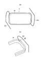
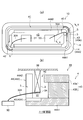
- FIG. 1 is an explanatory view showing a characteristic part of a speaker device according to an embodiment of the present invention.
- the speaker device 1 includes a diaphragm 2, a voice coil 3, a magnetic circuit 4, and a stationary part (not shown).
- the diaphragm 2 is supported by a stationary part (not shown).
- the stationary portion is a portion that is relatively stationary with respect to the vibration caused by the driving of the voice coil 3, and does not indicate that it is completely stationary.
- the frame of the speaker device 1, the magnetic circuit 4 itself or a part thereof, or the mounting location where the speaker device 1 is mounted becomes a stationary portion.
- the speaker device 1 has a structure in which a yoke constituting a magnetic circuit described later supports the diaphragm 2.
- the speaker 2 is arranged on the outer periphery of the yoke. The outer periphery is supported.
- the voice coil 3 has one end joined directly or indirectly to the diaphragm 2. As shown in the figure, one end surface 3B on the sound radiation direction SD side of the voice coil 3 may be directly joined to the diaphragm 2, or the voice coil 3 is joined to the diaphragm 2 via a support portion such as a voice coil bobbin. May be. When joining via a support part such as a voice coil bobbin, the support part may be held on the stationary part by holding means such as a damper.
- the magnetic circuit 4 forms a magnetic gap 4G in which the voice coil 3 is disposed, and is supported by a stationary part (not shown) or the magnetic circuit 4 itself becomes a stationary part.
- the magnetic circuit 4 includes components such as a yoke, a magnet, and a plate.
- the magnetic gap 4G is configured using a plate.
- an inner magnet type or an outer magnet type magnetic circuit may be employed using a magnet magnetized in a direction substantially perpendicular to the acoustic radiation direction SD.
- the magnetic gap 4G is constituted by the yoke and the magnet. You may employ
- a magnet or a plate may be supported by a frame (non-magnetic material) described later if necessary.
- the frame supports the magnet or the plate
- the frame has a bottom surface facing the end surface of the voice coil 3 and becomes a stationary portion.
- a repulsive magnetic circuit (a magnet is arranged inside or outside the voice coil 3) in which a frame and a plurality of magnets that sandwich the plate are supported by a frame may be used.
- the lead wire 30A of the voice coil 3 has a lead portion 30 that is drawn across the end surface 3A opposite to the diaphragm 2 side of the voice coil 3. .
- a pair of ends thereof are connected to the lead wire 30A.
- the voice coil 3 formed by winding one conductive wire can form a lead wire 30A by extending portions at both ends of the conductive wire.
- the voice coil 30A is not pulled out from the end of the voice coil 3 on the diaphragm 2 side, but rather from the end of the voice coil 3 on the diaphragm 2 side on the opposite side of the acoustic radiation direction SD. 3, and more specifically, is pulled out from the end opposite to the diaphragm 2 (the opposite side of the acoustic radiation direction SD).
- both of the pair of signal input terminals are on one side of the voice coil 3
- one of the pair of lead wires 30A inevitably crosses the end face 3A of the voice coil 3, and is drawn onto the end face 3A. Part 30 is formed.
- the lead wire 30 ⁇ / b> A has a side surface of the voice coil 3 opposite to the side where the signal input terminal is arranged, that is, the signal input terminal is outside the voice coil 3.
- the signal input terminal is outside the voice coil 3.
- the magnetic circuit 4 has a bottom surface 4A facing the end surface 3A of the voice coil 3 disposed in the magnetic gap 4G, and the bottom surface 4A has a voice coil on the bottom surface 4A.
- a retracting portion 40 is formed in which the above-described drawer portion 30 is retracted when the three end surfaces 3A come into contact with or approach each other.
- the retracting portion 40 may be a recess 40A formed at a location corresponding to the drawing portion 30 of the bottom surface 4A, or as shown in FIG. 1B, the bottom surface 4A. It may be an opening 40 ⁇ / b> B formed at a location corresponding to the leading portion 30.
- the recessed portion 40A is a portion that is recessed on the opposite side to the acoustic radiation direction SD with respect to the bottom surface 4A, and the opening 40B is a portion in which an opening that penetrates the bottom of the magnetic circuit 4 is formed.
- the lead wire 30A drawn from the voice coil 3 is drawn from the end opposite to the diaphragm 2 side, the lead wire 30A interferes with the diaphragm 2. Can be suppressed. As a result, it is possible to suppress the generation of abnormal noise and the deterioration of the vibration characteristics of the diaphragm 2 due to the contact between the diaphragm 2 and the lead wire 30A.
- a speaker device used for a portable information device such as a mobile phone is highly demanded to be small and thin, and a diaphragm (diaphragm) is often a lightweight and thin one.
- the lead wire 30 ⁇ / b> A drawn out from the voice coil 3 is drawn out from the end opposite to the diaphragm 2 side, so that the end surface 3 ⁇ / b> B on the diaphragm side of the voice coil 3 is used as the diaphragm 2. It can be bonded closely. As a result, the adhesive force when the voice coil 2 is directly joined to the diaphragm 2 can be strengthened, and the vibration of the voice coil 3 can be reliably transmitted to the diaphragm 2.
- the speaker device 1 since the speaker device 1 has the retracting portion 40 formed on the bottom surface 4A of the magnetic circuit 4 that is a stationary portion, the lead wire 30A is drawn from the end of the voice coil 3 opposite to the diaphragm 2 side. Even in this case, it is possible to suppress a problem that the lead wire 30A hits the bottom surface 4A of the magnetic circuit 4 and is damaged.
- the lead portion 30 is a portion where the lead wire 30 ⁇ / b> A is drawn across the end surface 3 ⁇ / b> A of the voice coil 3.
- This portion is a portion that protrudes partially toward the bottom surface 4A side from the end surface 3A of the voice coil 3, and if there is no retracting portion 40 on the bottom surface 4A, the end surface 3A of the voice coil 3 abuts against the bottom surface 4A of the magnetic circuit 4 or When approaching, the leader line 30A locally collides with the bottom surface 4A and receives a concentrated impact.
- the lead-out part 30 is accommodated in the retracting part 40, and thereby the lead-out line 30 ⁇ / b> A of the lead-out part 30. Can be prevented from receiving intensive impacts.
- a speaker device mounted on a portable electronic device such as a mobile phone is required to maintain performance against a drop impact.
- a speaker device receives a drop impact
- a small and thin speaker device with a weak supporting force such as a diaphragm (diaphragm) or a damper with respect to the weight of the voice coil
- a situation occurs where the end face collides with the bottom face of the magnetic circuit.
- the lead portion 30 is not accommodated in the retracting portion 40 and the lead wire 30A is not subjected to a large impact.
- the speaker apparatus 1 can ensure the performance maintenance with respect to a drop impact, when it mounts in a portable electronic device.
- the recess 40A that forms the retracting portion 40 preferably has a step that is equal to or larger than the outer diameter of the lead wire 30A with respect to the bottom surface 4A of the magnetic circuit 4. According to this, even when the end surface 3A of the voice coil 3 hits the bottom surface 4A of the magnetic circuit 4, all of the lead wire 30A is accommodated in the recess 40A, so that the lead wire 30A is less susceptible to impact.
- the recess 40A forming the retracting portion 40 can be formed in a shape corresponding to the region where the lead wire 30A crosses the end face 3A of the voice coil 3. According to this, the width of the recess can be limited to a necessary size, and the influence on the magnetic flux density in the magnetic circuit 4 can be reduced.
- the distance L2 from the end surface (upper surface) 4B facing the diaphragm 2 of the magnetic circuit 4 to the bottom surface 4A is made larger than the distance L1 from the diaphragm 2 to the end surface 3A of the voice coil 3 (L1 ⁇ L2).
- the diaphragm 2 comes into contact with the end face 4B of the magnetic circuit 4 before the end face 3A of the voice coil 3 hits the bottom face 4A of the magnetic circuit 4, and it is possible to reduce the impact caused by the end face 3A hitting the bottom face 4A.
- the end face 3A of the voice coil 3 may hit the bottom face 4A of the magnetic circuit 4 due to deformation of the diaphragm 2, so that the retracting portion 40 is also set when L1 ⁇ L2. It is necessary to provide.
- a distance L3 from the diaphragm 2 to the end face (upper face) 4B facing the diaphragm 2 of the magnetic circuit 4 is set as the distance L3 from the end face 3A of the voice coil 3 to the bottom face 4A of the magnetic circuit 4. May be smaller than the distance “L2 ⁇ L1” (L2 ⁇ L1 ⁇ L3), and the impact caused by the end surface 3A hitting the bottom surface 4A can be reduced. Furthermore, since the end face 3A of the voice coil 3 may hit the bottom face 4A of the magnetic circuit 4 due to deformation of the diaphragm 2, a retracting portion 40 may be provided.
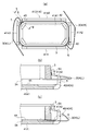
- FIG. 2 to 5 are explanatory views showing more specific features of the speaker device according to the embodiment of the present invention
- FIG. 2 is a sectional view of a main part
- FIG. 3 is a perspective view of a yoke
- FIG. 4 is a voice coil
- FIG. 5 is an explanatory diagram illustrating the function of the retracting portion).
- the magnetic circuit 4 forms a magnetic gap 4 ⁇ / b> G between a part of the first magnetic pole part 41 and a part of the second magnetic pole part 42, and the lead line is connected to the first magnetic pole part 41.
- a lead-out passage 5 through which 30A passes is formed, and a lead-out line 30A is drawn out toward the signal input terminal through the lead-out passage 5.
- the lead-out path 5 is provided on the first magnetic pole part 41 side and the lead-out line 30A is drawn outside the magnetic circuit 4, but the lead-out path is on the second magnetic pole part 42 side. 5 may be formed to draw out the lead wire 30A inside the magnetic circuit 4. In this case, an opening toward the terminal is formed inside the magnetic circuit 4.
- the extraction line 30 ⁇ / b> A can be pulled out toward the signal input terminal through the extraction path 5 without approaching the diaphragm 2.
- the lead wire 30A is pulled out from the side opposite to the diaphragm 2 side of the voice coil 3, it is possible to more reliably suppress problems caused by interference between the lead wire 30A and the diaphragm 2.
- the speaker device 1A includes a frame 10 as a stationary part, and the diaphragm 2 includes a central vibrating part 2A and an edge part 2B formed on the outer side and supported by the frame 10 whose outer peripheral part is a stationary part. It has.
- the central vibration part 2A and the edge part 2B may be integrated or separate.
- a reinforcing member 11 having higher rigidity than that of the central vibrating portion 2A is attached to the central vibrating portion 2A as necessary, and an outer peripheral portion thereof extends beyond the outer edge portion of the second magnetic pole portion 42, and the voice coil 3 up.
- the outer peripheral portion of the reinforcing member 11 may extend in the vicinity of the inner edge portion of the voice coil 3, or in the vicinity of the outer edge portion or beyond the outer edge portion.
- the reinforcing member 11 is made of, for example, polyphenylsulfone resin, and the thickness of the central vibrating portion 2A and the edge portion 2B is made thinner than that of the reinforcing member 11, and is formed of polyetherimide or a metal material. It doesn't matter.
- one end side of the voice coil 3 is joined to the outer peripheral portion of the central vibrating portion 2A, the boundary portion between the central vibrating portion 2A and the edge portion 2B, or the inner peripheral portion of the edge portion 2B.
- the lead wire 30A drawn from the voice coil 3 is drawn from the end opposite to the diaphragm 2 side, the end face 3B on the diaphragm 2 side of the voice coil 3 is brought into close contact with the diaphragm 2 and joined. can do.
- the bonding force between the diaphragm 2 and the voice coil 3 can be maintained appropriately, and the vibration of the voice coil 3 can be reliably transmitted to the diaphragm 2.
- a front cover 12 is attached to the frame 10 serving as a stationary portion so as to cover the edge portion 2B.
- the frame 10 serving as a stationary part supports the outer peripheral part of the edge part 2B and supports the magnetic circuit 4. Further, the frame 10 is provided with a signal input terminal 13 to which an end portion of the drawn lead wire 30A is connected.
- the edge portion 2B is formed in a concave shape with respect to the acoustic radiation direction SD.
- the edge portion 2B is prevented from interfering with the front cover 12, and the space required on the acoustic radiation direction SD side of the diaphragm 2 is reduced, thereby reducing the thickness of the entire speaker device 1A.
- the concave edge portion 2B becomes a part of the magnetic circuit 4 when the voice coil 3 is largely moved to the side opposite to the diaphragm 2 side. It tends to be a resistance against excessive movement of the voice coil 3 by touching.
- the voice coil joining position 2C of the diaphragm 2 and the joining position 2B1 of the edge part 2B with respect to the frame 10 (stationary part) are substantially the same height when there is no vibration.
- the front surface of the diaphragm 2 is flattened. Since the speaker device 1 ⁇ / b> A draws the lead wire 30 ⁇ / b> A from the end of the voice coil 3 opposite to the diaphragm 2 side, it is not necessary to leave a large space near the diaphragm 2. Accordingly, the speaker device 1A can be thinned or flattened, and has a structure advantageous for mounting on a small portable electronic device.
- the first magnetic pole portion 41 of the magnetic circuit 4 is formed by a yoke 41A having a bottom surface portion 41A1 and a wall portion 41A2 that rises so as to surround the outer periphery of the bottom surface portion 41A1.
- the magnetic pole portion 42 is formed of a plate 42A and a magnet 42B, and a magnetic gap 4G is formed between the inner surface of the wall portion 41A2 of the yoke 41A and the inner surface of the plate 42A.
- the magnetic gap 4G is circumferentially arranged, a first magnetic pole portion 41 (yoke 41A) is formed outside the circumferentially arranged magnetic gap 4G, and a second including a magnet 42B inside the magnetic gap 4G.
- the magnetic pole part 42 is formed.
- a lead passage 5 is formed in the first magnetic pole portion 41 (yoke 41 ⁇ / b> A), and a lead wire 30 ⁇ / b> A is drawn to the outside of the magnetic circuit 4 through the lead passage 5.
- the drawer passage 5 is formed continuously with the retracting portion 40.
- the first magnetic pole portion 41 (yoke 41A) has a plurality of corner portions, and the retracting portion 40 and the extraction passage 5 are formed in the vicinity of the corner portions.
- the retracting portion 40 is formed on the bottom surface portion 41A1 of the yoke 41A, and is formed so that the width of the retracting portion 40 toward the drawing passage 5 is gradually narrowed.
- forms that can serve as the retracting portion 40 and the extraction passage 5 are formed at the four corners of the yoke 41 ⁇ / b> A. In practice, two of them, preferably two on the diagonal line, are selected and the retracting portion 40. And used as the extraction passage 5.
- the retracting portion 40 and the lead-out passage 5 are formed only at the two corners so that the lead wire 30A can pass through, and the retracting portion 40 and the lead-out passage 5 are formed at the other two corners.
- the yoke 41A may be used.
- the retreating portion 40 has a planar shape formed in the vicinity of the corner of the magnetic circuit 4, but is not limited to this. It does not matter if it has a planar shape, as long as an area in which the drawer 30 can be retracted is secured.
- the lead-out passage 5 is formed in a discontinuous portion of the wall portion 41A2 of the yoke 41A. Further, a notch 5A is formed in the wall 41A2 at the upper end portion of the drawer passage 5, and the notch 5A is formed so that the width of the drawer passage is increased stepwise. Further, as shown in FIG. 2, a step portion 43 ⁇ / b> C is formed at the boundary portion between the wall portion 41 ⁇ / b> A ⁇ b> 2 and the bottom surface portion 41 ⁇ / b> A ⁇ b> 1 along the outer edge of the retracting portion 40 in the acoustic radiation direction SD.
- the lead wire 30A on the retracting portion 40 can be continuously extended and passed through the extraction passage 5. Accordingly, the lead wire 30A can be drawn out from the magnetic circuit 4 while avoiding large refraction of the lead wire 30A.
- the retracting portion 40 is formed on the bottom surface portion 41A1 of the yoke 41A, and the width of the retracting portion 40 toward the extraction passage 5 is gradually narrowed.
- the guide portion 5 is guided by the shape of the retracting portion 40, and the retracting portion 40 is gradually narrowed, so that the damage to the lead wire 30A can be suppressed without reducing the magnetic flux density of the magnetic gap 4G. Can do.
- a notch 5A is formed in the wall 41A2 at the upper end portion of the drawer passage 5, and the width of the drawer passage 5 is increased stepwise by the notch 5A.
- the magnetic flux is prevented from passing through the space.
- the reduction of the magnetic flux toward the magnetic gap 4G is suppressed, and a sufficient electromagnetic force acting on the voice coil 3 is ensured.
- the lead wire 30A is constituted by one lead wire constituting the voice coil 3
- the magnitude of the voice current passing through the lead wire is small, so that the electromagnetic force acting on the lead wire 3A is relatively small. Therefore, unnecessary vibration is not generated.
- the notch portion 5A formed in the wall portion 41A2 of the yoke 41A extending in the long axis direction may have a function of fixing the frame 10 to the yoke 41A when a part of the frame 10 abuts. I do not care.
- the lead-out passage 5 is formed in a discontinuous portion of the wall portion 41A2 of the yoke 41A, and the discontinuous portion is formed in a corner portion of the rectangular yoke 41A, the straight portion of the yoke 41A effective as the magnetic gap 4G. It is possible to form the extraction passage 5 with less influence on the surface.
- the stepped portion 43C directed in the acoustic radiation direction SD along the outer edge of the retracting portion 40 is formed at the boundary portion between the wall portion 41A2 and the bottom surface portion 41A1, magnetic field lines that bypass the retracting portion 40 in the yoke 41A are generated.
- the step 43C can guide the magnetic gap 4G. Thereby, the influence which the evacuation part 40 has on the magnetic gap 4G can be reduced.
- the stepped portion 43C may not be formed at the boundary portion between the wall portion 41A2 and the bottom surface portion 41A1. When the stepped portion 43C is not provided, the recess 40A or the opening that is the retracting portion 40 is continuously formed up to the wall portion 41A2.
- FIG. 4 is an explanatory diagram for explaining the leader line of the voice coil.
- FIG. 4A is a plan view of the voice coil as viewed from the direction of the diaphragm
- FIG. 4B is a perspective view of the voice coil as viewed from the direction opposite to the diaphragm.
- a diaphragm is joined to the end surface 3B shown in FIG. 5A, and a lead-out portion 30 across which the lead wire 30A crosses is formed on the end surface 3A. By pulling out the lead wire 30A from the end surface 3A side, the end surface 3B becomes flat.
- the lead-out portions of the pair of lead-out wires 30A are drawn out from positions on the diagonal lines so that the balance of the voice coil 3 can be maintained. As a result, the balance of the voice coil 3 during vibration can be maintained, and problems due to the tilt of the voice coil 3 in the magnetic gap 4G can be suppressed.
- the lead-out portion 30 By forming the lead-out portion 30 on the end surface 3A side, the lead-out portion 30 is in a state in which one lead wire 30A protrudes from the end surface, and this lead-out portion 30 is the bottom surface 4A of the magnetic circuit 4 (the bottom surface of the yoke 41A). ), The damage to one lead wire 30 increases.
- FIG. 5 is an explanatory diagram showing the function of the retracting portion 40 provided to suppress damage to the leader line 30.
- FIG. 4A is a plan view of the state in which the voice coil 3 is disposed in the magnetic gap 4G
- FIGS. 4B and 4C are cross-sectional views along the line BB.
- the drawer passage 5 is formed by opening the wall portion 41A2 that rises around the bottom surface portion 41A1 at the corner portion of the rectangular first magnetic pole portion 41 (yoke 41A).
- the retracting portion 40 is a concave portion 40A formed at a corner portion of the bottom surface portion 41A1 of the yoke 41A, and the concave portion 40A is tapered and continues to the drawer passage 5.
- the lead wire 30A drawn out from the voice coil 3 is formed by winding the conductive wire around the voice coil 3, and is formed by an extended portion of the conductive wire, and is drawn out at two locations from the inside and the outside of the voice coil. .
- the lead wire 30A is drawn from two places on the diagonal line in accordance with the corner portion of the yoke 41A.
- the lead wire 30A (R) drawn to the right is drawn from the outside of the voice coil 3 and directly led to the outside of the yoke 41A through the lead passage 5, and the lead wire 30A (L) drawn to the left is A drawing portion 30 is formed across the end surface 3A opposite to the coil vibration plate side, and is led from the retracting portion 40 to the outside of the yoke 41A through the drawing passage 5.
- the lead wire 30A is an extension of the voice coil 3
- the electromagnetic force applied to the current flowing through one lead wire 30A is negligible compared to the voice coil 3 in which the conducting wires are bundled. Therefore, even if a magnetic flux passes through the lead-out path 5, the electromagnetic force applied to the lead-out line 30A hardly affects the vibration of the voice coil 3. Also, there is almost no problem that the lead wire 30A itself vibrates and contacts the yoke 41A due to the electromagnetic force applied to the lead wire 30A.
- FIG. 5B shows a state where the end face 3A of the voice coil 3 is separated from the bottom face 4A
- FIG. 5C shows a state where the end face 3A of the voice coil 3 is in contact with the bottom face 4A.
- the lead wire 30A of the lead-out portion 30 is received in the recess 40A of the retracting portion 40 and is subject to compression or impact from the bottom surface 4A. Absent. This makes it possible to prevent the lead wire 30A from being damaged when the speaker device 1A is dropped or when the voice coil 3 has a large amplitude.
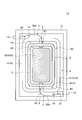
- FIG. 6 are plan views showing the entire configuration of the speaker device according to the embodiment of the present invention excluding the diaphragm.
- the speaker device 1A shown in FIG. 6 includes the rectangular magnetic circuit 4 and the rectangular frame 10 as described above. The parts described above are denoted by the same reference numerals and redundant description is omitted.
- the lead wire 30 ⁇ / b> A that has passed through the lead-out passage 5 forms a surplus length Lo so as to surround the outer periphery of the magnetic circuit 4, and the surplus length Lo is erected in the frame 10.
- the end of the lead wire 30 ⁇ / b> A is connected to connection terminals 50 and 51 in the frame 10 connected to the signal input terminal 13.
- the extra length support part 14 does not need to be provided in the flame
- the speaker apparatus 1B shown in FIG. 7 includes the rectangular magnetic circuit 4 and the rectangular frame 10 as described above.
- the parts described above are denoted by the same reference numerals and redundant description is omitted.
- the first magnetic pole portion 41 (yoke 41A) has a straight portion, and a retracting portion 40 and a drawer passage 5 are formed in the vicinity of an intermediate portion of the straight portion.
- the lead wire 30 ⁇ / b> A that has passed through the lead-out passage 5 forms a surplus length portion Lo so as to surround the outer periphery of the magnetic circuit 4, and the surplus length portion Lo is erected in the frame 10.
- the end of the lead wire 30 ⁇ / b> A is connected to the connection terminals 50 and 51 in the frame 10 connected to the signal input terminal 13.
- the extra length support part 14 does not need to be provided in the flame
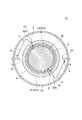
- the speaker device 1 ⁇ / b> C the first magnetic pole portion 41 (yoke 41 ⁇ / b> A) has a curved portion, and a retracting portion 40 and a drawer passage 5 are formed in the vicinity of an intermediate portion of the curved portion.
- the lead wire 30 ⁇ / b> A that has passed through the lead-out passage 5 forms a surplus length portion Lo so as to surround the outer periphery of the circular magnetic circuit 4, and the surplus length portion Lo is erected in the frame 10.
- the end of the lead wire 30 ⁇ / b> A is connected to connection terminals 50 and 51 in the frame 10 connected to the signal input terminal 13.
- the extra length support part 14 does not need to be provided in the flame
- FIG. 9 is an explanatory view showing a speaker device according to another embodiment of the present invention.
- the magnetic gap 4G is arranged circumferentially, the first magnetic pole portion 43 including the magnet 43B is formed outside the circumferentially arranged magnetic gap 4G, and the central opening is formed inside the magnetic gap 4G.
- a second magnetic pole portion 44 having 45 is formed, a lead-out passage 5 is formed in the second magnetic pole portion 44, and a lead wire 30 ⁇ / b> A is drawn out to the central opening 45 through the lead-out passage 5.
- the first magnetic pole portion 43 positioned outside the magnetic gap 4G includes a plate 43A and a magnet 43B, and the second magnetic pole portion 44 positioned inside the magnetic gap 4G includes a bottom portion 44A1, a wall portion 44A2, and a central opening 45.
- a drawer passage 5 is formed in a discontinuous portion of the wall portion 44A2 of the yoke 44A, and a retracting portion 40 (concave portion 40A) continuous with the drawer passage 5 is formed in the bottom portion 44A1.
- the speaker device 1D provided with such an external magnetic type magnetic circuit 4 also has the same function as the speaker devices 1, 1A, 1B, 1C described above.
- FIG. 6 to 8 show a so-called inner magnet type magnetic circuit
- FIG. 9 shows a so-called outer magnet type magnetic circuit.
- the present invention is not limited to this.
- a double magnet type magnetic circuit is shown. 6 to 8, an annular outer magnet and an outer plate surrounding the magnet 42B and the plate 42A are arranged on the bottom surface portion 41A1 or the wall portion 41A2 of the yoke 41A, and the outer plate and the plate 42A are disposed.
- a magnetic gap 4G is formed between the two.
- the magnetic circuit 4 may be an internal magnetic type, an external magnetic type, or a double magnetic type magnetic circuit, and the yokes 41A and 44A may be so-called frames (non-magnetic materials). Further, when the magnetic circuit 4 is a repulsive magnetic circuit, two magnets (same magnetic poles facing each other) sandwiching the plate 42A are arranged in FIGS. 6 to 8, and the plate 43A is sandwiched in FIG. Two magnets (the magnetic poles facing each other) may be arranged.
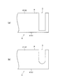
- FIG. 10 is an explanatory view showing an example of forming the extraction passage.
- FIG. 4A is a side view showing one example of forming the extraction passage 5
- FIG. 4B is a side view showing another formation of the extraction passage 5.
- the lead-out passage 5 formed in the magnetic circuit 4 is notched linearly from the upper end a of the wall 41A2 of the yoke 41A to the bottom 41A1, as shown in FIG.
- the end portion of the wall 41A2 of the yoke 41A is linearly cut from the upper end portion a toward the bottom surface portion 41A1 by a predetermined distance to form a curved end. You may form in the notched state.
- FIG. 11 is an explanatory diagram showing an example of how to draw out the leader line from the voice coil.
- 4A is a plan view of the voice coil 3
- FIG. 4B is an enlarged view of the vicinity of the winding start position of the conducting wire 30A of the voice coil 3 shown in FIG. 1A
- FIG. It is an enlarged view of the vicinity of the winding end position of the conducting wire 30A of the voice coil 3 shown in FIG.
- FIGS. 4D and 6E are explanatory views showing modifications of the voice coil shown in FIGS. 2B and 2C, respectively.
- the voice coil 3 is defined so that a pair of lead lines 30A is substantially point-symmetric with respect to the center point O of the voice coil 3.
- the lead wire 30A has a center of gravity CG of the voice coil 3 resulting from the conducting wire 31 from the start of winding of the voice coil 3 to the end of winding, and is located at a different position with respect to the center position O.
- the shape of the leader line 30A is defined so that it can be taken.
- the pair of lead lines 30A are arranged at substantially point-symmetrical positions so that the weight balance of the voice coil 3 can be ensured as much as possible when only the pair of lead lines 30A is watched.
- the voice coil 3 starts winding from the winding start position 31S in the vicinity of the rectangular corner, and is wound a predetermined number of times (N times). The winding ends at the winding end position 31E in the vicinity of the opposing parts.
- the center of gravity CG is deviated from the center position of the voice coil by the amount of the conductor 31 from the winding start position 31S to the winding end position 31E. Since the center of gravity CG is deviated from the center position O of the voice coil, the shape of the leader line 31A is defined so that the voice coil 3 can be balanced.
- the center of gravity position CG of the voice coil 3 and the position of the bent portion 30A1 of the lead wire 30A are defined to be opposite to each other across the diagonal line DL passing through the voice coil center point O. ing.
- the shape of the bent portion 30A1 of the pair of lead wires 30A is defined so that the voice coil 3 can be balanced in consideration of the line density of the lead wires 30A.
- FIG. 12 is an explanatory view showing a speaker device according to another embodiment of the present invention.
- the parts described above are denoted by the same reference numerals and redundant description is omitted.
- the speaker device 1E is an explanatory view showing a multifunctional speaker. This embodiment shows that the above-described speaker device can be similarly applied to a multi-function speaker device.
- the external shape of the speaker device shown in the figure is a circular shape, but it may be a track shape, an elliptical shape, a rectangular shape, a polygonal shape, a rectangular shape, or the like, and is not particularly limited.
- the magnetic circuit 4 vibrates between the voice coil 3 and the magnetic circuit 4 on the principle of action / reaction.
- the entire speaker device 1E vibrates and is transmitted to a user who uses an electronic device equipped with the speaker device 1E, for example, a mobile phone device, and informs the user that there is an incoming call. be able to.
- the diaphragm 2 when an electric signal is input to the voice coil 3, the diaphragm 2 also vibrates, so that a sound wave is emitted, and a reproduced sound can be provided to the user.
- Whether to generate sound waves by vibrating the diaphragm 2 or to transmit the vibration to the user by vibrating the magnetic circuit 4 can be switched according to the frequency of the electric signal input to the voice coil 3.
- Such a speaker device 1E includes the frame 10, the diaphragm 2 supported by the frame 10, the magnetic circuit 4, and the voice coil 3 supported by the diaphragm 2, as in the above-described embodiment. Further, the magnetic circuit 4 is supported by the frame 10 via the damper 50 so as to be supported by the frame 10 so as to freely vibrate.
- the damper 50 is formed of a rigid member that can support the magnetic circuit 4 in a freely vibrating manner, such as a metal material. Further, if necessary, a weight may be attached to the magnetic circuit 4 to adjust the resonance frequency of the magnetic circuit 4.
- a vent hole 51 communicating with the outside is formed in the bottom surface portion of the frame 10 facing the magnetic circuit 4 to prevent the magnetic circuit 4 from vibrating due to air resistance, and the temperature of the magnetic circuit 4 is reduced. This makes it possible to prevent the temperature from becoming high.
- a concave portion which is a retracting portion 40 is formed on the bottom surface portion 41A1 of the yoke 41A provided in the magnetic circuit 4 facing the lower end portion of the voice coil 3. Similar to the above-described embodiment, the retracting portion 40 may be formed as a recess or an opening.
- the magnetic circuit 4 and the frame 10 when transmitting vibration to the user, vibrate. However, when functioning as a speaker device (when sound is generated), vibration is generated. Since the magnetic circuit 4 and the frame 10 are relatively stationary with respect to the plate 2 and the voice coil 3, the magnetic circuit 4 and the frame 10 are still stationary portions.
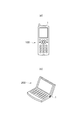
- FIG. 13 is an explanatory view showing an electronic apparatus including the speaker device according to the embodiment of the present invention.
- An electronic device 100 such as a mobile phone shown in FIG. 1A or an electronic device 200 such as a portable information terminal (mobile PC) shown in FIG. 1B is a speaker device according to an embodiment of the present invention.
Landscapes
- Physics & Mathematics (AREA)
- Engineering & Computer Science (AREA)
- Acoustics & Sound (AREA)
- Signal Processing (AREA)
- Audible-Bandwidth Dynamoelectric Transducers Other Than Pickups (AREA)
- Diaphragms For Electromechanical Transducers (AREA)
Abstract
Description
[請求項1]静止部と、該静止部に支持される振動板と、一端側が前記振動板に直接又は間接的に接合されるボイスコイルと、該ボイスコイルが配置される磁気ギャップを形成して前記静止部に支持されるか又は前記静止部となる磁気回路とを備え、前記ボイスコイルの引出線が当該ボイスコイルの前記振動板側とは逆側の端面を横切って引き出される引出部を有し、前記磁気回路は前記磁気ギャップに配置される前記ボイスコイルの端面に対面する底面を有し、該底面には、当該底面に前記ボイスコイルの端面が当接又は近接したときに前記引出部が退避する退避部が形成されていることを特徴とするスピーカ装置。
Claims (22)
- 静止部と、該静止部に支持される振動板と、一端側が前記振動板に直接又は間接的に接合されるボイスコイルと、該ボイスコイルが配置される磁気ギャップを形成して前記静止部に支持されるか又は前記静止部となる磁気回路とを備え、
前記ボイスコイルの引出線が当該ボイスコイルの前記振動板側とは逆側の端面を横切って引き出される引出部を有し、
前記磁気回路は前記磁気ギャップに配置される前記ボイスコイルの端面に対面する底面を有し、
該底面には、当該底面に前記ボイスコイルの端面が当接又は近接したときに前記引出部が退避する退避部が形成されていることを特徴とするスピーカ装置。 - 前記退避部は、前記底面の前記引出部に対応する箇所に形成される凹部であることを特徴とする請求項1に記載のスピーカ装置。
- 前記凹部は、前記底面に対して前記引出線の外径に等しいか又はそれより大きい段差を有することを特徴とする請求項2に記載のスピーカ装置。
- 前記凹部は、前記ボイスコイルの端面を前記引出線が横切る領域に応じた形状に形成されることを特徴とする請求項3記載のスピーカ装置。
- 前記磁気回路の前記振動板に対面する端面から前記底面までの距離が前記振動板から前記ボイスコイルの端面までの距離より大きいことを特徴とする請求項4記載のスピーカ装置。
- 前記磁気回路は、第1の磁極部の一部と第2の磁極部の一部との間に前記磁気ギャップを形成し、
前記第1の磁極部又は前記第2の磁極部の一方に前記引出線が通過する引出通路が形成され、
前記引出線は前記引出通路を通って引き出されることを特徴とする請求項5に記載のスピーカ装置。 - 前記引出通路は、前記退避部に連続して形成されていることを特徴とする請求項6記載のスピーカ装置。
- 前記磁気ギャップは周状に配置され、
周状に配置された前記磁気ギャップの外側に前記第1の磁極部が形成され、前記磁気ギャップの内側に磁石を含む前記第2の磁極部が形成され、
前記第1の磁極部に前記引出通路が形成され、当該引出通路を通って前記引出線が磁気回路の外側に引き出されることを特徴とする請求項7に記載のスピーカ装置。 - 前記第1の磁極部は複数の角部を有し、
前記退避部と前記引出通路は、前記角部の近傍に形成されていることを特徴とする請求項8に記載のスピーカ装置。 - 前記第1の磁極部は、底面部と当該底面部の外周を囲むように立ち上がる壁部を有するヨークで形成され、
前記ヨークの底面部に前記退避部が形成され、前記引出通路に向かう前記退避部の幅が徐々に狭くなることを特徴とする請求項9記載のスピーカ装置。 - 前記壁部の不連続部分に前記引出通路が形成され、該引出通路の上端部分で前記壁部に切り欠き部が形成され、該切り欠き部によって前記引出通路の幅が段階的に大きくなることを特徴とする請求項10記載のスピーカ装置。
- 前記壁部と前記底面部の境界部分に前記退避部の外縁に沿って音響放射方向に向けた段部を形成することを特徴とする請求項11記載のスピーカ装置。
- 前記振動板は、中央振動板とその外側に形成されて外周部が前記静止部に支持されるエッジ部とを備え、
前記中央振動板には、当該中央振動板より剛性の高い補強部材が取り付けられることを特徴とする請求項12に記載のスピーカ装置。 - 前記中央振動板の外周部分又は前記中央振動板と前記エッジ部の境界部分又は前記エッジ部の内周部に前記ボイスコイルの一端側が接合されていることを特徴とする請求項13記載のスピーカ装置。
- 前記エッジ部は音響放射方向に対して凹状に形成されることを特徴とする請求項14記載のスピーカ装置。
- 非振動時に前記振動板のボイスコイル接合位置と前記エッジ部の前記静止部に対する接合位置とが略同じ高さにあることを特徴とする請求項15記載のスピーカ装置。
- 前記ボイスコイルは1つの導線が巻かれることで形成され、前記引出線は前記導線の延長部分によって形成されることを特徴とする請求項1記載のスピーカ装置。
- 前記退避部は、前記底面の前記引出線に対応する箇所に形成される開口部であることを特徴とする請求項1に記載のスピーカ装置。
- 前記第1の磁極部は複数の直線部又は曲線部を有し、
前記退避部と前記引出通路は、前記直線部又は曲線部の中間部分の近傍に形成されていることを特徴とする請求項8に記載のスピーカ装置。 - 前記磁気ギャップは周状に配置され、
周状に配置された前記磁気ギャップの外側に磁石を含む前記第1の磁極部が形成され、前記磁気ギャップの内側に中央開口部を有する第2の磁極部が形成され、
前記第2の磁極部に前記引出通路が形成され、当該引出通路を通って前記引出線が前記中央開口部に引き出されることを特徴とする請求項6に記載のスピーカ装置。 - 前記引出線は前記引出通路を通過して前記磁気回路の周囲に余長部を形成することを特徴とする請求項6記載のスピーカ装置。
- 請求項1に記載のスピーカ装置を備えることを特徴とする電子機器。
Priority Applications (3)
| Application Number | Priority Date | Filing Date | Title |
|---|---|---|---|
| CN200980155629.0A CN102308595B (zh) | 2009-01-30 | 2009-01-30 | 扬声器装置 |
| PCT/JP2009/051646 WO2010087007A1 (ja) | 2009-01-30 | 2009-01-30 | スピーカ装置 |
| JP2010548335A JP5026600B2 (ja) | 2009-01-30 | 2009-01-30 | スピーカ装置 |
Applications Claiming Priority (1)
| Application Number | Priority Date | Filing Date | Title |
|---|---|---|---|
| PCT/JP2009/051646 WO2010087007A1 (ja) | 2009-01-30 | 2009-01-30 | スピーカ装置 |
Publications (1)
| Publication Number | Publication Date |
|---|---|
| WO2010087007A1 true WO2010087007A1 (ja) | 2010-08-05 |
Family
ID=42395277
Family Applications (1)
| Application Number | Title | Priority Date | Filing Date |
|---|---|---|---|
| PCT/JP2009/051646 Ceased WO2010087007A1 (ja) | 2009-01-30 | 2009-01-30 | スピーカ装置 |
Country Status (3)
| Country | Link |
|---|---|
| JP (1) | JP5026600B2 (ja) |
| CN (1) | CN102308595B (ja) |
| WO (1) | WO2010087007A1 (ja) |
Cited By (5)
| Publication number | Priority date | Publication date | Assignee | Title |
|---|---|---|---|---|
| JP2020129821A (ja) * | 2020-04-27 | 2020-08-27 | 東北パイオニア株式会社 | スピーカ装置 |
| JP2022009924A (ja) * | 2020-04-27 | 2022-01-14 | 東北パイオニア株式会社 | スピーカ装置 |
| WO2022153602A1 (ja) * | 2021-01-14 | 2022-07-21 | 株式会社村田製作所 | リニア振動モータ及び電子機器 |
| JP2023055986A (ja) * | 2021-11-02 | 2023-04-18 | 東北パイオニア株式会社 | スピーカ装置 |
| EP4708918A3 (en) * | 2023-12-20 | 2026-03-25 | Shenzhen Shokz Co., Ltd. | Diaphragm, air conduction speaker, and wearable electronic device |
Families Citing this family (3)
| Publication number | Priority date | Publication date | Assignee | Title |
|---|---|---|---|---|
| JP6698751B2 (ja) * | 2018-06-19 | 2020-05-27 | 東北パイオニア株式会社 | スピーカ装置 |
| EP4287650A4 (en) | 2021-02-01 | 2024-08-07 | Samsung Electronics Co., Ltd. | SPEAKER HAVING IMPROVED BL CHARACTERISTICS AND ELECTRONIC DEVICE COMPRISING SAME |
| CN115175069A (zh) * | 2022-07-06 | 2022-10-11 | 美律电子(深圳)有限公司 | 动圈式扬声器 |
Citations (3)
| Publication number | Priority date | Publication date | Assignee | Title |
|---|---|---|---|---|
| JPS57151096U (ja) * | 1981-03-17 | 1982-09-22 | ||
| JP2003037895A (ja) * | 2001-07-26 | 2003-02-07 | Matsushita Electric Ind Co Ltd | スピーカ |
| JP2003521184A (ja) * | 2000-01-27 | 2003-07-08 | コーニンクレッカ フィリップス エレクトロニクス エヌ ヴィ | 可動コイル及び可動コイルの接続リード線用の弾性保持要素を有する電気音響変換器 |
Family Cites Families (4)
| Publication number | Priority date | Publication date | Assignee | Title |
|---|---|---|---|---|
| CN2265654Y (zh) * | 1996-02-06 | 1997-10-22 | 李井海 | 双驱动扬声器 |
| JP2004096670A (ja) * | 2002-09-04 | 2004-03-25 | Matsushita Electric Ind Co Ltd | スピーカ |
| CN201025732Y (zh) * | 2007-03-09 | 2008-02-20 | 富港电子(东莞)有限公司 | 扬声器 |
| CN101400010B (zh) * | 2007-09-29 | 2012-03-21 | 马钧 | 一种新型音频转换器 |
-
2009
- 2009-01-30 JP JP2010548335A patent/JP5026600B2/ja active Active
- 2009-01-30 CN CN200980155629.0A patent/CN102308595B/zh active Active
- 2009-01-30 WO PCT/JP2009/051646 patent/WO2010087007A1/ja not_active Ceased
Patent Citations (3)
| Publication number | Priority date | Publication date | Assignee | Title |
|---|---|---|---|---|
| JPS57151096U (ja) * | 1981-03-17 | 1982-09-22 | ||
| JP2003521184A (ja) * | 2000-01-27 | 2003-07-08 | コーニンクレッカ フィリップス エレクトロニクス エヌ ヴィ | 可動コイル及び可動コイルの接続リード線用の弾性保持要素を有する電気音響変換器 |
| JP2003037895A (ja) * | 2001-07-26 | 2003-02-07 | Matsushita Electric Ind Co Ltd | スピーカ |
Cited By (6)
| Publication number | Priority date | Publication date | Assignee | Title |
|---|---|---|---|---|
| JP2020129821A (ja) * | 2020-04-27 | 2020-08-27 | 東北パイオニア株式会社 | スピーカ装置 |
| JP2022009924A (ja) * | 2020-04-27 | 2022-01-14 | 東北パイオニア株式会社 | スピーカ装置 |
| WO2022153602A1 (ja) * | 2021-01-14 | 2022-07-21 | 株式会社村田製作所 | リニア振動モータ及び電子機器 |
| JP2023055986A (ja) * | 2021-11-02 | 2023-04-18 | 東北パイオニア株式会社 | スピーカ装置 |
| JP2025066811A (ja) * | 2021-11-02 | 2025-04-23 | 東北パイオニア株式会社 | スピーカ装置 |
| EP4708918A3 (en) * | 2023-12-20 | 2026-03-25 | Shenzhen Shokz Co., Ltd. | Diaphragm, air conduction speaker, and wearable electronic device |
Also Published As
| Publication number | Publication date |
|---|---|
| CN102308595A (zh) | 2012-01-04 |
| JP5026600B2 (ja) | 2012-09-12 |
| JPWO2010087007A1 (ja) | 2012-07-26 |
| CN102308595B (zh) | 2014-12-17 |
Similar Documents
| Publication | Publication Date | Title |
|---|---|---|
| US20240022845A1 (en) | Speaker device | |
| JP5026600B2 (ja) | スピーカ装置 | |
| US8027502B2 (en) | Speaker device and mobile phone | |
| US8135160B2 (en) | Speaker device and mobile phone | |
| US11950071B2 (en) | Acoustic device | |
| US9185494B2 (en) | Inner magnet type microspeaker | |
| JP5494494B2 (ja) | スピーカユニットおよび携帯情報端末 | |
| JP4603972B2 (ja) | スピーカー装置用振動板及びスピーカー装置並びに携帯電話機 | |
| JP5676580B2 (ja) | スピーカ、及びそのスピーカを備える音響機器 | |
| KR100888965B1 (ko) | 스피커 | |
| KR101148833B1 (ko) | 음향변환장치 | |
| CN109275075B (zh) | 发声器件 | |
| TW201129122A (en) | Multi-function micro-speaker | |
| JPWO2008136090A1 (ja) | スピーカー装置 | |
| US10764685B2 (en) | Speaker | |
| CN104320746B (zh) | 扬声器装置 | |
| JP4796153B2 (ja) | 振動板及びスピーカー装置 | |
| KR20050075788A (ko) | 스피커 | |
| CN104320743B (zh) | 小型扬声器装置 | |
| JP2012080209A (ja) | 振動板、スピーカユニットおよび携帯情報端末 | |
| JP2004241967A (ja) | スピーカ | |
| CN104581561A (zh) | 小型扬声器装置 |
Legal Events
| Date | Code | Title | Description |
|---|---|---|---|
| WWE | Wipo information: entry into national phase |
Ref document number: 200980155629.0 Country of ref document: CN |
|
| 121 | Ep: the epo has been informed by wipo that ep was designated in this application |
Ref document number: 09839197 Country of ref document: EP Kind code of ref document: A1 |
|
| WWE | Wipo information: entry into national phase |
Ref document number: 2010548335 Country of ref document: JP |
|
| NENP | Non-entry into the national phase |
Ref country code: DE |
|
| 122 | Ep: pct application non-entry in european phase |
Ref document number: 09839197 Country of ref document: EP Kind code of ref document: A1 |