WO2010084965A1 - 補正レンズ駆動用ボイスコイルモータ、手振れ補正装置、交換レンズ及び光学機器 - Google Patents
補正レンズ駆動用ボイスコイルモータ、手振れ補正装置、交換レンズ及び光学機器 Download PDFInfo
- Publication number
- WO2010084965A1 WO2010084965A1 PCT/JP2010/050832 JP2010050832W WO2010084965A1 WO 2010084965 A1 WO2010084965 A1 WO 2010084965A1 JP 2010050832 W JP2010050832 W JP 2010050832W WO 2010084965 A1 WO2010084965 A1 WO 2010084965A1
- Authority
- WO
- WIPO (PCT)
- Prior art keywords
- correction lens
- voice coil
- coil motor
- permanent magnet
- magnetic
- Prior art date
- Legal status (The legal status is an assumption and is not a legal conclusion. Google has not performed a legal analysis and makes no representation as to the accuracy of the status listed.)
- Ceased
Links
Images




Classifications
-
- G—PHYSICS
- G02—OPTICS
- G02B—OPTICAL ELEMENTS, SYSTEMS OR APPARATUS
- G02B27/00—Optical systems or apparatus not provided for by any of the groups G02B1/00 - G02B26/00, G02B30/00
- G02B27/64—Imaging systems using optical elements for stabilisation of the lateral and angular position of the image
- G02B27/646—Imaging systems using optical elements for stabilisation of the lateral and angular position of the image compensating for small deviations, e.g. due to vibration or shake
-
- G—PHYSICS
- G03—PHOTOGRAPHY; CINEMATOGRAPHY; ANALOGOUS TECHNIQUES USING WAVES OTHER THAN OPTICAL WAVES; ELECTROGRAPHY; HOLOGRAPHY
- G03B—APPARATUS OR ARRANGEMENTS FOR TAKING PHOTOGRAPHS OR FOR PROJECTING OR VIEWING THEM; APPARATUS OR ARRANGEMENTS EMPLOYING ANALOGOUS TECHNIQUES USING WAVES OTHER THAN OPTICAL WAVES; ACCESSORIES THEREFOR
- G03B5/00—Adjustment of optical system relative to image or object surface other than for focusing
-
- G—PHYSICS
- G02—OPTICS
- G02B—OPTICAL ELEMENTS, SYSTEMS OR APPARATUS
- G02B7/00—Mountings, adjusting means, or light-tight connections, for optical elements
- G02B7/02—Mountings, adjusting means, or light-tight connections, for optical elements for lenses
-
- G—PHYSICS
- G03—PHOTOGRAPHY; CINEMATOGRAPHY; ANALOGOUS TECHNIQUES USING WAVES OTHER THAN OPTICAL WAVES; ELECTROGRAPHY; HOLOGRAPHY
- G03B—APPARATUS OR ARRANGEMENTS FOR TAKING PHOTOGRAPHS OR FOR PROJECTING OR VIEWING THEM; APPARATUS OR ARRANGEMENTS EMPLOYING ANALOGOUS TECHNIQUES USING WAVES OTHER THAN OPTICAL WAVES; ACCESSORIES THEREFOR
- G03B5/00—Adjustment of optical system relative to image or object surface other than for focusing
- G03B5/02—Lateral adjustment of lens
-
- H—ELECTRICITY
- H04—ELECTRIC COMMUNICATION TECHNIQUE
- H04N—PICTORIAL COMMUNICATION, e.g. TELEVISION
- H04N23/00—Cameras or camera modules comprising electronic image sensors; Control thereof
- H04N23/60—Control of cameras or camera modules
- H04N23/68—Control of cameras or camera modules for stable pick-up of the scene, e.g. compensating for camera body vibrations
- H04N23/682—Vibration or motion blur correction
- H04N23/685—Vibration or motion blur correction performed by mechanical compensation
- H04N23/687—Vibration or motion blur correction performed by mechanical compensation by shifting the lens or sensor position
-
- G—PHYSICS
- G02—OPTICS
- G02B—OPTICAL ELEMENTS, SYSTEMS OR APPARATUS
- G02B27/00—Optical systems or apparatus not provided for by any of the groups G02B1/00 - G02B26/00, G02B30/00
- G02B27/64—Imaging systems using optical elements for stabilisation of the lateral and angular position of the image
Definitions
- the present invention relates to a voice coil motor that drives a lens that corrects image blur caused by camera shake or the like in an optical device such as a camera or binoculars, a camera shake correction device that is operated by the voice coil motor, and an interchangeable lens equipped with the camera shake correction device.
- an optical device such as a camera or binoculars
- a camera shake correction device that is operated by the voice coil motor
- an interchangeable lens equipped with the camera shake correction device relates to an optical device.
- the camera shake correction device is a device that detects camera shake at the time of shooting and moves an image forming position on an image sensor such as a CCD to an original position in accordance with the detected vibration.
- the image stabilization device mainly employs an image sensor shift method (for example, a CCD shift method) or a lens shift method.
- the image sensor shift method is a method for correcting image blur by shifting the image sensor (CCD) based on camera shake vibration detected by a vibration detection sensor such as a gyro sensor.
- the lens shift method is based on the vibration detected by the vibration detection sensor. ), And the image blur is corrected by changing the refraction of light.
- the terms “camera shake” and “image blur” are often used interchangeably, but only the term “camera shake” is used here to prevent confusion.
- the image stabilization by the image sensor shift method is advantageous for downsizing compared to the lens shift method because it is not necessary to shift the optical system, and is mainly used in a compact (portable) digital camera.
- camera shake correction by the lens shift method is excellent in a camera shake prevention function, but is disadvantageous for miniaturization, and is therefore mainly used for interchangeable lenses and digital video cameras of digital single lens reflex cameras.
- the lens shift method can completely prevent camera shake theoretically, it is necessary to control the movement of the correction lens with high accuracy on a plane orthogonal to the optical axis of the imaging lens.
- the power consumption of digital cameras, etc. is not constant and increases temporarily when shooting (shutter is released) or when data is written to a memory card. Then, a sudden voltage drop occurs, and the battery voltage may fall below the camera drive voltage. For this reason, it is preferable that the current supplied to the correction lens driving means (for example, the voice coil motor) is not increased when the camera shake correction operation is performed.
- the correction lens driving means for example, the voice coil motor
- the camera shake correction apparatus using the lens shift system includes a voice coil motor (VCM) having a magnetic circuit unit including a permanent magnet and a yoke and a movable coil fixed to a holding frame of the correction lens as a driving unit for the correction lens.
- VCM voice coil motor
- Patent No. 4,181,663 has a pair of polarized regions via neutral regions 13f1 and 13f2 that are not magnetized, as shown in FIG. 9 (a).
- VCM includes the width of the hollow portion of the air-core coil 12, the width of the neutral regions 13f1 and 13f2 of the permanent magnets 13c and 13d, and the maximum movement amount Sc in one direction of the air-core coil 12.
- the maximum thrust is generated when the amount of movement of the correction lens reaches the maximum Sc. Since this VCM has neutral regions 13f1 and 13f2 that are not magnetized between the opposing permanent magnets 13c and 13d, the amount of magnetic flux is reduced by the amount of the permanent magnet that contributes to generating magnetic flux in the magnetic gap. Decreases and magnetic efficiency is poor. As a result, it is necessary to pass a large current through the coil in order to obtain a predetermined thrust.
- the VCM of a camera shake correction device described in Japanese Patent No. 2641172 includes a magnetic circuit including a pair of permanent magnets arranged in parallel with a predetermined gap and a yoke that forms a magnetic gap, and a coil driven in the magnetic gap. .
- the gap between the pair of permanent magnets is not preferable from the viewpoint of magnetic efficiency, as in the neutral region not magnetized in Japanese Patent No. 4181663, and the magnetic capacity of the permanent magnet is smaller than the configuration without the gap.
- the magnetic flux density in the air gap is reduced. In order to compensate for the reduced magnetic flux density, it is necessary to increase the current flowing through the coil.
- Japanese Patent No. 26471172 does not describe the relationship between the effective conductor width of the coil, the magnetic pole width of the permanent magnet, and the longest moving distance in one side of the coil, and considers the reduction of power consumption during camera shake correction. Absent.
- the VCM of the image stabilization apparatus described in Japanese Patent Application Laid-Open No. 2008-209434 includes a pair of opposing yokes, a permanent magnet fixed to one yoke, and a magnetic gap formed by the other yoke and the permanent magnet. It consists of a driven coil.
- the permanent magnet is two-pole magnetized so that it has magnetic poles polarized in the N and S poles in the plane. Such a permanent magnet is substantially the same as that described in Japanese Patent No. 4181663 in which a neutral region that is not magnetized exists between the N pole and the S pole.
- Japanese Patent Laid-Open No. 2008-209434 does not describe the relationship between the effective conductor width of the coil, the magnetic pole width of the permanent magnet, and the longest moving distance in one side of the coil, and reduces power consumption during camera shake correction. Is not considered.
- An object of the present invention to reduce the power consumption of a voice coil motor that drives a correction lens, and to correct a lens drive voice coil motor that can generate a stable thrust even at the longest moving distance of the coil.
- An object of the present invention is to provide a camera shake correction apparatus including a motor, an interchangeable lens equipped with the camera shake correction apparatus, and an optical apparatus.
- a correction lens driving voice coil motor comprises a magnet unit having a pair of yokes and at least one permanent magnet forming a magnetic gap, and a coil disposed in the magnetic gap, and energizing the coil.
- the correction lens is driven by linearly moving the magnet unit and the coil linearly,
- the permanent magnet has magnetic poles adjacent to each other along the moving direction on the surface facing the magnetic air gap,
- the movement direction width of the permanent magnet is twice the width Wm of the magnetic pole
- the moving direction width Wa of the coil is narrower than the width 2 Wm of the permanent magnet
- the magnet unit is preferably composed of a pair of yokes and one permanent magnet fixed to the surface facing the magnetic air gap of one yoke, and the other yoke and the permanent magnet are preferably opposed to each other through the magnetic air gap. .
- the magnet unit is preferably composed of a pair of yokes and a pair of permanent magnets fixed to the opposing surfaces of the magnetic gaps of the yokes, and the opposing surfaces of the pair of permanent magnets have different magnetic poles.
- the peak value of the magnetic flux density distribution in the magnetic air gap is preferably 0.5 ⁇ T or more.
- the permanent magnet is integral, and in the second aspect of the present invention, the permanent magnet is formed of a pair of block-shaped permanent magnets magnetized in the thickness direction adjacent to each other in the moving direction. Become.
- the block permanent magnets are arranged so that the magnetic poles arranged in the moving direction are different.
- the block-shaped permanent magnet is arranged so that the magnetic poles arranged in the moving direction are different and the opposing magnetic poles are also different.
- the permanent magnet is preferably a rare earth sintered magnet having a residual magnetic flux density of 1.3 ⁇ T or more.
- the constant K is preferably in the range of 1.1 to 1.5, more preferably in the range of 1.1 to 1.3.
- the magnet unit is fixed and the coil moves.
- the camera shake correction apparatus of the present invention provided in a lens barrel having an imaging lens includes a correction lens, a correction lens support frame supported in a plane orthogonal to the optical axis, and the pair of correction lens driving voice coils.
- a motor A pair of yokes constituting the magnet unit in the pair of voice coil motors are fixed in the barrel so that both coils move in a direction perpendicular to each other, The pair of coils are fixed to the correction lens support frame, The pair of coils linearly move in the magnetic gap when energized, and the correction lens supported by the correction lens support frame is driven in a plane orthogonal to the optical axis. .
- An interchangeable lens according to the present invention includes the above-described camera shake correction device, a vibration detection unit, and a camera shake correction control unit that controls the driving of the voice coil motor for driving the correction lens based on a vibration signal output from the vibration detection unit. It is characterized by.
- the interchangeable lens of the present invention includes a single focus interchangeable lens and a zoom interchangeable lens.
- An optical apparatus includes a camera shake correction device, a vibration detection unit, and a camera shake correction control unit that controls driving of the voice coil motor for driving the correction lens based on a vibration signal output from the vibration detection unit. It is characterized by being.
- the optical apparatus of the present invention includes a digital camera (for example, a lens interchangeable digital single lens reflex camera), a video camera, binoculars, a surveillance camera, an astronomical telescope, and the like.
- the correction lens driving voice coil motor uses a permanent magnet in which different magnetic poles are formed adjacent to each other without providing a substantially unneutral neutral region or gap, and the magnetic pole width of the permanent magnet is an effective conductor of the coil. Since the width (the width of the portion contributing to the generation of thrust) and the maximum relative movement distance between the magnet unit and the coil are set to satisfy predetermined conditions, the correction lens is driven out of the magnetic gap.
- the magnet unit and the coil can be moved relative to each other within a range having a magnetic flux density (for example, about 60% or more of the peak value) that generates a sufficient thrust. Therefore, power consumption during camera shake correction can be reduced, and the battery life can be extended.
- the peak value of the magnetic flux density distribution in the magnetic gap can be 0.5 T or more, and the power consumption can be further reduced.
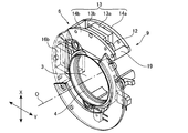
- FIG. 1 is a perspective view illustrating a configuration of a camera shake correction device for a camera including a correction lens driving voice coil motor according to the present invention.
- FIG. FIG. 2 is a perspective view showing a configuration near a first correction lens driving voice coil motor, which is a correction lens housing member that constitutes the camera shake correction apparatus shown in FIG. 1;
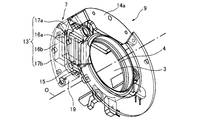
- FIG. 4 is a perspective view showing a configuration near a second correction lens driving voice coil motor, which is a correction lens housing member that constitutes the camera shake correction apparatus shown in FIG. 1;
- FIG. 3 is a partial cross-sectional front view of the correction lens storage member shown in FIG. FIG.
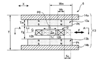
- FIG. 5 is a cross-sectional view illustrating a correction lens driving voice coil motor according to an embodiment of the present invention, in a state where an air-core coil is at a central position.
- FIG. 6 is a cross-sectional view illustrating a correction lens driving voice coil motor according to an exemplary embodiment of the present invention in a state where an air-core coil has moved to a maximum.
- FIG. 4 (a) is a cross-sectional view taken along line AA of FIG. It is a block diagram which shows an example of the control system of the camera-shake correction apparatus of this invention.
- 5 is a graph showing a magnetic flux density distribution in a magnetic gap of the magnet unit shown in FIG.
- FIG. 6 is a graph showing changes in thrust (relative value) of the correction lens driving voice coil motors of Example 1 and Comparative Example 1; It is a voice coil motor used for the conventional camera-shake correction apparatus, Comprising: It is a schematic sectional drawing which shows the state which has an air-core coil in a center position.
- FIG. 9 (a) is a schematic cross-sectional view of the voice coil motor of FIG.
- FIG. 1 shows a configuration of a camera shake correction apparatus equipped with a correction lens driving voice coil motor according to an embodiment of the present invention
- FIG. 2 shows a configuration of a correction lens support frame included in the camera shake correction apparatus.
- FIG. 4 and FIG. 5 schematically show the configuration of the correction lens driving voice coil motor.
- image stabilizer (A) Overall structure As shown in FIG. 1, an interchangeable lens provided with a camera shake correction device 1 that prevents image shake of a shot image caused by camera shake during shooting (for example, vibration having a frequency of several Hz to several tens of Hz). Has an optical system composed of a plurality of lens groups including the correction lens 3 together with the imaging lenses 10a and 10b and the focus lens (not shown). Camera shake correction device 1 supports vibration detected by the vibration detection unit (vibration detection sensor) to prevent camera shake consisting of vertical camera shake in the X direction (pitch direction) and horizontal shake in the Y direction (yaw direction). Then, the correction lens 3 is driven in the X direction and the Y direction, and the image forming position in the image sensor (CMOS or CCD) 2 is corrected when the release button is turned on.
- CMOS or CCD image stabiler
- the camera shake correction device 1 includes a frame 4 that supports the outer edge of the correction lens 3, a vibration detection unit 5X that detects vibration in the X direction of the camera, a vibration detection unit 5Y that detects vibration in the Y direction of the camera, A voice coil motor 6 for driving the first correction lens that moves the correction lens support frame 4 in the X direction, and a voice coil motor 7 for driving the second correction lens that moves the correction lens support frame 4 in the Y direction. It comprises. However, for simplicity, only the coils of the voice coil motors 6 and 7 are shown in FIG. During non-photographing, the correction lens 3 is held so as to be positioned at the center of the lens barrel 11 by a lock member (not shown).
- vibration sensors such as an angular velocity sensor (gyro sensor), an acceleration sensor, and an angle sensor can be used for the vibration detectors 5X and 5Y
- a gyro sensor is preferable in terms of responsiveness and sensitivity.
- Vibration detection direction vibration detection unit 5X and the 5Y detects, indicated by X 1 and Y 1 in FIG. 1.
- the correction lens support frame 4 includes first and second air-core coils 12 and 15 constituting first and second correction lens driving voice coil motors (also simply referred to as “voice coil motors”) 6 and 7. They are connected together.
- the camera shake correction apparatus 1 further includes position detection units 8X and 8Y that detect the position of the correction lens support frame 4.
- the position detectors 8X and 8Y for example, input infrared light emitted from the infrared light emitting diodes 18X and 18Y to a PSD (Position Sensitive Detector) through a slit (not shown) fixed to the correction lens support frame 4.
- the position of the correction lens support frame 4 is detected by utilizing the fact that the output current of the PSD changes according to the movement of the slit portion.
- the camera shake correction apparatus 1 further includes a correction lens storage member 9 integrally having a ring-shaped circuit board (not shown).
- the correction lens housing member 9 is fixed to a lens barrel 11.
- the correction lens support frame 4 is elastically supported by the correction lens housing member 9 via a coil spring at a plurality of equally spaced locations (for example, three or four locations) on the outer peripheral surface thereof.
- the correction lens support frame is formed by a plurality of minute ball-shaped roller members arranged at equal intervals along the circumferential direction between one end surface of the correction lens support frame body 4 and the flat portion fixed to the lens barrel 11.
- the body 4 can move in the X and Y directions.
- the first coil 12 and the second coil 15 are orthogonal to each other (the first coil 12 is in the X direction shown in FIG. Further, the second coil 15 moves linearly (in the Y direction), and the correction lens support frame 4 (correction lens 3) fixed to the first and second coils 12 and 15 is also corrected lens storage member 9 It moves by a minute distance in the X and Y directions against the elasticity of the coil spring provided between the two.
- the direction and magnitude of the direct current supplied to the first and second voice coil motors 6 and 7, the movement distance of the correction lens support frame 4 in the X and Y directions can be adjusted.
- the first correction lens driving voice coil motor 6 is a moving coil type voice coil motor (linear actuator), which reciprocates in the X direction.
- the pair of permanent magnets 13a and 13b form a magnetic gap in which the first coil 12 is disposed.
- the pair of yokes 14a and 14b is made of a ferromagnetic material (for example, steel) and is fixed to the correction lens storage member 9 at a predetermined position in the lens barrel 11.
- the first voice coil motor 6 has a structure in which the first coil 12 is arranged along the center line Lc in the magnetic gap G formed between the pair of opposed permanent magnets 13a and 13b. Have. As shown in FIG. 3, the first coil 12 is fixed to the correction lens support frame 4 via a connecting member 6b.
- the pair of yokes 14a and 14b are connected by a spacer 19 made of, for example, a nonmagnetic material so as to ensure a predetermined interval.
- the permanent magnets 13a and 13b have a rectangular parallelepiped shape, and the yokes 14a and 14b serving as magnetic paths have a plate shape. As shown in FIG. 4 (a), the permanent magnets 13a and 13b are arranged in the thickness direction so that a pair of magnetic poles N and S are formed adjacent to the moving direction of the coil on the surface facing the magnetic gap G, respectively. Magnetized and fixed to the yokes 14a and 14b so that the magnetic poles of different polarities face each other through the magnetic gap G.
- the magnet unit 13 is not limited to the structure shown in the figure, and for example, a configuration in which a permanent magnet is fixed to only one yoke may be used.
- the configuration of the magnet unit becomes simple, and when the permanent magnet is fixed to one yoke, the permanent magnet is not fixed to the other yoke, so there is no magnetic interference, and the assembling work is facilitated.
- the amount of magnetic flux generated in the magnetic gap is inevitably small. Therefore, in order to obtain the same amount of magnetic flux as the configuration in which a pair of permanent magnets is arranged, a permanent magnet having high magnetic properties or a thick permanent magnet is selected. It is necessary to devise to use.
- a single magnet is surface-magnetized with a predetermined magnetic pole width (so-called multi-surface).
- a pair of block-shaped permanent magnets magnetized in the thickness direction are arranged so that different magnetic poles are adjacent to each other in the coil moving direction. Also good. In the case of (a), the magnetizing work and the handling of the magnetized permanent magnet are easy, so it is suitable for industrial mass production.
- each permanent magnet 13a, 13b is composed of the block-shaped permanent magnet (b)
- the four block-shaped permanent magnets having a desired width Wm are magnetized in the thickness direction and arranged so that different magnetic poles are adjacent to each other.
- the first pair of block-shaped permanent magnets fixed to one yoke, different magnetic poles are adjacent to each other, and the second pair is arranged so that the magnetic poles different from the magnetic poles of the first pair of block-shaped permanent magnets face each other.
- a pair of block-shaped permanent magnets are fixed to the other yoke.
- the material of the permanent magnets 13a and 13b is not particularly limited, but a rare earth magnet that can be installed in a narrow space and can obtain a high gap magnetic flux density is preferable.
- a rare earth magnet that can be installed in a narrow space and can obtain a high gap magnetic flux density is preferable.
- an RTB anisotropic sintered magnet (R is a rare earth element including Y (Nd 1 or 2 or more), and T is Fe or Fe and Co.), and a surface treatment layer having corrosion resistance (for example, a plating layer or a resin layer) is preferable.
- the magnetic flux density of the magnetic gap G is 0.5 T or more, preferably 0.9 T or more. It is preferable to use a permanent magnet having such magnetic characteristics (residual magnetic flux density).
- the residual magnetic flux density of the permanent magnet itself is preferably 1.3 T or more.
- the magnet unit constituting the voice coil motor for driving the correction lens of the present invention can employ various configurations depending on the selection of the yoke and the permanent magnet.
- An optimum configuration may be selected in consideration of the required driving force (thrust force), the shape and dimensions of the magnet unit, and the like together with the characteristics of the above configuration.
- the above description regarding the configuration of the moving coil type voice coil motor shown in FIG. 4 (a) is also applicable to the moving magnet type voice coil motor.
- a moving coil type voice coil motor is preferable from the viewpoint of reducing power consumption.
- the flat first coil 12 has an oval shape, and its winding portion 12b is formed by winding a conducting wire (for example, resin-coated enamel wire) in multiple layers so as to have an air core portion 12a.
- a conducting wire for example, resin-coated enamel wire
- Wb the width of the winding portion 12b (effective conductor width)
- Wc the width of the air core portion 12a.
- Wa 2Wb + Wc ⁇ 2Wm.
- the condition that the first coil 12 whose center position substantially coincides with the center of the permanent magnet is the maximum St (Sc ⁇ 2) does not protrude from the end of the permanent magnet is 2 Wb + Wc + St ⁇ 2 Wm. .
- the thickness Tc of the winding part 12b is preferably about 1.2 to 2.0 mm.
- the winding portion 12b is thick, a large thrust can be obtained by increasing the number of turns, but the magnetic gap G is widened, so that the magnet unit is enlarged.
- the number of turns of the winding portion 12b is proportional to the space factor and the cross-sectional area of the coil, but the cross-sectional area of the coil is limited by the magnetic gap G.
- the method is preferably adopted.
- the space factor of the flat first coil 12 is preferably 50% or more, and more preferably 70% or more.
- a filler for example, a nonmagnetic material such as plastic or aluminum alloy or a ferromagnetic material such as steel
- the mass balance may be adjusted.
- the second correction lens driving voice coil motor 7 is also a moving coil type voice coil motor (linear actuator), and a second flat air-core coil (hereinafter referred to as a mover) is used.
- second coil a magnet unit (magnetic circuit portion) 13 ′ serving as a stator, and the magnet unit 13 ′ is a pair arranged in parallel with the optical axis O of the interchangeable lens.
- a coil 15 is arranged.
- Each yoke 17a, 17b is made of a ferromagnetic material (for example, steel).
- the second voice coil motor 7 has a structure in which the second coil 15 is disposed in the magnetic gap formed between the opposed permanent magnets 16a and 16b.
- the yokes 17a and 17b are integrally joined to the correction lens housing member 9 and are fixed at predetermined positions in the lens barrel 11. Similar to the first coil 12, the second coil 15 is fixed to the correction lens support frame 4 via a connecting member (not shown), and the pair of yokes 17a and 17b ensure a predetermined interval.
- the spacers 19 made of a nonmagnetic material are connected.
- FIG. 6 shows an example of a camera shake correction control system in an interchangeable lens (for example, for a digital single lens reflex camera) equipped with the camera shake correction apparatus 1.
- the interchangeable lens equipped with the camera shake correction apparatus 1 of the present invention includes the camera shake correction control means 30 and is detachably attached to the camera body provided with the body control means 20.
- the main body control unit 20 and the camera shake correction control unit 30 communicate with each other to control the driving of the correction lens 3.
- the camera shake correction control means 30 includes a camera shake correction CPU 31, and a control circuit including the CPU 31 is mounted on a plurality of annular or semi-annular circuit boards and is accommodated in the correction lens housing member 9.
- the main body control means 20 has a camera main body CPU 21.
- the camera main body CPU 21 and camera shake correction CPU 31 are CPUs made of, for example, a microchip, and are connected via a communication interface circuit (not shown).
- the camera body CPU 21 includes a memory 22, a focus lens driving unit that adjusts the focal length, and a driving unit 23 that includes a diaphragm driving unit that adjusts the diaphragm, an image sensor (CCD) 2, via a bus signal line and an interface circuit (not shown).
- the release button 24 is connected to a liquid crystal display device 25 for displaying an image at the time of shooting.
- the camera body is equipped with a battery 26 for supplying electric power to an electronic circuit or the like.
- the memory 22 includes a ROM that stores a signal processing program and a RAM that temporarily stores data of a captured digital image.
- the camera shake correction CPU 31 drives the memory 32, the integration circuits 33X and 33Y, the vibration detection units 5X and 5Y, the position detection units 8X and 8Y, and the first voice coil motor 6 via a bus signal line and an interface circuit (not shown). It is connected to a circuit (not shown), a drive circuit (not shown) of the second voice coil motor 7, infrared light emitting LEDs 18X, 18Y, and the like.
- the vibration detection unit 5X is connected to the integration circuit 33X, and the vibration detection unit 5X is connected to the integration circuit 33Y.
- the memory 32 stores a program for controlling the drive circuits of the first and second correction lens driving voice coil motors 6 and 7 in order to correct camera shake based on the vibration detected by the vibration detection units 5X and 5Y. And a RAM used as an area for performing arithmetic processing for executing this control.
- output signals from the position detectors 8X and 8Y are input to the memory 32 via an amplifier circuit and an A / D converter.
- the vibration detectors 5X and 5Y detect camera shake (low frequency vibration) of the interchangeable lens, their output signals (for example, angular velocity signals) are input to the camera shake correction CPU 31 via an A / D converter (not shown).
- the input signal is filtered by a filter (not shown), and after noise (low-frequency noise when there is no camera shake) is removed, it is integrated by integrating circuits 33X and 33Y, and the first and second coils 12 and 15 are respectively connected to the input signals.
- Data target position data representing the distance moved from the center position (origin) to the target position in the X and Y directions is obtained.
- the current position of the correction lens support frame 4 (correction lens 3) is detected by the position detection units 8X and 8Y at predetermined time intervals (for example, 10 mm), and the output signals of the position detection units 8X and 8Y Input to CPU 31 via A / D converter.
- the output signals of the vibration detection units 5X and 5Y are less than a preset threshold value, it is determined that no camera shake has occurred, and the first coil 12 or the second coil 15 is not moved. good.
- CPU31 generates a feedback control signal that makes the deviation between the current position and the target position zero.
- the control current obtained based on this control signal is supplied to the first and second coils 12 and 15, the effective conductor (width Wb, length Lm) of the first voice coil motor 6 is subjected to framing.
- a thrust F1 in the X direction that crosses the magnetic flux in the magnetic gap G is generated, and similarly, a thrust in the Y direction that crosses the magnetic flux in the magnetic gap is also generated in the effective conductor portion of the second voice coil motor 7.
- the first and second coils 12 and 15 move in the X direction and the Y direction, and accordingly, the correction lens support frame 4 fixed to the first and second coils 12 and 15 also moves in the X direction and Move in the Y direction.
- the feedback control is performed until the deviation between the current position and the target position becomes zero.
- the camera shake correction operation is completed, and normal image data in which camera shake is corrected is captured by the image sensor 2 and stored in the memory 22.
- the camera body CPU 21 sends a shooting completion control command to the camera shake correction control means 30, and the camera shake correction CPU 31 that has received this control command returns the first and second coils 12, 15 to the origin.
- a direct current in the opposite direction to that during the correction operation is supplied to the first coil 12 and the second coil 15 to return them to the center position (origin).
- Thrust characteristics of voice coil motor for driving correction lens The first and second voice coil motors have essentially the same thrust characteristics, and the first and second coils in each voice coil motor are also essential. Therefore, the thrust characteristics will be described by taking the first coil 12 in the first voice coil motor 6 as an example.
- the effective conductor width Wb of the first coil 12 is the width of the portion where the first coil 12 intersects the magnetic flux generated by the permanent magnets 13a and 13b and contributes to the generation of thrust. It is.
- the width (one half of the magnet width in the illustrated example) Wm of the permanent magnet 13a is the width of the magnetic pole N or S formed on the permanent magnet 13a.
- the longest moving distance St of the first coil 12 (or the correction lens support frame 4) is the maximum distance that the first coil 12 moves in both directions indicated by F (coincident with the X direction).
- the longest moving distance St of the first coil 12 corresponds to the longest moving distance of the correction lens.
- the magnetic gap G formed between the opposing permanent magnets 13a and 13b is, for example, a magnetic flux density distribution as shown in FIG. 7 in the moving direction of the coil (as shown in FIG. Magnetic flux density distribution along the center line Lc extending in the moving direction).
- the X axis indicates the distance from the center position (origin) P0 of the permanent magnet 13 to the end Pt as a relative value (%)
- the Y axis indicates the magnetic flux density as a relative value (%).
- the magnetic flux density distribution in the coil moving direction is the intermediate position (origin of the permanent magnet 13a).
- the three parameters that determine the value of K are the longest moving distance St of the coil, the effective conductor width Wb of the coil, and the magnetic pole width Wm.
- the longest moving distance St is set so that the movable part of the camera shake correction apparatus does not interfere with surrounding members (interchangeable lens barrel), and specifically, a range of 1 to 4 mm is preferable.
- the effective conductor width Wb of the coil is preferably set in the range of 1 to 2 mm in order to secure the number of turns for producing a thrust sufficient to move the correction lens 3. If the magnetic pole width Wm is too narrow, the magnetic flux density in the magnetic gap is low, and if it is too wide, miniaturization of the image stabilizer and the interchangeable lens is hindered.
- K is more than 1 and preferably 1.5 or less, more preferably 1.05 to 1.5, further preferably 1.08 to 1.5, most preferably 1.1 to 1.5, and particularly preferably 1.1 to 1.3.
- the correction lens driving voice coil motor of the present invention preferably satisfies the following additional conditions in addition to the basic conditions in order to increase thrust and linearity.
- the space factor of the first and second coils 12 and 15 is preferably 50% or more.
- a desired thrust can be obtained by using a rare earth sintered magnet having a high residual magnetic flux density Br of, for example, 1.3 T or more for the voice coil motor for driving the correction lens of the present invention. it can.
- the space factor of the first and second coils 12 and 15 is 70% or more.
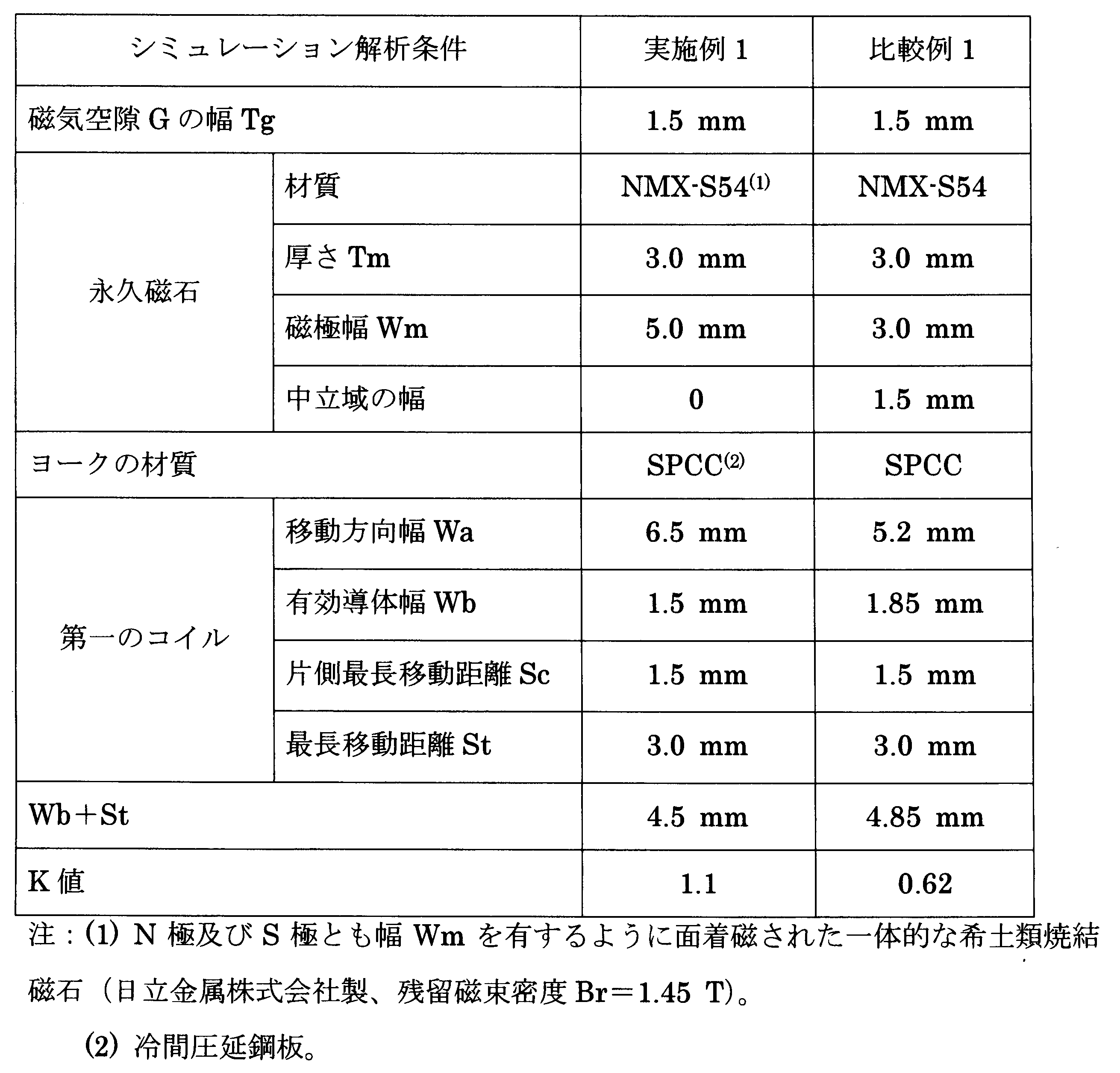
- Example 1 In the voice coil motor 6 for driving a correction lens of the present invention having the structure shown in FIG. 4 (a), a commercially available three-dimensional magnetic field analysis simulation software is used, and the first coil 12 is centered under the conditions shown in Table 1.
- the thrust of the first coil 12 was calculated when the one side longest moving distance Sc (1.5 mm) was moved from the position P0 to the F1 direction (X direction).
- the direct current supplied to the first coil 12 was 0.1 A, and the voltage was 2.0 V.
- the magnetic flux density in the magnetic gap G was 0.94 T, and the thrust constant was 2.4 to 2.7 N / A.
- the results are shown in FIG.
- a curve V1 shows a change in thrust of the first coil 12 in the voice coil motor of Example 1
- a curve V2 shows a change in thrust of the first coil 12 in the voice coil motor 6 of Comparative Example 1.
- the decrease in thrust when the correction lens 3 is moved about 1.5 mm in the X direction is as small as about 13%, but in the voice coil motor 20 of Comparative Example 1, the decrease in thrust is about It was 45%. Even if the first coil 12 moves by the one-side longest moving distance Sc, the reduction in the thrust in the first embodiment is 1/3 or less that in the first comparative example.
- the voice coil motor 6 of the present invention can maintain high thrust (excellent thrust linearity) over the entire movement range of the coil as compared with the voice coil motor 20 of Comparative Example 1. Further, the voice coil motor 6 of the present invention with a small reduction in thrust can reduce power consumption for correcting camera shake. Naturally, the voice coil motor 7 also has excellent thrust linearity over the entire movement range of the coil.
- the reason why the voice coil motor 6 of the present invention has excellent thrust linearity over the entire movement range of the coil as compared with the voice coil motor 20 of Comparative Example 1 is that the condition of 1 ⁇ Wm / (Wb + St) is satisfied. is there. Therefore, the first coil 12 moves in the region where the magnetic flux density is high (Wma shown in FIG. 7), and even if the first coil 12 approaches the end of the one-side longest moving distance Sc, the reduction in thrust is small. . This is the same even if the second coil 15 is driven in the Y direction.
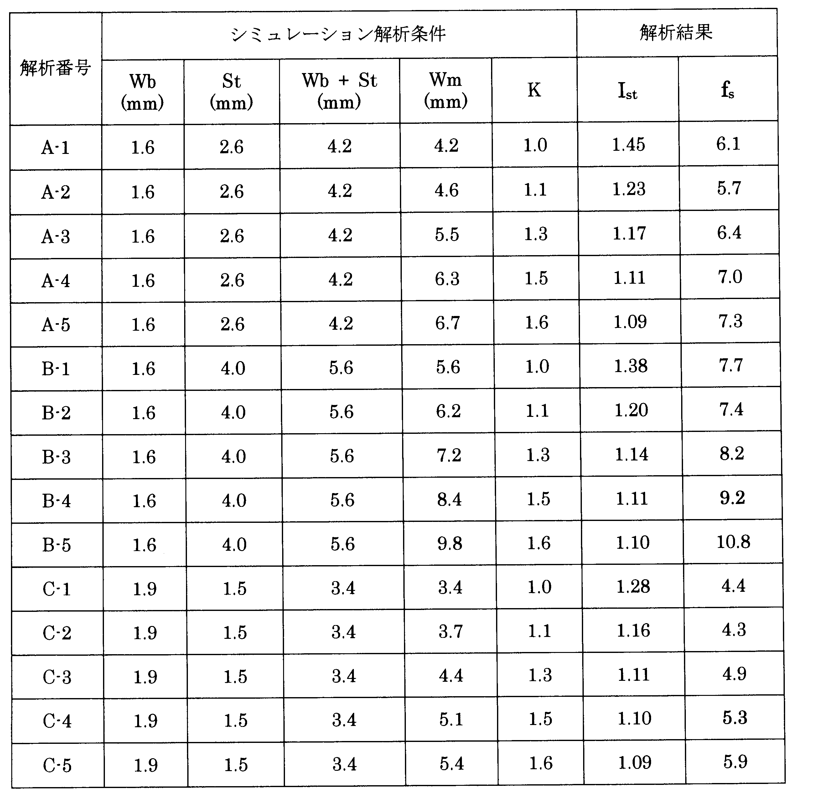
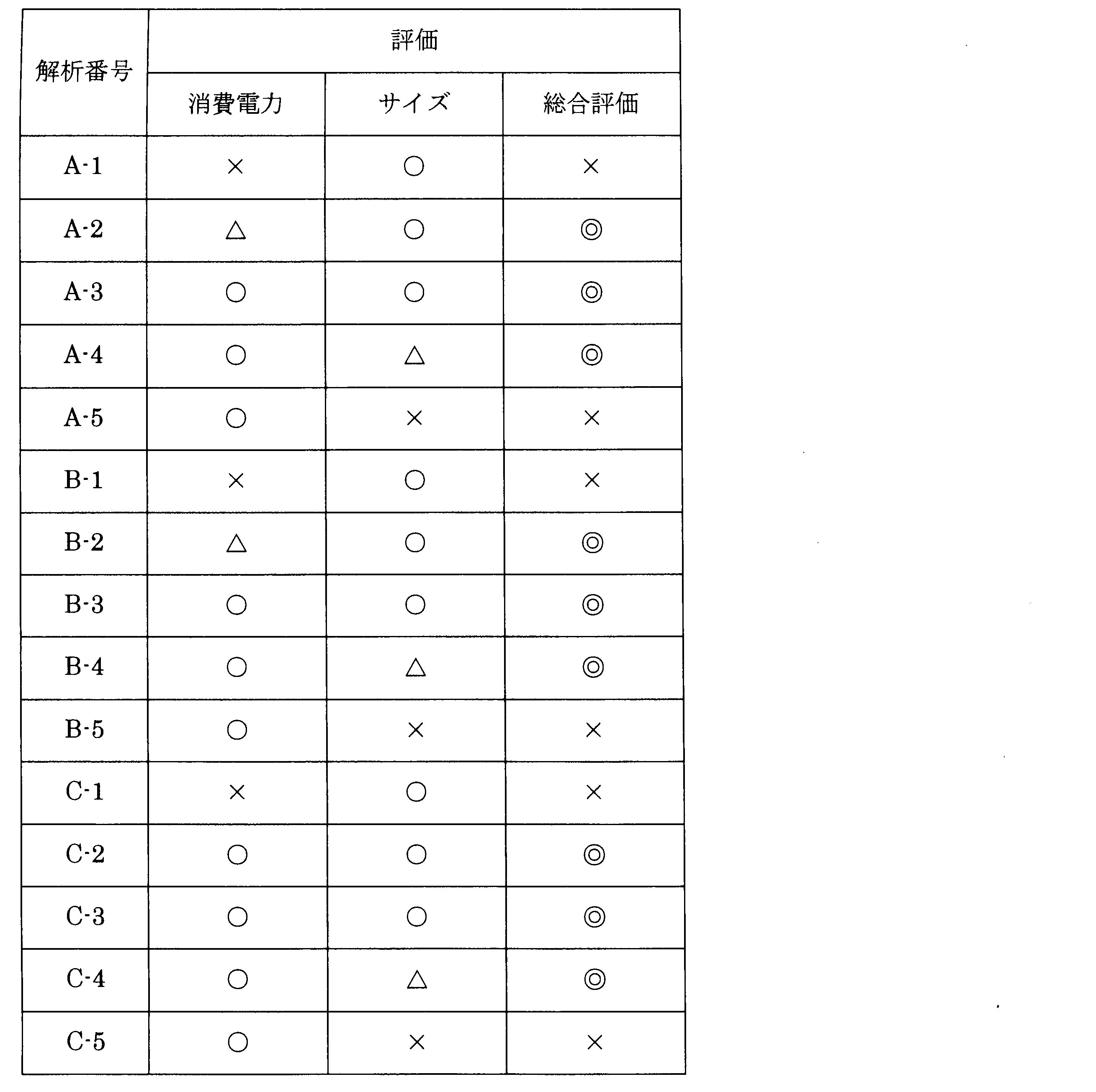
- Example 2 The power consumption of the first coil and the size of the voice coil motor were evaluated by the same magnetic field analysis simulation as in Example 1 except that the coil width, the longest moving distance, and the magnetic pole width were changed. The results are shown in Table 2.
- the size of the voice coil motor was evaluated by the product f s of the magnetic pole width Wm of the permanent magnet and the ratio I st .
- the evaluation criteria are as follows.
- the “minimum value” is a group of the same magnetic pole width Wb [A group (A-1 to A-5), B group (B-1 to B-5), and C group (C-1 to C-5)] means the minimum f s (A-2 5.7 in the A group, B-2 7.4 in the B group, and C-2 4.3 in the C group).
- ⁇ : f s is minimum value + 15% or less
- f s is minimum value + 15 to 25% or less
- f s is minimum value + 25% or more
- the image stabilization device with the above voice coil motor can be replaced with a wide-angle lens (for example, a lens having a focal length shorter than 40 mm) or a telephoto lens (for example, a lens having a focal length longer than 85 mm). It can also be mounted on lenses.
- a wide-angle lens for example, a lens having a focal length shorter than 40 mm
- a telephoto lens for example, a lens having a focal length longer than 85 mm
- the installation space for the voice coil motor is wide, so the magnetic pole width Wm that satisfies the condition 1 ⁇ Wm / (Wb + St) ⁇ 1.5 can be set large, and the correction amount accordingly. Therefore, the controllability of camera shake correction is improved.
- an interchangeable lens having a focal length of 600 mm or more it is effective to reduce the size of the voice coil motor for driving the correction lens in order to reduce the weight of the lens barrel as much as possible.
- the camera shake correction apparatus provided is suitable.
- the camera shake correction apparatus of the present invention is suitable for use in various optical devices such as digital cameras, video cameras, binoculars, surveillance cameras, and astronomical telescopes.
Landscapes
- Physics & Mathematics (AREA)
- General Physics & Mathematics (AREA)
- Optics & Photonics (AREA)
- Engineering & Computer Science (AREA)
- Multimedia (AREA)
- Signal Processing (AREA)
- Adjustment Of Camera Lenses (AREA)
- Reciprocating, Oscillating Or Vibrating Motors (AREA)
- Lens Barrels (AREA)
- Studio Devices (AREA)
Abstract
Description
前記永久磁石は磁気空隙対向面に移動方向に沿って異なる磁極を隣接して有し、
前記永久磁石の移動方向幅は前記磁極の幅Wmの2倍であり、
前記コイルの移動方向幅Waは前記永久磁石の幅2 Wmより狭く、
前記コイルの有効導体幅Wb、前記永久磁石の磁極幅Wm及び前記補正レンズの最長移動距離Stは、Wm=(Wb+St)×K(ただし、Kは1<K≦1.5を満たす定数)の条件を満たすことを特徴とする。
前記一対のボイスコイルモータ内の前記磁石ユニットを構成する一対のヨークは、両コイルが互いに直交する方向に移動するように前記鏡筒内で固定されており、
前記一対のコイルは前記補正レンズ支持枠体に固定されており、
前記一対のコイルは通電により前記磁気空隙内で直線的に移動し、もって前記補正レンズ支持枠体に支持された前記補正レンズは前記光軸と直交する面内で駆動されることを特徴とする。
(A) 全体構造
図1に示すように、撮影時の手振れ(例えば数Hz~数十Hzの周波数を有する振動)に起因する撮影画像の像振れを防止する手振れ補正装置1を具備する交換レンズは、鏡筒11内に、撮像レンズ10a、10b及びフォーカスレンズ(図示せず)とともに補正レンズ3を含む複数のレンズ群から構成される光学系を有する。手振れ補正装置1は、X方向(ピッチ方向)のカメラの縦振れ及びY方向(ヨー方向)の横振れからなる手振れを防止するために、振動検出部(振動検出センサ)が検出した振動に対応させて補正レンズ3をX方向及びY方向に駆動し、レリーズボタンをONしたときに撮像素子(CMOS又はCCD)2における結像位置を修正する機能を有する。
手振れ補正装置1に組込まれた第一及び第二の補正レンズ駆動用ボイスコイルモータ6及び7の構造を図2~図4に示す。
ボイスコイルモータ6,7を備えた手振れ補正装置1により撮影時の手振れを補正するシステムについて説明する。図6は、手振れ補正装置1を搭載した交換レンズ(例えばデジタル一眼レフカメラ用)における手振れ補正制御システムの一例を示す。
手振れ補正装置1を有する交換レンズを装着したデジタルカメラのレリーズボタン24を押圧すると、シャッターON信号がカメラ本体CPU 21に入力され、そこからシャッターONの制御コマンドが交換レンズ内の手振れ補正装置1に出力される。手振れ補正CPU 31はメモリ32から手振れ補正制御プログラムを読み出す。
第一及び第二のボイスコイルモータは本質的に同じ推力特性を有し、かつ各ボイスコイルモータ中の第一及び第二のコイルも本質的に同じ推力特性を有するので、第一のボイスコイルモータ6中の第一のコイル12を例にとって、推力特性を説明する。
本発明の補正レンズ駆動用ボイスコイルモータを磁場解析シミュレーションにより評価した結果、小型化及び消費電力の低減を両立させるための基本的条件は、磁極幅WmがWm=(Wb+St)×K、(ただしKは1<K≦1.5を満たす定数)の関係を満たすことである。定数Kは、永久磁石の磁気特性、手振れ補正装置及び交換レンズの各部の寸法(鏡筒の寸法等)等に応じて異なるが、第一のコイル12の全移動範囲にわたって良好な直線性を有する推力分布を得るためには、すなわち対向する永久磁石13a,13bの端部Pt近傍でも推力の低下を抑制するためには、K>1、すなわちWm>Wb+Stである必要がある。これにより、第一のコイル12が図4(a) に示すように中心位置P0に静止している状態から、図4(b) に示すようにF1方向(X方向)に片側最大距離Scだけ移動しても、第一のコイル12の巻線部12bは永久磁石13a,13bの端部Ptからはみ出さず、永久磁石13aのN極から永久磁石13bのS極へ向かう磁束を確実に横切る。その結果、第一のコイル12がF1方向へ片側最大距離Scだけ移動しても、第一のコイル12、すなわち補正レンズ支持枠体4を移動させる推力の低下が抑制される。
本発明の補正レンズ駆動用ボイスコイルモータは、推力を高めるとともにその直線性を高めるために、基本的条件の他に以下の付加的条件を満たすのが好ましい。
磁気空隙Gにおける磁束密度分布のピーク値が0.5 T以上である場合、コイルは大きな推力を出すことができる。
磁極幅Wmが一定の場合、片側最長移動距離Scを大きくすると、移動範囲の端に近づくほどコイルの推力は低下する。そこで、磁気空隙G内の磁束密度のピーク値を0.9 T以上とすることにより、1~2 mmの片側最長移動距離Scのとき、推力定数を2~4 N/Aとすることができ、最大移動範囲の端でも十分に大きな推力を与えることができる。
第一及び第二のコイル12,15の占積率は50%以上が好ましい。占積率が50%以上であると、本発明の補正レンズ駆動用ボイスコイルモータに例えば1.3 T以上の高い残留磁束密度Brを有する希土類焼結磁石を使用することにより所望の推力を得ることができる。コイル12,15の最長移動距離Stにわたって安定した推力を得るためには、第一及び第二のコイル12,15の占積率を70%以上とするのが好ましい。
図4(a) に示す構造を有する本発明の補正レンズ駆動用ボイスコイルモータ6において、市販の3次元磁場解析シミュレーション・ソフトウエアを利用し、表1に示す条件で第一のコイル12を中心位置P0からF1方向(X方向)に片側最長移動距離Sc(1.5 mm)だけ移動させたときの第一のコイル12の推力を求めた。第一のコイル12に供給する直流電流を0.1 Aとし、電圧を2.0 Vとした。また磁気空隙G内の磁束密度を0.94 Tとし、推力定数を2.4~2.7 N/Aとした。結果を図8に示す。推力は原点における推力を100%としたときの相対値で表す。実施例1の条件はWm=5.0 mm及び(Wb+St)=4.5 mmであるので、K=1.1であり、本発明の基本的条件を満たした。
特許第4181663号に記載されているように磁化されていない中立域13f1,13f2を有する図9(a) に示す構造を有するボイスコイルモータ20における第一のコイル12の推力を、表1に示す条件で実施例1と同じ磁場解析シミュレーションにより求めた。結果を実施例1と同様に図8に示す。比較例1の条件はWm=3.0 mm及び(Wb+St)=4.85 mmであるので、K=0.62となり、本発明の基本的条件を満たさなかった。
コイル幅、最長移動距離及び磁極幅を変更した以外実施例1と同じ磁場解析シミュレーションにより、第一のコイルの消費電力及びボイスコイルモータのサイズを評価した。結果を表2に示す。
最長移動距離(最長ストローク)に達したときに最大推力を発生するのに必要な電流Imと中心位置にあるときに流れる電流I0との比率Ist(=Im/I0)に比例して第一のコイルの消費電力が大きくなるので、第一のコイルの消費電力を比率Istにより評価した。評価基準は以下の通りである。
○:Istが1.0以上~1.20未満
△:Istが1.20以上~1.25未満
×:Istが1.25以上
ボイスコイルモータのサイズは、永久磁石の磁極幅Wmと比率Istとの積fsで評価した。評価基準は以下の通りである。ただし、「最小値」は、同じ磁極幅Wbのグループ[Aのグループ(A-1~A-5)、Bのグループ(B-1~B-5)、及びCのグループ(C-1~C-5)]のそれぞれにおける最小のfs(AのグループではA-2の5.7、BのグループではB-2の7.4、及びCのグループではC-2の4.3)を意味する。
○:fsが最小値+15%以内
△:fsが最小値+15超~25%以内
×:fsが最小値+25%超
各評価における○を2点とし、△を1点とし、合計を以下の基準で評価した。ただし×が1つでもあれば×とした。
◎:3点以上
○:2点
△:1点
×:消費電力とサイズの少なくとも一方が×の場合
上記ボイスコイルモータを備えた手振れ補正装置は、広角レンズ(例えば焦点距離が40 mmより短いレンズ)及び望遠レンズ(例えば焦点距離が85 mmより長いレンズ)を含むいずれの交換レンズにも搭載することができる。また焦点距離が400 mmより長い超望遠レンズに搭載する場合、ボイスコイルモータの設置スペースが広いので、1<Wm/(Wb+St)≦1.5の条件を満たす磁極幅Wmを大きく設定でき、それだけ補正量を大きくできるので、手振れの補正の制御性が向上する。特に焦点距離が600 mm以上の交換レンズでは、鏡筒の重量を極力少なくするのに補正レンズ駆動用ボイスコイルモータを小型化するのが有効であり、上記利点を有する本発明のボイスコイルモータを具備する手振れ補正装置は好適である。
Claims (13)
- 磁気空隙を形成する一対のヨーク及び少なくとも1つの永久磁石を有する磁石ユニットと、前記磁気空隙内に配置されたコイルとを備え、前記コイルに通電して前記磁石ユニットと前記コイルとを直線的に相対移動させることにより補正レンズを駆動するボイスコイルモータであって、
前記永久磁石は磁気空隙対向面に移動方向に沿って異なる磁極を隣接して有し、
前記永久磁石の移動方向幅は前記磁極の幅Wmの2倍であり、
前記コイルの移動方向幅Waは前記永久磁石の幅2 Wmより狭く、
前記コイルの有効導体幅Wb、前記永久磁石の磁極幅Wm及び前記補正レンズの最長移動距離Stは、Wm=(Wb+St)×K(ただし、Kは1<K≦1.5を満たす定数)の条件を満たすことを特徴とする補正レンズ駆動用ボイスコイルモータ。 - 請求項1に記載の補正レンズ駆動用ボイスコイルモータにおいて、前記磁石ユニットは一対のヨークと、一方のヨークの磁気空隙対向面に固着された1つの永久磁石とからなり、前記磁気空隙を介して他方のヨークと前記永久磁石が対向していることを特徴とする補正レンズ駆動用ボイスコイルモータ。
- 請求項1に記載の補正レンズ駆動用ボイスコイルモータにおいて、前記磁石ユニットは一対のヨークと、各ヨークの磁気空隙対向面に固着された一対の永久磁石とからなり、前記一対の永久磁石の対向面は異なる磁極を有することを特徴とする補正レンズ駆動用ボイスコイルモータ。
- 請求項3に記載の補正レンズ駆動用ボイスコイルモータにおいて、前記磁気空隙内の磁束密度分布のピーク値が0.5 T以上であることを特徴とする補正レンズ駆動用ボイスコイルモータ。
- 請求項1に記載の補正レンズ駆動用ボイスコイルモータにおいて、前記永久磁石が一体的であることを特徴とする補正レンズ駆動用ボイスコイルモータ。
- 請求項1に記載の補正レンズ駆動用ボイスコイルモータにおいて、前記一対のヨークの各々に永久磁石が固着されており、前記永久磁石の各々は移動方向に沿って隣接する一対の厚さ方向に磁化されたブロック状永久磁石からなり、前記ブロック状永久磁石は前記移動方向に並んだ磁極が異なるとともに対向する磁極も異なるように配置されていることを特徴とする補正レンズ駆動用ボイスコイルモータ。
- 請求項1に記載の補正レンズ駆動用ボイスコイルモータにおいて、前記ヨークの一方に永久磁石が固着されており、前記永久磁石は移動方向に沿って隣接する一対の厚さ方向に磁化されたブロック状永久磁石からなり、前記ブロック状永久磁石は前記移動方向に並んだ磁極が異なるように配置されていることを特徴とする補正レンズ駆動用ボイスコイルモータ。
- 請求項1に記載の補正レンズ駆動用ボイスコイルモータにおいて、前記永久磁石が1.3 T以上の残留磁束密度を有する希土類焼結磁石であることを特徴とする補正レンズ駆動用ボイスコイルモータ。
- 請求項1に記載の補正レンズ駆動用ボイスコイルモータにおいて、前記定数Kが1.1~1.5の範囲にあることを特徴とする補正レンズ駆動用ボイスコイルモータ。
- 請求項1に記載の補正レンズ駆動用ボイスコイルモータにおいて、前記磁石ユニットは固定されており、前記コイルが移動することを特徴とする補正レンズ駆動用ボイスコイルモータ。
- 撮像レンズを有する鏡筒内に設けられ、補正レンズと、光軸と直交する面内に支持された補正レンズ支持枠体と、請求項1に記載の一対の補正レンズ駆動用ボイスコイルモータとを備えた手振れ補正装置であって、
前記一対のボイスコイルモータ内の前記磁石ユニットを構成する一対のヨークは、両コイルが互いに直交する方向に移動するように前記鏡筒内で固定されており、
前記一対のコイルは前記補正レンズ支持枠体に固定されており、
前記一対のコイルは通電により前記磁気空隙内で直線的に移動し、もって前記補正レンズ支持枠体に支持された前記補正レンズは前記光軸と直交する面内で駆動されることを特徴とする手振れ補正装置。 - 請求項11に記載の手振れ補正装置と、振動検出部と、前記振動検出部が出力する振動信号に基づいて前記補正レンズ駆動用ボイスコイルモータの駆動を制御する手振れ補正制御手段とを備えていることを特徴とする交換レンズ。
- 請求項11に記載の手振れ補正装置と、振動検出部と、前記振動検出部が出力する振動信号に基づいて前記補正レンズ駆動用ボイスコイルモータの駆動を制御する手振れ補正制御手段とを備えていることを特徴とする光学機器。
Priority Applications (4)
| Application Number | Priority Date | Filing Date | Title |
|---|---|---|---|
| DE112010000767T DE112010000767T5 (de) | 2009-01-23 | 2010-01-22 | Schwingspulenmotor zum Bewegen einer Korrekturlinse, Schwingungsdämpfungsvorrichtung,wechselbare Linseneinheit und optische Vorrichtung |
| US13/145,946 US8817375B2 (en) | 2009-01-23 | 2010-01-22 | Correction-lens-moving voice coil motor, anti-vibration device, interchangeable lens unit and optical apparatus |
| CN2010800053687A CN102292673A (zh) | 2009-01-23 | 2010-01-22 | 校正透镜驱动用音圈电机、手抖动校正装置、交换透镜及光学设备 |
| JP2010547538A JP5308457B2 (ja) | 2009-01-23 | 2010-01-22 | 補正レンズ駆動用ボイスコイルモータ、手振れ補正装置、交換レンズ及び光学機器 |
Applications Claiming Priority (2)
| Application Number | Priority Date | Filing Date | Title |
|---|---|---|---|
| JP2009-012726 | 2009-01-23 | ||
| JP2009012726 | 2009-01-23 |
Publications (1)
| Publication Number | Publication Date |
|---|---|
| WO2010084965A1 true WO2010084965A1 (ja) | 2010-07-29 |
Family
ID=42356015
Family Applications (1)
| Application Number | Title | Priority Date | Filing Date |
|---|---|---|---|
| PCT/JP2010/050832 Ceased WO2010084965A1 (ja) | 2009-01-23 | 2010-01-22 | 補正レンズ駆動用ボイスコイルモータ、手振れ補正装置、交換レンズ及び光学機器 |
Country Status (5)
| Country | Link |
|---|---|
| US (1) | US8817375B2 (ja) |
| JP (1) | JP5308457B2 (ja) |
| CN (1) | CN102292673A (ja) |
| DE (1) | DE112010000767T5 (ja) |
| WO (1) | WO2010084965A1 (ja) |
Cited By (11)
| Publication number | Priority date | Publication date | Assignee | Title |
|---|---|---|---|---|
| CN102130567A (zh) * | 2011-01-21 | 2011-07-20 | 清华大学 | 一种音圈电机 |
| JP2012047824A (ja) * | 2010-08-24 | 2012-03-08 | Canon Inc | 像ブレ補正装置及び撮像装置 |
| CN105827096A (zh) * | 2016-05-13 | 2016-08-03 | 中南大学 | 一种音圈电机 |
| JP2017003933A (ja) * | 2015-06-16 | 2017-01-05 | リコーイメージング株式会社 | 駆動装置 |
| JP2017090587A (ja) * | 2015-11-06 | 2017-05-25 | キヤノン株式会社 | 振れ補正装置及び光学機器 |
| JP2017147831A (ja) * | 2016-02-16 | 2017-08-24 | ミネベアミツミ株式会社 | 振動発生器 |
| JP2018004859A (ja) * | 2016-06-30 | 2018-01-11 | 株式会社タムロン | アクチュエータ及びそれを備えたレンズユニット、カメラ |
| JP2020106859A (ja) * | 2012-06-29 | 2020-07-09 | エルジー イノテック カンパニー リミテッド | カメラモジュール |
| US11665416B2 (en) | 2020-03-13 | 2023-05-30 | Samsung Electro-Mechanics Co., Ltd. | Camera module |
| WO2024158016A1 (ja) * | 2023-01-24 | 2024-08-02 | Tdk株式会社 | ボイスコイルアクチュエータ |
| WO2025013607A1 (ja) * | 2023-07-12 | 2025-01-16 | ソニーグループ株式会社 | 交換レンズ及び撮像装置 |
Families Citing this family (21)
| Publication number | Priority date | Publication date | Assignee | Title |
|---|---|---|---|---|
| WO2013046816A1 (ja) * | 2011-09-29 | 2013-04-04 | オリンパス株式会社 | 像振れ補正装置及びそれを備えた撮像装置 |
| JP2013246415A (ja) * | 2012-05-29 | 2013-12-09 | Sony Corp | 像ぶれ補正装置及び撮像装置 |
| JP5995624B2 (ja) * | 2012-09-19 | 2016-09-21 | キヤノン株式会社 | 撮像装置および交換レンズ |
| KR101960493B1 (ko) | 2012-12-12 | 2019-07-15 | 삼성전자주식회사 | 광학조절장치 |
| JP6512753B2 (ja) * | 2014-05-27 | 2019-05-15 | キヤノン株式会社 | 撮像装置 |
| KR102322840B1 (ko) * | 2014-11-18 | 2021-11-08 | 엘지이노텍 주식회사 | 렌즈 구동장치 및 이를 포함하는 카메라 모듈 |
| US9621096B1 (en) * | 2015-09-29 | 2017-04-11 | Apple Inc. | Current recycling voice-coil-motor (VCM) driver circuit |
| CN108781256B (zh) * | 2016-03-09 | 2020-08-11 | Lg 电子株式会社 | 控制相机模块的自动聚焦的装置和方法 |
| US10247954B2 (en) | 2016-03-29 | 2019-04-02 | Ricoh Imaging Company, Ltd. | Stage apparatus having shake-correction function |
| JP2017184600A (ja) * | 2016-03-29 | 2017-10-05 | リコーイメージング株式会社 | ステージ装置 |
| US10554875B2 (en) * | 2016-11-21 | 2020-02-04 | Samsung Electro-Mechanics Co., Ltd. | Apparatus for controlling position of camera module using peak detection |
| US10855891B2 (en) | 2016-11-21 | 2020-12-01 | Samsung Electro-Mechanics Co., Ltd. | Apparatus for controlling position of camera module |
| EP3567847B1 (en) * | 2017-01-09 | 2024-12-11 | LG Innotek Co., Ltd. | Dual lens drive device, dual camera module, and optical device |
| JP6852432B2 (ja) | 2017-02-09 | 2021-03-31 | Tdk株式会社 | レンズ駆動装置及び電磁駆動ユニット |
| CN108508678B (zh) * | 2017-02-27 | 2021-11-09 | 纳木加有限公司 | Ois摄像头模块及包括该ois摄像头模块的双摄像头系统 |
| CN110692004B (zh) * | 2017-06-15 | 2021-12-21 | 华为技术有限公司 | 双摄像头模块 |
| CN107765392A (zh) * | 2017-11-29 | 2018-03-06 | 瑞声声学科技(苏州)有限公司 | 双镜头模组驱动装置 |
| EP3798724B1 (en) | 2018-05-23 | 2023-11-08 | LG Innotek Co., Ltd. | Lens driving apparatus, and camera module and optical device comprising same |
| EP4130836A3 (en) * | 2018-12-27 | 2023-05-24 | Tdk Taiwan Corp. | Optical system |
| CN212160190U (zh) * | 2019-07-26 | 2020-12-15 | 台湾东电化股份有限公司 | 光学元件驱动机构 |
| TWI850042B (zh) * | 2023-05-12 | 2024-07-21 | 大立光電股份有限公司 | 可變通光孔模組、成像鏡頭模組、相機模組與電子裝置 |
Citations (2)
| Publication number | Priority date | Publication date | Assignee | Title |
|---|---|---|---|---|
| JP2006094185A (ja) * | 2004-09-24 | 2006-04-06 | Pentax Corp | ステージ駆動機構 |
| JP2008263769A (ja) * | 2007-03-20 | 2008-10-30 | Shin Etsu Chem Co Ltd | ボイスコイルモータ用磁気回路及びボイスコイルモータ |
Family Cites Families (9)
| Publication number | Priority date | Publication date | Assignee | Title |
|---|---|---|---|---|
| JP2641172B2 (ja) | 1989-12-18 | 1997-08-13 | キヤノン株式会社 | 像ぶれ補正装置 |
| JPH04181663A (ja) | 1990-11-15 | 1992-06-29 | Sony Corp | 半田付用端子 |
| JP3692566B2 (ja) * | 1995-09-12 | 2005-09-07 | 株式会社ニコン | ブレ補正カメラ |
| US5926656A (en) * | 1997-03-11 | 1999-07-20 | Nikon Corporation | Vibration reducing apparatus and lens barrel |
| JP4181663B2 (ja) | 1998-06-30 | 2008-11-19 | キヤノン株式会社 | 補正光学装置、像振れ補正装置、カメラ及び交換レンズ |
| US6642826B1 (en) * | 2000-08-09 | 2003-11-04 | Sumitomo Special Metals Co., Ltd. | Magnetic field generator and assembling method thereof |
| JP2003172961A (ja) * | 2001-09-27 | 2003-06-20 | Nikon Corp | ブレ補正装置及び撮影装置 |
| JP2004088992A (ja) * | 2002-05-24 | 2004-03-18 | Murata Mfg Co Ltd | ボイスコイル型リニアアクチュエータ及びこのアクチュエータを用いた装置、並びにこのアクチュエータの製造方法 |
| JP5114970B2 (ja) | 2007-02-23 | 2013-01-09 | 株式会社ニコン | 相対移動部材、ブレ補正装置および光学装置 |
-
2010
- 2010-01-22 US US13/145,946 patent/US8817375B2/en not_active Expired - Fee Related
- 2010-01-22 DE DE112010000767T patent/DE112010000767T5/de not_active Withdrawn
- 2010-01-22 CN CN2010800053687A patent/CN102292673A/zh active Pending
- 2010-01-22 WO PCT/JP2010/050832 patent/WO2010084965A1/ja not_active Ceased
- 2010-01-22 JP JP2010547538A patent/JP5308457B2/ja not_active Expired - Fee Related
Patent Citations (2)
| Publication number | Priority date | Publication date | Assignee | Title |
|---|---|---|---|---|
| JP2006094185A (ja) * | 2004-09-24 | 2006-04-06 | Pentax Corp | ステージ駆動機構 |
| JP2008263769A (ja) * | 2007-03-20 | 2008-10-30 | Shin Etsu Chem Co Ltd | ボイスコイルモータ用磁気回路及びボイスコイルモータ |
Cited By (13)
| Publication number | Priority date | Publication date | Assignee | Title |
|---|---|---|---|---|
| JP2012047824A (ja) * | 2010-08-24 | 2012-03-08 | Canon Inc | 像ブレ補正装置及び撮像装置 |
| CN102130567A (zh) * | 2011-01-21 | 2011-07-20 | 清华大学 | 一种音圈电机 |
| JP7229193B2 (ja) | 2012-06-29 | 2023-02-27 | エルジー イノテック カンパニー リミテッド | カメラモジュール |
| JP2020106859A (ja) * | 2012-06-29 | 2020-07-09 | エルジー イノテック カンパニー リミテッド | カメラモジュール |
| JP2017003933A (ja) * | 2015-06-16 | 2017-01-05 | リコーイメージング株式会社 | 駆動装置 |
| JP2017090587A (ja) * | 2015-11-06 | 2017-05-25 | キヤノン株式会社 | 振れ補正装置及び光学機器 |
| JP2017147831A (ja) * | 2016-02-16 | 2017-08-24 | ミネベアミツミ株式会社 | 振動発生器 |
| CN105827096A (zh) * | 2016-05-13 | 2016-08-03 | 中南大学 | 一种音圈电机 |
| JP2018004859A (ja) * | 2016-06-30 | 2018-01-11 | 株式会社タムロン | アクチュエータ及びそれを備えたレンズユニット、カメラ |
| US11665416B2 (en) | 2020-03-13 | 2023-05-30 | Samsung Electro-Mechanics Co., Ltd. | Camera module |
| US12075147B2 (en) | 2020-03-13 | 2024-08-27 | Samsung Electro-Mechanics Co., Ltd. | Camera module |
| WO2024158016A1 (ja) * | 2023-01-24 | 2024-08-02 | Tdk株式会社 | ボイスコイルアクチュエータ |
| WO2025013607A1 (ja) * | 2023-07-12 | 2025-01-16 | ソニーグループ株式会社 | 交換レンズ及び撮像装置 |
Also Published As
| Publication number | Publication date |
|---|---|
| JPWO2010084965A1 (ja) | 2012-07-19 |
| CN102292673A (zh) | 2011-12-21 |
| JP5308457B2 (ja) | 2013-10-09 |
| US20110279899A1 (en) | 2011-11-17 |
| DE112010000767T5 (de) | 2012-09-27 |
| US8817375B2 (en) | 2014-08-26 |
Similar Documents
| Publication | Publication Date | Title |
|---|---|---|
| JP5308457B2 (ja) | 補正レンズ駆動用ボイスコイルモータ、手振れ補正装置、交換レンズ及び光学機器 | |
| EP3540492B1 (en) | Auto focus and optical image stabilization in a compact folded camera | |
| JP5821120B2 (ja) | 防振アクチュエータ、及びそれを備えたレンズユニット、カメラ | |
| CN101957535B (zh) | 防振致动器及包括该防振致动器的镜头单元、摄像装置 | |
| JP5731871B2 (ja) | 位置検出装置及びそれを用いたアクチュエータ | |
| US20160018720A1 (en) | Magnetic shielding between voice coil motors in a dual-aperture camera | |
| CN111226152B (zh) | 具有极坐标系统的镜头驱动器 | |
| JP5617408B2 (ja) | 駆動装置及び撮像装置 | |
| US9551881B2 (en) | Retention mechanism, driving apparatus, and blur correction apparatus | |
| JP2012242801A (ja) | 電磁駆動装置 | |
| JP6769696B2 (ja) | 位置検出装置 | |
| JP2011145526A (ja) | 防振アクチュエータ、及びそれを備えたレンズユニット、カメラ | |
| KR101398470B1 (ko) | 촬상 장치용 손떨림 보정 모듈 및 이를 구비한 촬상 장치 | |
| JP2012118517A (ja) | 手振れ補正ユニット | |
| WO2018223382A1 (en) | Lens actuator with ois and af function | |
| JP4899712B2 (ja) | レンズ鏡筒 | |
| JP6173416B2 (ja) | 位置検出装置 | |
| JP6235450B2 (ja) | 手振れ補正ユニット | |
| JP2017058169A (ja) | 位置検出装置及び光学装置 | |
| JP5446321B2 (ja) | 振れ補正装置および光学機器 | |
| JP2009163153A (ja) | レンズアクチュエータ | |
| JP2015064547A (ja) | 手振れ補正ユニット | |
| JP2013109248A (ja) | 防振アクチュエータ | |
| US20050168585A1 (en) | Anti-shake apparatus | |
| JP6432045B2 (ja) | アクチュエータ及びアクチュエータを備えるレンズ鏡筒 |
Legal Events
| Date | Code | Title | Description |
|---|---|---|---|
| WWE | Wipo information: entry into national phase |
Ref document number: 201080005368.7 Country of ref document: CN |
|
| 121 | Ep: the epo has been informed by wipo that ep was designated in this application |
Ref document number: 10733572 Country of ref document: EP Kind code of ref document: A1 |
|
| ENP | Entry into the national phase |
Ref document number: 2010547538 Country of ref document: JP Kind code of ref document: A |
|
| WWE | Wipo information: entry into national phase |
Ref document number: 13145946 Country of ref document: US |
|
| WWE | Wipo information: entry into national phase |
Ref document number: 112010000767 Country of ref document: DE Ref document number: 1120100007675 Country of ref document: DE |
|
| 122 | Ep: pct application non-entry in european phase |
Ref document number: 10733572 Country of ref document: EP Kind code of ref document: A1 |