WO2010084726A1 - シームレス蛍光ランプ用照明器具 - Google Patents
シームレス蛍光ランプ用照明器具 Download PDFInfo
- Publication number
- WO2010084726A1 WO2010084726A1 PCT/JP2010/000228 JP2010000228W WO2010084726A1 WO 2010084726 A1 WO2010084726 A1 WO 2010084726A1 JP 2010000228 W JP2010000228 W JP 2010000228W WO 2010084726 A1 WO2010084726 A1 WO 2010084726A1
- Authority
- WO
- WIPO (PCT)
- Prior art keywords
- socket
- fluorescent lamp
- lamp
- base
- seamless
- Prior art date
- Legal status (The legal status is an assumption and is not a legal conclusion. Google has not performed a legal analysis and makes no representation as to the accuracy of the status listed.)
- Ceased
Links
Images






Classifications
-
- H—ELECTRICITY
- H01—ELECTRIC ELEMENTS
- H01R—ELECTRICALLY-CONDUCTIVE CONNECTIONS; STRUCTURAL ASSOCIATIONS OF A PLURALITY OF MUTUALLY-INSULATED ELECTRICAL CONNECTING ELEMENTS; COUPLING DEVICES; CURRENT COLLECTORS
- H01R33/00—Coupling devices specially adapted for supporting apparatus and having one part acting as a holder providing support and electrical connection via a counterpart which is structurally associated with the apparatus, e.g. lamp holders; Separate parts thereof
- H01R33/05—Two-pole devices
- H01R33/06—Two-pole devices with two current-carrying pins, blades or analogous contacts, having their axes parallel to each other
- H01R33/08—Two-pole devices with two current-carrying pins, blades or analogous contacts, having their axes parallel to each other for supporting tubular fluorescent lamp
-
- F—MECHANICAL ENGINEERING; LIGHTING; HEATING; WEAPONS; BLASTING
- F21—LIGHTING
- F21V—FUNCTIONAL FEATURES OR DETAILS OF LIGHTING DEVICES OR SYSTEMS THEREOF; STRUCTURAL COMBINATIONS OF LIGHTING DEVICES WITH OTHER ARTICLES, NOT OTHERWISE PROVIDED FOR
- F21V19/00—Fastening of light sources or lamp holders
- F21V19/006—Fastening of light sources or lamp holders of point-like light sources, e.g. incandescent or halogen lamps, with screw-threaded or bayonet base
-
- F—MECHANICAL ENGINEERING; LIGHTING; HEATING; WEAPONS; BLASTING
- F21—LIGHTING
- F21Y—INDEXING SCHEME ASSOCIATED WITH SUBCLASSES F21K, F21L, F21S and F21V, RELATING TO THE FORM OR THE KIND OF THE LIGHT SOURCES OR OF THE COLOUR OF THE LIGHT EMITTED
- F21Y2103/00—Elongate light sources, e.g. fluorescent tubes
- F21Y2103/30—Elongate light sources, e.g. fluorescent tubes curved
-
- H—ELECTRICITY
- H01—ELECTRIC ELEMENTS
- H01J—ELECTRIC DISCHARGE TUBES OR DISCHARGE LAMPS
- H01J61/00—Gas-discharge or vapour-discharge lamps
- H01J61/02—Details
- H01J61/30—Vessels; Containers
- H01J61/32—Special longitudinal shape, e.g. for advertising purposes
- H01J61/327—"Compact"-lamps, i.e. lamps having a folded discharge path
-
- H—ELECTRICITY
- H01—ELECTRIC ELEMENTS
- H01R—ELECTRICALLY-CONDUCTIVE CONNECTIONS; STRUCTURAL ASSOCIATIONS OF A PLURALITY OF MUTUALLY-INSULATED ELECTRICAL CONNECTING ELEMENTS; COUPLING DEVICES; CURRENT COLLECTORS
- H01R33/00—Coupling devices specially adapted for supporting apparatus and having one part acting as a holder providing support and electrical connection via a counterpart which is structurally associated with the apparatus, e.g. lamp holders; Separate parts thereof
- H01R33/05—Two-pole devices
- H01R33/06—Two-pole devices with two current-carrying pins, blades or analogous contacts, having their axes parallel to each other
- H01R33/08—Two-pole devices with two current-carrying pins, blades or analogous contacts, having their axes parallel to each other for supporting tubular fluorescent lamp
- H01R33/0827—Two-pole devices with two current-carrying pins, blades or analogous contacts, having their axes parallel to each other for supporting tubular fluorescent lamp characterised by the contacts
-
- H—ELECTRICITY
- H01—ELECTRIC ELEMENTS
- H01R—ELECTRICALLY-CONDUCTIVE CONNECTIONS; STRUCTURAL ASSOCIATIONS OF A PLURALITY OF MUTUALLY-INSULATED ELECTRICAL CONNECTING ELEMENTS; COUPLING DEVICES; CURRENT COLLECTORS
- H01R33/00—Coupling devices specially adapted for supporting apparatus and having one part acting as a holder providing support and electrical connection via a counterpart which is structurally associated with the apparatus, e.g. lamp holders; Separate parts thereof
- H01R33/05—Two-pole devices
- H01R33/06—Two-pole devices with two current-carrying pins, blades or analogous contacts, having their axes parallel to each other
- H01R33/08—Two-pole devices with two current-carrying pins, blades or analogous contacts, having their axes parallel to each other for supporting tubular fluorescent lamp
- H01R33/0836—Two-pole devices with two current-carrying pins, blades or analogous contacts, having their axes parallel to each other for supporting tubular fluorescent lamp characterised by the lamp holding means
Definitions
- the present invention relates to a seamless fluorescent lamp, and more particularly to a lighting apparatus for a seamless fluorescent lamp of a type including a main pipe and a pair of auxiliary pipes provided near both ends thereof.
- FIG. 26 is a front view showing an example of the structure of a conventional fluorescent lamp socket 100 disclosed in, for example, Japanese Patent Laid-Open No. 9-17532.
- the socket main body 101 includes an insertion port 102 for inserting a pair of pins provided at one end of a straight tube fluorescent lamp, a vertical passage groove 103, and a rotation passage groove 104. Further, contact terminals 105 are provided on the left and right sides of the rotation passage groove 104, respectively. When the fluorescent lamp is mounted, the cap pin 106 of the fluorescent lamp is sandwiched between the contact terminals 105.
- the fluorescent lamp socket 100 having such a configuration is a first type socket for a straight tube fluorescent lamp.
- the pair of cap pins is set vertically, inserted into the insertion port 102 from the lower side of the socket, and then moved upward along the vertical passage groove 103. After reaching the end of the vertical passage groove 103, it is rotated by approximately 90 ° along the rotation passage groove 104 so as to be fixed while being sandwiched between the contact terminals 105.
- a metal receiving surface and a conductive terminal facing a base of a lamp are supported by a spring, and when a lamp is mounted, There is also a second type in which the metal receiving surface and the conductive terminal are pushed in the lamp axis direction.
- Two mainstreams are the second type socket and the first type socket that is inserted by rotating a base pin into a groove provided on the side of the socket and rotating.
- FIG. 27 is a front view (FIG. 27 (a)) and a partial plan view (FIG. 27 (b)) of a general seamless fluorescent lamp 200.
- the seamless fluorescent lamp 200 includes a main tube 81 made of a cylindrical glass tube, and an auxiliary tube provided on the side surfaces near both ends of the main tube 81 so that the center line thereof is substantially parallel. 82 is joined and connected so that the inside of the auxiliary pipe 82 and the main pipe 81 passes through the joint portion 83.
- a filament (not shown) is provided inside the end of the auxiliary tube 82 (opposite the joint 83), a base 84 is provided outside the end, and is further electrically connected to the base 84 from both ends of the filament via lead wires.
- a pair of the cap pins 85 formed so that the center line of the pair of cap pins 85 and the center line of the auxiliary pipe 82 are substantially parallel to each other, and a plane including the two center lines of the pair of cap pins 85 and two auxiliary pins.
- a plane including the center line of the pipe 82 and the main pipe 81 is provided so as to be substantially perpendicular.
- the seamless fluorescent lamp 200 has a feature that a dark portion cannot be formed at the end of the main tube 81 and a uniform light line can be formed when the seamless fluorescent lamps 200 are arranged in a straight line.
- the base 84 of the seamless fluorescent lamp 200 uses G5 as defined by JIS C7709.
- the axis of the base 84 substantially coincides with the central axis of the auxiliary tube 82 and a pair of adjacent bases.
- the plane including the pin 85 has a vertical positional relationship with the plane including the center line of the main pipe 81 and the auxiliary pipe 82. In this configuration, when the seamless fluorescent lamp 200 is provided on the normal ceiling, two adjacent cap pins 85 are arranged horizontally and held evenly.
- the seamless fluorescent lamp 200 is mounted on a lighting fixture, in the first type socket, when the auxiliary tube 82 is rotated, the main tube 81 whose center axis is apart from the auxiliary tube 82 must be moved greatly. Restrictions can be placed on the design of lighting fixtures, such as inability to install parts in the area.
- the force for pushing down the spring when inserted into the socket may cause the joint 83 to be displaced in the direction of the outer side of the main pipe 81 and may be damaged.
- stress continues to be applied after mounting, and the cap pin and the conductive terminal may be deformed and fixed, resulting in damage after use for a long time.
- the present invention has been made to solve the above-described problems.
- the seamless fluorescent lamp is mounted on a lighting fixture using a seamless fluorescent lamp of a type composed of one main pipe and a pair of auxiliary pipes.
- An object of the present invention is to provide a lighting device for a seamless fluorescent lamp with an increased degree of freedom in designing the lighting device.
- a lighting device for a seamless fluorescent lamp includes a main tube made of a cylindrical glass tube, and an auxiliary tube provided on the side surfaces in the vicinity of both end portions of the main tube so that the central axis thereof is substantially parallel.
- the auxiliary pipe is joined so that the main pipe and the inside penetrate in the vicinity of one end, and is electrically connected to the base outside the other end, the filament inside the other end, and the base from both ends of the filament
- the second support body fixes the side surface portion of the auxiliary tube.
- the second support fixes the lamp outer end of the auxiliary tube.
- the second support body also serves as one of the sockets, and one end of the second support body is fixed to the main body.
- one auxiliary tube is fixed by fixing a cap pin at the socket portion, and the other socket is not fixed to the main body.
- a lighting apparatus for a seamless fluorescent lamp includes a main tube made of a cylindrical glass tube, and an auxiliary tube provided on the side surfaces near both ends of the main tube so that the center line thereof is substantially parallel.
- the auxiliary pipe is joined so that the inside of the auxiliary pipe penetrates in the vicinity of one end, a filament is provided inside the other end, a base is provided outside the other end, and the base is electrically connected from both ends of the filament.
- a pair of base pins connected to each other so that the center line thereof is substantially parallel to the center line of the auxiliary pipe, and a plane including the two center lines of the pair of base pins and the centers of the two auxiliary pipes and the main pipe In a lighting device for a seamless fluorescent lamp using a seamless fluorescent lamp provided so that a plane including a line is substantially vertical,
- a pair of conductive terminals connected to the base pins are provided in a horizontal arrangement so that the horizontal base pins can be inserted vertically into the pair of conductive terminals from above.
- the distance from the lowermost surface of the socket to the uppermost position where the lower end of the side of the base pin must pass when the seamless fluorescent lamp is mounted is Lmm, If the diameter of the auxiliary tube is Dmm and the diameter of the cap pin is dmm, L ⁇ (D + d) / 2 + 4 It was made to become.
- the cap pin is directed upward from the respective positions corresponding to the tips of the pair of conductive terminals on the metal receiving surface of the socket facing the cap.
- An insertion hole through which the cap pin can pass is provided on the side surface of the socket.
- the cap pin is directed upward from the respective positions corresponding to the tips of the pair of conductive terminals on the metal receiving surface of the socket facing the cap. Are provided, and two insertion grooves through which the cap pin can pass are provided, and an insertion hole through which the cap pin can pass is provided on the side surface of the socket that has reached the side surface of the socket.
- a lighting device for a seamless fluorescent lamp includes a main tube made of a cylindrical glass tube, and an auxiliary tube provided on the side surfaces in the vicinity of both ends of the main tube so that its central axis is substantially parallel.
- the auxiliary pipe is joined so that the main pipe and the inside penetrate in the vicinity of one end, the base is outside the other end, the filament is inside the other end, and the base is electrically connected from both ends of the filament.
- a lighting device for a seamless fluorescent lamp using a seamless fluorescent lamp provided with a pair of connected cap pins, Provided with two sockets attached to the body of the lighting fixture for seamless fluorescent lamps, provided with a guide so that a part of the base side of the auxiliary pipe can be placed on the socket, and at least one socket is a center line of the main pipe It is designed to move in a direction substantially parallel to
- both the cap pins do not reach the socket in a state where the two sockets are moved closest to each other, and both the caps guide The length of the guide and the range of movement of the socket are set so that it can be mounted on the socket.
- a fluorescent lamp lighting apparatus includes a socket body having a pair of conductive terminals, A receiving surface side cover having a receiving surface and an outer peripheral surface that are fitted to the socket body and abuts against the lamp base; A lamp cap pin formed on the receiving surface of the cover on the receiving surface side, with one end opened to the outer peripheral surface, and the lamp cap pin inserted from the outer peripheral surface substantially parallel to the receiving surface to reach a pair of conductive terminals.
- An insertion groove, The lamp base pin insertion groove can be rotated around the center of the lamp base center axis without changing the position of the pair of conductive terminals, and the lamp base mounted on the base when rotating.
- the pin is configured to pass through.
- the socket has a pair of conductive terminals arranged substantially horizontally so that one lamp cap pin insertion groove is connected to both of the pair of conductive terminals. It is arranged.
- the socket has a pair of conductive terminals arranged substantially horizontally, and the pair of lamp cap pin insertion grooves are connected to the pair of conductive terminals, respectively. It is arranged.
- the lighting equipment for a seamless fluorescent lamp according to the first invention includes a main tube made of a cylindrical glass tube, and an auxiliary tube provided on the side surfaces near both ends of the main tube so that the central axis thereof is substantially parallel,
- the auxiliary pipe is joined so that the inside of the main pipe penetrates in the vicinity of one end, the base is connected to the outside of the other end, the filament is connected to the inside of the other end, and the pair is electrically connected to the base from both ends of the filament.
- a seamless fluorescent lamp lighting apparatus using a seamless fluorescent lamp provided with a cap pin, a plurality of first supports for fixing a main pipe, a second support for fixing at least one auxiliary pipe, and two sockets, Since at least one socket is not fixed to the main body, it can be installed without applying excessive force when installing a seamless fluorescent lamp. While preventing that a large stress is applied to the less fluorescent lamp, after mounting securely held, furthermore, it can be a range to move the lamp when mounting the seamless fluorescent lamp decreases to increase the degree of freedom in design of the luminaire.
- a lighting fixture for a seamless fluorescent lamp according to the second invention comprises a main tube made of a cylindrical glass tube, and an auxiliary tube provided on the side surfaces near both ends of the main tube so that its center line is substantially parallel,
- the auxiliary pipe is joined so that the inside of the auxiliary pipe penetrates in the vicinity of one end, a filament is provided inside the other end, a base is provided outside the other end, and the pair is electrically connected to the base from both ends of the filament.
- a lighting device for a seamless fluorescent lamp using a seamless fluorescent lamp provided so that In the socket, a pair of conductive terminals connected to the base pins are arranged horizontally, and the base pins are inserted into the pair of conductive terminals vertically from above, so that when installing a seamless fluorescent lamp Can be mounted without applying excessive force, prevents large stresses from being applied to the seamless fluorescent lamp during and after installation, holds it securely after installation, and further moves the lamp when installing the seamless fluorescent lamp It is possible to increase the degree of freedom in the design of the lighting fixture.
- a lighting apparatus for a seamless fluorescent lamp includes a main tube made of a cylindrical glass tube, and an auxiliary tube provided on the side surfaces near both ends of the main tube so that the central axis thereof is substantially parallel.
- the pipe is joined so that the inside of the main pipe penetrates in the vicinity of one end, the base is connected to the base outside the other end, the filament is inside the other end, and the pair is electrically connected to the base from both ends of the filament.
- a lighting device for a seamless fluorescent lamp using a seamless fluorescent lamp provided with a base pin Provided with two sockets attached to the body of the lighting fixture for seamless fluorescent lamps, provided with a guide so that a part of the base side of the auxiliary pipe can be placed on the socket, and at least one socket is a center line of the main pipe
- a seamless fluorescent lamp it can be installed without applying excessive force, preventing large stress from being applied to the seamless fluorescent lamp during and after installation.
- the lamp can be securely held after being mounted, and the range of movement of the lamp when the seamless fluorescent lamp is mounted can be reduced to increase the degree of freedom in designing the lighting fixture.
- a lighting apparatus for a fluorescent lamp includes a socket body having a pair of conductive terminals, a receiving surface side cover having a receiving surface and an outer peripheral surface which are fitted to the socket body and abut the lamp base, A lamp cap pin formed on the receiving surface of the cover on the receiving surface side, with one end opened to the outer peripheral surface, and the lamp cap pin inserted from the outer peripheral surface substantially parallel to the receiving surface to reach a pair of conductive terminals.
- An insertion groove, and the lamp cap pin insertion groove can be rotated about the lamp cap center line as a substantially central axis without changing the position of the pair of conductive terminals, and at the time of rotation Since the lamp cap pins attached to can be passed, it consists of one main pipe and a pair of auxiliary tubes, and further has a pair of cap pins parallel to the central axis on the end face of the auxiliary tubes Lighting seamless fluorescent lamp In addition to preventing large stresses from being applied to parts when mounting on fixtures, the seamless fluorescent lamp is securely held after mounting, and the range of movement of the lamp when mounting the seamless fluorescent lamp is reduced to reduce the lighting fixture design. The degree of freedom can be increased.
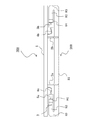
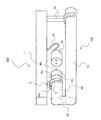
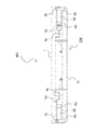
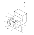
- FIG. 3 is a diagram showing the first embodiment of the first invention, and is an enlarged perspective view showing one end of FIG. 1.
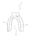
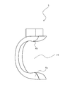
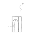
- FIG. 5 is a diagram showing the first embodiment of the first invention and a perspective view showing another example of the second support 3.
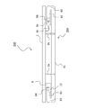
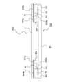
- It is a figure which shows Embodiment 2 of 1st invention, and is a front view of the lighting fixture 400 for seamless fluorescent lamps.
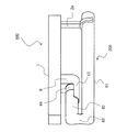
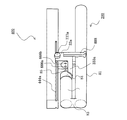
- FIG. 8 is a diagram showing a third embodiment of the first invention, and is an enlarged perspective view showing one end of FIG. 7. It is a figure which shows Embodiment 3 of 1st invention, and is a perspective view which expands and shows the 2nd support body and socket 9. FIG. It is a figure which shows Embodiment 4 of 1st invention, and is a perspective view which shows an example of the 1st and 2nd combined support body 13 which shared the 1st support body and the 2nd support body.
- FIG. 2nd invention The figure which shows Embodiment 1 of 2nd invention, and is the front view of the lighting fixture 300 for seamless fluorescent lamps after attaching the seamless fluorescent lamp 200.
- FIG. It is a figure which shows Embodiment 1 of 2nd invention, and is an enlarged perspective view of the socket 22a.
- FIG. 1 of 3rd invention The figure which shows Embodiment 1 of 3rd invention, and is a front view of the lighting fixture 300 for seamless fluorescent lamps before attaching the seamless fluorescent lamp 200.
- FIG. 1 of 3rd invention The figure which shows Embodiment 1 of 3rd invention, and is the front view of the lighting fixture 300 for seamless fluorescent lamps after attaching the seamless fluorescent lamp 200.
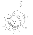
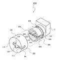
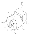
- Embodiment 1 of 4th invention It is a figure which shows Embodiment 1 of 4th invention, and is a perspective view before the lamp
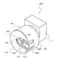
- Embodiment 2 of 4th invention It is a figure which shows Embodiment 2 of 4th invention, and is a perspective view of the state corresponding after the lamp
- Embodiment 1 of the First Invention 1 and 2 are views showing Embodiment 1 of the first invention
- FIG. 1 is a front view showing a lighting device 300 for a seamless fluorescent lamp
- FIG. 2 is an enlarged perspective view showing one end of FIG. It is.
- the former (FIG. 1) shows a state in which the seamless fluorescent lamp 200 is mounted
- the latter (FIG. 2) shows a state in the middle of mounting the seamless fluorescent lamp 200.
- the seamless fluorescent lamp 200 uses the general one shown in FIG.
- the seamless fluorescent lamp 200 may be simply referred to as a lamp.
- the main body 1 is provided with two first supports 2a and 2b and one second support 3.
- the first supports 2a and 2b may be plural.
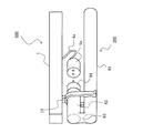
- the second support body 3 includes left and right arm portions 6a and 6b that can be opened and closed and a fulcrum 7 that supports the opening and closing thereof.
- the first supports 2a and 2b are springy, for example, made of synthetic resin.
- the first supports 2a and 2b sandwich and hold the main pipe 81 when the seamless fluorescent lamp 200 is mounted.
- the second support 3 holds and fixes at least the positional relationship between the main pipe 81 and the auxiliary pipe 82 with the auxiliary pipe 82 on the left side (in FIG. 1) interposed therebetween.
- the introduction electric wires 4a and 4b composed of two flexible electric wires have one end of each electric wire connected to a terminal of an inverter (not shown) provided in the main body 1, and the other end provided in the sockets 5a and 5b. Each is connected to two conductive terminals (not shown).
- the cap pin 85 is inserted into the conductive terminal, and the inverter to the filament are electrically connected. Since the sockets 5a and 5b are only connected to the main body 1 by flexible lead wires 4a and 4b, the positions thereof are determined by the seamless fluorescent lamp.
- the main pipe 81 is sandwiched and fixed between the first supports 2a and 2b.
- the auxiliary pipe 82 is positioned between the opened arm portions 6a and 6b of the second supporting body 3, the arm portions 6a and 6b are closed, and the auxiliary pipe 82 is sandwiched therebetween. Secure with.
- the fulcrum 7 can move the arm portions 6a and 6b around the fulcrum 7 by applying a certain force. However, if the force is not applied, the fulcrum 7 is pressed to the extent that it does not move. Next, the sockets 5a and 5b are moved, and the cap pin 85 is inserted into the conductive terminal to complete.
- the force applied to the lamp in the mounting operation is applied to the main tube 81 when the main tube 81 is sandwiched between the first supports 2a and 2b.
- almost no force is applied when the auxiliary pipe 82 is sandwiched between the second support bodies 3 and the base pin 85 is inserted into the sockets 5a and 5b. Power is added. Therefore, no force is applied to the joint 83, and the force applied to the other portions does not need to be large.
- the force necessary for contracting the spring corresponding to the length of the base pin is larger than these, and the side where the spring is pushed in and the base pin are Since the insertion side is the end on the opposite side, it is often difficult to insert and it is pushed in with a stronger force than necessary.
- both the base and the socket on both sides are inserted and rotated at the same time, so there is a possibility that unnecessary strong force may be applied without being successful.
- the possibility of damage caused by applying such a strong force is reduced.
- the seamless fluorescent lamp 200 is supported by the main pipe 81 portion of the first support bodies 2a and 2b, and the rotation is mainly controlled by the auxiliary pipe 82 portion and the second support body 3 is restricted.
- the joint 83, the base 84, or the base pin 85 is kept in a state where no stress is applied, so that the possibility of damage after use for a long time is reduced.
- the main pipe 81 it is necessary to turn the main pipe 81 around the axis of the auxiliary pipe 82 at the time of mounting, and there is a limitation in the instrument design that no parts can be placed in the space.
- the second support 3 is constituted by the fulcrum 7 that controls the opening and closing of the arm portions 6a and 6b, and the auxiliary pipe 82 can be easily fixed.
- the rotation about the axis of the main pipe 81 only needs to be restricted.
- the width is slightly wider than the diameter of the auxiliary pipe 82 and is open downward. Since rotation can be controlled, this is also acceptable.
- the opening 14 of the second support 3 may be simultaneously passed.
- the second support 3 may be fixed using an elastic plastic like the first support so as to open in the horizontal direction.
- the main tube 81 is fitted into the first supports 2a and 2b with the auxiliary tube 82 shifted from directly above the main tube 81, and then the seamless fluorescent lamp 200 is centered on the fixed main tube 81.
- the auxiliary tube 82 may be rotated and pushed into the openings 14 of the arm portions 6 a and 6 b of the second support 3.
- the second support 3 is provided as a single unit and is provided only on the left side, but the two left and right sides correspond to the two auxiliary pipes 82. It may be provided. In this case, since the position of the seamless fluorescent lamp 200 is more reliably and accurately fixed to the main body 1, there is an advantage that the optical positional relationship can be controlled more strictly.
- FIGS. 5 and 6 are views showing Embodiment 2 of the first invention
- FIG. 5 is a front view showing a lighting apparatus 400 for a seamless fluorescent lamp
- FIG. 6 is an enlarged perspective view showing a second support 3b. It is.
- the former (FIG. 5) shows a state where the seamless fluorescent lamp 200 is mounted.
- the configuration of the seamless fluorescent lamp lighting apparatus 400 will be described with reference to FIGS.
- the two second supports 3a and 3b are provided with a recess 8 so as to cover a part of the end surface and the side surface of the auxiliary tube 82 that is not on the base side.
- the end of the tube 82 is covered with the second supports 3a and 3b and fixed so as not to rotate.
- the other configuration except for the second supports 3a and 3b is the same as that of the first embodiment.
- the auxiliary tube 82 is set to a position directly above the main tube 81, and the end of the auxiliary tube 82 is placed along the indentation 8 of the second supporting bodies 3a and 3b and lifted from below. Then, the main pipe 81 is sandwiched and fixed to the first supports 2a and 2b from below. Next, the sockets 5a and 5b are moved, and the cap pin 85 is inserted into the conductive terminal to complete.
- the force applied to the lamp in the mounting operation is applied to the main pipe 81 when the main pipe 81 is sandwiched between the first supports 2a and 2b.
- the base pin 85 When the base pin 85 is inserted into the sockets 5a and 5b, the base pipe 81 is pressed to hold the base pipe 81.
- Force is applied only to the 84 part. Therefore, no force is applied to the joint portion 83, and the force applied to other portions does not need to be large, and therefore the possibility of breakage is reduced.
- the seamless fluorescent lamp 200 is supported by the main tube 81 portion of the first support 2a, 2b, and the rotation is controlled by the auxiliary tube 82 portion, and the second support 3a, 3b.
- the joint 83, the base 84, or the base pin 85 is kept in a state where no stress is applied, so that the possibility of damage after use for a long time is reduced.
- two second supports 3a and 3b are provided at both ends. Inferior but effective.
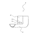
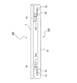
- FIGS. 7 to 9 are views showing Embodiment 3 of the first invention
- FIG. 7 is a front view showing a lighting device 500 for a seamless fluorescent lamp
- FIG. 8 is an enlarged view of one end of FIG.
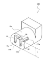
- FIG. 9 is an enlarged perspective view of the second support / socket 9. 7 and 8 show a state where the seamless fluorescent lamp 200 is mounted.
- the second support / socket 9 is fixed to the main body 1, and two conductive terminals (not shown) are fixed inside the second support / socket 9 and opened in the metal receiving surface 10.
- the base pin 85 is fixed through the pin insertion holes 11a and 11b.
- the joining of the conductive terminal and the terminal of the inverter is realized through the inside of the second support and socket 9 and further through the inside of the main body 1.
- a guide 12 for placing the auxiliary pipe 82 is provided on the auxiliary pipe 82 side below the second support body / socket 9. That is, the seamless fluorescent lamp 200 is fixed to the main body 1 by the two first supports 2 a and 2 b and the one second support and socket 9.
- the socket 5b at the other end is the same as the socket 5b in the first embodiment, and other configurations than the second support / socket 9 at the left end in FIG. It is the same.
- the auxiliary tube 82 is set to a position directly above the main tube 81, and is shifted to the left in FIG. 7 until the base 84 does not contact the guide 12, and the main tube 81 is moved from the bottom to the first position.
- the support bodies 2a and 2b are sandwiched and fixed.
- the entire seamless fluorescent lamp 200 is shifted to the right, and the base pin 85 is inserted into the pin insertion holes 11a and 11b while the auxiliary tube 82 is aligned with the guide 12, and is fixed by being sandwiched between the conductive terminals.
- the socket 5b is moved, and the right cap pin 85 is inserted into the corresponding conductive terminal to complete.
- the force applied to the lamp in the mounting operation is applied to the main pipe 81 when the main pipe 81 is sandwiched between the first supports 2a and 2b, and when the left and right cap pins 85 are inserted into the second support / socket 9 or the socket 5b. If the auxiliary tube 82 is pressed, a force is applied only to the base 84. Therefore, no force is applied to the joint portion 83, and the force applied to other portions does not need to be large, and therefore the possibility of breakage is reduced.
- the seamless fluorescent lamp 200 is slightly supported by the main tube 81 portion of the first support 2a, 2b and the second support / socket 9, but the joint 83 or the base 84 is used.
- the joint 83 or the base 84 is used.
- the first supports 2a and 2b are inserted elastically by inserting the main pipe 81 from the lower side. What is necessary is just to fix so that the position of a central axis may not be changed, and if other conditions, such as 2nd support body 3,3a, 3b, are satisfy
- the two arm portions 6a and 6b may be rotated at the fulcrum 7 in opposite directions to be opened and closed.
- the same effect can be obtained by using the first and second combined support bodies 13 which are used as the first support body and the second support body.
- the design of parts is slightly complicated, the number of parts is reduced, and the auxiliary pipe 82 and the main pipe 81 are mounted on the support (first and second combined support 13) at one place. Therefore, there is a merit that work becomes easy.
- the center line of the base 84 or the center line of the base pin 85 of the seamless fluorescent lamp 200 is substantially parallel to the center line of the auxiliary tube 82 and is a G5 base.
- the cap pin 85 is perpendicular to the center line of the auxiliary tube 82 and faces upward in the figure (FIG. 27). Also in this case, it is clear that this embodiment is generally effective.
- FIGS. 11 to 13 are views showing Embodiment 1 of the second invention.
- FIG. 11 is a front view of a lighting device 300 for a seamless fluorescent lamp after the seamless fluorescent lamp 200 is attached
- FIG. 12 is an enlarged perspective view of the socket 22a.
- 13 and 13 are enlarged perspective views of the conductive terminal 44a.
- the configuration of the seamless fluorescent lamp lighting apparatus 300 will be described with reference to FIGS.
- the seamless fluorescent lamp 200 the general one shown in FIG. 27 is used.
- the seamless fluorescent lamp 200 may be simply referred to as a lamp.
- Sockets 22 a and 22 b are attached to the side surface of the main body 1.
- the sockets 22a and 22b are provided with receiving surfaces 33a and 33b that face and are close to the base 84 of the seamless fluorescent lamp 200. See FIG. 12 for the receiving surface 33a.
- the receiving surface 33b is not shown.
- the sockets 22a and 22b are mirror-symmetrical. However, the sockets 22a and 22b may be exactly the same.
- the receiving surfaces 33a and 33b face each other outward.
- the sockets 22a and 22b are provided with a pair of conductive terminals 44a and 44b (see FIGS. 12 and 13) connected to the cap pins 85 therein.
- the conductive terminal 44b is the same as the conductive terminal 44a.
- socket terminals 55a and 55b cover the conductive terminals 44a and 44b from the outer periphery of the receiving surfaces 33a and 33b to the rear.
- socket side surface 55b is not illustrated.
- the conductive terminals 44a and 44b are provided with cap pins at connection positions 99a and 99b (99b not shown) so that the center line of the cap pin 85 is located in the direction from the front to the rear of the drawing.
- the insertion port 88a, 88b is opened by pressing the side surface of the base pin 85 against the insertion port 88a, 88b (88b is not shown) from above, so that the base pin 85 is opened. Passing through, moving to the connection positions 99a and 99b and getting stuck, it can be mounted.
- the conductive terminals 44a and 44b are tapered upward as shown in FIG. 13, but are inserted even when the cap pin 85 is to be inserted perpendicularly to the receiving surfaces 33a and 33b. As shown in the figure, the taper also opens to the base side.
- the conductive terminals 44a and 44b include a mechanism for fixing the conductive terminals 44a and 44b in the sockets 22a and 22b and wiring for electrically connecting to the inverter, but are omitted in FIG. .
- holes through which the cap pins 85 connected to the respective conductive terminals 44a and 44b pass are extended upward as passing holes 66, respectively, and further, the right side ( In FIG. 12), the direction is changed to extend, and further, while they merge, are further extended to reach the socket side surfaces 55a and 55b.
- the socket side surfaces 55a and 55b are provided with insertion holes 77a and 77b through which the cap pins 85 can pass.
- the sockets 22a and 22b are mirror-symmetrical.
- the cap pins 85 at both ends are moved to the vicinity of the side surfaces of the insertion holes 77a and 77b of both sockets 22a and 22b. And inserted into the insertion holes 77a and 77b from the cap pins 85 adjacent to the insertion holes 77a and 77b.
- the passage hole 66 is moved horizontally, moved to the end of the passage hole 66 in the horizontal direction, and then moved downward.
- the pair of base pins 85 reach the insertion ports 88a and 88b above the conductive terminals 44a and 44b almost simultaneously. Further, when a force is applied downward, the gaps between the insertion ports 88a and 88b of the conductive terminals 44a and 44b are opened, pass through the insertion ports 88a and 88b, and the connection positions 99a and 99b of the conductive terminals 44a and 44b. And are fixed by the springs (elastic force) of the conductive terminals 44a and 44b. Since the base pin 85 is directed upward, the base pin 85 is difficult to move in a direction to be removed due to gravity, and is further fixed by the springs of the conductive terminals 44a and 44b. Become.
- the force applied to the lamp in the mounting operation is applied when the cap pins 85 at both ends pass through the insertion ports 88a and 88b of the conductive terminals 44a and 44b of the sockets 22a and 22b, respectively, but at least the auxiliary tube 82 is applied. If it is performed while pressing, almost no stress is applied to the joint portion 83 and the like, and no large stress is applied to other portions.
- the force necessary for contracting the spring corresponding to the length of the base pin is larger than these, and the side where the spring is pushed in and the base pin 85 Since the side to insert is the opposite end, it is often difficult to insert it and it is pushed in with a stronger force than necessary.
- both the base and the socket on both sides are inserted and rotated at the same time, so there is a possibility that unnecessary strong force may be applied without being successful.
- the possibility of damage caused by applying such a strong force is reduced.
- the stress is continuously applied from both sides by the spring.
- the stress is not continuously applied. The possibility of damage after use for a while has decreased.
- the main pipe 81 it is necessary to turn the main pipe 81 around the axis of the auxiliary pipe 82 at the time of mounting, and there is a limitation in the instrument design that no parts can be placed in the space.
- ordinary sockets often have a substantially cylindrical shape whose receiving surface is close to the cross section of a fluorescent lamp bulb.
- the cap pin 85 is inserted into the insertion holes 77a and 77b from a position higher than the cap pin fixing position of the conductive terminals 44a and 44b and the passage hole 66 is moved as in the first embodiment, the main tube of the seamless fluorescent lamp 200 81, the lower ends of the sockets 22a and 22b come into contact with each other, and the base pin 85 does not reach the insertion holes 77a and 77b.
- the lower end of the sockets 22a and 22b is shaped like a cylinder and is brought closer to the conductive terminals 44a and 44b so that the base pin 85 reaches the insertion holes 77a and 77b. .
- the condition for the base pin 85 to reach the insertion holes 77a and 77b may be as follows.
- the distance between the auxiliary tube 82 and the main tube 81 is preferably as small as possible from the viewpoint of compactness of the lamp.
- a gap of about 2 mm is necessary from the manufacturing aspect. It was found that the compactness is not greatly affected. For this reason, 4 was added as the second term on the right side of Equation 1.
- D 16 mm
- d 2.3 mm
- L 6.5 mm
- Embodiment 2 of the second invention is diagrams showing Embodiment 2 of the second invention.
- FIG. 14 is a front view of a lighting device 400 for a seamless fluorescent lamp after the seamless fluorescent lamp 200 is attached.
- FIG. 15 is an enlarged perspective view of the socket 22a.
- FIG. 14 is a front view of a lighting device 400 for a seamless fluorescent lamp after the seamless fluorescent lamp 200 is attached.
- FIG. 15 is an enlarged perspective view of the socket 22a.
- the sockets 22a and 22b of the present embodiment will be described using the socket 22a as an example.
- holes through which the cap pins 85 connected to the respective conductive terminals 44a and 44b pass are extended upward as passing holes 66a and 66b, respectively. It has reached the upper surface of the side surface 55a.
- insertion holes 77a and 77b through which the cap pins 85 can pass are provided on the upper surface of the socket side surface 55a. Except for this, it is the same as the first embodiment except that the shape and dimensions of the socket side surface 55a are different.
- the conductive terminals 44a and 44b are also equivalent to those shown in FIG.
- the cap pins 85 at both ends are inserted into the insertion holes 77a, 77b, 77c, and 77d of both sockets 22a and 22b ( The latter two are moved to the vicinity of the upper part of the two (not shown) and inserted into the insertion holes 77a, 77b, 77c, 77d.
- passage holes 66a, 66b, 66c, 66d are moved vertically downward.
- the pair of base pins 85 reach the insertion ports 88a and 88b on the upper side of the conductive terminals 44a and 44b almost simultaneously.
- the gaps between the insertion ports 88a and 88b of the conductive terminals 44a and 44b are opened, pass through the insertion ports 88a and 88b, and the connection positions 99a and 99b of the conductive terminals 44a and 44b. Etc., and fixed by the springs of the conductive terminals 44a and 44b. Since the base pin 85 has the passage holes 66a, 66b, 66c, and 66d facing upward, it is difficult to move in a direction to be released due to gravity, and is further fixed by the springs of the conductive terminals 44a and 44b. It will be fixed to.
- the force applied to the lamp in the mounting operation is applied when the cap pins 85 at both ends pass through the insertion ports 88a and 88b of the conductive terminals 44a and 44b of the sockets 22a and 22b, respectively, but at least the auxiliary tube 82 is applied. If it is performed while pressing, almost no stress is applied to the joint portion 83 and the like, and no large stress is applied to other portions. For this reason, in this Embodiment 2, possibility of the damage by applying a strong force became small.
- Embodiment 2 Even after the mounting, in Embodiment 2, the stress was not continuously applied, and the possibility of breakage after use for a long time was reduced.
- the space required for mounting is small, and the degree of freedom in designing the lighting fixture is increased.
- the uppermost position where the lower end of the side surface of the base pin 85 must pass is the upper end of the socket side surfaces 55a and 55b.
- the distance between the upper surface and the upper surface, that is, L was reduced. That is, the portion close to the base of the socket was not a cylindrical shape, but a shape in which the cylinder was crushed from both sides.
- D 16 mm
- d 2.3 mm
- L 9 mm, which satisfies Expression 1.
- the base pin 85 does not pass through the passage holes 66, 66a, 66b because the passage holes 66, 66a, 66b are facing upward, and the conductive terminals 44a, 44b This is because it is pressed by the spring, but in order to more securely fix the base pin 85, a stopper that stops the movement of the base pin 85 or the base 84 may be provided.
- a support body for holding the main pipe 81 may be provided.
- the support is configured to suppress only the downward movement, particularly when there is a possibility that stress is applied upward, the base pin 85 may be displaced from the conductive terminals 44a and 44b due to the stress. is there.
- the support is configured not only to move downward but also to suppress upward movement.
- FIGS. 16 to 19 are diagrams showing Embodiment 1 of the third invention.
- FIG. 16 is a front view showing a state before the seamless fluorescent lamp 200 of the lighting apparatus 300 for a seamless fluorescent lamp is mounted.
- FIG. 18 is a front view of the seamless fluorescent lamp luminaire 300 after the lamp 200 is attached,
- FIG. 18 is an enlarged perspective view of a part of the seamless fluorescent lamp luminaire 300 before the seamless fluorescent lamp 200 is attached, and
- FIG. It is an expansion perspective view of a part of lighting fixture 400 for seamless fluorescent lamps (modification example) before attaching.
- the configuration of the lighting apparatus 300 for a seamless fluorescent lamp will be described with reference to FIGS.
- the seamless fluorescent lamp 200 the general one shown in FIG. 27 is used.
- the seamless fluorescent lamp 200 may be simply referred to as a lamp.
- Sockets 22a and 22b are attached to socket movement grooves 444a and 444b provided on the side surface of the main body 1, respectively.
- the sockets 22a and 22b are provided with guides 333a and 333b on which the auxiliary pipe 82 or a base 84 provided at the end thereof can be placed on the lower side.
- the socket moving grooves 444a and 444b are formed substantially parallel to the center line of the auxiliary pipe 82, and the sockets 22a and 22b assist along the socket moving grooves 444a and 444b within the range of the socket moving grooves 444a and 444b.
- the center line of the tube 82 that is, the center line of the main tube 81 can be moved substantially in parallel.
- Stoppers 777a and 777b are attached to the sockets 22a and 22b. The movement of the sockets 22a and 22b parallel to the center line of the auxiliary pipe 82 can be stopped by screwing the stoppers 777a and 777b by hand.
- FIG. 16 shows a state in which the sockets 22a and 22b are brought closest to each other within the movable range.
- both bases 84 of the seamless fluorescent lamp 200 are simultaneously mounted on the guides 333a and 333b, and further, the base pin 85 does not reach the sockets 22a and 22b or the receiving surface 555 thereof (see FIG. 18).
- the lengths of the guides 333a and 333b are made larger than the length of the base pin 85, and the lengths of the socket moving grooves 444a and 444b are shortened to the limit.
- both the caps 84 are substantially in contact with the receiving surfaces 555 of the sockets 22a and 22b, and the cap pins 85 are pin insertion holes 666a and 666b (see FIG. 18). And is electrically connected by being sandwiched between conductive terminals (not shown) provided in the sockets 22a and 22b.
- the inverter (not shown) provided in the main body 1 via the electric wire (not shown) which passes the socket 22a, 22b and the inside of the main body 1 from a conductive terminal, and eventually from the inverter Electrical connection is made up to the filament.
- the stoppers 777a and 777b are loosened and moved.
- the sockets 22a and 22b are moved to the right and left sides of the movable range, that is, the positions where the distance between the sockets 22a and 22b is minimized, and both the auxiliary pipes 82 or the caps 4 are moved to both the guides 333a and 333b.
- the lamp is positioned on the side surface of the lighting fixture (before the surface of the position of the seamless fluorescent lamp 200 in FIG. 16), in this example, one of the left and right ends, for example, the end face of the left base 84 is the guide 333a.
- the sockets 22a and 22b are moved in the direction in which the interval is increased (outside), and the cap pin 85 is brought into contact with the receiving surface 555 or the pin insertion holes 666a and 666b.
- the other socket 22b is moved further outward while holding the auxiliary pipe 82. Go.
- the base pin 85 is inserted into the pin insertion holes 666a and 666b, and is eventually sandwiched and fixed by the conductive terminals.
- the base pin 85 is inserted into the pin insertion holes 666a and 666b, and the end of the base pin 85 is finally fixed by being sandwiched between the conductive terminals. Further, the stoppers 777a and 777b are screwed by hand so that the sockets 22a and 22b do not move.
- the force applied to the lamp in the mounting operation is applied when the cap pins 85 at both ends are inserted into the sockets 22a and 22b, respectively, but at least if the auxiliary tube 82 is pressed, the joint 83 and the like have almost no stress. In addition, no great stress is applied to other parts.
- the force required for contracting the spring corresponding to the length of the base pin is larger than these, and the side for pushing the spring and the base pin are inserted. Since the side is the opposite end, it is often difficult to insert and it is pushed in with a stronger force than necessary.
- both the base and the socket on both sides are inserted and rotated at the same time, so there is a possibility that unnecessary strong force may be applied without being successful.
- the possibility of damage caused by applying such a strong force is reduced.
- the conventional second type socket continues to be stressed from both sides by the spring.
- such stress is not continuously applied, and the possibility of damage after long-time use is reduced.
- the main pipe 81 it is necessary to turn the main pipe 81 around the axis of the auxiliary pipe 82 at the time of mounting, and there is a limitation in the instrument design that no parts can be placed in the space.
- the sockets 22a and 22b are screwed-in type stoppers 777a and 777b, but the sockets 22a and 22b are displaced due to vibration or the like for a long time after the mounting, and the base pin 85 is moved. It is attached to prevent it from coming off.
- the stoppers 777a and 777b are not limited to this method as long as they can be securely stopped after being mounted.
- the socket moving grooves 444a and 444b may be provided with a step that falls downward, and may be stopped, or the main body 1 may be provided with a type that is lowered to the back of the sockets 22a and 22b. If the holding force of the base pin 85 of the conductive terminal is sufficient, or if the friction between the socket moving grooves 444a and 444b and the sockets 22a and 22b is sufficient, it can be confirmed that they do not shift for a long time.
- the stoppers 777a and 777b are not necessary.
- the lengths of the socket moving grooves 444a and 444b are adjusted so that the lamps can be easily placed when the sockets 22a and 22b are moved to the shortest. Although time is required for alignment, this length may be further increased.
- the socket moving grooves 444a and 444b are lengthened and the sockets 22a and 22b are brought closer, After the lamp is moved in parallel from the front of the sheet of FIG. 16 to the socket central axis, the socket can be moved and placed as shown in FIG. 16, eliminating the need to move left and right. In particular, there is an advantage that there is no possibility that the lamps interfere with each other when the lighting fixtures are closely arranged.
- the guide 333a, 333b has a height H that covers about 3 of the diameter of the auxiliary pipe 82, but the height H is lowered, If the distance between the auxiliary tube 82 and the main tube 81 (in the example, 4 mm) or less is used, similarly, there is no need to move the lamp to the left and right. It can be placed on 333a, 333b. On the other hand, when the height H of the guide is increased, the auxiliary pipe is less likely to fall off the guide during the mounting operation, and the operation is easier.
- the socket moving grooves 444a and 444b are provided on the outer side surfaces on both sides of the main body 1.
- the socket moving grooves 444a and 444b may be fixed in a state in which only the movement of the sockets 22a and 22b is possible.
- a groove may be provided on the inner side of the main body 1 or a convex band may be provided instead of the groove.
- both the sockets 22a and 22b are movable, but only one of them may be used. Although there is an advantage that it becomes simpler, the required moving distance of the movable side socket is doubled. Therefore, when reinforcing is provided between the main pipe 81 and the auxiliary pipe 82, the guides 333a and 333b are connected. There is also a drawback that interference is likely to be a problem.
- the lamp mounting operation is further simplified. That is, if the main pipe 81 is held by the support body 888 at the same time when the auxiliary pipe 82 or the base 84 is placed on the guides 333a and 333b, the lamp is less likely to be detached from the guides 333a and 333b during the work. This is particularly effective when the socket movement grooves 444a and 444b are lengthened.
- the support body 888 is provided in the sockets 22a and 22b.
- the relative positional relationship between the support body 888 and the sockets 22a and 22b can be set accurately.
- the support body 888 is fixed to the main body 1, it is possible to accurately set the positions of the main body 1 and the sockets 22a and 22b and the positions of the main body 1 and the support body 888. Is obtained.
- the metal receiving surface 555, the pin insertion holes 666a and 666b, and the conductive terminal are configured to rotate with respect to the socket body, or the pin insertion holes 666a and 666b are expanded at least in the circumferential direction, It is preferable to take measures such as increasing the range (circumferential direction) in which the conductive terminals are properly sandwiched.
- Embodiment 1 of the Fourth Invention 20 to 22 are diagrams showing Embodiment 1 of the fourth invention.
- FIG. 20 is a perspective view of the socket 3000 of the lighting fixture before insertion of the lamp
- FIG. 21 corresponds to after insertion of the lamp of the socket 3000 of the lighting fixture.
- FIG. 22 is a perspective view of a state in which a part of the socket 3000 of the lighting fixture is disassembled.
- the socket 3000 includes a main body 1 (socket main body) of the socket 3000 and a receiving surface side cover 222 that fits into the main body 1.
- Two conductive terminals 30a and 30b are fixed to the main body 1 side by side.
- the fixing means for the conductive terminals 30a and 30b, the wiring between the conductive terminals 30a and 30b and the inverter (not shown), and the fixing means for the socket 3000 to the lighting fixture (not shown) are not shown.
- the conductive terminals 30a and 30b are made of an elastic metal plate and are configured to hold the lamp cap pins from above and below. Further, the conductive terminals 30a and 30b are formed with a recess 444 (see FIG. 22) for fixing the position of the cap pin at the position where the cap pin is inserted. Furthermore, a gap is opened when force is applied so that one conductive terminal 30a (the left side in FIGS. 20 to 22) can pass the lamp cap pin from the other conductive terminal 30b side and the conductive terminal 30b from both sides. ing.
- a taper 555 (see FIG. 22) is provided so that the cap pin can pass smoothly.
- a notch 606 (see FIG. 22) having a dimension that allows the lamp cap pin to pass through is formed on the side surface 130 of the main body 1 of the socket 3000 facing the conductive terminal 30b. This notch 606 corresponds to the lamp cap pin passing position of the conductive terminals 30a, 30b.
- a narrow holding recess 707 (see FIG. 22) is provided on the side surface of the main body 1 in a circumferential shape.
- the receiving surface side cover 222 includes a plurality of hooks inside the holding surface 110 opposite to the receiving surface 110 so as to enter the holding recess 707 and prevent it from coming off.
- four hooks are formed at intervals of 90 °, or three hooks are formed at intervals of 120 °. This hook holds the receiving surface side cover 222 against the main body 1 so as not to move in the axial direction, but the rotational direction moves.
- four or three stoppers 808 (see FIG. 22) corresponding to the hooks are provided in the holding recesses 707 at intervals of 90 ° or 120 °, and turn slightly less than 90 ° or less than 120 °. There is no way.
- a notch 99 dimensioned to allow the lamp cap pin to pass through on the side surface 130 (outer peripheral surface) of the receiving surface side cover 222, and the lamp cap pin passes through the receiving surface 110.
- An insertion groove 111 is provided from the notch 99 horizontally to the conductive terminals 30a and 30b.
- the insertion groove 111 is defined as a lamp cap pin insertion groove.
- the insertion groove 111 is concentrically changed from the respective positions facing the conductive terminals 30a and 30b by approximately 90 °, and one (corresponding to the conductive terminal 30a) is directed upward and the other (conductive terminal 30b). (Corresponding to) extends downward (in the case of FIGS. 20 and 22).
- the position is continued to a position slightly less than 90 ° with respect to the central axis, where the end 120 of the insertion groove 111 is used.
- the stopper 808 of the main body 1 is not necessarily required, but there is an effect of increasing the accuracy of the regulation width of the rotation angle.
- Two sockets 3000 are provided on both sides of the luminaire, with the receiving surface 110 facing outward, and in accordance with the distance between the lamp caps.
- the receiving surface side cover 222 of the socket 3000 at both ends of the lighting fixture is set at the rotational position shown in FIG. That is, the notch 99 of the receiving surface side cover 222 and the notch 606 of the main body 1 face each other, and the insertion groove 111 of the receiving surface side cover 222 and the conductive terminals 30a and 30b face each other.
- a pair of lamp cap pins are inserted into one socket 3000 from the notch 99 connected to the insertion groove 111 and moved to the positions of the conductive terminals 30a and 30b.
- the cap pin that is moved to the position of the conductive terminal 30a passes through the cutout 99 of the receiving surface side cover 222, the cutout 606 of the main body 1, and the conductive terminal 30b (the lamp cap pin can pass from both sides). 30a.
- the cap pin moved to the position of the conductive terminal 30b passes through the notch 99 of the receiving surface side cover 222 and the notch 606 of the main body 1 and reaches the conductive terminal 30b.
- each receiving surface side cover 222 is rotated (in the direction of the arrow in FIGS. 20 and 21), and the lamp cap pin is fixed so as not to move along the insertion groove 111.
- the pair of lamp cap pins fit into the end 120 of the corresponding insertion groove 111, respectively.
- the insertion groove 111 can be rotated about the lamp cap center line as a substantially central axis without changing the positions of the conductive terminals 30a and 30b, and at the time of rotation, the insertion surface 111 can be formed on the reception surface 110. It is configured to allow the attached lamp cap pin to pass through.
- the lamp receiving side cover 222 may be rotated and fixed with respect to one socket 3000, and then the lamp cap pin may be inserted into the other socket 3000.
- the force applied at the time of mounting is necessary when the cap pin moved to the position of the conductive terminal 30a passes through the conductive terminal 30b and when the cap pin enters the conductive terminal 30a and the conductive terminal 30b.
- a large force (second type socket of the conventional example) is not required as compared with the force necessary to cause the spring to contract correspondingly.
- the second type since the end on which the spring is pushed in and the side on which the cap pin is inserted are opposite ends, it is often difficult to insert the pin with a force stronger than necessary. The possibility of breakage due to such a strong force was reduced. Further, by rotating the metal receiving surface side cover 222, the lamp cap pin is not displaced from between the conductive terminals 30a and 30b and is reliably held.
- FIGS. 23 to 25 are diagrams showing Embodiment 2 of the fourth invention.
- FIG. 23 is a perspective view of the socket 4000 of the lighting fixture before the lamp is inserted
- FIG. 24 is a state corresponding to the socket 4000 after the lamp of the lighting fixture is inserted
- FIG. 25 is a perspective view of a state in which a part of the socket 4000 of the lighting fixture is disassembled.
- the socket 4000 includes a socket body 1 and a receiving surface side cover 222.
- Two conductive terminals 30a and 30b are fixed to the main body 1 side by side.
- the fixing means for the conductive terminals 30a and 30b, the wiring between the conductive terminals 30a and 30b and the inverter (not shown), and the fixing means for the socket 3000 to the lighting fixture (not shown) are not shown.
- the conductive terminals 30a and 30b are made of an elastic metal plate and are configured to hold the lamp cap pins from the left and right in the figure.
- the conductive terminals 30a and 30b are formed with a recess 444 (see FIG. 25) for fixing the position of the base pin at the position where the base pin is inserted.
- Each of the conductive terminals 30a and 30b has a taper 555 so that the gap on the lower side is opened when a force is applied so that the lamp cap pin can be attached and detached from the lower side in the drawing, and can pass smoothly. ing.
- a notch 6 having a dimension capable of allowing two lamp cap pins to pass to the conductive terminals 30a and 30b side is formed in the lower part of the side surface of the end portion of the socket body on the conductive terminals 30a and 30b side.
- the side surface portion of the main body 1 and the receiving surface side cover 222 are provided with a holding mechanism similar to that of the first embodiment, and are held so as not to move in the axial direction but move in the rotational direction.
- the holding mechanism enters the holding recess 707 formed in the side surface portion of the main body 1, the stopper 808 (see FIG. 25) provided in the holding recess 707, and the holding recess 707 provided in the metal receiving surface side cover 222 so as not to come off. It is comprised by the hook (not shown) for doing. Since the operation of the holding mechanism is the same as that of the first embodiment, the description thereof is omitted.
- Two notches 99a and 99b having dimensions that allow the lamp cap pins to pass therethrough are formed below the side surface 130 (FIGS. 23 and 25) of the receiving surface side cover 222 in correspondence with the conductive terminals 30a and 30b. ing.
- the receiving surface 110 is provided with two insertion grooves 111a and 111b through which the lamp cap pins pass, extending vertically from the two notches 99a and 99b to the conductive terminals 30a and 30b.
- one of the concentric circles (corresponding to the conductive terminal 30a) is bent upward while the other (corresponding to the conductive terminal 30b) is bent downward.
- the position is continued to a position slightly less than 90 ° with respect to the central axis, and the ends 120a and 120b of the insertion grooves 111a and 111b are used there.
- the two sockets 4000 are provided on both sides of the lighting fixture, with the metal receiving surfaces 110 facing outward (the metal receiving surfaces 110 face each other), and according to the distance between the lamp caps. Yes.
- the seamless fluorescent lamp 200 (FIG. 27) is mounted on the lighting fixture in the same manner as in the first embodiment, except that the lamp cap pin is inserted from the lower side. In fact, since it is inserted from the lower side, it is necessary to support the other while inserting one.
- the range that needs to be moved when the lamp is inserted is rotated by simply moving the lamp cap pin parallel to the central axis from the side surface (lower part) of the socket 4000. No need to do that.
- the pair of lamp cap pins fit into the end portions 120a and 120b of the corresponding insertion grooves 111a and 111b, respectively. For this reason, the lamp cap pin does not shift from between the conductive terminals 30a and 30b and is reliably held.
- the insertion grooves 111a and 111b can be rotated about the lamp cap center line with the center line of the lamp cap without changing the positions of the conductive terminals 30a and 30b.
- the lamp cap pin attached to 110 can pass through.
- the notches 99a and 99b or the insertion grooves 111a and 111b are provided on the lower side and the lamp cap pins are inserted from the lower side.
- the main pipe 81 and the auxiliary pipe 82 are sufficiently spaced from each other.
- the lamp cap pin can be inserted from above. In that case, there is a similar effect, but there is an effect that it is difficult to move immediately after the lamp cap pin is inserted, and that the lamp mounting operation is easier to perform.
- the conductive terminals 30a and 30b are tapered so that the lamp cap pin can be inserted from the side surface side, whereas the lamp base is connected from the end on the receiving side. It is not tapered so that the pin can be inserted, but it is preferable to do so. Thereby, the lamp cap pin can be inserted from the receiving side.
- the lamp cap pin at one end is directly inserted into the conductive terminals 30a and 30b from the receiving side, and then the cap pin at the other end is inserted into the socket as shown in the first embodiment. It can be inserted from the side.
- the same type of socket is used at both ends of the lighting fixture.
- the rotation direction is the same, that is, a method using a mirror-symmetrical socket as the socket. And a method of reversing the direction of rotation, that is, using exactly the same socket.
- the lamp cap pin may be displaced in the same direction, which may make the lamp appear to rotate, which is not preferable. For this reason, it is more preferable to reverse the rotation direction.
- the same type of socket is used at both ends of the lighting fixture.
- the same type is not necessarily required, and at least one of the sockets is the same as in the first embodiment or the first embodiment. If it is what was shown with the form 2, the same effect is acquired.
- the other socket is provided with a hole slightly larger than the diameter of the lamp cap pin attached to the receiving surface corresponding to the conductive terminals 30a and 30b, and the conductive terminals 30a and 30b directly through the holes.
- the lamp base pin can be simply inserted into the lamp.
- the lamp mounting procedure in this case is as follows. First, the lamp cap pin is inserted into the latter socket directly from the receiving side to the conductive terminals 30a and 30b, and then the cap pin at the other end is shown in the first embodiment. Will be inserted from the side of the socket.
- a holding surface fixed to the main body 1 is provided between the metal receiving surface and the conductive terminals 30a and 30b, and the lamp cap pin passes through this holding surface when the lamp is mounted.
- a groove may be provided. Since this groove does not shift its positional relationship with the conductive terminals 30a and 30b, the groove is simpler than the groove on the metal receiving surface, that is, a single horizontal straight groove in the first embodiment, and a vertical in the second embodiment. The two straight grooves can be used. Since this groove restricts the movement and displacement of the lamp cap pin more narrowly, there is an effect that problems such as breakage of the conductive terminals 30a and 30b are less likely to occur.
- a support plate on which the base end of the auxiliary pipe 82 (FIG. 27) can be placed may be provided on the receiving surface. There may be a case where the work efficiency can be improved by putting the auxiliary tube 82 on the support plate when the lamp is mounted.
Landscapes
- Engineering & Computer Science (AREA)
- General Engineering & Computer Science (AREA)
- Fastening Of Light Sources Or Lamp Holders (AREA)
- Connecting Device With Holders (AREA)
Abstract
シームレス蛍光ランプ用照明器具に関して、ランプ取り付け時あるいは取り付け後に強い応力がかからないようにして破損を防止し、かつ、確実に保持する。 この発明に係るシームレス蛍光ランプ用照明器具300は、主管81と、主管81の両端部近傍の側面に、その中心軸が略平行になるように設けた補助管82とを備え、補助管82は一方の端部近傍で主管81と内部が貫通するように接合され、他方の端部外側に口金84、他方の端部内側にフィラメント、口金84にフィラメントの両端から電気的に接続された一対の口金ピンを設けたシームレス蛍光ランプ200を用いるシームレス蛍光ランプ用照明器具300において、主管81を固定する第1の支持体2a,2bと、少なくとも一方の補助管82を固定する第2支持体3と、2個のソケット5a,5bとを備え、少なくとも一方のソケット5bは本体1に固定しないようにしたものである。
Description
本発明は、シームレス蛍光ランプ、特に、1本の主管とその両端近傍に設けられた1対の補助管からなるタイプのシームレス蛍光ランプ用の照明器具に関する。
図26は、例えば、特開平9-17532号公報に開示されている従来の蛍光ランプ用のソケット100の構造の一例を示す正面図である。図26に示すように、ソケット本体101は、直管形蛍光ランプの一端に設けられた一対のピンを挿入させる挿入口102、垂直通過溝103、及び回転通過溝104を備える。さらに、回転通過溝104の左右両側にはそれぞれ接触端子105を設けている。蛍光ランプが装着された状態では、蛍光ランプの口金ピン106が接触端子105に挟まれている状態になる。このような構成の蛍光ランプ用のソケット100を、直管形蛍光ランプ用の第1のタイプのソケットとする。
蛍光ランプを装着する場合、まず、対になった口金ピンを鉛直にし、ソケット下側から挿入口102へ挿入し、次に、垂直通過溝103に沿って上方へ移動し、一方の口金ピンが垂直通過溝103の端に達した後、回転通過溝104に沿って略90°回転させ、接触端子105に挟まった状態で固定されるようにする。
直管形蛍光ランプ用のソケットとしては、例えば、特開平7-22133号公報で開示されているように、ランプの口金と相対する受金面および導電端子をバネで支持し、ランプ装着時には、受金面と導電端子をランプ軸方向に押し込めて装着する第2のタイプもある。
この第2のタイプのソケットと、上記のソケットの側面に設けた溝に口金ピンを挿入し、回転して装着する第1のタイプのソケットの二つが主流である。
図27は、一般的なシームレス蛍光ランプ200の正面図(図27(a))と部分平面図(図27(b))である。図27に示すように、シームレス蛍光ランプ200は、円筒形のガラス管からなる主管81を備え、この主管81の両端部近傍の側面に、その中心線を略平行になるように設けた補助管82が、接合部83を介して補助管82と主管81との内部が貫通するように接合され接続されている。
補助管82の端部(接合部83と反対側)内側にフィラメント(図示せず)、端部外側に口金84を設け、さらに口金84に、フィラメントの両端からリード線を介して電気的に接続された一対の口金ピン85をその中心線と補助管82の中心線とが略平行になるように、かつ、この一対の口金ピン85の2本の中心線を含む平面と、2個の補助管82及び主管81の中心線を含む平面とが、略垂直になるように設けられている。
接合部83を介して、2本の補助管82と主管81とが接合されているため、一方の補助管82のフィラメントと他方の補助管82のフィラメントとの間には放電路が形成され、通常照明する側の反対側に補助管82を位置させ、主に主管81の放電で発生する紫外線放射を主管81に塗布した蛍光体(図示せず)が可視光に変換し、照明に利用される。このシームレス蛍光ランプ200は主管81の端部に暗部ができず、このシームレス蛍光ランプ200を直線状に並べたときに均一な光の直線を作ることができる特徴がある。
また、このシームレス蛍光ランプ200の口金84は、G5としてJIS C7709で規定されたものを用いており、口金84の軸が、補助管82の中心軸と略一致するとともに、1対の隣接する口金ピン85を含む平面は、主管81と補助管82の中心線を含む平面とは垂直な位置関係になっている。これは通常天井にこのシームレス蛍光ランプ200を設けた場合に、2本の隣接する口金ピン85が水平に並び、均等に保持する構成になっている。
このシームレス蛍光ランプ200を照明器具に装着する場合、第1のタイプのソケットでは、補助管82を回転させると、補助管82の中心軸が離れている主管81を大きく動かさなければならず、その範囲に部品等を設置できないなど照明器具の設計に制約ができる。
さらに、主管81を持って回転させると、小さい力で大きなモーメントを持つため、口金84及び接合部83等に大きな力がかかり破損する可能性がある。
また、第2のタイプのソケットでは、ソケットへの差込時にバネを押し下げるための力が、接合部83に主管81軸の外側方向にずれの応力を発生させ、破損させる可能性がある。また、装着後も応力がかかり続け、口金ピンや導電端子の変形や固着が起こり、長時間使用後破損等が起こる可能性がある。
この発明は、上記のような課題を解決するためになされたもので、1本の主管と1対の補助管からなるタイプのシームレス蛍光ランプを用いる照明器具に、該シームレス蛍光ランプを装着する場合に一部分に大きな応力がかかることを防ぐとともに、該シームレス蛍光ランプを装着後は確実に、かつ、応力がかからないように保持し、また、該シームレス蛍光ランプの装着時にランプを動かす範囲を小さくして照明器具の設計の自由度を増したシームレス蛍光ランプ用照明器具を提供することを目的とする。
本発明の第1の発明に係るシームレス蛍光ランプ用照明器具は、円筒形のガラス管からなる主管と、主管の両端部近傍の側面に、その中心軸が略平行になるように設けた補助管とを備え、補助管は一方の端部近傍で主管と内部が貫通するように接合され、他方の端部外側に口金、他方の端部内側にフィラメント、口金にフィラメントの両端から電気的に接続された一対の口金ピンを設けたシームレス蛍光ランプを用いるシームレス蛍光ランプ用照明器具において、主管を固定する複数の第1の支持体と、少なくとも一方の補助管を固定する第2支持体と、2個のソケットとを備え、少なくとも一方のソケットはシームレス蛍光ランプ用照明器具の本体に固定しないようにしたものである。
また、第1発明に係るシームレス蛍光ランプ用照明器具の1実施例では、第2支持体は、補助管の側面部分を固定するものである。
また、第1発明に係るシームレス蛍光ランプ用照明器具の別の実施例では、第2支持体が、補助管のランプ外側端部を固定するものである。
また、第1発明に係るシームレス蛍光ランプ用照明器具のさらに別の実施例では、第2の支持体は一方の前記ソケットを兼ねるものであって、第2の支持体の一端が本体に固定され、ソケット部分で口金ピンを固定することによって一方の補助管を固定するとともに、他方のソケットを前記本体に固定しないようにしたものである。
本発明の第2の発明に係るシームレス蛍光ランプ用照明器具は、円筒形のガラス管からなる主管と、主管の両端部近傍の側面に、その中心線を略平行になるように設けた補助管とを備え、補助管は一端部近傍で主管と内部が貫通するように接合され、他方の端部内側にフィラメント、他方の端部外側に口金を設け、さらに口金にフィラメントの両端から電気的に接続された一対の口金ピンをその中心線が補助管の中心線と略平行になるように、かつ、一対の口金ピンの2本の中心線を含む平面と2個の補助管及び主管の中心線を含む平面とが略垂直になるように設けたシームレス蛍光ランプを用いるシームレス蛍光ランプ用照明器具において、
ソケット内に口金ピンと接続する一対の導電端子を水平に並べて設け、一対の導電端子に上方から鉛直に、水平状態の口金ピンを挿入できるようにしたものである。
ソケット内に口金ピンと接続する一対の導電端子を水平に並べて設け、一対の導電端子に上方から鉛直に、水平状態の口金ピンを挿入できるようにしたものである。
また、第2発明に係るシームレス蛍光ランプ用照明器具の実施形態では、ソケットの最下面からの、シームレス蛍光ランプ装着時に口金ピンの側面下端が通過しなければならない最上方位置までの距離をLmm、補助管の直径をDmm、口金ピンの直径をdmmとすると、
L≦(D+d)/2+4
となるようにしたものである。
L≦(D+d)/2+4
となるようにしたものである。
また、第2発明に係るシームレス蛍光ランプ用照明器具の別の実施形態では、口金に対向するソケットの受金面に、一対の導電端子の先端に対応するそれぞれの位置から上方に向かって口金ピンが通過できる2本の通過溝を設け、ソケット側面に達する前に水平方向に向きを変えて延ばしてゆき、2本の通過溝が重なった後、さらにソケット側面まで延ばして、ソケット側面に達した位置のソケット側面に、口金ピンが通過できる挿入孔を設けるものである。
また、第2発明に係るシームレス蛍光ランプ用照明器具の別の実施形態では、口金に対向するソケットの受金面に、一対の導電端子の先端に対応するそれぞれの位置から上方に向かって口金ピンが通過できる2本の通過溝を設け、ソケット側面に達した位置のソケット側面に、口金ピンが通過できる挿入孔を設けるものである。
本発明の第3の発明に係るシームレス蛍光ランプ用照明器具は、円筒形のガラス管からなる主管と、主管の両端部近傍の側面にその中心軸を略平行になるように設けた補助管とを備え、補助管は一方の端部近傍で主管と内部が貫通するように接合され、他方の端部外側に口金、また他方の端部内側にフィラメント、さらに口金にフィラメントの両端から電気的に接続された一対の口金ピンを設けたシームレス蛍光ランプを用いるシームレス蛍光ランプ用照明器具において、
シームレス蛍光ランプ用照明器具の本体に取り付けられる2個のソケットを備え、ソケットに補助管の口金側の一部を載せることができるようにしたガイドを設けるとともに、少なくとも一方のソケットは主管の中心線と略平行な方向に動くようにしたものである。
シームレス蛍光ランプ用照明器具の本体に取り付けられる2個のソケットを備え、ソケットに補助管の口金側の一部を載せることができるようにしたガイドを設けるとともに、少なくとも一方のソケットは主管の中心線と略平行な方向に動くようにしたものである。
また、第3発明に係るシームレス蛍光ランプ用照明器具の実施形態では、2個のソケットを最も近づくように動かした状態で、両方の口金ピンがソケットに到達せず、かつ、両方の口金ともガイドに載せることができるように、ガイドの長さと、ソケットの動く範囲とを設定したものである。
本発明の第4の発明に係る蛍光ランプ用照明器具は、一対の導電端子を有するソケット本体と、
ソケット本体に嵌合し、ランプ口金に当接する受金面と外周面とを有する受金面側カバーと、
受金面側カバーの受金面に形成され、一端が外周面に開口し、ランプ口金ピンが外周面から受金面に略平行に挿入されて一対の導電端子まで到達可能とするランプ口金ピン挿入溝と、を備え、
ランプ口金ピン挿入溝を、一対の導電端子の位置を変化させないで、受金面側カバーをランプ口金中心線を略中心軸として回転可能とするとともに、回転時に受金面に装着されたランプ口金ピンが通過できるように構成したものである。
ソケット本体に嵌合し、ランプ口金に当接する受金面と外周面とを有する受金面側カバーと、
受金面側カバーの受金面に形成され、一端が外周面に開口し、ランプ口金ピンが外周面から受金面に略平行に挿入されて一対の導電端子まで到達可能とするランプ口金ピン挿入溝と、を備え、
ランプ口金ピン挿入溝を、一対の導電端子の位置を変化させないで、受金面側カバーをランプ口金中心線を略中心軸として回転可能とするとともに、回転時に受金面に装着されたランプ口金ピンが通過できるように構成したものである。
また、第4発明に係る蛍光ランプ用照明器具の実施形態では、ソケットは、一対の導電端子を略水平に配置し、1本のランプ口金ピン挿入溝が一対の導電端子の両方へつながるように配置したものである。
また、第4発明に係る蛍光ランプ用照明器具の別の実施形態では、ソケットは、一対の導電端子を略水平に配置し、一対のランプ口金ピン挿入溝がそれぞれ一対の導電端子へつながるように配置したものである。
第1発明に係るシームレス蛍光ランプ用照明器具は、円筒形のガラス管からなる主管と、主管の両端部近傍の側面に、その中心軸が略平行になるように設けた補助管とを備え、補助管は一方の端部近傍で主管と内部が貫通するように接合され、他方の端部外側に口金、他方の端部内側にフィラメント、口金にフィラメントの両端から電気的に接続された一対の口金ピンを設けたシームレス蛍光ランプを用いるシームレス蛍光ランプ用照明器具において、主管を固定する複数の第1の支持体と、少なくとも一方の補助管を固定する第2支持体と、2個のソケットとを備え、少なくとも一方のソケットは本体に固定しないように構成したので、シームレス蛍光ランプを装着する場合に、無理な力を加えなくても装着でき、装着時と装着後にシームレス蛍光ランプに大きな応力が係ることを防ぐとともに、装着後は確実に保持し、さらに、シームレス蛍光ランプの装着時にランプを動かす範囲を小さくして照明器具の設計の自由度を増すことができる。
第2発明に係るシームレス蛍光ランプ用照明器具は、円筒形のガラス管からなる主管と、主管の両端部近傍の側面に、その中心線を略平行になるように設けた補助管とを備え、補助管は一端部近傍で主管と内部が貫通するように接合され、他方の端部内側にフィラメント、他方の端部外側に口金を設け、さらに口金にフィラメントの両端から電気的に接続された一対の口金ピンをその中心線が補助管の中心線と略平行になるように、かつ、一対の口金ピンの2本の中心線を含む平面と2個の補助管及び主管の中心線を含む平面とが略垂直になるように設けたシームレス蛍光ランプを用いるシームレス蛍光ランプ用照明器具において、
ソケット内に口金ピンと接続する一対の導電端子を水平に並べて設け、一対の導電端子に上方から鉛直に、水平状態の前記口金ピンを挿入できるように構成したので、シームレス蛍光ランプを装着する場合に、無理な力を加えなくても装着でき、装着時と装着後にシームレス蛍光ランプに大きな応力が係ることを防ぐとともに、装着後は確実に保持し、さらに、シームレス蛍光ランプの装着時にランプを動かす範囲を小さくして照明器具の設計の自由度を増すことができる。
ソケット内に口金ピンと接続する一対の導電端子を水平に並べて設け、一対の導電端子に上方から鉛直に、水平状態の前記口金ピンを挿入できるように構成したので、シームレス蛍光ランプを装着する場合に、無理な力を加えなくても装着でき、装着時と装着後にシームレス蛍光ランプに大きな応力が係ることを防ぐとともに、装着後は確実に保持し、さらに、シームレス蛍光ランプの装着時にランプを動かす範囲を小さくして照明器具の設計の自由度を増すことができる。
第3発明に係るシームレス蛍光ランプ用照明器具は、円筒形のガラス管からなる主管と、主管の両端部近傍の側面にその中心軸を略平行になるように設けた補助管とを備え、補助管は一方の端部近傍で主管と内部が貫通するように接合され、他方の端部外側に口金、また他方の端部内側にフィラメント、さらに口金にフィラメントの両端から電気的に接続された一対の口金ピンを設けたシームレス蛍光ランプを用いるシームレス蛍光ランプ用照明器具において、
シームレス蛍光ランプ用照明器具の本体に取り付けられる2個のソケットを備え、ソケットに補助管の口金側の一部を載せることができるようにしたガイドを設けるとともに、少なくとも一方のソケットは主管の中心線と略平行な方向に動くように構成したので、シームレス蛍光ランプを装着する場合に、無理な力を加えなくても装着でき、装着時と装着後にシームレス蛍光ランプに大きな応力が係ることを防ぐとともに、装着後は確実に保持し、さらに、シームレス蛍光ランプの装着時にランプを動かす範囲を小さくして照明器具の設計の自由度を増すことができる。
シームレス蛍光ランプ用照明器具の本体に取り付けられる2個のソケットを備え、ソケットに補助管の口金側の一部を載せることができるようにしたガイドを設けるとともに、少なくとも一方のソケットは主管の中心線と略平行な方向に動くように構成したので、シームレス蛍光ランプを装着する場合に、無理な力を加えなくても装着でき、装着時と装着後にシームレス蛍光ランプに大きな応力が係ることを防ぐとともに、装着後は確実に保持し、さらに、シームレス蛍光ランプの装着時にランプを動かす範囲を小さくして照明器具の設計の自由度を増すことができる。
第4発明に係る蛍光ランプ用照明器具は、一対の導電端子を有するソケット本体と、ソケット本体に嵌合し、ランプ口金に当接する受金面と外周面とを有する受金面側カバーと、受金面側カバーの受金面に形成され、一端が外周面に開口し、ランプ口金ピンが外周面から受金面に略平行に挿入されて一対の導電端子まで到達可能とするランプ口金ピン挿入溝とを備え、ランプ口金ピン挿入溝を、一対の導電端子の位置を変化させないで、受金面側カバーをランプ口金中心線を略中心軸として回転可能とするとともに、回転時に受金面に装着されたランプ口金ピンが通過できるように構成したので、1本の主管と1対の補助管からなり、さらに、補助管の端面にその中心軸に平行な1対の口金ピンを持つタイプのシームレス蛍光ランプを照明器具に装着する場合に一部分に大きな応力がかかることを防ぐとともに、シームレス蛍光ランプを装着後は確実に保持し、また、シームレス蛍光ランプの装着時にランプを動かす範囲を小さくして照明器具の設計の自由度を増すことができる。
1 本体
2a 第1の支持体、2b 第1の支持体
3 第2の支持体、3a 第2の支持体、3b 第2の支持体
4a 導入電線、4b 導入電線
5a ソケット、5b ソケット
6a 腕部分、6b 腕部分
7 支点
8 くぼみ
9 第2の支持体兼ソケット
10 受金面
11a ピン挿入孔、11b ピン挿入孔
12 ガイド
13 第1と第2兼用支持体
14 開口部
81 主管
82 補助管
83 接合部
84 口金
85 口金ピン
100 ソケット
101 ソケット本体
102 挿入口
103 垂直通過溝
104 回転通過溝
105 接触端子
106 口金ピン
200 シームレス蛍光ランプ
300 シームレス蛍光ランプ用照明器具、400 シームレス蛍光ランプ用照明器具、500 シームレス蛍光ランプ用照明器具
22a ソケット、22b ソケット
33a 受金面、33b 受金面
44a 導電端子、44b 導電端子
55a ソケット側面、55b ソケット側面
66 通過孔、66a 通過孔、66b 通過孔
77a 挿入孔、77b 挿入孔
88a 差込口、88b 差込口
99a 接続位置、99b 接続位置
333a ガイド、333b ガイド
444a ソケット移動溝、444b ソケット移動溝
555 受金面
666a ピン挿入孔、666b ピン挿入孔
777a ストッパー、777b ストッパー
888 支持体、
222 受金面側カバー
30a 導電端子、30b 導電端子
444 くぼみ
555 テーパー
707 保持くぼみ
808 ストッパー
99 切り欠き、99a 切り欠き、99b 切り欠き
110 受金面
111 挿入溝、111a 挿入溝、111b 挿入溝
120 終端、120a 終端、120b 終端
130 側面
3000 ソケット、4000 ソケット
[第1発明を実施するための形態]
第1発明の実施の形態1.
図1、図2は第1発明の実施の形態1を示す図で、図1はシームレス蛍光ランプ用照明器具300を示す正面図、図2は図1の一方の端を拡大して示す斜視図である。前者(図1)はシームレス蛍光ランプ200を装着した状態、後者(図2)はシームレス蛍光ランプ200の装着作業途中の状態を示す。
第1発明の実施の形態1.
図1、図2は第1発明の実施の形態1を示す図で、図1はシームレス蛍光ランプ用照明器具300を示す正面図、図2は図1の一方の端を拡大して示す斜視図である。前者(図1)はシームレス蛍光ランプ200を装着した状態、後者(図2)はシームレス蛍光ランプ200の装着作業途中の状態を示す。
図1、図2により、シームレス蛍光ランプ用照明器具300の構成を説明する。シームレス蛍光ランプ200は、図12の一般的なものを使用する。シームレス蛍光ランプ200を、単にランプと呼ぶ場合もある。
本体1には、2個の第1の支持体2a,2bと、1個の第2の支持体3が設けられる。但し、第1の支持体2a,2bは、複数であればよい。
第2の支持体3は、この例では、開閉可能な左右の腕部分6a,6bとその開閉を支えている支点7で構成されている。
第1の支持体2a,2bはバネ性のある、例えば合成樹脂製である。第1の支持体2a,2bは、シームレス蛍光ランプ200が装着された状態では、主管81を挟み込んで保持する。
第2の支持体3は、左側(図1において)の補助管82を挟んで、少なくとも主管81と補助管82との位置関係を保持して固定している。
フレキシブルな2本の電線からなる導入電線4a,4bは、それぞれの電線の一端を本体1に設けられているインバータ(図示せず)の端子と接続され、他端はソケット5a,5bに設けられたそれぞれ2個の導電端子(図示せず)に接続される。シームレス蛍光ランプ200を装着後は、導電端子に口金ピン85が差し込まれた状態になって、インバータからフィラメントまで電気的に接続することになる。ソケット5a、5bは、本体1とはフレキシブルな導入電線4a、4bでつながれているだけなので、その位置はシームレス蛍光ランプによって、決められることになる。
ランプ装着作業は、まず、主管81を、第1の支持体2a,2bに挟み込んで固定する。次に、この例では、開いておいた第2の支持体3の腕部分6a,6bの間に、補助管82を位置させ、腕部分6a,6bを閉めて、その間に補助管82を挟み込んで固定する。
尚、支点7は一定の力を加えることにより、そこを中心に腕部分6a,6bを動かすことはできるが、力を加えないと、動かない程度に押さえつけている。次に、ソケット5a,5bを動かして、口金ピン85をその導電端子に差し込んで完了する。
上記装着作業においてランプに加える力は、第1の支持体2a,2bに主管81を挟み込むとき主管81にかかる。次の第2の支持体3に補助管82を挟み込むときには、この例では、ほとんど力が加わらず、口金ピン85をソケット5a,5bに差し込むときは、補助管82を押さえれば、口金部分のみに力が加わる。従って、接合部83には力が加わらないし、また、その他の部分にかかる力も大きな必要はない。
例えば、従来例の第2のタイプのソケットでは、口金ピンの長さに対応するバネの収縮をさせるために必要な力はこれらと比較すると、大きく、また、バネを押し込む側と、口金ピンを挿入する側が反対側の端であるため、なかなかうまく入れられずに必要以上に強い力で押し込むことが多い。
また、第1のタイプでは、両側の口金とソケットを同時に入れて回転させるために、うまくできずに、不必要な強い力がかかる可能性があった。この実施の形態1においては、このような強い力を加えることによる破損の可能性が小さくなった。
また、装着後についても、シームレス蛍光ランプ200を支えているのは第1の支持体2a,2bによる主管81部分で、主に回転を補助管82部分で、第2の支持体3で規制しているので、接合部83あるいは口金84あるいは口金ピン85には応力がかからない状態が保持されるため、長時間使用後の破損等の可能性が小さくなった。
また、従来例に示す第1のタイプでは、装着時に主管81を、補助管82の軸を中心に回す必要があり、そのスペースに部品をおけないという器具設計上の制限があったが、この実施の形態1では、回転させる必要もなく、装着に必要なスペースが小さく、照明器具設計上の自由度が増した。
この第1発明の実施の形態1で示した上記の例では、第2の支持体3を、その腕部分6a,6bの開閉を制御する支点7で構成し、簡単に補助管82を固定できるようにしたが、主管81の軸を中心にする回転を規制すればよく、例えば、図3に示すように、補助管82の径よりわずかに広い幅で、下に開いているような形でも回転を規制できるので、これでもよい。この場合、シームレス蛍光ランプ200の主管81を第1の支持体2a,2bに差し込むときに、同時に第2の支持体3の開口部14を通せばよい。
また、第2の支持体3を図4に示すように、第1の支持体のように弾性のあるプラスチックを用いて、水平方向に開くようにして固定してもよい。この場合、補助管82を主管81の真上からずらした状態で、第1の支持体2a,2bに主管81をはめ込み、そのあと、シームレス蛍光ランプ200を、固定された主管81を中心にして回転させ、補助管82を第2の支持体3の腕部分6a,6bの開口部14に押し込むようにすればよい。
この第1発明の実施の形態1の説明に用いた例では、第2の支持体3を1個として、左側のみに設けているが、左右両側に、2個の補助管82に対応して設けてもよい。この場合、シームレス蛍光ランプ200の位置が本体1に対して、より確実に、精度よく固定されるので、光学的位置関係をより厳密に制御できるという利点がある。
第1発明の実施の形態2.
図5、図6は第1発明の実施の形態2を示す図で、図5はシームレス蛍光ランプ用照明器具400を示す正面図、図6は第2の支持体3bを拡大して示す斜視図である。前者(図5)はシームレス蛍光ランプ200を装着した状態を示す。
図5、図6は第1発明の実施の形態2を示す図で、図5はシームレス蛍光ランプ用照明器具400を示す正面図、図6は第2の支持体3bを拡大して示す斜視図である。前者(図5)はシームレス蛍光ランプ200を装着した状態を示す。
図5、図6により、シームレス蛍光ランプ用照明器具400の構成を説明する。2個の第2の支持体3a,3bは、補助管82の口金側でない側の端の端面と側面の一部を覆うようなくぼみ8を設けてあり、シームレス蛍光ランプ200の装着時には、補助管82の端部が第2の支持体3a,3bに覆われて、回転しないように固定される。この第2の支持体3a,3bを除く他の構成は実施の形態1と同様である。
ランプ装着作業は、まず、補助管82を主管81の真上になる姿勢にしておいて、補助管82の端部を第2の支持体3a,3bのくぼみ8に沿わせ、下側から上げてゆき、主管81を下から第1の支持体2a,2bに挟み込んで固定する。次に、ソケット5a,5bを動かして、口金ピン85をその導電端子に差し込んで完了する。
上記装着作業においてランプに加える力は、第1の支持体2a,2bに主管81を挟み込むとき主管81にかかり、口金ピン85をソケット5a,5bに差し込むときは、補助管82を押さえれば、口金84部分のみに力が加わる。従って、接合部83には力が加わらないし、また、その他の部分にかかる力も大きな必要はなく、このため破損の可能性が小さくなった。
また、装着後については、シームレス蛍光ランプ200を支えているのは第1の支持体2a,2bによる主管81部分で、回転を補助管82部分で、第2の支持体3a,3bで規制しているので、接合部83あるいは口金84あるいは口金ピン85には応力がかからない状態が保持されるため、長時間使用後の破損等の可能性が小さくなった。
この第1発明の実施の形態2の説明に用いた例では、第2の支持体3a,3bを2個として、両端に設けているが、どちらかの端のみに設けても若干位置精度が劣るが、効果はある。
第1発明の実施の形態3.
図7乃至図9は、第1発明の実施の形態3を示す図で、図7は、シームレス蛍光ランプ用照明器具500を示す正面図、図8は図7の一方の端を拡大して示す斜視図、図9は第2の支持体兼ソケット9を拡大して示す斜視図である。図7、図8はいずれもシームレス蛍光ランプ200を装着した状態を示す。
図7乃至図9は、第1発明の実施の形態3を示す図で、図7は、シームレス蛍光ランプ用照明器具500を示す正面図、図8は図7の一方の端を拡大して示す斜視図、図9は第2の支持体兼ソケット9を拡大して示す斜視図である。図7、図8はいずれもシームレス蛍光ランプ200を装着した状態を示す。
図7乃至図9により、シームレス蛍光ランプ用照明器具500の構成を説明する。第2の支持体兼ソケット9は、本体1に固定されており、2個の導電端子(図示せず)は第2の支持体兼ソケット9の内部に固定され、受金面10にあけられたピン挿入孔11a,11bを通して、口金ピン85と固定される。
導電端子とインバータの端子との接合は、第2の支持体兼ソケット9の内部を通り、さらに本体1の内部を通って、実現される。
さらに、第2の支持体兼ソケット9の下部で補助管82側に、補助管82を載せるガイド12を設けてある。すなわち、シームレス蛍光ランプ200は、2個の第1の支持体2a,2bと、1個の第2の支持体兼ソケット9とで本体1に固定されることになる。
他方(図7右側)の端のソケット5bは、実施の形態1のソケット5bと同様であり、図7の左端の第2の支持体兼ソケット9以外の他の構成も、実施の形態1と同様である。
ランプ装着作業は、まず、補助管82を主管81の真上になる姿勢にしておいて、口金84がガイド12と当たらない位置まで、図7中左にずらし、主管81を下から第1の支持体2a,2bに挟み込んで固定する。
次に、シームレス蛍光ランプ200全体を右側にずらしてゆき、補助管82をガイド12に沿わせながら口金ピン85をピン挿入孔11a,11bに挿入し、導電端子に挟み込んで固定する。次にソケット5bを動かして、右側の口金ピン85を対応する導電端子に差し込んで完了する。
上記装着作業においてランプに加える力は、第1の支持体2a,2bに主管81を挟み込むとき主管81にかかり、左右の口金ピン85を第2の支持体兼ソケット9あるいはソケット5bに差し込むときは、補助管82を押さえれば、口金84のみに力が加わる。従って、接合部83には力が加わらないし、また、その他の部分にかかる力も大きな必要はなく、このため破損の可能性が小さくなった。
また、装着後については、シームレス蛍光ランプ200を、第1の支持体2a,2bによる主管81部分、および、第2の支持体兼ソケット9で若干支えることになるが、接合部83あるいは口金84あるいは口金ピン85にかかる応力が小さい状態が保持されるため、長時間使用後の破損等の可能性が小さくなった。
いずれの第1発明の実施の形態も第1の支持体2a,2bを主管81を下側から差し込んで、弾性で保持するものであったが、必ずしもこの形式によらず、結局、主管81の中心軸の位置を変えないように固定さえすればよく、第2の支持体3,3a,3bなどの他の条件を満たせば、例えば、開口部を下側ではなく、横側に設けたり(実施の形態2はそのままでは適用できない)、2本の腕部分6a,6bを支点7で逆の方向に回転するようにして、開閉するようにしたりしてもよい。
また、図10に示すように、第1の支持体と第2の支持体を兼用した第1と第2兼用支持体13を用いても同様の効果が得られる。部品の設計が若干複雑になる点はあるが、部品点数が減ることの他、補助管82と主管81の支持体(第1と第2兼用支持体13)への装着が一カ所でおこなわれるので、作業も簡単になるというメリットがある。
いずれの第1発明の実施の形態においても、シームレス蛍光ランプ200の口金84の中心線あるいは口金ピン85の中心線が補助管82の中心線と略平行で、かつG5の口金であったが、一方、口金ピン85が補助管82の中心線と垂直で、かつ図(図27)の上方を向いている形式のものもある。この場合も、一般的にこの実施の形態が有効であることは明確である。
[第2発明を実施するための形態]
第2発明の実施の形態1.
図11乃至図13は第2発明の実施の形態1を示す図で、図11はシームレス蛍光ランプ200を取り付けた後のシームレス蛍光ランプ用照明器具300の正面図、図12はソケット22aの拡大斜視図、図13は導電端子44aの拡大斜視図である。
第2発明の実施の形態1.
図11乃至図13は第2発明の実施の形態1を示す図で、図11はシームレス蛍光ランプ200を取り付けた後のシームレス蛍光ランプ用照明器具300の正面図、図12はソケット22aの拡大斜視図、図13は導電端子44aの拡大斜視図である。
図11乃至図13により、シームレス蛍光ランプ用照明器具300の構成を説明する。シームレス蛍光ランプ200は、図27の一般的なものを使用する。シームレス蛍光ランプ200を、単にランプと呼ぶ場合もある。
本体1の側面に、ソケット22a,22bが取り付けられている。ソケット22a,22bには、シームレス蛍光ランプ200の口金84に対向して近接する受金面33a,33bが設けられる。受金面33aについては、図12を参照のこと。尚、受金面33bは図示していない。ソケット22a,22bは、一例では鏡面対称のものを用いる。但し、ソケット22a,22bは、全く同じものでもよい。受金面33a,33bは、互いに外側に向いている。
また、ソケット22a,22bは、その内部に口金ピン85と接続する1対の導電端子44a,44b(図12、図13参照)を備えている。導電端子44bも、導電端子44aと同じものである。
さらに、受金面33a,33bの外周から後方に向かって、導電端子44a,44bをソケット側面55a,55b(図12参照)が覆っている。但し、ソケット側面55bは、図示していない。
導電端子44a,44bは、図13に示すように、図の前方から後方に向かう方向に口金ピン85の中心線が位置するように接続位置99a,99b(99bは図示せず)に口金ピンを保持し接続するが、装着時は上方から、差込口88a,88b(88bは図示せず)に口金ピン85の側面を押しつけることによって、差込口88a,88bが開いて、口金ピン85が通過し、接続位置99a,99bまで移動してはまりこんで、装着できるようになっている。
導電端子44a,44bは、このため、図13に示すように、上方に向かってテーパー状に開いているが、口金ピン85を受金面33a,33bに垂直に挿入しようとした場合にも挿入されるように、口金側に対してもテーパー状に開いている。
尚、導電端子44a,44bには、導電端子44a,44bをソケット22a,22b内に固定するための機構と、インバータへ電気的に接続するための配線も含むが、図13では省略している。
図12に示すように、受金面33aには、それぞれの導電端子44a,44bに接続された状態の口金ピン85が貫通する孔を通過孔66としてそれぞれ上方に伸ばし、さらに、途中から右側(図12において)に向きを変えて延ばし、さらに途中でそれらが合流しながら、さらに延ばしてゆき、ソケット側面55a,55bに達している。そして、ソケット側面55a,55bには、口金ピン85が通過できる挿入孔77a,77bが設けられている。
ランプ装着作業について説明する。ここでは、ソケット22a,22bは、鏡面対称のものとする。ランプ装着作業は、まず、シームレス蛍光ランプ200の主管81を下に、補助管82を上にした姿勢で、両端の口金ピン85を両ソケット22a,22bの挿入孔77a,77bの側面近傍まで移動させ、挿入孔77a,77bに近接する口金ピン85から挿入孔77a,77bに挿入する。
さらに通過孔66を水平に移動し、通過孔66の水平方向の突き当たりまで移動させ、次に下に向かって移動する。1対の口金ピン85は、ほぼ同時に導電端子44a,44bの上側の差込口88a,88bに到達する。さらに、下に向かって力を加えると、導電端子44a,44bの差込口88a,88bの間隔が開き、差込口88a,88bを通過して、導電端子44a,44bの接続位置99a,99bに達して、導電端子44a,44bのバネ(弾性力)で固定される。口金ピン85は、通過孔66が上に向かっているため、重力のためにはずれる方向に移動しにくく、さらに、導電端子44a,44bのバネによっても固定されるため、確実に固定されることになる。
上記装着作業においてランプに加える力は、両端の口金ピン85を、それぞれ、ソケット22a,22bの導電端子44a,44bの差込口88a,88bを通過するときにかかるが、少なくとも、補助管82を押さえながら行えば、接合部83などには応力がほとんど加わらず、その他の部分にも大きな応力は加わらない。
例えば、従来例の第2のタイプのソケットでは、口金ピンの長さに対応するバネの収縮をさせるために必要な力はこれらと比較すると、大きく、また、バネを押し込む側と、口金ピン85を挿入する側が反対側の端であるため、なかなかうまく入れられずに必要以上に強い力で押し込むことが多い。
また、第1のタイプでは、両側の口金とソケットを同時に入れて回転させるために、うまくできずに、不必要な強い力がかかる可能性があった。この実施の形態1においては、このような強い力を加えることによる破損の可能性が小さくなった。
また、装着後についても、従来例の第2のタイプのソケットでは、バネで両側から応力がかかり続けるが、一方、実施の形態1においては、このような、応力がかかり続けることはなく、長時間使用後の破損等の可能性が小さくなった。
また、従来例に示す第1のタイプでは、装着時に主管81を、補助管82の軸を中心に回す必要があり、そのスペースに部品をおけないという器具設計上の制限があったが、この実施の形態1では、回転させる必要もなく、装着に必要なスペースが小さく、照明器具設計上の自由度が増した。
通常のソケットは図26に示すように、その受金面が蛍光ランプのバルブの断面に近い略円筒形をなしていることが多い。この実施の形態1のように、導電端子44a,44bの口金ピン固定位置よりも高い位置から口金ピン85を挿入孔77a,77bに入れ、通過孔66を移動させる場合、シームレス蛍光ランプ200の主管81に、ソケット22a,22bの下端が接触して、口金ピン85が挿入孔77a,77bまで達しないことになる。このため、実施の形態1では、ソケット22a,22bの下端を円筒を切り取ったような形状にし、導電端子44a,44b側に近づけることによって、口金ピン85が挿入孔77a,77bに達するようにした。
この口金ピン85が挿入孔77a,77bに達する条件は、次のようにすればよいことがわかった。ソケット22a,22bの最下面から、シームレス蛍光ランプ200の装着時に口金ピン85の側面下端が通過しなければならない最上方位置(実施の形態1では、挿入孔7a,7bの下端)までの距離Lmm(図12に示す)、補助管の直径をDmm、口金ピンの直径をdmmとすると、
L≦(D-d)/2+4 (式1)
となるようにしたものである。
L≦(D-d)/2+4 (式1)
となるようにしたものである。
もし、補助管82と主管81が接している場合は、
L≦(D-d)/2
となるが、補助管82と主管81の距離はランプのコンパクト性からは小さい程よいのに対して、製造面からは、2mm程度の間隙は必要であり、さらに、4mm程度まで、大きくしても、コンパクト性には大きく影響しないことが判明した。このため、式1の右辺第2項として4を加えた。実施の形態1の一例では、D=16mm、d=2.3mm、L=6.5mmで、この式1を満たしている。
L≦(D-d)/2
となるが、補助管82と主管81の距離はランプのコンパクト性からは小さい程よいのに対して、製造面からは、2mm程度の間隙は必要であり、さらに、4mm程度まで、大きくしても、コンパクト性には大きく影響しないことが判明した。このため、式1の右辺第2項として4を加えた。実施の形態1の一例では、D=16mm、d=2.3mm、L=6.5mmで、この式1を満たしている。
第2発明の実施の形態2.
図14、図15は第2発明の実施の形態2を示す図で、図14はシームレス蛍光ランプ200を取り付けた後のシームレス蛍光ランプ用照明器具400の正面図、図15はソケット22aの拡大斜視図である。
図14、図15は第2発明の実施の形態2を示す図で、図14はシームレス蛍光ランプ200を取り付けた後のシームレス蛍光ランプ用照明器具400の正面図、図15はソケット22aの拡大斜視図である。
本実施の形態のソケット22a,22bについて、ソケット22aを例に説明する。
図15に示すように、ソケット22aの受金面33aには、それぞれの導電端子44a,44bに接続された状態の口金ピン85が貫通する孔を通過孔66a,66bとしてそれぞれ上方に延ばし、ソケット側面55aの上面に達している。
さらに、ソケット側面55aの上面には、口金ピン85が通過できる挿入孔77a,77bが設けられている。これ以外は、ソケット側面55aの形状・寸法が異なる点を除いて、実施の形態1と同様である。また、導電端子44a,44bも、図13に示すものと同等である。
ランプ装着作業は、まず、シームレス蛍光ランプ200の主管81を下に、補助管82を上にした姿勢で、両端の口金ピン85を両ソケット22a,22bの挿入孔77a,77b,77c,77d(後2者は図示せず)の上方近傍まで移動させ、挿入孔77a,77b,77c,77dに挿入する。
さらに通過孔66a,66b,66c,66d(後2者は図示せず)を鉛直に下方に向かって、移動させる。1対の口金ピン85は、ほぼ同時に導電端子44a,44bの上側の差込口88a,88b等に到達する。
さらに、下に向かって力を加えると、導電端子44a,44bの差込口88a,88bの間隔が開き、差込口88a,88bを通過して、導電端子44a,44bの接続位置99a,99b等に達して、導電端子44a,44bのバネで固定される。口金ピン85は、通過孔66a,66b,66c,66dが上に向かっているため、重力のためにはずれる方向に移動しにくく、さらに、導電端子44a,44bのバネによっても固定されるため、確実に固定されることになる。
上記装着作業においてランプに加える力は、両端の口金ピン85を、それぞれ、ソケット22a,22bの導電端子44a,44bの差込口88a,88bを通過するときにかかるが、少なくとも、補助管82を押さえながら行えば、接合部83などには応力がほとんど加わらず、その他の部分にも大きな応力は加わらない。このため、この実施の形態2においては、強い力を加えることによる破損の可能性が小さくなった。
また、装着後についても、実施の形態2においては、応力がかかり続けることはなく、長時間使用後の破損等の可能性が小さくなった。
また、実施の形態2では、回転させる必要もなく、装着に必要なスペースが小さく、照明器具設計上の自由度が増した。
実施の形態2においては、式1に関して、口金ピン85の側面下端が通過しなければならない最上方位置は、ソケット側面55a,55bの上端になるため、下面に加えて上面も変形させて、下面と上面の距離、すなわち、Lを小さくした。すなわち、ソケットの口金に近い部分は、円筒形状ではなく、円筒を側面の両側からをつぶした形状にした。結局、一例では、D=16mm、d=2.3mm、L=9mmとなり、式1を満たす。
実施の形態1、2においては、口金ピン85が通過孔66,66a,66bを通過してはずれない理由は通過孔66,66a,66bが上を向いているためと、導電端子44a,44bのバネに押さえられているからであるが、口金ピン85をより確実に固定するために、口金ピン85の移動、あるいは、口金84等を動かなくするストッパーを設けてもよい。
事故等で、シームレス蛍光ランプ200が破損し、落下する危険性があるが、この対策のため、主管81を保持する支持体を設けてもよい。この場合、支持体が下方への動きのみを押さえるような構成の場合、特に、上方に応力がかかる可能性がある場合、その応力で、口金ピン85が導電端子44a,44bからずれる可能性がある。このため、支持体は下方への動きばかりではなく、上方への動きも押さえるような構成にすることが好ましい。
[第3発明を実施するための形態]
第3発明の実施の形態1.
図16乃至図19は第3発明の実施の形態1を示す図で、図16はシームレス蛍光ランプ用照明器具300のシームレス蛍光ランプ200を装着する前の状態を示す正面図、図17はシームレス蛍光ランプ200を取り付けた後のシームレス蛍光ランプ用照明器具300の正面図、図18はシームレス蛍光ランプ200を取り付ける前のシームレス蛍光ランプ用照明器具300の一部分の拡大斜視図、図19はシームレス蛍光ランプ200を取り付ける前のシームレス蛍光ランプ用照明器具400(変形例)の一部分の拡大斜視図である。
第3発明の実施の形態1.
図16乃至図19は第3発明の実施の形態1を示す図で、図16はシームレス蛍光ランプ用照明器具300のシームレス蛍光ランプ200を装着する前の状態を示す正面図、図17はシームレス蛍光ランプ200を取り付けた後のシームレス蛍光ランプ用照明器具300の正面図、図18はシームレス蛍光ランプ200を取り付ける前のシームレス蛍光ランプ用照明器具300の一部分の拡大斜視図、図19はシームレス蛍光ランプ200を取り付ける前のシームレス蛍光ランプ用照明器具400(変形例)の一部分の拡大斜視図である。
図16乃至図18により、シームレス蛍光ランプ用照明器具300の構成を説明する。シームレス蛍光ランプ200は、図27の一般的なものを使用する。シームレス蛍光ランプ200を、単にランプと呼ぶ場合もある。
本体1の側面に設けたソケット移動溝444a,444bにはソケット22a,22bが取り付けられている。ソケット22a,22bには、その下辺に補助管82あるいはその端に設けられた口金84を載せることができるガイド333a,333bが設けられている。
ソケット移動溝444a,444bは、補助管82の中心線に略平行に作られており、ソケット22a,22bは、ソケット移動溝444a,444bに沿って、ソケット移動溝444a,444bの範囲内を補助管82の中心線、すなわち主管81の中心線と略平行に動くことができる。
ソケット22a,22bには、ストッパー777a,777bが取り付けられている。ソケット22a,22bの補助管82の中心線と平行な動きを、ストッパー777a,777bを手で回してねじ込むことで止めることができる。
図16は、ソケット22a,22bをその移動可能範囲で最も近づけた状態を示す。この状態で、シームレス蛍光ランプ200の両方の口金84がガイド333a,333bに同時に載っており、さらに、口金ピン85がソケット22a,22bあるいは、その受金面555(図18参照)に届いていないことが図16からわかる。このような状態を作るためには、ガイド333a,333bの長さを口金ピン85の長さより大きくし、ソケット移動溝444a,444bの長さをぎりぎりまで短くすればよい。
図17に示すように、シームレス蛍光ランプ200を装着した状態では、両方の口金84がソケット22a,22bの受金面555にほぼ接し、口金ピン85はピン挿入孔666a,666b(図18参照)を通過して、ソケット22a,22b内に設けられた導電端子(図示せず)に挟まれて、電気的に接続されている。
さらに、導電端子から、ソケット22a,22bと本体1の内側を通る電線(図示せず)を介して、本体1に設けられているインバータ(図示せず)の端子と接続され、結局、インバータからフィラメントまで電気的に接続することになる。
ランプ装着作業は、まず、ストッパー777a,777bをゆるめて動くようにしておく。ソケット22a,22bを、それぞれ、可動範囲の最右側と最左側、すなわちソケット22a,22b間の距離が最小になる位置に移動させ、両方の補助管82あるいは口金4を両方のガイド333a,333bに載せる。さらに詳しくは、ランプを照明器具の側面(図16のシームレス蛍光ランプ200の位置の紙面手前)に位置させた後、この例では、左右いずれか、たとえば、左側の口金84の端面がガイド333aの左端に達するまで左側に若干ランプをずらし、次に、左側の口金ピン85をガイド333aの上を通過させ、ガイド333aの上まで移動させた後、ランプを逆の方向、すなわち、右にずらし、左側の口金84をガイド333aの上に載せる。さらに、右側にランプをずらし続け、右側の口金84の端面がガイド333bの右端に達するまでずらし、次に、その位置で、右側の口金ピン85をガイド333bの上を通過させて、ガイド333bの上まで移動させた後、ランプを若干左にずらして右側の口金84をガイド333bの上に載せ、図16の状態にする。
次にソケット22a,22bを、その間隔が開く方向(外側)に移動させてゆき、口金ピン85を受金面555あるいはピン挿入孔666a,666bに接触させる。一方のソケット22a(一例として、右側から入れると仮定した)と口金84(図16左側)の位置関係をそのままにして、他方のソケット22bを補助管82を押さえた状態で、さらに外側に移動させてゆく。
口金ピン85がピン挿入孔666a,666bに挿入されてゆき、結局導電端子に挟まれて固定される。
次に、もう一方のソケット22a(左側)を外側に移動してゆく。口金ピン85がピン挿入孔666a,666bに挿入されてゆき、この端も最終的に、口金ピン85が導電端子に挟まれて固定される。さらに、ストッパー777a,777bを手でねじ込んで、ソケット22a,22bが動かないようにする。
上記装着作業においてランプに加える力は、両端の口金ピン85を、それぞれ、ソケット22a,22bに差し込むときにかかるが、少なくとも、補助管82を押さえながら行えば、接合部83などには応力がほとんど加わらず、その他の部分にも大きな応力は加わらない。
例えば、従来例の第2のタイプのソケットでは、口金ピンの長さに対応するバネの収縮をさせるために必要な力はこれらと比較すると大きく、また、バネを押し込む側と口金ピンを挿入する側とが反対側の端であるため、なかなかうまく入れられずに必要以上に強い力で押し込むことが多い。
また、第1のタイプでは、両側の口金とソケットを同時に入れて回転させるために、うまくできずに、不必要な強い力がかかる可能性があった。この実施の形態1においては、このような強い力を加えることによる破損の可能性が小さくなった。
また、装着後についても、従来例の第2のタイプのソケットでは、バネで両側から応力がかかり続ける。一方、この実施の形態1においては、このような、応力がかかり続けることはなく、長時間使用後の破損等の可能性が小さくなった。
また、従来例に示す第1のタイプでは、装着時に主管81を、補助管82の軸を中心に回す必要があり、そのスペースに部品をおけないという器具設計上の制限があったが、この実施の形態1では、回転させる必要もなく、装着に必要なスペースが小さく、照明器具設計上の自由度が増した。
この実施の形態1で示した上記の例では、ソケット22a,22bにねじ込み式のストッパー777a,777bをつけているが、装着後長時間にわたって振動等でソケット22a,22bがずれて口金ピン85が抜けることを防ぐ目的でつけている。
ストッパー777a,777bとしては、装着後、確実に止められるなら、この方式に限らない。例えば、ソケット移動溝444a,444bに下側に落ちる段差を設けて、止まるようにしてもよいし、本体1側に、ソケット22a,22bの背面に下ろすようなタイプのものを取り付けてもよい。なお、導電端子の口金ピン85の保持力が十分な場合、また、ソケット移動溝444a,444bとソケット22a,22bとの摩擦が十分な場合など、長時間にわたってずれないことが確認できるならば、ストッパー777a,777bは必要ない。
この実施の形態1で示した上記の例では、ソケット移動溝444a,444bの長さを、ソケット22a,22bを最短に移動させた場合にちょうどランプを載せやすい位置になるように調整したが、位置合わせに時間を必要とするが、この長さをさらに長くしておいてもよい。上記例では、ランプを挿入するときに、口金84をガイド333a、333bに載せるために左右に動かす必要があるが、ソケット移動溝444a、444bを長くして、ソケット22a、22bをさらに近づけると、ランプを図16の紙面手前からソケット中心軸まで平行移動した後、ソケットを移動させて図16のように乗せることができ、左右に動かす必要がなくなる。特に、この照明器具を密接して並べて用いる場合にランプ同士が干渉する可能性がなくなるメリットがある。
また、この実施の形態1で示した上記の例では、ガイド333a、333bが補助管82の直径の約1/3を覆うような高さHにしていたが、高さHを低くして、補助管82と主管81との距離(一例では、4mm)以下にすれば、同様に、ランプを左右に動かす必要がなく、図16の紙面手前からソケット中心軸まで平行移動させ、そのまま口金をガイド333a、333bの上に載せることができる。一方、ガイドの高さHを大きくした方が、補助管が装着作業中にガイドから落ちにくく、作業がやりやすいという面もある。
また、本体1の両側の外側面にソケット移動溝444a,444bを設けたが、ソケット22a,22bの1方向の移動のみ可能にした状態で、固定すればよく、他の方法で実現してもよい。例えば、溝を本体1の内側に設けたり、溝の替わりに凸状態の帯を設けたり、などでもよい。
また、実施の形態1では、両側のソケット22a,22bとも可動にしたが、一方のみでもよい。その方が簡単になるという利点はあるが、可動側のソケットの必要な移動距離は2倍になるので、主管81と補助管82との間に補強を設ける場合など、ガイド333a,333bとの干渉が問題になりやすいという欠点もある。
図19に示す変形例のように、主管81を支持する支持体8をソケット22a,22bに設けると、ランプ装着作業がさらに簡単なる。すなわち、ガイド333a,333bに補助管82あるいは口金84を載せるときに同時に主管81を支持体888で保持させると、作業中にランプがガイド333a,333bからはずれたりしにくくなる。特に、ソケット移動溝444a、444bを長くしたときに有効である。
また、支持体888を設けることにより、事故等でランプが破損したときに落下しにくくなるという利点もある。
図19においては、支持体888をソケット22a,22bに設けたが、これにより支持体888とソケット22a,22bの相対位置関係を正確に設定できる。しかしながら、支持体888を本体1に固定した場合も、本体1とソケット22a,22bの位置、本体1と支持体888の位置を正確に設定することは可能で、その場合、問題なく十分に効果が得られる。
実施の形態1において、両端の口金ピン85の相対位置のバラツキが大きいと、固定されたソケット22a,22bに固定されたときに応力がかかる可能性がある。このため、受金面555とピン挿入孔666a,666bと電導端子をソケット本体に対して、回転するような構成にする、あるいは、ピン挿入孔666a,666bを少なくとも円周方向に広げて、さらに、導電端子の適正に挟み込む範囲(円周方向)を大きくする等の対策をとるのが好ましい。
[第4発明を実施するための形態]
第4発明の実施の形態1.
図20乃至図22は、第4発明の実施の形態1を示す図で、図20は照明器具のソケット3000のランプ挿入前の斜視図、図21は照明器具のソケット3000のランプ挿入後に対応する状態の斜視図、図22は照明器具のソケット3000の一部を分解した状態の斜視図である。
第4発明の実施の形態1.
図20乃至図22は、第4発明の実施の形態1を示す図で、図20は照明器具のソケット3000のランプ挿入前の斜視図、図21は照明器具のソケット3000のランプ挿入後に対応する状態の斜視図、図22は照明器具のソケット3000の一部を分解した状態の斜視図である。
尚、ランプには、図27に示すシームレス蛍光ランプ200を用いる。
図20乃至図22により、ソケット3000(蛍光ランプ用照明器具のソケット)の構成を説明する。ソケット3000は、ソケット3000の本体1(ソケット本体)と、本体1に嵌合する受金面側カバー222とを備える。
本体1には、2個の導電端子30a,30bが水平に並んで固定されている。導電端子30a,30bの固定手段と、導電端子30a,30bとインバータ(図示せず)との間の配線、及びソケット3000の照明器具(図示せず)への固定手段については図示していない。
導電端子30a,30bは弾性のある金属板製で、上下からランプの口金ピンを押さえるような構成である。また、導電端子30a,30bには、口金ピンが入る位置に、口金ピンの位置を固定するためのくぼみ444(図22参照)が形成されている。さらに、一方の導電端子30a(図20~図22の左側)は他方の導電端子30b側から、導電端子30bは両側からランプ口金ピンが通過できるように、力が加わると隙間が開くようになっている。
また、口金ピンがスムーズに通過できるようにテーパー555(図22参照)をつけている。ソケット3000の本体1の導電端子30bに対向する側面130に、ランプ口金ピンが通過できる寸法の切り欠き606(図22参照)が形成されている。この切り欠き606と、導電端子30a,30bのランプ口金ピン通過位置が対応するようになっている。
本体1の側面部には、狭い幅の保持くぼみ707(図22参照)が円周状に設けられている。図示していないが、受金面側カバー222は、受金面110の反対側の内側に、保持くぼみ707に入り込んで抜けなくするためのフックを、複数個備える。フックは、例えば、90°間隔で4個、あるいは120°間隔で3個形成されている。このフックは受金面側カバー222を本体1に対して、軸方向には動かないように保持するが、回転方向は動く。一例では、フックに対応して4個あるいは3個のストッパー808(図22参照)が保持くぼみ707に、90°間隔あるいは120°間隔で設けられており、90°弱、あるいは120°弱以上回らないようにしてある。
受金面側カバー222の側面130(外周面)には、ランプ口金ピンが通過できる寸法の切り欠き99(図20~図22)があり、さらに受金面110には、ランプ口金ピンが通過する挿入溝111(図20~図22)が、切り欠き99から水平に導電端子30a,30b上まで設けられている。挿入溝111を、ランプ口金ピン挿入溝と定義する。
さらに、挿入溝111は、導電端子30a,30bに対向するそれぞれの位置からほぼ90°向きを変えて同心円状に、一方(導電端子30aに対応する)は上方に向かって、他方(導電端子30bに対応する)は下方に向かってのばしている(図20、図22の場合)。一例では、中心軸に対して90°弱の位置まで続けて、そこで、挿入溝111の終端120としている。なお、受金面側カバー222の回転は、挿入溝111でも規制していることになるため、本体1のストッパー808は必ずしも必要ではないが、回転角度の規制幅の精度を上げる効果はある。
このソケット3000を2個、照明器具の両側に、受金面110を外側にむけて、ランプの口金間隔にあわせて設けている。
シームレス蛍光ランプ200(図27)の照明器具への装着時は、照明器具両端のソケット3000の受金面側カバー222を、図20に示す回転位置にセットする。即ち、受金面側カバー222の切り欠き99と本体1の切り欠き606とが対向し、受金面側カバー222の挿入溝111と導電端子30a,30bとが対向する状態にセットする。
まず、一方のソケット3000に、挿入溝111に連なる切り欠き99から1対のランプ口金ピンを挿入し、導電端子30a,30bの位置まで移動させる。導電端子30aの位置まで移動される口金ピンは、受金面側カバー222の切り欠き99、本体1の切り欠き606、導電端子30b(両側からランプ口金ピンが通過できる)を通過して導電端子30aに至る。また、導電端子30bの位置まで移動される口金ピンは、受金面側カバー222の切り欠き99、本体1の切り欠き606を通過して導電端子30bに至る。
次に、他方のソケット3000に、挿入溝111に連なる切り欠き99から、反対側の1対のランプ口金ピンを挿入して、同様に導電端子30a,30bの位置まで移動させる。
次に、それぞれの受金面側カバー222を回転させて(図20、図21の矢印方向)、ランプ口金ピンを挿入溝111に沿って動かないように固定する。受金面側カバー222を回転させることにより、一対のランプ口金ピンは、それぞれ対応する挿入溝111の終端120に収まる。
このように、挿入溝111を、導電端子30a,30bの位置を変化させないで、受金面側カバー222をランプ口金中心線を略中心軸として回転可能とするとともに、回転時に受金面110に装着されたランプ口金ピンが通過できるように構成したものである。
このときの手順として、一方のソケット3000について受金面側カバー222を回転させて固定してから、他方のソケット3000にランプ口金ピンを挿入してもよい。
このような構成にしたことにより、ランプ挿入時の動かす必要のある範囲は、ランプ口金ピンをソケット3000の側面から中心軸に向かって平行移動するだけで、大きく回転するような必要はなくなった。
また装着時に加える力は、導電端子30aの位置まで移動される口金ピンが導電端子30bを通過するときと、導電端子30aと導電端子30bとに口金ピンが入り込むときに必要だが、口金ピンの長さに対応するバネの収縮をさせるために必要な力と比較すると大きな力(従来例の第2のタイプのソケット)は必要としない。特に、第2のタイプは、バネを押し込む側と、口金ピンを挿入する側が反対側の端であるため、なかなかうまく入れられずに必要以上に強い力で押し込むことが多い。このような強い力を加えることによる破損の可能性が小さくなった。また、受金面側カバー222を回転させることによって、ランプ口金ピンが導電端子30a,30bの間からずれることがなく、確実に保持され続ける。
第4発明の実施の形態2.
図23乃至図25は第4発明の実施の形態2を示す図で、図23は照明器具のソケット4000のランプ挿入前の斜視図、図24は照明器具のソケット4000のランプ挿入後に対応する状態の斜視図、図25は照明器具のソケット4000の一部を分解した状態の斜視図である。
図23乃至図25は第4発明の実施の形態2を示す図で、図23は照明器具のソケット4000のランプ挿入前の斜視図、図24は照明器具のソケット4000のランプ挿入後に対応する状態の斜視図、図25は照明器具のソケット4000の一部を分解した状態の斜視図である。
尚、ランプには、図27に示すシームレス蛍光ランプ200を用いる。
図23乃至図25により、ソケット4000(蛍光ランプ用照明器具のソケット)の構成を説明する。ソケット4000は、ソケットの本体1と、受金面側カバー222とを備える。
本体1には、2個の導電端子30a,30bが水平に並んで固定されている。導電端子30a,30bの固定手段と、導電端子30a,30bとインバータ(図示せず)との間の配線、及びソケット3000の照明器具(図示せず)への固定手段については図示していない。
導電端子30a,30bは弾性のある金属板製で、図中左右からランプの口金ピンを押さえるような構成である。また、導電端子30a,30bには、口金ピンが入る位置に、口金ピンの位置を固定するためのくぼみ444(図25参照)が形成されている。
それぞれの導電端子30a,30bは図中下側からランプ口金ピンが着脱できるように、力が加わると下側の隙間が開くようになっており、かつ、スムーズに通過できるようにテーパー555をつけている。
ソケット本体の導電端子30a,30b側端部の側面の下部には、2本のランプ口金ピンが導電端子30a,30b側に通過できる寸法の切り欠き6が形成されている。
本体1の側面部と受金面側カバー222には、実施の形態1と同様の保持機構が設けられ、軸方向には動かないように保持するが、回転方向は動くようになっている。
即ち、保持機構は、本体1の側面部に形成されている保持くぼみ707及び保持くぼみ707に設けられるストッパー808(図25参照)、受金面側カバー222が備える保持くぼみ707に入り込んで抜けなくするためのフック(図示せず)で構成される。保持機構の動作は、実施の形態1と同様であるので説明は省略する。
受金面側カバー222の側面130の下部(図23、図25)には、導電端子30a,30bに対応して、ランプ口金ピンが通過できる寸法の2個の切り欠き99a,99bが形成されている。
さらに受金面110には、ランプ口金ピンが通過する2本の挿入溝111a,111bが、2個の切り欠き99a,99bから垂直に導電端子30a,30b上まで設けられている。
さらに、導電端子30a,30bのそれぞれの位置から同心円状に一方(導電端子30aに対応する)はそのまま上方に向かって曲がりながら、他方(導電端子30bに対応する)は下方に向かって曲がりながらのばしており、一例では、中心軸に対して90°弱の位置まで続けて、そこで、挿入溝111a,111bの終端120a,120bとしている。
実施の形態1と同様、この2個のソケット4000を、照明器具の両側に、受金面110を外側にむけて(受金面110同士が対向する)、ランプの口金間隔にあわせて設けている。
また、シームレス蛍光ランプ200(図27)の照明器具への装着は、ランプ口金ピンを下側から挿入することが異なるのみで、実施の形態1と同様になされる。実際、下側から入れるので、一方を挿入している間、他方を支えている必要がある。
実施の形態1と同様、このような構成にしたことにより、ランプ挿入時の動かす必要のある範囲は、ランプ口金ピンをソケット4000の側面(下部)から中心軸に平行移動するだけで、大きく回転するような必要はなくなった。
また装着時に加える力は、ランプ口金ピンを導電端子30aと導電端子30bに入れるときに必要だが、大きな力は必要なく、このため口金84及び接合部83(図27)等破損の可能性が小さくなった。
また、受金面側カバー222を回転させることによって、一対のランプ口金ピンは、それぞれ対応する挿入溝111a,111bの終端120a,120bに収まる。そのため、ランプ口金ピンが導電端子30a,30bの間からずれることがなく、確実に保持され続ける。
このように、挿入溝111a,111bを、導電端子30a,30bの位置を変化させないで、受金面側カバー222をランプ口金中心線を略中心軸として回転可能とするとともに、回転時に受金面110に装着されたランプ口金ピンが通過できるように構成したものである。なお、この例では、切り欠き99a,99bあるいは挿入溝111a,111b等を下側に設け、下側からランプ口金ピンを挿入するように構成したが、主管81と補助管82の間隔が十分にある場合は、上からランプ口金ピンを挿入するような構成にすることもできる。その場合、同様な効果があるが、ランプ口金ピンを挿入した直後はずれにくく、さらにランプ装着作業がやりやすくなるという効果がある。
実施の形態1あるいは実施の形態2は、いずれも、導電端子30a,30bは、側面側からランプ口金ピンが挿入できるようにテーパーを付けているのに対して、受金側の端からランプ口金ピンが挿入できるようなテーパーを付けていないが、付けることが好ましい。これにより、ランプ口金ピンが受金側からも挿入できるようになる。特に、ランプ装着手順として、まず、一方の端のランプ口金ピンを受金側から直接導電端子30a,30bに挿入し、次に、他方の端の口金ピンを実施の形態1で示すようにソケット側面から挿入することが可能になる。
実施の形態1あるいは実施の形態2では、照明器具の両端のソケットとも同じ形式のものを用いており、このとき、回転方向を同じにする、すなわち、ソケットとしては、鏡面対称のものを用いる方法と、回転方向を逆にする、すなわち、ソケットとしてはまったく同じものを用いる方法とがある。
回転方向を同じにすると、ランプ口金ピンが同じ方向にずれて、ランプが回転気味になる可能性があり、この場合、好ましくない。このため、回転方向を逆にした方がより好ましい。
但し、実施の形態1の場合は、鏡面対称のソケットを用いる方が、両側の口金ピンを同じ方向からソケットに挿入できるので、作業性がよく好ましい。
実施の形態1の場合でも、照明器具の両端のソケットにまったく同じものを用いることは可能である。両側の口金ピンのソケットへの挿入方向が逆になるが、ねじるようにして挿入することができる。
実施の形態1あるいは実施の形態2では、照明器具の両端のソケットとも同じ形式のものを用いているが、必ずしも、同じ形式の必要はなく、少なくとも一方のソケットが、実施の形態1あるいは実施の形態2で示したものであれば、同様な効果が得られる。
例えば、他方のソケットを、受金面に導電端子30a,30bに対応して、そこに装着されるランプ口金ピンの径より若干大きな孔を設け、その孔を介して直接、導電端子30a,30bにランプ口金ピンを差し込むようにした単純なものとすることができる。この場合のランプ装着手順は、まず、後者のソケットにランプ口金ピンを受金側から直接導電端子30a,30bに挿入し、次に、もう一方の端の口金ピンを実施の形態1で示すようにソケット側面から挿入することになる。
実施の形態1あるいは実施の形態2について、いずれも、受金面と導電端子30a,30b間に、本体1に固定した保持面を設け、この保持面に、ランプ装着時にランプ口金ピンが通過する溝を設けてもよい。この溝は導電端子30a,30bと位置関係がずれないため、受金面の溝より単純なかたち、すなわち、実施の形態1では水平の直線的な1本の溝、実施の形態2では、垂直の直線的な2本の溝とすることができる。この溝がランプ口金ピンの動きやズレをより狭く規制するため、導電端子30a,30bの破損などの不具合がより起こりにくくなる効果がある。
実施の形態1あるいは実施の形態2について、いずれも、補助管82(図27)の口金側端を乗せることができる支持板を、受金面に設けてもよい。ランプ装着時にこの支持板に補助管82を乗せながら作業することにより、作業の効率を上げることができる場合がある。
実施の形態1あるいは実施の形態2のいずれの場合も、ランプ装着作業時、受金面を回転させているかどうかわかりにくいため、側面130に印を設けるのが効果的で、作業を確実におこなうことができる。
Claims (13)
- 円筒形のガラス管からなる主管と、前記主管の両端部近傍の側面に、その中心軸が略平行になるように設けた補助管とを備え、前記補助管は一方の端部近傍で前記主管と内部が貫通するように接合され、他方の端部外側に口金、他方の端部内側にフィラメント、前記口金に前記フィラメントの両端から電気的に接続された一対の口金ピンを設けたシームレス蛍光ランプを用いるシームレス蛍光ランプ用照明器具において、前記主管を固定する複数の第1の支持体と、少なくとも一方の前記補助管を固定する第2支持体と、2個のソケットとを備え、少なくとも一方の前記ソケットは当該シームレス蛍光ランプ用照明器具の本体に固定しないようにしたことを特徴とするシームレス蛍光ランプ用照明器具。
- 前記第2支持体は、前記補助管の側面部分を固定することを特徴とする請求項1記載のシームレス蛍光ランプ用照明器具。
- 前記第2支持体は、前記補助管のシームレス蛍光ランプの外側端部を固定することを特徴とする請求項1記載のシームレス蛍光ランプ用照明器具。
- 前記第2の支持体は一方の前記ソケットを兼ねるものであって、前記第2の支持体の一端が前記本体に固定され、該ソケット部分で前記口金ピンを固定することによって一方の前記補助管を固定するとともに、他方の前記ソケットを前記本体に固定しないようにしたことを特徴とする請求項1記載のシームレス蛍光ランプ用照明器具。
- 円筒形のガラス管からなる主管と、前記主管の両端部近傍の側面に、その中心線を略平行になるように設けた補助管とを備え、前記補助管は一端部近傍で前記主管と内部が貫通するように接合され、他方の端部内側にフィラメント、他方の端部外側に口金を設け、さらに前記口金に前記フィラメントの両端から電気的に接続された一対の口金ピンをその中心線が前記補助管の中心線と略平行になるように、かつ、前記一対の口金ピンの2本の中心線を含む平面と2個の前記補助管及び前記主管の中心線を含む平面とが略垂直になるように設けたシームレス蛍光ランプを用いるシームレス蛍光ランプ用照明器具において、
ソケット内に前記口金ピンと接続する一対の導電端子を水平に並べて設け、前記一対の導電端子に上方から鉛直に、水平状態の前記口金ピンを挿入できるようにしたことを特徴とするシームレス蛍光ランプ用照明器具。 - 前記ソケットの最下面からの、前記シームレス蛍光ランプ装着時に前記口金ピンの側面下端が通過しなければならない最上方位置までの距離をLmm、前記補助管の直径をDmm、前記口金ピンの直径をdmmとすると、
L≦(D+d)/2+4
となるようにしたことを特徴とする請求項5記載のシームレス蛍光ランプ用照明器具。 - 前記口金に対向する前記ソケットの受金面に、前記一対の導電端子の先端に対応するそれぞれの位置から上方に向かって前記口金ピンが通過できる2本の通過溝を設け、ソケット側面に達する前に水平方向に向きを変えて延ばしてゆき、前記2本の通過溝が重なった後、さらに前記ソケット側面まで延ばして、前記ソケット側面に達した位置の前記ソケット側面に、前記口金ピンが通過できる挿入孔を設けることを特徴とする請求項5又は請求項6記載のシームレス蛍光ランプ用照明器具。
- 前記口金に対向する前記ソケットの受金面に、前記一対の導電端子の先端に対応するそれぞれの位置から上方に向かって前記口金ピンが通過できる2本の通過溝を設け、ソケット側面に達した位置の前記ソケット側面に、前記口金ピンが通過できる挿入孔を設けることを特徴とする請求項5又は請求項6記載のシームレス蛍光ランプ用照明器具。
- 円筒形のガラス管からなる主管と、前記主管の両端部近傍の側面にその中心軸を略平行になるように設けた補助管とを備え、前記補助管は一方の端部近傍で前記主管と内部が貫通するように接合され、他方の端部外側に口金、また他方の端部内側にフィラメント、さらに前記口金に前記フィラメントの両端から電気的に接続された一対の口金ピンを設けたシームレス蛍光ランプを用いるシームレス蛍光ランプ用照明器具において、
当該シームレス蛍光ランプ用照明器具の本体に取り付けられる2個のソケットを備え、前記ソケットに前記補助管の前記口金側の一部を載せることができるようにしたガイドを設けるとともに、少なくとも一方のソケットは前記主管の中心線と略平行な方向に動くようにしたことを特徴とするシームレス蛍光ランプ用照明器具。 - 2個の前記ソケットを最も近づくように動かした状態で、両方の前記口金ピンが前記ソケットに到達せず、かつ、両方の前記口金とも前記ガイドに載せることができるように、前記ガイドの長さと前記ソケットの動く範囲とを設定したことを特徴とする請求項9記載のシームレス蛍光ランプ用照明器具。
- 一対の導電端子を有するソケット本体と、
前記ソケット本体に嵌合し、ランプ口金に当接する受金面と外周面とを有する受金面側カバーと、
前記受金面側カバーの前記受金面に形成され、一端が前記外周面に開口し、ランプ口金ピンが前記外周面から前記受金面に略平行に挿入されて前記一対の導電端子まで到達可能とするランプ口金ピン挿入溝と、を備え、
前記ランプ口金ピン挿入溝を、前記一対の導電端子の位置を変化させないで、前記受金面側カバーを前記ランプ口金中心線を略中心軸として回転可能とするとともに、該回転時に前記受金面に装着された前記ランプ口金ピンが通過できるように構成したことを特徴とする蛍光ランプ用照明器具。 - 前記一対の導電端子を略水平に配置し、1本の前記ランプ口金ピン挿入溝が前記一対の導電端子の両方へつながるように配置したことを特徴とする請求項11記載の蛍光ランプ用照明器具。
- 前記一対の導電端子を略水平に配置し、一対の前記ランプ口金ピン挿入溝がそれぞれ前記一対の導電端子へつながるように配置したことを特徴とする請求項11記載の蛍光ランプ用照明器具。
Applications Claiming Priority (8)
| Application Number | Priority Date | Filing Date | Title |
|---|---|---|---|
| JP2009-010469 | 2009-01-21 | ||
| JP2009010469A JP2010170752A (ja) | 2009-01-21 | 2009-01-21 | 蛍光ランプ用照明器具のソケット |
| JP2009-015974 | 2009-01-27 | ||
| JP2009015981A JP2010176919A (ja) | 2009-01-27 | 2009-01-27 | シームレス蛍光ランプ用照明器具 |
| JP2009-015981 | 2009-01-27 | ||
| JP2009015974A JP2010176918A (ja) | 2009-01-27 | 2009-01-27 | シームレス蛍光ランプ用照明器具 |
| JP2009-015984 | 2009-01-27 | ||
| JP2009015984A JP2010176920A (ja) | 2009-01-27 | 2009-01-27 | シームレス蛍光ランプ用照明器具 |
Publications (1)
| Publication Number | Publication Date |
|---|---|
| WO2010084726A1 true WO2010084726A1 (ja) | 2010-07-29 |
Family
ID=42355784
Family Applications (1)
| Application Number | Title | Priority Date | Filing Date |
|---|---|---|---|
| PCT/JP2010/000228 Ceased WO2010084726A1 (ja) | 2009-01-21 | 2010-01-18 | シームレス蛍光ランプ用照明器具 |
Country Status (1)
| Country | Link |
|---|---|
| WO (1) | WO2010084726A1 (ja) |
Cited By (4)
| Publication number | Priority date | Publication date | Assignee | Title |
|---|---|---|---|---|
| JP2012185954A (ja) * | 2011-03-04 | 2012-09-27 | Mitsubishi Electric Corp | ランプソケット及び照明器具 |
| USD691751S1 (en) | 2012-01-17 | 2013-10-15 | Geee Creations, Inc. | Lamp tube |
| USD696812S1 (en) | 2012-01-17 | 2013-12-31 | Geee Creations, Inc. | Lamp holder |
| US8851704B2 (en) | 2012-01-06 | 2014-10-07 | Geee Creations, Inc. | Seamless connecting shell and lighting device using the same |
Citations (2)
| Publication number | Priority date | Publication date | Assignee | Title |
|---|---|---|---|---|
| JP2005353464A (ja) * | 2004-06-11 | 2005-12-22 | Feelux Co Ltd | 蛍光灯器具、及び蛍光灯ソケット |
| JP2008300104A (ja) * | 2007-05-30 | 2008-12-11 | Osram-Melco Ltd | 直管蛍光ランプ用ソケット |
-
2010
- 2010-01-18 WO PCT/JP2010/000228 patent/WO2010084726A1/ja not_active Ceased
Patent Citations (2)
| Publication number | Priority date | Publication date | Assignee | Title |
|---|---|---|---|---|
| JP2005353464A (ja) * | 2004-06-11 | 2005-12-22 | Feelux Co Ltd | 蛍光灯器具、及び蛍光灯ソケット |
| JP2008300104A (ja) * | 2007-05-30 | 2008-12-11 | Osram-Melco Ltd | 直管蛍光ランプ用ソケット |
Cited By (4)
| Publication number | Priority date | Publication date | Assignee | Title |
|---|---|---|---|---|
| JP2012185954A (ja) * | 2011-03-04 | 2012-09-27 | Mitsubishi Electric Corp | ランプソケット及び照明器具 |
| US8851704B2 (en) | 2012-01-06 | 2014-10-07 | Geee Creations, Inc. | Seamless connecting shell and lighting device using the same |
| USD691751S1 (en) | 2012-01-17 | 2013-10-15 | Geee Creations, Inc. | Lamp tube |
| USD696812S1 (en) | 2012-01-17 | 2013-12-31 | Geee Creations, Inc. | Lamp holder |
Similar Documents
| Publication | Publication Date | Title |
|---|---|---|
| CN100549509C (zh) | 灯保持件、背光装置、显示装置、和液晶显示装置 | |
| RU2505743C2 (ru) | Устройство освещения, устройство отображения и телевизионный приемник | |
| US7621782B1 (en) | Connector and light source apparatus | |
| US6573487B2 (en) | Image sensor used for image inputting device | |
| US20070242465A1 (en) | Reflector lamp | |
| JP6150204B2 (ja) | 照明器具 | |
| KR20110080325A (ko) | 형광램프를 갖는 백라이트 어셈블리, 및 이를 갖는 표시장치 | |
| KR100485325B1 (ko) | 백라이트용 램프홀더 조립체 및 이를 이용한 백라이트 | |
| JP2010080313A (ja) | Led照明器具 | |
| JP7229123B2 (ja) | 灯具伸縮構造、灯具、及び照明装置 | |
| JP2010176918A (ja) | シームレス蛍光ランプ用照明器具 | |
| JP4976877B2 (ja) | 照明器具 | |
| RU2718345C2 (ru) | Светодиодная лампа в сборе и способ ее изготовления | |
| JP2010176919A (ja) | シームレス蛍光ランプ用照明器具 | |
| JP2010176920A (ja) | シームレス蛍光ランプ用照明器具 | |
| JP5660383B2 (ja) | 直管形ランプおよび照明器具 | |
| JP4678377B2 (ja) | 照明器具 | |
| JP4432805B2 (ja) | 照明器具 | |
| ITTO20001172A1 (it) | Sistema di punto luminoso elettrico con sorgente incandescente o alogena. | |
| JP5406665B2 (ja) | 液晶レンズを用いる発光装置 | |
| WO2024053237A1 (ja) | 照明装置 | |
| KR200499698Y1 (ko) | 등기구용 레일 연결 장치 및 등기구용 레일 연결 시스템 | |
| KR100777785B1 (ko) | 전도성 고무를 이용한 엘씨디 백라이트용 램프 점등장치 및 방법 | |
| CN109737321A (zh) | 灯具及其制造方法 | |
| JP7293013B2 (ja) | 照明器具 |
Legal Events
| Date | Code | Title | Description |
|---|---|---|---|
| 121 | Ep: the epo has been informed by wipo that ep was designated in this application |
Ref document number: 10733334 Country of ref document: EP Kind code of ref document: A1 |
|
| NENP | Non-entry into the national phase |
Ref country code: DE |
|
| 122 | Ep: pct application non-entry in european phase |
Ref document number: 10733334 Country of ref document: EP Kind code of ref document: A1 |