WO2010073840A1 - スピーカユニットおよび携帯情報端末 - Google Patents
スピーカユニットおよび携帯情報端末 Download PDFInfo
- Publication number
- WO2010073840A1 WO2010073840A1 PCT/JP2009/069206 JP2009069206W WO2010073840A1 WO 2010073840 A1 WO2010073840 A1 WO 2010073840A1 JP 2009069206 W JP2009069206 W JP 2009069206W WO 2010073840 A1 WO2010073840 A1 WO 2010073840A1
- Authority
- WO
- WIPO (PCT)
- Prior art keywords
- coil
- magnet member
- yoke
- speaker unit
- pole
- Prior art date
- Legal status (The legal status is an assumption and is not a legal conclusion. Google has not performed a legal analysis and makes no representation as to the accuracy of the status listed.)
- Ceased
Links
Images






Classifications
-
- H—ELECTRICITY
- H04—ELECTRIC COMMUNICATION TECHNIQUE
- H04R—LOUDSPEAKERS, MICROPHONES, GRAMOPHONE PICK-UPS OR LIKE ACOUSTIC ELECTROMECHANICAL TRANSDUCERS; ELECTRIC HEARING AIDS; PUBLIC ADDRESS SYSTEMS
- H04R9/00—Transducers of moving-coil, moving-strip, or moving-wire type
-
- H—ELECTRICITY
- H04—ELECTRIC COMMUNICATION TECHNIQUE
- H04R—LOUDSPEAKERS, MICROPHONES, GRAMOPHONE PICK-UPS OR LIKE ACOUSTIC ELECTROMECHANICAL TRANSDUCERS; ELECTRIC HEARING AIDS; PUBLIC ADDRESS SYSTEMS
- H04R9/00—Transducers of moving-coil, moving-strip, or moving-wire type
- H04R9/02—Details
-
- H—ELECTRICITY
- H04—ELECTRIC COMMUNICATION TECHNIQUE
- H04M—TELEPHONIC COMMUNICATION
- H04M1/00—Substation equipment, e.g. for use by subscribers
- H04M1/02—Constructional features of telephone sets
- H04M1/0202—Portable telephone sets, e.g. cordless phones, mobile phones or bar type handsets
- H04M1/0206—Portable telephones comprising a plurality of mechanically joined movable body parts, e.g. hinged housings
- H04M1/0208—Portable telephones comprising a plurality of mechanically joined movable body parts, e.g. hinged housings characterized by the relative motions of the body parts
- H04M1/0214—Foldable telephones, i.e. with body parts pivoting to an open position around an axis parallel to the plane they define in closed position
-
- H—ELECTRICITY
- H04—ELECTRIC COMMUNICATION TECHNIQUE
- H04M—TELEPHONIC COMMUNICATION
- H04M1/00—Substation equipment, e.g. for use by subscribers
- H04M1/02—Constructional features of telephone sets
- H04M1/03—Constructional features of telephone transmitters or receivers, e.g. telephone hand-sets
Definitions
- the present invention relates to a speaker unit and a portable information terminal, and more particularly to a speaker unit and a portable information terminal that are reduced in size and thickness.
- Speaker units are used in portable information terminals such as mobile phones, DSCs (Digital Still Cameras), PDAs (Personal Digital Assistants), and PCs (Personal Computers).
- the speaker unit includes a so-called speaker and receiver.
- the N pole and the S pole are arranged on the upper surface of the magnet member to create a magnetic flux loop in a path connecting the upper surface and the upper surface of the magnet member to increase the magnetic flux loop above the magnet member.
- the present invention has been made in view of the above problems, and an object of the present invention is to provide a speaker unit and a portable information terminal that achieve a reduction in size and thickness and a high sound pressure.
- the speaker unit of the present invention includes a yoke having a rectangular outer shape in plan view, a magnet member disposed on the yoke and magnetized so that the N pole and the S pole are aligned in one direction on the upper surface, A coil disposed at an interval on the upper surface of the magnet member, a diaphragm attached to the coil, and a frame that supports the diaphragm are provided.
- the yoke includes an attachment portion to which a frame protruding upward is attached to the outer periphery thereof.
- the attachment part has a notch part at the center part of the attachment part which cross
- the magnetic flux is not guided to the upper surface of the magnet member through the yoke at the notch. Therefore, the number of magnetic fluxes on the upper surface of the magnet member can be increased in a portion adjacent to the notch portion of the magnet member. As a result, the number of magnetic fluxes passing through the coil can be increased, so that the sound pressure can be improved.
- the attachment portion has a cutout portion other than both ends of the attachment portion intersecting with the one direction.
- the yoke can be joined to the frame by this attachment portion, and the joining strength between the yoke and the frame can be improved.
- the magnet member is made of a plurality of magnetic bodies including a first magnetic body whose upper surface is magnetized to the N pole and a second magnetic body magnetized to the S pole.
- the horizontal coil can be driven by the horizontal component of the high-density magnetic flux on the upper surface of the magnet member.
- the magnet member is preferably made of one magnetic body having an N pole and an S pole on the upper surface.
- the number of parts can be reduced, so that the manufacturing cost can be reduced and the productivity including the production time can be improved.
- the coil is preferably any of a square coil, an elliptical coil, a track coil, and a polygonal coil.
- the portable information terminal of the present invention includes any one of the above speaker units.
- the portable information terminal of the present invention since any one of the above speaker units is provided, the portable information terminal can be reduced in size and thickness, and the sound pressure of a call voice, a ringtone, etc. can be improved. Can be made.
- the speaker unit and the portable information terminal of the present invention it is possible to realize a reduction in size and thickness and an increase in sound pressure.
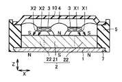
- FIG. 1 is a schematic cross-sectional view showing a configuration of a speaker unit according to Embodiment 1 of the present invention.
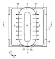
- FIG. 2 is a schematic plan view of the speaker unit shown in FIG. In FIG. 2, the diaphragm and the frame cover are not shown for easy viewing.
- FIG. 1 is a schematic sectional view taken along line II of FIG.
- the speaker unit of the present embodiment includes a yoke 1, a magnet member 2, a coil 3, a diaphragm 4, a frame 5, a frame cover 10, and a mounting portion 6. It has mainly.
- the yoke 1 has a rectangular outer shape in plan view as shown in FIG.
- the magnet member 2 is disposed in contact with the yoke 1.
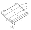
- the magnet member 2 is magnetized so that the upper surface is arranged in the order of S pole, N pole, and S pole along the X direction (one direction) in the figure, and the lower surface has N pole, S pole, and N pole. It is magnetized to line up in order.
- the magnet member 2 has, for example, a plurality of magnetic bodies 21 and 22.
- the central portion 21 (first magnetic body) of the magnet member 2 is composed of a magnet whose upper surface is N pole and whose lower surface is magnetized to S pole.
- both end portions 22 (second magnetic bodies) of the magnet member 2 are composed of magnets whose upper surface is magnetized to the S pole and whose lower surface is magnetized to the N pole.
- the magnet member 2 is disposed so that the outer sides of both end portions 22 of the magnet member 2 are in contact with the inner side of the frame 5.
- the coil 3 is arranged on the upper surface of the magnet member 2 with an interval.
- the coil 3 is a flat coil (horizontal coil) in which the number of laminated coils is greater in the width direction (X or Y direction in FIGS. 1 and 2) than in the thickness direction (Z direction in FIG. 1).
- the coil 3 is arranged so that the magnetic flux generated by the magnet member 2 crosses the coil 3.
- the linear part in the planar view of the external shape is arrange
- the magnetic flux in the direction along the upper surface of the magnet member 2 drives the coil 3.
- the magnetic flux density in the direction along the upper surface of the magnet member 2 is maximized on the boundary between the central portion 21 and both end portions 22 of the magnet member 2. Therefore, the coil 3 can be driven with the maximum magnetic flux density by arranging the linear portion of the coil 3 on the boundary between the central portion 21 and the both end portions 22 of the magnet member 2.
- a magnetic circuit is constituted by the yoke 1, the magnet member 2 and the coil 3. Magnetic fluxes X ⁇ b> 1 and X ⁇ b> 2 are guided from the N pole on the top surface of the central portion 21 of the magnet member 2 to the S pole on the top surfaces of both end portions 22 so as to pass the coil 3 on the top surface of the magnet member 2.
- the diaphragm 4 has a coil 3 attached to its lower surface.
- the diaphragm 4 is formed of a thin plate so that it can vibrate in the vertical direction (Z direction).
- the diaphragm 4 is made of, for example, a synthetic resin.
- the outer periphery of the diaphragm 4 is supported by the frame 5.
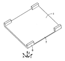
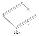
- FIG. 3 is a schematic perspective view of the yoke in the present embodiment.
- FIG. 4 is a schematic perspective view of the yoke and the magnet member in the present embodiment.
- the yoke 1 has a mounting portion 6 on a side along the direction (Y direction) intersecting the direction in which the S pole, the N pole, and the S pole are arranged on the upper surface of the magnet member 2.
- the attachment portion 6 is a portion that is supported by the frame 5 when the yoke 1 is attached to the frame 5, and rises upward from the side of the yoke 1 (Z direction) in the figure. Further, a notch portion 7 is formed at the center of the attachment portion 6.
- the central portion of the attachment portion 6 is an intermediate portion in the longitudinal direction of the attachment portion 6.
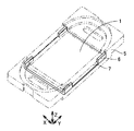
- FIG. 5 is a schematic perspective view of the yoke and the frame in the present embodiment.
- the upper surface of the outer peripheral portion of yoke 1 is covered with frame 5.
- the entire mounting portion 6 of the yoke 1 is fitted to the frame 6, and the entire surface of the mounting portion 6 is supported by the frame 5, whereby the yoke 1 is connected to the frame 5.
- the assembly of the yoke 1 and the frame 5 is performed by insert molding, for example. That is, assembly is performed by injecting resin with the yoke 1 loaded in the mold and forming the frame 5 from the resin. As a result, the frame 5 is molded so that the resin surrounds the outer peripheral end surface of the yoke 1 and the attachment portion 6. The frame 5 is formed inside the attachment portion 6 of the yoke 1.
- a frame cover 10 is arranged so as to cover the diaphragm 4.
- the frame cover 10 is formed in a trapezoidal shape toward the upper surface.
- the frame cover 10 is attached to the frame 5 with the diaphragm 4 interposed so that the upper surface of the outer peripheral portion of the diaphragm 4 and the lower surface of the outer peripheral portion of the frame cover 10 face each other.
- the speaker unit of the present embodiment is configured.
- the magnet member 2 in which magnets are arranged as the central portion 21 and the both end portions 22 of the magnet member 2 has been described.
- the magnet member 2 has a ferromagnetic body (first magnetic body) as the central portion 21.
- magnets may be arranged on both sides of the ferromagnetic body (first magnetic body) as both ends 22.
- the magnets (second magnetic bodies) on both sides of the ferromagnetic body (first magnetic body) may be composed of magnets whose upper surface is magnetized to the S pole and whose lower surface is the N pole.
- the positions of the first magnetic body and the second magnetic body may be opposite to the above configuration. That is, the central portion 21 of the magnet member 2 has a polarity such that the upper surface is the S pole and the lower surface is the N pole as the second magnetic body, and both end portions 22 are the first magnetic body and the upper surface is the N pole and the lower surface is the S pole. You may have the polarity which becomes a pole.
- the magnet member 2 is composed of a plurality of magnetic bodies.
- the magnet member 2 may be a single magnetic body having an N pole and an S pole on the upper surface.
- FIG. 6 is a schematic cross-sectional view showing the configuration of the speaker unit in the present embodiment.
- FIG. 7 is a schematic plan view of the speaker unit shown in FIG. In FIG. 7, the diaphragm and the frame cover are not shown for easy viewing.
- FIG. 6 is a schematic sectional view taken along line VI-VI in FIG.
- the magnet member 2 is made of a single magnetic body that is multipolarly magnetized. Further, the magnetic fluxes X1 and X2 are guided on the upper surface of the magnet member 2 in the same manner as the magnet member 2 having the plurality of magnetic bodies 21 and 22 described above.
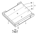
- FIG. 8 is a schematic perspective view of a magnet member made of a yoke and one magnetic body in the embodiment.
- the magnet member 2 similarly to the case where the magnet member 2 includes a plurality of magnetic bodies 21 and 22, the magnet member 2 includes a central portion 21 and both end portions 22.
- the opposite end portions 22 have opposite polarities.
- the central portion 21 has a polarity such that the upper surface is an N pole and the lower surface is an S pole
- both end portions 22 have a polarity such that the upper surface is an S pole and the lower surface is an N pole.
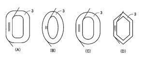
- FIGS. 9A to 9D are schematic plan views showing the shapes of the coils.
- FIG. 9A shows a rectangular coil that is rectangular in plan view and has a major axis side and a minor axis side connected in a square shape.
- the length corresponding to the linear portion of the rectangular coil can be the length of the central portion of the attachment portion 6.
- FIG. 9B shows an elliptical coil formed in an elliptical shape having a major axis and a minor axis in plan view.
- FIG. 9C shows a track-shaped coil formed in a track shape having a straight line portion in plan view. When this track-shaped coil is used as the coil 3, the length corresponding to the linear portion of the track-shaped coil can be the length of the central portion of the attachment portion 6.
- FIG. 9D shows a polygonal coil formed in a polygonal shape made up of a plurality of linear portions in plan view.
- the magnetic flux generated from the magnet member 2 is converged into the gap where the coil 3 is disposed, and a magnetic field is generated.
- the coil 3 vibrates up and down based on Fleming's left-hand rule by the current flowing through the coil 3 and the magnetic field generated from the magnet member 2. Therefore, the diaphragm 4 attached to the coil 3 vibrates. Thereby, an electric signal (current) is converted into sound (vibration).
- the yoke 1 that covers the lower surface side of the magnet member 2. Since the yoke 1 is made of, for example, a metal having high magnetic permeability, it is difficult to process it into a complicated shape by bending or the like. Therefore, the yoke 5 and the frame 5 are provided separately, and the frame 5 can be formed into a complicated shape by forming the frame 5 from, for example, resin. Moreover, the frame 5 can be reduced in weight by forming with resin. Thus, when the yoke 1 is provided separately from the frame 5, it is necessary to fix the yoke 1 to the frame 5. For this reason, it is necessary to provide the yoke 1 with a mounting portion 6 to the frame 5.
- FIG. 10 and 11 are a schematic cross-sectional view and a schematic plan view showing a configuration in which a convex attachment portion is provided as an attachment portion to the frame on the entire long side (side along the Y direction) of the yoke. .
- the diaphragm and the frame cover are not shown for easy viewing.
- FIG. 10 is a schematic sectional view taken along line XX of FIG.
- FIG. 12 is a schematic perspective view of the yoke having the configuration shown in FIGS. 10 and 11.
- FIG. 13 is a schematic perspective view of the yoke and the magnet member configured as shown in FIGS. 10 and 11.
- notch portion 7 is not formed in the central portion of attachment portion 6.
- loops of magnetic fluxes X3 and X4 that are guided to the attachment portion 6 and connect the upper surface and the lower surface of the magnet member 2 are formed on the entire long side (side along the Y direction) of the yoke.
- the magnet member 2 is magnetized so that the upper surface is aligned in the order of S pole, N pole, and S pole along the X direction, and the lower surface is aligned in order of N pole, S pole, and N pole. Magnetized. For this reason, a loop of magnetic fluxes X3 and X4 is formed that is guided to the attachment portion 6 and connects the upper surface and the lower surface of the magnet member 2.
- the notch portion 7 is provided in the central portion of the attachment portion 6 of the yoke 1.
- the magnetic fluxes X ⁇ b> 3 and X ⁇ b> 4 are not guided from the lower surface of the both end portions 22 of the magnet member 2 to the upper surface of the magnet member 2 through the yoke 1 and the attachment portion 6.
- the magnetic flux number of the upper surface of the magnet member 2 can be increased.
- the number of magnetic fluxes passing through the coil can be increased, so that the sound pressure can be improved.
- the magnetic fluxes X1 and X2 guided from the N pole on the upper surface of the magnet member 2 to the S pole cancel each other.
- the magnetic fluxes X1 and X3 cancel each other
- the magnetic fluxes X2 and X4 cancel each other, so that a loss occurs in the magnetic flux, and as a result, the magnetic efficiency in the direction along the upper surface of the magnet member 2 decreases.
- the notch 7 is provided in the center of the attachment 6 of the yoke 1.
- the magnetic fluxes X 3 and X 4 between the both end portions 22 of the magnet member 2 and the mounting portion 6 of the yoke 1 do not act effectively on the driving of the coil 3. Therefore, the attachment portion 6 of the yoke 1 may not be formed outside the both end portions 22 of the magnet member 2. .
- the cutout portion 7 can have a length corresponding to a straight portion in a plan view of the outer shape of the coil 3.
- the horizontal coil is driven mainly by a magnetic flux between the linear portion in a plan view of the outer shape of the coil 3 and the vicinity of the boundary between the N pole and the S pole on the upper surface of the magnet member 2. Therefore, the magnetic efficiency can be improved by setting the length of the cutout portion 7 to a length corresponding to the linear portion in the plan view of the outer shape of the coil 3. Thereby, a sound pressure can be improved.
- the yoke 1 and the frame 5 are assembled by insert-molding the attachment portion 6 to the frame 5. Therefore, the bonding strength between the yoke 1 and the frame 5 can be improved by forming the attachment portion 6.
- the length corresponding to the straight line portion in a plan view of the rectangular coil can be the length of the notch portion 7 of the attachment portion 6.
- the length corresponding to the straight line portion of the track-shaped coil in plan view can be the length of the notch portion 7 of the attachment portion 6.
- the magnetic flux between the round part and the attaching part 6 of the yoke 1 in a plan view of the outer shape of the coil 3 does not act effectively on the driving of the coil 3.
- the attachment portion 6 of the yoke 1 is formed in the vicinity of the round portion in a plan view of the outer shape of the coil 3, thereby preventing a decrease in magnetic efficiency.
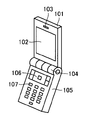
- the portable information terminal in the present embodiment is a mobile phone, and includes upper casing 101, display section 102, sound emitting hole 103, hinge section 104, lower casing 105, and operation. It mainly includes a button 106, a numeric button 107, a display unit 111, a sound emission hole 112, and a speaker unit of the first embodiment (not shown).
- a display unit 102 is provided on the surface of the upper casing 101.
- a sound emitting hole 103 is formed on one end side of the surface of the upper housing 101.
- a hinge portion 104 is formed on the other end side of the upper housing 101.
- a hinge portion 104 is formed on one end side of the lower housing 105.
- the upper housing 101 and the lower housing 105 are connected to each other by a hinge portion 104 so as to be opened and closed.
- An operation button 106 is formed on the surface of the lower housing 105 on the hinge portion 104 side.
- a numeric button 107 is formed from the operation button 106 toward the side opposite to the hinge portion 104.
- a display unit 111 is provided on the back surface of the upper housing 101.
- a sound emitting hole 112 is formed beside the display unit 111.
- the speaker unit according to the first embodiment (not shown) is provided inside the upper housing 101. Sound is emitted from the speaker unit to the outside of the portable information terminal mainly through the sound emission holes 103 and 112.
- the magnetic efficiency can be improved even if the speaker unit is reduced in size and thickness. Can be high.
- the portable information terminal in the present embodiment it is possible to make the portable information terminal smaller by making it smaller and thinner.
- the design freedom can be improved by providing a space-saving speaker unit. Further, by increasing the sound pressure, a call sound, a ring tone, etc. can be clearly recognized.
- the mobile phone has been described as the mobile information terminal.
- the mobile phone is not limited to this and may be a DSC, PDA, PC, or the like.
- the present invention can be applied particularly advantageously to a speaker unit and a portable information terminal that are reduced in size and thickness.
- FIG. 3 is a schematic cross-sectional view of the speaker unit according to Embodiment 1.
- FIG. 3 is a schematic plan view of the speaker unit according to Embodiment 1.
- FIG. 3 is a schematic perspective view of a yoke of the speaker unit according to Embodiment 1.
- FIG. 3 is a schematic perspective view of a yoke and a magnet member of the speaker unit according to Embodiment 1.
- FIG. 3 is a schematic perspective view of a yoke and a frame of the speaker unit according to Embodiment 1.
- FIG. 3 is a schematic cross-sectional view of the speaker unit according to Embodiment 1.
- FIG. 3 is a schematic plan view of the speaker unit according to Embodiment 1.
- FIG. 3 is a schematic plan view of the speaker unit according to Embodiment 1.
- FIG. 3 is a schematic perspective view of a yoke and a magnet member of the speaker unit according to Embodiment 1.
- FIG. 3 is a schematic plan view of a coil of the speaker unit according to Embodiment 1.
- FIG. It is a schematic sectional drawing of the other speaker unit for a comparison.
- It is a schematic plan view of another speaker unit for comparison.
- It is a schematic perspective view of the yoke of the other speaker unit for a comparison.
- 6 is a schematic perspective view of a portable information terminal according to Embodiment 2.
- FIG. 6 is a schematic perspective view of a portable information terminal according to Embodiment 2.
- FIG. 6 is a schematic perspective view of a portable information terminal according to Embodiment 2.
Landscapes
- Physics & Mathematics (AREA)
- Engineering & Computer Science (AREA)
- Acoustics & Sound (AREA)
- Signal Processing (AREA)
- Audible-Bandwidth Dynamoelectric Transducers Other Than Pickups (AREA)
Abstract
Description
最初に本実施の形態のスピーカユニットの構成について説明する。
状に加工することは困難である。そのため、ヨーク1とフレーム5とを別に設けて、フレーム5はたとえば樹脂で形成することによりフレーム5を複雑な形状に成形することできる。また、樹脂で形成されることによりフレーム5を軽量化することができる。このようにフレーム5とは別にヨーク1を設けた場合、ヨーク1をフレーム5に固定する必要がある。このため、ヨーク1にフレーム5への取り付け部6を設ける必要がある。
最初に本実施の形態における携帯情報端末の構成について説明する。
Claims (6)
- 平面視において矩形の外形を有するヨークと、
前記ヨーク上に配置され、かつ上面にてN極とS極とが一の方向に並ぶように着磁された磁石部材と、
前記磁石部材の前記上面上に間隔を空けて配置されたコイルと、
前記コイルに取り付けられた振動板と、
前記振動板を支持するフレームとを備え、
前記ヨークはその外周に上方へ突き出した前記フレームに前記ヨークを取り付けるための取り付け部を含み、
前記取り付け部は少なくとも前記一の方向と交差する前記取り付け部の中央部に切り欠き部を有している、スピーカユニット。 - 前記取り付け部は、前記一の方向と交差する前記取り付け部の両端部以外は切り欠き部を有している、請求項1に記載のスピーカユニット。
- 前記磁石部材は上面がN極に着磁された第1の磁性体とS極に着磁された第2の磁性体とを含む複数の磁性体よりなる、請求項1または2に記載のスピーカユニット。
- 前記磁石部材は上面にN極とS極とを有する1つの磁性体よりなる、請求項1~3のいずれかに記載のスピーカユニット。
- 前記コイルが、角形コイル、楕円形コイル、トラック形コイルおよび多角形コイルのいずれかである、請求項1~4のいずれかに記載のスピーカユニット。
- 請求項1~5のいずれかのスピーカユニットを備えた、携帯情報端末。
Priority Applications (3)
| Application Number | Priority Date | Filing Date | Title |
|---|---|---|---|
| CN200980152592.6A CN102265645B (zh) | 2008-12-25 | 2009-11-11 | 扬声器单元及携带式信息终端 |
| JP2010543977A JP5533667B2 (ja) | 2008-12-25 | 2009-11-11 | スピーカユニットおよび携帯情報端末 |
| US13/142,077 US8565471B2 (en) | 2008-12-25 | 2009-11-11 | Speaker unit and portable information terminal |
Applications Claiming Priority (2)
| Application Number | Priority Date | Filing Date | Title |
|---|---|---|---|
| JP2008331418 | 2008-12-25 | ||
| JP2008-331418 | 2008-12-25 |
Publications (1)
| Publication Number | Publication Date |
|---|---|
| WO2010073840A1 true WO2010073840A1 (ja) | 2010-07-01 |
Family
ID=42287463
Family Applications (1)
| Application Number | Title | Priority Date | Filing Date |
|---|---|---|---|
| PCT/JP2009/069206 Ceased WO2010073840A1 (ja) | 2008-12-25 | 2009-11-11 | スピーカユニットおよび携帯情報端末 |
Country Status (4)
| Country | Link |
|---|---|
| US (1) | US8565471B2 (ja) |
| JP (1) | JP5533667B2 (ja) |
| CN (1) | CN102265645B (ja) |
| WO (1) | WO2010073840A1 (ja) |
Families Citing this family (1)
| Publication number | Priority date | Publication date | Assignee | Title |
|---|---|---|---|---|
| CN206341392U (zh) * | 2016-10-25 | 2017-07-18 | 瑞声科技(新加坡)有限公司 | 扬声器 |
Citations (4)
| Publication number | Priority date | Publication date | Assignee | Title |
|---|---|---|---|---|
| JP2004072647A (ja) * | 2002-08-09 | 2004-03-04 | Foster Electric Co Ltd | 電気音響変換装置 |
| JP2004128822A (ja) * | 2002-10-01 | 2004-04-22 | Sanyo Electric Co Ltd | スピーカ装置 |
| WO2006137130A1 (ja) * | 2005-06-22 | 2006-12-28 | Mitsubishi Denki Kabushiki Kaisha | 電磁変換器 |
| JP2008177860A (ja) * | 2007-01-18 | 2008-07-31 | Mitsubishi Electric Engineering Co Ltd | 電磁変換器 |
Family Cites Families (13)
| Publication number | Priority date | Publication date | Assignee | Title |
|---|---|---|---|---|
| JPS5527721A (en) * | 1978-08-18 | 1980-02-28 | Sony Corp | Diaphragm for electroacoustic converter |
| JPH0779519B2 (ja) * | 1986-12-16 | 1995-08-23 | フオスタ−電機株式会社 | 全面駆動型スピ−カの振動板及びその製造方法 |
| JP3213521B2 (ja) | 1994-09-12 | 2001-10-02 | 三洋電機株式会社 | 電気音響変換装置 |
| JP3192372B2 (ja) * | 1996-06-10 | 2001-07-23 | 有限会社エイプロインターナショナル | 薄型電磁変換器 |
| DE60003440T2 (de) * | 1999-09-14 | 2004-04-29 | Nanonord A/S | Membranwandler |
| US6714655B2 (en) * | 2001-05-11 | 2004-03-30 | Matsushita Electric Industrial Co., Ltd. | Speaker |
| JP3896970B2 (ja) * | 2003-01-31 | 2007-03-22 | 松下電器産業株式会社 | スピーカ |
| US7412065B2 (en) * | 2003-04-09 | 2008-08-12 | Harman International Industries, Incorporated | Acoustic transducer with folded diaphragm |
| US7912239B2 (en) * | 2005-06-06 | 2011-03-22 | The Furukawa Electric Co., Ltd. | Flat speaker |
| CN101107876A (zh) * | 2005-06-22 | 2008-01-16 | 三菱电机株式会社 | 电磁变换器 |
| JP4867442B2 (ja) * | 2006-04-10 | 2012-02-01 | パナソニック株式会社 | スピーカ振動板とそれを用いたスピーカ |
| JP5359212B2 (ja) * | 2008-11-18 | 2013-12-04 | パナソニック株式会社 | スピーカ |
| WO2010073837A1 (ja) * | 2008-12-25 | 2010-07-01 | 三洋電機株式会社 | スピーカユニットおよび携帯情報端末 |
-
2009
- 2009-11-11 JP JP2010543977A patent/JP5533667B2/ja not_active Expired - Fee Related
- 2009-11-11 CN CN200980152592.6A patent/CN102265645B/zh not_active Expired - Fee Related
- 2009-11-11 WO PCT/JP2009/069206 patent/WO2010073840A1/ja not_active Ceased
- 2009-11-11 US US13/142,077 patent/US8565471B2/en not_active Expired - Fee Related
Patent Citations (4)
| Publication number | Priority date | Publication date | Assignee | Title |
|---|---|---|---|---|
| JP2004072647A (ja) * | 2002-08-09 | 2004-03-04 | Foster Electric Co Ltd | 電気音響変換装置 |
| JP2004128822A (ja) * | 2002-10-01 | 2004-04-22 | Sanyo Electric Co Ltd | スピーカ装置 |
| WO2006137130A1 (ja) * | 2005-06-22 | 2006-12-28 | Mitsubishi Denki Kabushiki Kaisha | 電磁変換器 |
| JP2008177860A (ja) * | 2007-01-18 | 2008-07-31 | Mitsubishi Electric Engineering Co Ltd | 電磁変換器 |
Also Published As
| Publication number | Publication date |
|---|---|
| CN102265645B (zh) | 2014-07-30 |
| CN102265645A (zh) | 2011-11-30 |
| US8565471B2 (en) | 2013-10-22 |
| JP5533667B2 (ja) | 2014-06-25 |
| JPWO2010073840A1 (ja) | 2012-06-14 |
| US20110255733A1 (en) | 2011-10-20 |
Similar Documents
| Publication | Publication Date | Title |
|---|---|---|
| JP5494494B2 (ja) | スピーカユニットおよび携帯情報端末 | |
| US20050220320A1 (en) | Speaker for mobile terminals and manufacturing method thereof | |
| US9035513B2 (en) | Vibrator and portable information terminal having the vibrator | |
| JP2007174233A (ja) | スピーカー装置及び携帯電話機 | |
| US8160292B2 (en) | Loudspeaker and electronic apparatus using the same | |
| US10820113B2 (en) | Speaker | |
| CN118678270B (zh) | 发声装置和电子设备 | |
| JP4603972B2 (ja) | スピーカー装置用振動板及びスピーカー装置並びに携帯電話機 | |
| US20120308070A1 (en) | Slim type speaker and magnetic circuit therefor | |
| CN118678268A (zh) | 发声装置和电子设备 | |
| JP5533667B2 (ja) | スピーカユニットおよび携帯情報端末 | |
| US20110317867A1 (en) | Speaker unit and portable information terminal | |
| US10764685B2 (en) | Speaker | |
| JP2010124091A (ja) | スピーカ | |
| JP4591017B2 (ja) | スピーカ | |
| CN222814595U (zh) | 发声装置和电子设备 | |
| CN222814594U (zh) | 发声装置和电子设备 | |
| US20250380089A1 (en) | Speaker and Speaker Box Using Same | |
| JP2008141274A (ja) | 電気音響変換器 | |
| JP2006311156A (ja) | 電気音響変換器 | |
| KR20050075787A (ko) | 스피커의 음압발생장치 및 이를 포함한 휴대단말기용 스피커 | |
| CN121418734A (zh) | 发声装置和电子设备 | |
| CN121418738A (zh) | 发声装置和电子设备 | |
| CN121418737A (zh) | 发声装置和电子设备 | |
| CN121418735A (zh) | 发声装置和电子设备 |
Legal Events
| Date | Code | Title | Description |
|---|---|---|---|
| WWE | Wipo information: entry into national phase |
Ref document number: 200980152592.6 Country of ref document: CN |
|
| 121 | Ep: the epo has been informed by wipo that ep was designated in this application |
Ref document number: 09834644 Country of ref document: EP Kind code of ref document: A1 |
|
| ENP | Entry into the national phase |
Ref document number: 2010543977 Country of ref document: JP Kind code of ref document: A |
|
| WWE | Wipo information: entry into national phase |
Ref document number: 13142077 Country of ref document: US |
|
| NENP | Non-entry into the national phase |
Ref country code: DE |
|
| 122 | Ep: pct application non-entry in european phase |
Ref document number: 09834644 Country of ref document: EP Kind code of ref document: A1 |