WO2010073786A1 - スピーカ装置 - Google Patents
スピーカ装置 Download PDFInfo
- Publication number
- WO2010073786A1 WO2010073786A1 PCT/JP2009/066624 JP2009066624W WO2010073786A1 WO 2010073786 A1 WO2010073786 A1 WO 2010073786A1 JP 2009066624 W JP2009066624 W JP 2009066624W WO 2010073786 A1 WO2010073786 A1 WO 2010073786A1
- Authority
- WO
- WIPO (PCT)
- Prior art keywords
- magnetic circuit
- vibration
- magnetic
- unit
- weight portion
- Prior art date
- Legal status (The legal status is an assumption and is not a legal conclusion. Google has not performed a legal analysis and makes no representation as to the accuracy of the status listed.)
- Ceased
Links
Images






Classifications
-
- H—ELECTRICITY
- H04—ELECTRIC COMMUNICATION TECHNIQUE
- H04R—LOUDSPEAKERS, MICROPHONES, GRAMOPHONE PICK-UPS OR LIKE ACOUSTIC ELECTROMECHANICAL TRANSDUCERS; ELECTRIC HEARING AIDS; PUBLIC ADDRESS SYSTEMS
- H04R9/00—Transducers of moving-coil, moving-strip, or moving-wire type
-
- H—ELECTRICITY
- H04—ELECTRIC COMMUNICATION TECHNIQUE
- H04R—LOUDSPEAKERS, MICROPHONES, GRAMOPHONE PICK-UPS OR LIKE ACOUSTIC ELECTROMECHANICAL TRANSDUCERS; ELECTRIC HEARING AIDS; PUBLIC ADDRESS SYSTEMS
- H04R9/00—Transducers of moving-coil, moving-strip, or moving-wire type
- H04R9/02—Details
-
- H—ELECTRICITY
- H04—ELECTRIC COMMUNICATION TECHNIQUE
- H04R—LOUDSPEAKERS, MICROPHONES, GRAMOPHONE PICK-UPS OR LIKE ACOUSTIC ELECTROMECHANICAL TRANSDUCERS; ELECTRIC HEARING AIDS; PUBLIC ADDRESS SYSTEMS
- H04R9/00—Transducers of moving-coil, moving-strip, or moving-wire type
- H04R9/06—Loudspeakers
Definitions
- the present invention relates to a speaker device that generates sound.
- the diaphragm is vibrated by the current flowing in the magnetic circuit and the voice coil from the magnetic circuit unit including the magnet, thereby generating sound.
- the magnetic circuit unit is, so to speak, vibrates the diaphragm, and is preferably installed fixedly against the vibration of the diaphragm.
- the magnetic circuit unit itself may be placed in some vibration state due to the repulsive force from the diaphragm, and the sound quality of the speaker device may deteriorate.
- Patent Document 1 a technique for suppressing the vibration of the magnetic circuit unit by additionally attaching a weight to the magnetic circuit unit. See).
- a drop in sound quality of the speaker device is suppressed by additionally fitting a bowl-shaped iron weight into the magnetic circuit portion of the speaker device.
- JP 2002-152848 A JP-A-62-38100
- metal-based materials can be cited as high-mass materials that can effectively suppress vibrations in the magnetic circuit section, but many of the metal-based materials are ferromagnetic materials. There is concern about the influence of the circuit on the magnetism.
- the present invention has been made in view of such problems, and an object of the present invention is to provide a speaker device that suppresses the vibration of the magnetic circuit unit while suppressing the magnetic influence on the magnetic circuit unit.
- the weight portion is connected via a coupling portion that couples the magnetic circuit portion and the weight portion so as to form a predetermined space that magnetically separates the magnetic circuit portion and the weight portion.
- the speaker device includes a vibration unit and generates sound by vibration of the vibration unit, and the magnetic circuit unit forms a magnetic field for vibrating the vibration unit, and is fixed to the magnetic circuit unit.
- a weight portion that suppresses vibration of the magnetic circuit portion that receives a reaction force due to vibration of the vibration portion, and the weight portion is provided between the magnetic circuit portion and the weight portion.
- the magnetic circuit unit is fixed to the magnetic circuit unit via a coupling unit that couples the magnetic circuit unit and the weight unit so that a predetermined space that magnetically separates the unit is formed.
- the above-described speaker device generates sound when the vibration unit vibrates in the magnetic field formed by the magnetic circuit unit.
- the vibration unit generates air by moving air, and also has mass, so that vibration is inevitably applied to the magnetic circuit unit that vibrates the vibration unit. become.
- the weight part is fixed to the magnetic circuit part. Is done.
- the weight portion has a mass that can resist the repulsive force that the magnetic circuit portion receives due to the vibration of the vibration portion and contribute to maintaining the sound quality of the speaker device.
- the weight portion is fixed to the magnetic circuit portion by the coupling portion, so that the vibration of the magnetic circuit portion is transmitted to the weight portion.
- the coupling portion couples the magnetic circuit portion and the weight portion in a state where a predetermined space that magnetically separates the magnetic circuit portion and the weight portion is formed therebetween.
- the weight portion is fixed to the magnetic circuit portion by such a coupling portion, so that vibration of the magnetic circuit portion can be suppressed in a state where the magnetic circuit portion and the weight portion are magnetically separated from each other. . Therefore, it is possible to suppress the vibration of the magnetic circuit part while suppressing the magnetic influence of the magnetic circuit part due to the weight part being fixed to the magnetic circuit part.
- the predetermined space is a magnetic space formed between the magnetic circuit portion and the weight portion, for example, a space that magnetically insulates the magnetic circuit portion and the weight portion.
- the vibration unit includes a coil through which an electrical audio signal flows
- the magnetic circuit unit includes a magnet unit and a yoke unit that guides the magnetic flux of the magnet unit to a space where the coil is disposed.
- the weight portion is configured to couple the magnetic circuit portion and the weight portion in a state where the coupling portion sandwiches a spacer made of a non-magnetic material between the yoke portion and the weight portion.
- the magnetic circuit unit may be fixed in a state where the predetermined space is formed.
- the reaction force transmitted from the vibrating portion to the yoke portion is transmitted to the weight portion via the spacer, and the magnetic circuit portion. Is effectively suppressed.
- the weight part since the weight part is being fixed to the magnetic circuit part via the nonmagnetic material, it is possible to suppress the vibration of the magnetic circuit part while suppressing the magnetic influence on the magnetic circuit part.
- the weight portion is moved from the magnetic circuit portion to the weight portion based on the correlation between the strength of the magnetic field formed in the space where the coil is disposed and the vibration suppression effect of the magnetic circuit portion by the weight portion.
- the spacer may be fixed to the magnetic circuit portion via the spacer in a state in which the distance between the magnetic circuit portion and the weight portion is adjusted by the length of the spacer in the direction toward the head.
- the influence of the magnetic field on the magnetic circuit unit is reduced when the weight unit is separated from the magnetic circuit unit, and the vibration is suppressed by fixing the weight unit close to the magnetic circuit unit. It is possible to make fine adjustments from the viewpoint of optimizing the sound quality of the speaker while balancing the two conflicting elements, so it is easy to cope with variations in the acoustic characteristics of each product. Can do.
- the vibration unit includes a coil through which an electrical audio signal flows
- the magnetic circuit unit includes a magnet unit and a yoke unit that guides the magnetic flux of the magnet unit to a space where the coil is disposed.
- the weight portion couples the magnetic circuit portion and the weight portion in a state where the magnetic coupling portion suppresses the magnetic flux leaking from the magnetic circuit portion between the yoke portion and the weight portion. Accordingly, the magnetic circuit unit may be fixed to the magnetic circuit unit in a state where the predetermined space is formed between the magnetic circuit unit and the weight unit.
- the yoke portion is coupled to the weight portion with the magnetic shield portion interposed therebetween, the reaction force transmitted from the vibrating portion to the yoke portion is transmitted to the weight portion via the magnetic shield portion, and magnetic The vibration of the circuit unit is effectively suppressed.
- the magnetic shield part is sandwiched between the magnetic circuit part and the weight part so that the magnetic flux of the magnetic circuit part is not affected by the weight part, the magnetic circuit is suppressed while suppressing the magnetic influence on the magnetic circuit part. It is possible to effectively suppress the vibration of the part.
- the weight portion may be coupled to the magnetic circuit portion by a screw made of a non-magnetic material.
- the magnetic circuit portion and the weight portion are firmly coupled to each other through screws, so that the vibration of the magnetic circuit portion is reliably transmitted to the weight portion, and the magnetic force to the magnetic circuit portion is increased. Can be suppressed.
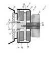
- the internal structure figure of the speaker apparatus which concerns on 1st embodiment The principal part enlarged view which expanded the magnetic circuit part of the speaker apparatus which concerns on 1st embodiment, and its peripheral part.
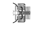
- the figure which shows the flow of the magnetic flux in case a spacer is a ferromagnetic body.
- the figure which shows the flow of the magnetic flux of the speaker apparatus which concerns on 1st embodiment The figure which shows the flow of the magnetic flux of the speaker apparatus which concerns on the modification of 1st embodiment.
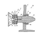
- the internal structure figure of the speaker apparatus which concerns on 2nd embodiment The principal part enlarged view which expanded the magnetic circuit part and its peripheral part of the speaker apparatus which concerns on the modification of 2nd embodiment.
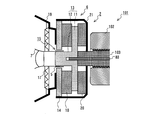
- the internal structure figure of the speaker apparatus which concerns on 3rd embodiment The principal part enlarged view which expanded the magnetic circuit part of the speaker apparatus which concerns on 3rd embodiment, and its peripheral part.
- FIG. 1 is a diagram showing an internal structure when the speaker device 1 according to the first embodiment is viewed from the right side.
- the speaker device 1 includes a speaker unit 2 that converts an electrical signal into sound, an anchor 3 (corresponding to a weight portion in the present invention) that suppresses vibration of the speaker unit 2, and a stay that supports them. 4 is provided.
- the speaker unit 2 is basically the same as a conventional general speaker, and the voice coil 5 uses the magnetic field of the magnetic circuit unit 6 to mount the diaphragm 7 (corresponding to the vibrating unit in the present invention). By vibrating, the diaphragm 7 vibrates air and makes a sound. Since the speaker unit 2 is connected to the anchor 3 on the back side, the vibration of the diaphragm 7 is transmitted to the anchor 3 as it is.
- the speaker unit 2 is connected to the stay 4 via the anchor 3, thereby supporting the speaker unit 2.
- the anchor 3 is an iron weight having a cylindrical outer shape in which one end side in the longitudinal direction is narrowed, the thin side faces the back side of the speaker device 1 and the other end connected to the speaker unit 2 faces the front side. As shown in FIG. The reason why the anchor 3 is made of iron is that it is superior to materials such as stainless steel in terms of cost and workability.
- the anchor 3 has a mass necessary for suppressing unnecessary vibration of the magnetic circuit unit 6 due to repulsive force from the diaphragm 7.
- the anchor 3 is coupled to the yoke 11 of the magnetic circuit unit 6 to be structurally integrated, thereby suppressing unnecessary vibration of the magnetic circuit unit 6.
- a flange 9 having a hole through which a fixing screw 8A for connecting to the stay 4 is inserted is provided on the outer peripheral surface of the anchor 3, and the speaker unit 2 is fixed to the central axis portion of the anchor 3.
- a hole through which a fixing screw 8B (corresponding to the connecting portion in the present invention) is inserted is provided.
- FIG. 2 is an enlarged view of a main part of the internal structure of the speaker device 1 shown in FIG.
- the speaker unit 2 includes a so-called outer magnet type magnetic circuit unit 6 having an annular main magnet 10.
- the magnetic circuit unit 6 includes a center pole 13 composed of a disk-shaped yoke 11 and a columnar pole 12 protruding from the center of the yoke 11, and an annular plate 14 that circulates around the pole 12. ing.
- An annular plate 14 that circulates around the pole 12 forms a gap 15 that is a minute gap with the pole 12.
- the main magnet 10 is disposed between the plate 14 and the yoke 11.
- the main magnet 10 is a permanent magnet.
- the center pole 13 and the plate 14 are made of ferromagnetic iron.
- the magnetic circuit unit 6 includes a main magnet 10, a yoke 11, a pole 12, a gap 15, and a plate 14, and forms a magnetic circuit that passes through these in order and returns to the main magnet 10 again.
- the main magnet 10 is arranged so that the front side of the speaker device 1 is the S pole and the back side is the N pole.
- a frame 18 that supports the diaphragm 7 is fixed to the front side of the plate 14.
- the diaphragm 7 is connected to the frame 18 via an edge 16 formed of a deformable elastic member attached to the outer peripheral side and a damper 17 attached to the inner peripheral side.
- the edge 16 and the damper 17 are connected to each other. Within a certain deformable range, it can move relative to the magnetic circuit section 6.
- the diaphragm 7 has a bobbin 19 around which the voice coil 5 is wound.
- the bobbin 19 and the voice coil 5 are inserted into the gap 15. Since the magnetic field formed by the magnetic circuit unit 6 is formed in the gap 15, a force that drives the diaphragm 7 in the front-rear direction acts when electricity flows through the voice coil 5.
- the diaphragm 7 when an electric audio signal is passed through the voice coil 5, the diaphragm 7 generates a vibration based on the waveform of the electric audio signal due to the interaction between the magnetic field of the gap 15 and the voice coil 5 through which the electric audio signal flows. .
- An annular cancel magnet 20 is arranged on the back side of the yoke 11 so that the N pole faces the front side and the S pole faces the back side.
- the cancel magnet 20 is a permanent magnet.
- the cancel magnet 20 and the magnetic circuit unit 6 are accommodated in a cylindrical shield cover 21 having one end opened so that the magnetism of the magnetic circuit unit 6 does not leak to the surroundings. Note that a hole for enabling the yoke 11 and the anchor 3 to be coupled is provided at the center of the shield cover 21.
- the speaker unit 2 is coupled to the anchor 3 via the spacer 22 and the fixing screw 8B.
- a screw hole of a fixing screw 8B is provided at the center of the back side of the yoke 11, and the spacer 22 fitted in the hole of the anchor 3 is brought into contact with the back side of the yoke 11 so that the speaker unit 2 Is coupled to the anchor 3.
- the predetermined mass is a mass that can resist the reaction force that the magnetic circuit unit 6 receives due to the vibration of the diaphragm 7 and contribute to maintaining the sound quality of the speaker device.
- the spacer 22 is formed of aluminum which is a non-magnetic material.
- the spacer 22 is formed of ferromagnetic iron or the like, a part of the magnetic flux of the magnetic circuit unit 6 reaches the anchor 3 via the spacer 22, and a magnetic field is generated around the speaker device 1. Will be formed (see FIG. 3).
- the spacer 22 is formed of aluminum which is a non-magnetic material, and the spacer 22 serves as a magnetoresistor, so that a magnetic circuit as shown in FIG. Magnetic flux does not flow from the part 6 to the anchor 3.
- a part of the magnetic flux that should originally contribute to the formation of the magnetic field of the gap 15 does not enter the anchor 3, so that the strength of the magnetic field formed in the gap 15 is not attenuated.
- a space (corresponding to a predetermined space in the present invention) is formed between the anchor 3 and the magnetic circuit portion 6 so as to magnetically separate them.
- the vibration of the magnetic circuit unit 6 and the influence on the magnetism of the magnetic circuit unit 6 are suppressed, so that high-quality sound can be reproduced.
- the magnetism leaking around the speaker device 1 is also reduced, it is possible to satisfy the magnetic-shielding standard and the like.
- aluminum is exemplified as the non-magnetic material for the spacer 22, but the present invention is not limited to such a material.
- the polarity of the main magnet 10 is arrange
- the polarity may be reverse. In this case, it is necessary to reverse the polarity of the cancel magnet 20.
- iron which is a ferromagnetic material
- the fixing screw 8B may be formed of stainless steel, which is a nonmagnetic material, like the spacer 22. If the fixing screw 8B is formed of a nonmagnetic material, it is possible to more reliably suppress the magnetism from the magnetic circuit portion 6 to the anchor 3.
- the speaker device 1 is configured by the outer magnet type magnetic circuit unit 6.
- the present invention is not limited to this, and for example, a so-called inner magnet type magnetic circuit unit. It is also possible to configure.
- the spacer 22 is made of a non-magnetic material, but the present invention is not limited to such a material.
- the spacer 22 may be formed of a magnetic material such as a permanent magnet.
- FIG. 5 is a diagram showing the flow of magnetic flux when the spacer 22 is formed of a permanent magnet.
- a permanent magnet is used for the spacer 22, and the polarity of the spacer 22 is set to be in the same direction as the polarity of the cancel magnet 20 as shown in FIG. 5. That is, the polarity of the spacer 22 is set so that the N pole faces the front side and the S pole faces the back side.
- the spacer 22 is arranged so as to prevent magnetism from leaking from the magnetic circuit unit 6, thereby providing the same operational effects as the above-described embodiment in which the spacer 22 is made of a non-magnetic material. Is possible. However, since the magnetic flux of the spacer 22 that plays the role of a cancel magnet passes through the anchor 3, the magnetic shielding performance of the speaker device 1 is slightly inferior to that of the above embodiment. However, since at least the magnetism of the magnetic circuit section 6 is prevented from entering the anchor 3, the magnetic field strength of the gap 15 can be kept sufficiently.
- FIG. 6A is a diagram showing an internal structure when the speaker device 51 according to the second embodiment is viewed from the right side.
- symbol are attached
- the speaker device 51 according to the present embodiment includes a speaker unit 2, an anchor 52 that suppresses vibration of the speaker unit 2, and a stay 4 that supports them. It has. Since the structure of the speaker unit 2 and the stay 4 is the same as that of the first embodiment described above, the description thereof is omitted.
- the anchor 52 of the speaker device 51 according to the present embodiment is not provided with a hole for fitting the spacer 22. Other points are the same as those of the anchor 3 according to the first embodiment.
- the anchor 52 and the speaker unit 2 are connected without the spacer 22 as in the speaker device 1 according to the first embodiment. Therefore, the front side of the anchor 52 is in contact with the back side of the shield cover 21 of the speaker unit 2.
- the vibration of the magnetic circuit unit 6 is transmitted to the anchor 52 via the cancel magnet 20 and the shield cover 21. Therefore, the reaction force transmitted from the diaphragm 7 to the magnetic circuit unit 6 is sufficiently canceled out by the mass of the anchor 52, and the deterioration of the sound quality of the speaker device 51 due to the vibration of the magnetic circuit unit 6 can be suppressed. Moreover, since the magnetism which goes around from the magnetic circuit part 6 to the anchor 3 is suppressed by the cancel magnet 20, attenuation of the strength of the magnetic field of the gap 15 caused by the magnetism of the magnetic circuit part 6 going around to the anchor 3 is suppressed. Therefore, according to the speaker device 51, the vibration of the magnetic circuit unit 6 and the influence on the magnetism of the magnetic circuit unit 6 are suppressed, so that high-quality sound can be reproduced.
- the material of the fixing screw 8B is preferably a nonmagnetic material such as aluminum or brass, but it is also possible to use a ferromagnetic material such as iron.
- the shield cover 21 is sandwiched between the anchor 52 and the cancel magnet 20, but the present invention is not limited to such an embodiment. That is, the anchor 52 may be in direct contact with the cancel magnet 20.
- FIG. 6A the case where the shield cover 21 and the anchor 52 are in surface contact is illustrated in FIG. 6A, but the present invention is not limited to this.
- an annular rib 53 may be provided on the shield cover 21 to reduce the contact area between the shield cover 21 and the anchor 52. Since a magnetic resistance is generated between the shield cover 21 and the anchor 52 by the rib 53, the magnetic flux leaking from the magnetic circuit unit 6 by the cancel magnet 20 is more effectively suppressed, and the magnetic field strength of the gap 15 is increased. Is possible.
- FIG. 7 is a diagram showing an internal structure when the speaker device 101 according to the third embodiment is viewed from the right side.
- symbol are attached
- the speaker device 101 according to the present embodiment includes a speaker unit 2, an anchor 102 that suppresses vibration of the speaker unit 2, and a stay 4 that supports them, as shown in FIG. 7. It has. Since the structure of the speaker unit 2 and the stay 4 is the same as that of the first embodiment described above, the description thereof is omitted.
- FIG. 8 is an enlarged view of a main part in which the magnetic circuit unit 6 and its peripheral part of the speaker device 101 according to the present embodiment are enlarged.
- the anchor 102 of the speaker device 101 according to the present embodiment is a screw hole in which the spacer 22 is fitted. Further, the anchor 102 and the speaker unit 2 are connected by a spacer 103 having a screw portion. The speaker device 101 according to the present embodiment can adjust the distance between the speaker unit 2 and the anchor 102 by rotating the spacer 103.
- the space between the speaker unit 2 and the anchor 102 is reduced, the magnetic field leaking from the magnetic circuit unit 6 to the anchor 102 increases, so that the magnetic field of the gap 15 is weakened, but the vibration of the magnetic circuit unit 6 is more effectively suppressed. .
- the distance between the speaker unit 2 and the anchor 102 is increased, the effect of suppressing the vibration of the magnetic circuit unit 6 is slightly lost, but the magnetism leaking from the magnetic circuit unit 6 to the anchor 102 is reduced, so the magnetic field of the gap 15 is reduced. Becomes stronger.
- the fixing screw 8B is removed and the speaker unit 2 is detached from the anchor 102.
- the spacer 103 is rotated to the right to be screwed into the speaker unit 2. It fixes to the anchor 102 again with the fixing screw 8B.
- the fixing screw 8B is removed and the speaker unit 2 is detached from the anchor 102, and then the spacer 103 is rotated counterclockwise so that the screw comes out. 2 is fixed to the anchor 102 again with the fixing screw 8B.
- FIG. 9 is a graph showing the correlation between the distance between the speaker unit 2 and the anchor 102 and the magnetic flux in the gap 15. As shown in FIG. 9, the speaker unit 2 and the anchor 102 contribute to the improvement of the magnetic field strength of the gap 15 as the distance between the speaker unit 2 and the anchor 102 increases, but the effect gradually decreases.
- the means for adjusting the distance between the anchor 102 and the speaker unit 2 is not limited to that realized by the spacer 103 having such a screw portion.
- a thin plate for adjusting the interval may be sandwiched between the speaker unit 2 and the anchor 102 together with the spacer 103 to adjust the interval between them, or a large number of spacers 103 of various sizes may be provided. You may prepare and select the most suitable one.
Landscapes
- Physics & Mathematics (AREA)
- Engineering & Computer Science (AREA)
- Acoustics & Sound (AREA)
- Signal Processing (AREA)
- Audible-Bandwidth Dynamoelectric Transducers Other Than Pickups (AREA)
Abstract
Description
2・・・スピーカユニット
3,52,102・・・アンカー
6・・・磁気回路部
7・・・振動板
8A,8B・・・固定ネジ
10・・・主マグネット
11・・・ヨーク
15・・・ギャップ
20・・・キャンセルマグネット
22,103・・・スペーサ
Claims (5)
- 振動部を有し、該振動部の振動により音声を生成するスピーカ装置であって、
前記振動部を振動させるための磁界を形成する磁気回路部と、
前記磁気回路部に固定され、前記振動部の振動による反力を受ける該磁気回路部の振動を抑える錘部と、を備え、
前記錘部は、前記磁気回路部と該錘部との間に該磁気回路部と該錘部とを磁気的に隔てる所定空間が形成されるように該磁気回路部と該錘部とを結合する結合部を介して、該磁気回路部に固定される、
スピーカ装置。 - 前記振動部は、電気的な音声信号が流れるコイルを有し、
前記磁気回路部は、磁石部と、前記コイルが配置される空間へ該磁石部の磁束を案内するヨーク部とを有し、
前記錘部は、前記結合部が前記ヨーク部と該錘部との間に非磁性体の材料で構成されるスペーサを挟んだ状態で該磁気回路部と該錘部とを結合することにより、前記所定空間が形成された状態で該磁気回路部に固定される、
請求項1に記載のスピーカ装置。 - 前記錘部は、前記コイルが配置される空間に形成される磁界の強度と該錘部による前記磁気回路部の振動抑制効果との相関関係に基づき、該磁気回路部から該錘部に向かう方向の前記スペーサの長さによって該磁気回路部と該錘部との間の距離が調整された状態で、該磁気回路部に固定される、
請求項2に記載のスピーカ装置。 - 前記振動部は、電気的な音声信号が流れるコイルを有し、
前記磁気回路部は、磁石部と、前記コイルが配置される空間へ該磁石部の磁束を案内するヨーク部とを有し、
前記錘部は、前記結合部が前記ヨーク部と該錘部との間に前記磁気回路部から漏れる磁束を抑える防磁部を挟んだ状態で該磁気回路部と該錘部とを結合することにより、該磁気回路部と該錘部との間に前記所定空間が形成された状態で該磁気回路部に固定される、
請求項1に記載のスピーカ装置。 - 前記錘部は、非磁性体の材料で構成されるネジによって前記磁気回路部と締結される、
請求項1から4の何れか一項に記載のスピーカ装置。
Priority Applications (2)
| Application Number | Priority Date | Filing Date | Title |
|---|---|---|---|
| GB1110830.5A GB2478481B (en) | 2008-12-25 | 2009-09-25 | Speaker device |
| US13/141,602 US8509471B2 (en) | 2008-12-25 | 2009-09-25 | Speaker device |
Applications Claiming Priority (2)
| Application Number | Priority Date | Filing Date | Title |
|---|---|---|---|
| JP2008329657A JP2010154184A (ja) | 2008-12-25 | 2008-12-25 | スピーカ装置 |
| JP2008-329657 | 2008-12-25 |
Publications (1)
| Publication Number | Publication Date |
|---|---|
| WO2010073786A1 true WO2010073786A1 (ja) | 2010-07-01 |
Family
ID=42287412
Family Applications (1)
| Application Number | Title | Priority Date | Filing Date |
|---|---|---|---|
| PCT/JP2009/066624 Ceased WO2010073786A1 (ja) | 2008-12-25 | 2009-09-25 | スピーカ装置 |
Country Status (4)
| Country | Link |
|---|---|
| US (1) | US8509471B2 (ja) |
| JP (1) | JP2010154184A (ja) |
| GB (1) | GB2478481B (ja) |
| WO (1) | WO2010073786A1 (ja) |
Citations (9)
| Publication number | Priority date | Publication date | Assignee | Title |
|---|---|---|---|---|
| JPS63283399A (ja) * | 1987-05-15 | 1988-11-21 | Matsushita Electric Ind Co Ltd | スピ−カ |
| JPH0626394U (ja) * | 1992-08-27 | 1994-04-08 | 富士通テン株式会社 | スピーカ |
| JP3008172U (ja) * | 1994-08-23 | 1995-03-07 | 三菱電機エンジニアリング株式会社 | 壁掛け型スピーカ |
| JPH11146471A (ja) * | 1997-11-13 | 1999-05-28 | Time Domain:Kk | スピーカ |
| JP2598980Y2 (ja) * | 1993-04-05 | 1999-08-23 | 富士通テン株式会社 | スピーカ |
| JP2603679Y2 (ja) * | 1993-12-28 | 2000-03-15 | 富士通テン株式会社 | スピーカ |
| JP2002152884A (ja) * | 2000-11-10 | 2002-05-24 | Fujitsu Ten Ltd | スピーカ装置 |
| JP2004015566A (ja) * | 2002-06-07 | 2004-01-15 | Fujitsu Ten Ltd | 車載用スピーカ |
| JP2005005934A (ja) * | 2003-06-11 | 2005-01-06 | Fujitsu Ten Ltd | スピーカ構造 |
Family Cites Families (5)
| Publication number | Priority date | Publication date | Assignee | Title |
|---|---|---|---|---|
| US2346429A (en) * | 1940-12-20 | 1944-04-11 | Harrison Frank | Sound reproducing and receiving device |
| US3109072A (en) * | 1960-09-26 | 1963-10-29 | Utah Radio Products Corp | Loud-speaker |
| JPS6238100A (ja) | 1985-08-13 | 1987-02-19 | Matsushita Electric Ind Co Ltd | スピ−カ |
| GB2402836B (en) * | 2003-06-09 | 2006-12-20 | Fujitsu Ten Ltd | Speaker apparatus |
| JP3981926B2 (ja) * | 2003-11-17 | 2007-09-26 | ソニー株式会社 | スピーカ装置 |
-
2008
- 2008-12-25 JP JP2008329657A patent/JP2010154184A/ja not_active Withdrawn
-
2009
- 2009-09-25 WO PCT/JP2009/066624 patent/WO2010073786A1/ja not_active Ceased
- 2009-09-25 US US13/141,602 patent/US8509471B2/en active Active
- 2009-09-25 GB GB1110830.5A patent/GB2478481B/en active Active
Patent Citations (9)
| Publication number | Priority date | Publication date | Assignee | Title |
|---|---|---|---|---|
| JPS63283399A (ja) * | 1987-05-15 | 1988-11-21 | Matsushita Electric Ind Co Ltd | スピ−カ |
| JPH0626394U (ja) * | 1992-08-27 | 1994-04-08 | 富士通テン株式会社 | スピーカ |
| JP2598980Y2 (ja) * | 1993-04-05 | 1999-08-23 | 富士通テン株式会社 | スピーカ |
| JP2603679Y2 (ja) * | 1993-12-28 | 2000-03-15 | 富士通テン株式会社 | スピーカ |
| JP3008172U (ja) * | 1994-08-23 | 1995-03-07 | 三菱電機エンジニアリング株式会社 | 壁掛け型スピーカ |
| JPH11146471A (ja) * | 1997-11-13 | 1999-05-28 | Time Domain:Kk | スピーカ |
| JP2002152884A (ja) * | 2000-11-10 | 2002-05-24 | Fujitsu Ten Ltd | スピーカ装置 |
| JP2004015566A (ja) * | 2002-06-07 | 2004-01-15 | Fujitsu Ten Ltd | 車載用スピーカ |
| JP2005005934A (ja) * | 2003-06-11 | 2005-01-06 | Fujitsu Ten Ltd | スピーカ構造 |
Also Published As
| Publication number | Publication date |
|---|---|
| US20110261991A1 (en) | 2011-10-27 |
| GB2478481B (en) | 2013-01-16 |
| US8509471B2 (en) | 2013-08-13 |
| GB201110830D0 (en) | 2011-08-10 |
| JP2010154184A (ja) | 2010-07-08 |
| GB2478481A (en) | 2011-09-07 |
Similar Documents
| Publication | Publication Date | Title |
|---|---|---|
| US7724915B2 (en) | Speaker device | |
| WO2006080405A1 (ja) | 動電型電気音響変換器および電子機器 | |
| KR101911369B1 (ko) | 양방향으로 음향을 복사할 수 있는 패널 가진형 스피커 | |
| CN106878884A (zh) | 多磁体扬声器 | |
| JP7810366B2 (ja) | スピーカ装置 | |
| US7068807B2 (en) | Speaker device | |
| US9674614B2 (en) | Speaker unit | |
| JP2007104626A (ja) | 動電型電気音響変換器および電子機器 | |
| KR101843127B1 (ko) | 패널 가진형 스피커 | |
| US7940953B2 (en) | Magnetic membrane suspension | |
| US7676053B2 (en) | Electrodynamic loudspeaker | |
| JP2022069935A (ja) | スピーカ装置 | |
| WO2010073786A1 (ja) | スピーカ装置 | |
| JP7437002B2 (ja) | 音響パネルアセンブリ | |
| JP4087878B2 (ja) | 動電型電気音響変換器および電子機器 | |
| JP4783683B2 (ja) | 動電型電気音響変換器および電子機器 | |
| JP5358069B2 (ja) | スピーカ | |
| KR102046392B1 (ko) | 음질을 향상시킨 스피커 | |
| JP2024080123A (ja) | スピーカ | |
| JPS6198098A (ja) | 動電型スピ−カ | |
| JP2000278792A (ja) | スピーカ及びスピーカ装置 | |
| JP2002010391A (ja) | スピーカ、スピーカを有する電子機器、およびスピーカにおける漏洩磁束減少方法 | |
| JPH04329800A (ja) | ホーン形ドライバー | |
| JP2005236424A (ja) | スピーカ装置 | |
| JPH11341594A (ja) | スピーカ |
Legal Events
| Date | Code | Title | Description |
|---|---|---|---|
| 121 | Ep: the epo has been informed by wipo that ep was designated in this application |
Ref document number: 09834592 Country of ref document: EP Kind code of ref document: A1 |
|
| WWE | Wipo information: entry into national phase |
Ref document number: 13141602 Country of ref document: US |
|
| ENP | Entry into the national phase |
Ref document number: 1110830 Country of ref document: GB Kind code of ref document: A Free format text: PCT FILING DATE = 20090925 |
|
| NENP | Non-entry into the national phase |
Ref country code: DE |
|
| WWE | Wipo information: entry into national phase |
Ref document number: 1110830.5 Country of ref document: GB |
|
| 122 | Ep: pct application non-entry in european phase |
Ref document number: 09834592 Country of ref document: EP Kind code of ref document: A1 |