WO2010073322A1 - 真空処理装置のデータ収集システム - Google Patents
真空処理装置のデータ収集システム Download PDFInfo
- Publication number
- WO2010073322A1 WO2010073322A1 PCT/JP2008/073443 JP2008073443W WO2010073322A1 WO 2010073322 A1 WO2010073322 A1 WO 2010073322A1 JP 2008073443 W JP2008073443 W JP 2008073443W WO 2010073322 A1 WO2010073322 A1 WO 2010073322A1
- Authority
- WO
- WIPO (PCT)
- Prior art keywords
- data
- module
- status data
- control device
- transfer
- Prior art date
- Legal status (The legal status is an assumption and is not a legal conclusion. Google has not performed a legal analysis and makes no representation as to the accuracy of the status listed.)
- Ceased
Links
Images



Classifications
-
- H—ELECTRICITY
- H10—SEMICONDUCTOR DEVICES; ELECTRIC SOLID-STATE DEVICES NOT OTHERWISE PROVIDED FOR
- H10P—GENERIC PROCESSES OR APPARATUS FOR THE MANUFACTURE OR TREATMENT OF DEVICES COVERED BY CLASS H10
- H10P72/00—Handling or holding of wafers, substrates or devices during manufacture or treatment thereof
- H10P72/06—Apparatus for monitoring, sorting, marking, testing or measuring
- H10P72/0612—Production flow monitoring, e.g. for increasing throughput
-
- G—PHYSICS
- G05—CONTROLLING; REGULATING
- G05B—CONTROL OR REGULATING SYSTEMS IN GENERAL; FUNCTIONAL ELEMENTS OF SUCH SYSTEMS; MONITORING OR TESTING ARRANGEMENTS FOR SUCH SYSTEMS OR ELEMENTS
- G05B19/00—Program-control systems
- G05B19/02—Program-control systems electric
- G05B19/418—Total factory control, i.e. centrally controlling a plurality of machines, e.g. direct or distributed numerical control [DNC], flexible manufacturing systems [FMS], integrated manufacturing systems [IMS] or computer integrated manufacturing [CIM]
- G05B19/41835—Total factory control, i.e. centrally controlling a plurality of machines, e.g. direct or distributed numerical control [DNC], flexible manufacturing systems [FMS], integrated manufacturing systems [IMS] or computer integrated manufacturing [CIM] characterised by program execution
-
- H—ELECTRICITY
- H10—SEMICONDUCTOR DEVICES; ELECTRIC SOLID-STATE DEVICES NOT OTHERWISE PROVIDED FOR
- H10P—GENERIC PROCESSES OR APPARATUS FOR THE MANUFACTURE OR TREATMENT OF DEVICES COVERED BY CLASS H10
- H10P72/00—Handling or holding of wafers, substrates or devices during manufacture or treatment thereof
- H10P72/30—Handling or holding of wafers, substrates or devices during manufacture or treatment thereof for conveying, e.g. between different workstations
- H10P72/33—Handling or holding of wafers, substrates or devices during manufacture or treatment thereof for conveying, e.g. between different workstations into and out of processing chamber
- H10P72/3304—Handling or holding of wafers, substrates or devices during manufacture or treatment thereof for conveying, e.g. between different workstations into and out of processing chamber characterised by movements or sequence of movements of transfer devices
-
- H—ELECTRICITY
- H10—SEMICONDUCTOR DEVICES; ELECTRIC SOLID-STATE DEVICES NOT OTHERWISE PROVIDED FOR
- H10P—GENERIC PROCESSES OR APPARATUS FOR THE MANUFACTURE OR TREATMENT OF DEVICES COVERED BY CLASS H10
- H10P74/00—Testing or measuring during manufacture or treatment of wafers, substrates or devices
- H10P74/23—Testing or measuring during manufacture or treatment of wafers, substrates or devices characterised by multiple measurements, corrections, marking or sorting processes
-
- Y—GENERAL TAGGING OF NEW TECHNOLOGICAL DEVELOPMENTS; GENERAL TAGGING OF CROSS-SECTIONAL TECHNOLOGIES SPANNING OVER SEVERAL SECTIONS OF THE IPC; TECHNICAL SUBJECTS COVERED BY FORMER USPC CROSS-REFERENCE ART COLLECTIONS [XRACs] AND DIGESTS
- Y02—TECHNOLOGIES OR APPLICATIONS FOR MITIGATION OR ADAPTATION AGAINST CLIMATE CHANGE
- Y02P—CLIMATE CHANGE MITIGATION TECHNOLOGIES IN THE PRODUCTION OR PROCESSING OF GOODS
- Y02P90/00—Enabling technologies with a potential contribution to greenhouse gas [GHG] emissions mitigation
- Y02P90/02—Total factory control, e.g. smart factories, flexible manufacturing systems [FMS] or integrated manufacturing systems [IMS]
Definitions
- a vacuum processing apparatus for manufacturing a semiconductor device, an electronic component, and the like has a chamber that can be evacuated, and has at least one process module for performing processing on the object to be processed under vacuum, and the object to be processed on the process module. And a transport module for supplying.
- a data collection server is connected to these modules, and state data of process modules and transfer modules is always collected. The collected status data is used for monitoring the operating status of these devices and for analyzing the cause when an abnormality occurs (see Patent Document 1).
- Data collection is performed when the data collection server sends a request for transmission to the process module or transport module by socket communication in accordance with the data collection cycle, and in response to this, the process module or transport module transmits status data. Is common. JP 2005-276935 A
- the transmission request timing of data to the first response station and the last response station is greatly different. This is because the data is requested to one module, and the data is requested to the next module in order after the data is returned from the module.
- the module transmits the current value when the transmission request is received to the data collection device, so that the sampling time in each module of the state data collected in the data collection device is also shifted. It will be.
- the network is configured in such a range that this shift does not become a problem.
- this deviation may become so large that it cannot be ignored depending on the load status of the data collection device, and there is a problem that it depends on the reliability of data collection.
- the vacuum processing apparatus comprises: A transfer module for transferring an object to be processed; A transport module controller that acquires the status data of the transport module at a first timing and transmits data including the status data; A process module that is connected to the transfer module and that processes the object to be processed transferred from the transfer module; A process module control device for acquiring state data of the process module at a second timing and transmitting data including the state data; A data collection device for collecting status data of the transfer module and the process module, At least one of the transfer module control device and the process module control device receives a status data set including the status data from the other, and in response to the transmission timing, the transfer module and the process module either acquire at that time Update state data set created by updating own state data in the received state data set with the received state data is transmitted to the data collection device.
- the transfer module control device, the process module control device, and the data collection device are loop-connected or chain-connected, and configured to transmit and receive a status data set including status data of the transfer module and the process module,
- the transfer module control device and the process module control device update the status data portion acquired by the own device in the received status data set.
- Each process so that the arrival time until the state data portion updated by the process module control device and the transport module control device reaches the data collection device is less than twice the data collection interval in the data collection device.
- the transmission cycle of the status data set of the module control device and the transport module control device is set.
- the transfer module control device and the process module control device are configured so that the status data acquisition process and the data transmission process including the status data can be executed in parallel.
- a history storage device is further provided for storing a history of state data acquired by the data collection device.
- the probability that a significant shift in the state data transmission time as a whole is extremely low.
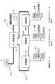
- FIG. 1 It is a figure which shows the structure of the vacuum processing apparatus of the Example of this invention. It is a figure which shows the structure of the control system containing a control apparatus and a data collection device. It is a figure which shows the structure of a control apparatus. It is a figure which shows the flow of the data between control apparatuses. It is a figure which shows the structure of a data collection device. It is a figure which shows the structural example of the vacuum processing apparatus in case there is one conveyance chamber.
- transfer robots R-1 and R-2 that can transfer an object to be processed (substrate or the like) to transfer chambers Tr-1 and Tr-2, respectively.
- the transfer chambers Tr-1 and Tr-2 are connected to an evacuation unit such as a vacuum pump (not shown) and can be evacuated. It is used for manufacturing electronic components such as semiconductor memories, magnetic memories such as MRAM, and LEDs.
- Load lock chambers LL1 and LL2 are connected to the transfer chamber Tr1.
- Each of LL1 and LL2 has a two-stage upper and lower (Upper, Lower) chamber in which wafers are placed one by one, and can be independently set to the atmosphere / vacuum. By being in the atmospheric state and the vacuum state, the wafer is unloaded and loaded from an EFEM (Equipment Front End Module) robot in the atmosphere.
- LL1 is dedicated to loading
- LL2 is dedicated to unloading.
- process modules PM-A, PM-B and PM-E are connected to the transfer chamber Tr-1.
- An aligner P1 is attached between the transfer chamber Tr1 and the transfer chamber Tr2.
- the aligner P1 moves the wafer between the transfer chambers Tr-1 and Tr-2 and corrects the position of the wafer.
- Process modules PM-I, PM-J and PM-L are connected to the transfer chamber Tr-2.
- a robot R-3 and an aligner P2 are installed in the EFEM, and the wafer is transferred between the cassette carrier on the load port (LP1 to LP4) and the load lock chamber.
- an assembly including the transfer chambers Tr-1, Tr-2, EFEM, aligner P1, and load lock chambers LL1, LL2 is the transfer module TM.
- the vacuum processing apparatus to which the present invention can be applied is not limited to the example of FIG. 1, for example, as shown in FIG. 6, the transfer chamber Tr may be one, or may be three or more.
- the number of process modules is not limited.
- a process module for forming a film by sputtering or CVD a process module for dry etching such as plasma etching, a process for heating an object to be processed for degassing or temperature adjustment. Module.
- FIG. 2 shows a control system configuration in the vacuum processing apparatus.
- the vacuum processing apparatus includes a control device 2-1 that controls the transfer module, a control device 2-2 that controls the process module PM-A, a control device 2-3 that controls the process module PM-B, and these controls.
- a data collection device 1 for collecting process module and transfer module status data from the devices 2-1 to 2-3.
- the control devices 2-1 to 2-3 and the data collection device 1 are connected to each other in a loop via the network NW1.
- the network NW1 for example, a loop connection (communication speed, for example, 10 Mbps or 25 Mbps) using an optical fiber or a coaxial cable can be applied.
- a network system such as MELSECNET / H (Mitsubishi Electric Corporation) can be used.
- PM-A, PM-B, PM-E, PM-G, PM-I, PM-J, and PM-L are shown as process modules.
- process modules PM-A and PM-B are shown for simplicity of explanation, but other process modules PM-E, G, I, J, and L are also connected in a loop to the same network NW1.
- the vacuum processing apparatus sends commands to the control devices 2-1 to 2-3 at a predetermined timing, and a host for causing the substrate processing procedure (recipe) to perform processing and the data collection device 1
- a history storage device 3 for acquiring the collected state data and storing the history, and these are connected to the data collection device 1 via the network NW2.
- the type of the network NW2 is not limited, but connection standards such as LAN and RS-232C can be applied.
- the host also has a function of outputting a data collection command to the data collection device 1.
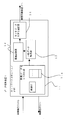
- FIG. 3 is a functional block diagram of the control device 2.
- the control device 1 is configured by a PLC (programmable logic controller), and includes a sequence unit 21, a network unit 22, and an I / O unit 23.
- PLC programmable logic controller
- the sequence unit 21 outputs an operation command to a process module to be controlled by itself or a control target device of the transfer module according to a command from the host or a predetermined sequence.
- the output value from the control target device indicating the state of the control target device and the output value of each sensor are acquired at a predetermined acquisition timing, and the status data that is the collection target of the data collection device 1 is output to the network unit 22.
- these operations are realized by repeatedly executing a predetermined sequence program (for example, every several milliseconds).
- control target device for example, as shown in FIG. 1, various types such as a gate valve GV for partitioning the process module PM and the transfer chamber TR, a mass flow controller for introducing reaction gas and discharge gas, and an exhaust valve, etc.
- the sensor include a temperature sensor for detecting the substrate temperature and the temperature in the chamber, and a pressure sensor for detecting the chamber pressure.
- the configuration method of the control device is not limited to the above.
- a plurality of process modules may be controlled by a single control device, or the transfer module may be divided for each chamber to provide a control device.
- each process module is a process module, and even if there is a pre-stage device that supplies substrates to a plurality of transfer chambers or transfer robots, a single controller is used for the transfer module involved in substrate transfer. By providing in, the expandability of the apparatus can be improved.
- the network unit 22 has a function of transmitting state data to the data collection device 1 by transmitting and receiving state data to and from the adjacent data collection device 1 or the control device 2.
- the network unit 22 includes an arithmetic processing device independent of the sequence unit 21, so that the network unit 22 can be executed in parallel with the processing by the sequence unit 21. Repeatedly performs data communication with adjacent devices at asynchronous transmission / reception intervals.
- the transmission / reception process by the network unit 22 is repeatedly executed at an interval (transmission timing) shorter than the execution (acquisition timing) interval of the sequence program for acquiring the state data.
- the network unit 22 in addition to the status data of the module to be controlled, the status data and data of all the control devices 2 connected to the same network It is possible to hold state data sets D1 to D4 including command data transmitted from the collection device 1.
- the status data of the module to be controlled can be updated by the sequence unit 21, and the status data of the other storage area holds the data received from the other control device 2 as it is, It is used with reference to the sequence unit 21 or the like.
- the data updating operation by the sequence unit 21 is performed at the sequence program execution interval (first and second timings), and the updated state data set is the next transmission timing after the data update. Is transmitted to the adjacent control device 2.
- command data included in the state data set includes a command related to a substrate processing procedure transmitted from the host via the data collection device 1 in addition to command data related to data collection transmitted from the data collection device 1.
- command data related to data collection include data specifying addition, deletion, and change of data collection items, change of acquisition cycle of some data collection items, and the like.
- the I / O unit 23 has a function of communicating with control target devices and sensors.
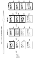
- FIG. 4 is a diagram for explaining a state data transmission / reception flow between the control devices 2-1 to 2-3 and between the control device and the data collection device 1.
- Each of the control devices 2-1 to 2-3 and the data collection device 1 receives the status data set from the adjacent control device or data collection device 1, and sends the status data set to the other adjacent control device or data collection device 1.
- a state data set held in the memory is transmitted at a predetermined transmission timing. That is, the state data set is basically propagated by one-way communication in the loop. As described above, if the status data held in each control device 2 is updated according to the status data acquisition cycle of each sequence unit 21, the updated latest status is transmitted at the next transmission timing by the network unit 22.
- a state data set including data is transmitted to the adjacent control device 2.
- the state data acquisition process, the state data update process, and the state data transmission / reception process in each of the control devices 2 and the data collection apparatus 1 are performed in accordance with a predetermined sequence program as described above regardless of whether or not the state data is updated. It is performed at an execution interval or a transmission / reception interval by the network unit.
- FIG. 4 shows a state in which each state data portion of the state data set is sequentially updated as time advances from the left side of the drawing to the right side of the drawing by such loop communication.
- the cycle in which the latest data of the control device 2 farthest from the data collection device 1 is transmitted to the data collection device 1 is regarded as the overall state data transmission cycle.
- the communication speed of the network NW1, the transmission / reception cycle of the network unit 22, and the loop configuration are set so that the transmission cycle of the network NW1 is shorter than the batch data collection cycle of the data collection device 1.
- the transmission timing such that the overall transmission cycle is smaller than twice the state data acquisition cycle (acquisition timing interval) in each control device 2
- the status data can be acquired at the same timing or different at most once.
- FIG. 5 is a functional block diagram of the data collection device 1.
- the data collection device 1 includes a network NW1-interface unit 11 that transmits and receives a state data set to and from the adjacent control device 2.
- the network NW1-interface unit 11 includes a state data set holding unit 11a.
- the state data set holding unit 11a holds and updates the state data set received from the adjacent control device 2 at a predetermined reception cycle, and transmits the state data set held here at a predetermined transmission cycle.
- the data collection device 1 includes a batch data acquisition unit 12 that acquires a state data set from the state data set holding unit of the network NW1-interface unit 11 at a predetermined batch data acquisition cycle (for example, 100 milliseconds). .
- the status data set acquired by the collective data acquisition unit 12 is added with time information at which the status data set is acquired by the history recording unit 13, and is sent to the history storage device 3 every time it is acquired or several times. To do.
- the data collection apparatus 1 is configured by providing a network interface in a general computer, for example.
- the delay caused in the data transmission time as a whole is only the processing delay of the device. Since it is extremely rare that congestion occurs in all the control devices 2 and the data collection devices 1, it is extremely rare that there is a significant shift in the transmission time of the status data as a whole, and the reliability of collected data High nature.
- the data collection device causes a delay in all the collection operations from each control device, for example, when history storage processing is congested. Become. For this reason, the overall collection time difference from the first control device to the last data collection from the last control device is very large because all delays are summed, exceeding the allowable range, and the reliability of the collected data. The property becomes insufficient.
- the present invention is not limited to this, and a chain connection in which the data collection device and one of the control devices are terminated may be performed. In this case, for example, state data is transmitted from the control device at one end to the data collection device via each control device in turn.
- the loop is duplicated, and when a failure occurs in one loop, the loop is switched to another loop. For this reason, as described above, by including the state data of all the control devices in the state data set, it is possible to restore new data when a failure occurs. It is not necessarily included in the data set. In other words, at least the downstream control device closer to the data collection device can receive the status data of all the upstream control devices, and all the control devices can receive the status data of all the control devices. It does not have to be.
Landscapes
- Engineering & Computer Science (AREA)
- Automation & Control Theory (AREA)
- General Engineering & Computer Science (AREA)
- Manufacturing & Machinery (AREA)
- Quality & Reliability (AREA)
- Physics & Mathematics (AREA)
- General Physics & Mathematics (AREA)
- Container, Conveyance, Adherence, Positioning, Of Wafer (AREA)
- Physical Vapour Deposition (AREA)
- Chemical Vapour Deposition (AREA)
- Drying Of Semiconductors (AREA)
- Programmable Controllers (AREA)
Abstract
真空処置装置における搬送モジュール及び処理モジュールの制御装置が、それらモジュールからの状態データを収集する。制御装置は、全体のモジュールについてのデータを含む状態データセットを有し、取得タイミングで取得した自己の状態データをセット中の自己の状態データについて更新して、送信タイミングでデータ収集装置に送信する。複数の制御装置がループ状又はチェーン状においてデータ収集装置と接続され、データ収集間隔よりデータ送信間隔が短く、全体の送信同期が取得タイミング間隔の2倍より小さくなるようにされている。
Description
半導体装置、電子部品などを製造する真空処理装置は、内部を排気可能なチャンバーを有し、真空下で被処理体に処理を行うための少なくとも1つのプロセスモジュールと、プロセスモジュールに被処理体を供給するための搬送モジュールと、を備えて構成される。そして、従来からこれらのモジュールに、データ収集サーバを接続し、プロセスモジュールや搬送モジュールの状態データを常時収集することが行われている。収集された状態データは、これらの装置の動作状況を監視したり、異常発生時の原因分析のために用いられたりする(特許文献1参照)。
データ収集は、データ収集周期に合わせて、データ収集サーバがプロセスモジュールや搬送モジュールにソケット通信で送信要求を行い、これに応答してプロセスモジュールや搬送モジュールが状態データを送信することにより行われるのが一般的である。
特開2005-276935号公報
データ収集は、データ収集周期に合わせて、データ収集サーバがプロセスモジュールや搬送モジュールにソケット通信で送信要求を行い、これに応答してプロセスモジュールや搬送モジュールが状態データを送信することにより行われるのが一般的である。
しかしながら、接続モジュールの数が増えると、最初の応答局と最後の応答局へのデータの送信要求タイミングが大きく異なる。
これは、1つのモジュールに対してデータを要求し、そのモジュールからデータが返信された後に順に、次のモジュールに対してデータを要求していく為である。
このように、送信要求タイミングが異なると、モジュールは送信要求を受けたときの現在値をデータ収集装置に対して送信することから、データ収集装置において収集する状態データの各モジュールにおけるサンプリング時刻もずれることになる。通常はこのずれが問題とならない範囲にネットワークを構成する。しかし、例えば、データ収集装置が輻輳している場合など、データ収集装置の負荷状況によって、このずれが無視できないほど大きくなることがあり、データ収集の信頼性にかけると言う問題があった。
これは、1つのモジュールに対してデータを要求し、そのモジュールからデータが返信された後に順に、次のモジュールに対してデータを要求していく為である。
このように、送信要求タイミングが異なると、モジュールは送信要求を受けたときの現在値をデータ収集装置に対して送信することから、データ収集装置において収集する状態データの各モジュールにおけるサンプリング時刻もずれることになる。通常はこのずれが問題とならない範囲にネットワークを構成する。しかし、例えば、データ収集装置が輻輳している場合など、データ収集装置の負荷状況によって、このずれが無視できないほど大きくなることがあり、データ収集の信頼性にかけると言う問題があった。
本発明による真空処理装置は、
被処理体を搬送する搬送モジュールと、
前記搬送モジュールの状態データを第1のタイミングで取得し、当該状態データを含むデータを送信する搬送モジュール制御装置と、
前記搬送モジュールに接続され、搬送モジュールから搬送される被処理体に処理を施すプロセスモジュールと、
前記プロセスモジュールの状態データを第2のタイミングで取得し、当該状態データを含むデータを送信するプロセスモジュール制御装置と、
前記搬送モジュール及び前記プロセスモジュールの状態データを収集するデータ収集装置と、を備え、
前記搬送モジュール制御装置及びプロセスモジュール制御装置の少なくとも一方は、他方から前記状態データを含む状態データセットを受信し、送信タイミングに応答して前記搬送モジュール及び前記プロセスモジュール一方のはその時に自己が取得している状態データで該受信した状態データセット中の自己の状態データを更新して作成された更新状態データセットを前記データ収集装置に送信することを特徴とする。
被処理体を搬送する搬送モジュールと、
前記搬送モジュールの状態データを第1のタイミングで取得し、当該状態データを含むデータを送信する搬送モジュール制御装置と、
前記搬送モジュールに接続され、搬送モジュールから搬送される被処理体に処理を施すプロセスモジュールと、
前記プロセスモジュールの状態データを第2のタイミングで取得し、当該状態データを含むデータを送信するプロセスモジュール制御装置と、
前記搬送モジュール及び前記プロセスモジュールの状態データを収集するデータ収集装置と、を備え、
前記搬送モジュール制御装置及びプロセスモジュール制御装置の少なくとも一方は、他方から前記状態データを含む状態データセットを受信し、送信タイミングに応答して前記搬送モジュール及び前記プロセスモジュール一方のはその時に自己が取得している状態データで該受信した状態データセット中の自己の状態データを更新して作成された更新状態データセットを前記データ収集装置に送信することを特徴とする。
前記搬送モジュール制御装置、プロセスモジュール制御装置及びデータ収集装置は、ループ接続又はチェーン接続されると共に、搬送モジュール及びプロセスモジュールの状態データを含む状態データセットを送受信可能に構成され、
前記搬送モジュール制御装置及びプロセスモジュール制御装置は、受信した前記状態データセットのうち、自装置で取得した状態データ部分を更新している。
前記搬送モジュール制御装置及びプロセスモジュール制御装置は、受信した前記状態データセットのうち、自装置で取得した状態データ部分を更新している。
前記プロセスモジュール制御装置及び搬送モジュール制御装置で更新した前記状態データ部分が前記データ収集装置に至るまでの到達時間が、前記データ収集装置におけるデータ収集間隔の2倍未満になるように、前記各プロセスモジュール制御装置及び搬送モジュール制御装置の状態データセットの送信周期を設定している。
前記搬送モジュール制御装置及びプロセスモジュール制御装置は、前記状態データの取得処理と、前記状態データを含むデータの送信処理と、が並行して実行可能に構成されている。
前記データ収集装置により取得した状態データの履歴を記憶する履歴記憶装置をさらに備えている。
本発明によれば、ネットワーク上の装置の1つに輻輳が発生していても、全体としての状態データの送信時間に大幅なずれが生ずる確立は極めて低くなる。
図1の真空処理装置は、搬送チャンバーTr-1、Tr-2にそれぞれ被処理体(基板等)を搬送可能な搬送ロボットR-1,R-2が存在する。搬送チャンバーTr-1、Tr-2は、図示しない真空ポンプなどの排気手段に接続されており、真空排気可能になっている。半導体メモリやMRAMなどの磁気メモリ、LEDなどの電子部品の製造に用いられる。
搬送チャンバーTr1にはロードロック室LL1、LL2が接続されている。LL1、LL2は、上下2段構造(Upper, Lower)のチャンバーでおのおの1枚ずつウェハーが入り、独立して大気・真空にすることが可能である。大気状態と真空状態になることにより、ウェハーを大気下のEFEM(Equipment Front End Module)のロボットから搬出・搬入する。LL1はロード専用、LL2はアンロード専用となっている。また、搬送チャンバーTr-1にはプロセスモジュールPM-A、PM-BとPM-Eが接続されている。搬送チャンバーTr1と搬送チャンバーTr2の間はアライナーP1が取付られている。アライナーP1は搬送チャンバーTr-1とTr-2間のウェハーの移動およびウェハーの位置補正を行っている。搬送チャンバーTr-2にはプロセスモジュールPM-I、PM-JとPM-Lが接続されている。EFEMにはロボットR-3とアライナーP2が設置され、ロードポート上(LP1~LP4)のカセットキャリア内とロードロック室内との間でウェハーを搬送する。上記図1の装置において、搬送チャンバーTr-1、Tr-2、EFEM、アライナーP1、ロードロック室LL1,LL2からなる集合体が搬送モジュールTMとなる。
なお、本発明を適用可能な真空処理装置は、図1の例に限られず、例えば、図6に示すように搬送チャンバーTrが1つのもの、あるいは、3つ以上のものであってもよく、プロセスモジュールの数も限定されない。プロセスモジュールとしては、例えば、スパッタリングやCVDにより成膜を行う成膜用のプロセスモジュール、プラズマエッチングなどのドライエッチング用のプロセスモジュール、脱ガスや温度調整の目的で被処理体を加熱するためのプロセスモジュールなどが挙げられる。
図2に、真空処理装置における制御システム構成を示す。真空処理装置は、搬送モジュールを制御する制御装置2-1と、プロセスモジュールPM-Aを制御する制御装置2-2と、プロセスモジュールPM-Bを制御する制御装置2-3と、これらの制御装置2-1~2-3からプロセスモジュール及び搬送モジュールの状態データを収集するデータ収集装置1と、を備える。
これらの制御装置2-1~2-3及びデータ収集装置1は、ネットワークNW1を介し、互いにループ接続されている。ネットワークNW1としては、例えば、光ファイバや同軸ケーブルによるループ接続(通信速度、例えば10Mbps、25Mbps)を適用でき、例えば、MELSECNET/H(三菱電機(株))などのネットワークシステムを用いることができる。
なお、図1では、プロセスモジュールとしてPM-A,PM-B,PM-E,PM-G,PM-I,PM-J,PM-Lを示している。ここでは、説明の簡単のため、プロセスモジュールPM-A,PM-Bのみ示すが、これ以外のプロセスモジュールPM-E,G,I,J,Lも同じネットワークNW1にループ接続されている。
また、真空処理装置は、制御装置2-1~2-3に所定のタイミングで指令を送り、基板の処理手順(レシピ)に従った処理を行わせるためのホストと、データ収集装置1にて収集した状態データを取得し、その履歴を記憶する履歴記憶装置3と、を備えており、これらはネットワークNW2を介してデータ収集装置1に接続されている。このネットワークNW2の種類は、限定されないが、例えば、LANやRS-232Cなどの接続規格を適用できる。なお、ホストは、データ収集装置1にデータ収集命令を出力したりする機能も有する。
図3は、制御装置2の機能ブロック図である。
制御装置1は、本実施形態ではPLC(プログラマブルロジックコントローラ)より構成され、シーケンスユニット21と、ネットワークユニット22と、I/Oユニット23と、を備える。
制御装置1は、本実施形態ではPLC(プログラマブルロジックコントローラ)より構成され、シーケンスユニット21と、ネットワークユニット22と、I/Oユニット23と、を備える。
シーケンスユニット21は、ホストからの指令又は予め定められたシーケンスに従って、自分の制御対象となるプロセスモジュールや搬送モジュールの制御対象機器に動作命令を出力する。これと共に、制御対象機器の状態を示す制御対象機器からの出力値や各センサの出力値を所定の取得タイミングで取得し、データ収集装置1が収集対象としている状態データをネットワークユニット22に出力する。本実施形態では、これらの動作は、予め定められたシーケンスプログラムを繰り返し(例えば、数ミリ秒毎)実行することで、実現する。
なお、制御対象機器としては、例えば、図1に示すようにプロセスモジュールPMと搬送チャンバーTRと間を仕切るゲートバルブGV、反応ガスや放電用ガスを導入するためのマスフローコントローラ、排気バルブなどの各種バルブ類、各プロセスモジュールのチャンバー内を真空にするためのポンプ、プラズマ生成用の電源、基板を基板載置台から昇降させるためのリフトピン、搬送モジュールTMの場合は、搬送ロボットRなどが挙げられる。また、センサとしては、基板温度やチャンバー内温度を検出するための温度センサやチャンバー圧力を検出するための圧力センサなどが挙げられる。
なお、制御装置の構成方法は上記に限定されず、例えば、複数のプロセスモジュールを1つの制御装置で制御したり、搬送モジュールを各チャンバー単位で区切って制御装置を設けるようにしてもよい。しかし、本実施形態のように、プロセスモジュールは各プロセスモジュールで、複数の搬送チャンバーや搬送ロボットに基板を供給する前段装置がある場合にも、基板搬送にかかわる搬送モジュールには制御装置を単一に設けることで、装置の拡張性を向上できる。
ネットワークユニット22は、隣接するデータ収集装置1又は制御装置2との間で状態データの送受信を行うことで、データ収集装置1に状態データを送信する機能を有する。本実施形態では、ネットワークユニット22はシーケンスユニット21とは独立した演算処理装置を備えることで、シーケンスユニット21による処理と並行して実行可能になっており、シーケンスユニット21のシーケンスプログラムの実行間隔とは非同期の送受信間隔で繰り返し隣接装置とのデータ通信を実行する。なお、本実施形態では、状態データを取得するシーケンスプログラムの実行(取得タイミング)間隔よりも短い(送信タイミング)間隔で、ネットワークユニット22による送受信処理を繰り返し実行する。
より具体的に説明すると、ネットワークユニット22は、図4に示すように、自分の制御対象となるモジュールの状態データのほか、同一のネットワークに接続する全ての制御装置2の状態データ、及び、データ収集装置1から送信される命令データを含む状態データセットD1~D4を保持可能である。このうち、自分の制御対象となるモジュールの状態データのみが、自身のシーケンスユニット21によって更新可能であり、他の記憶領域の状態データは、他の制御装置2から受信するデータをそのまま保持し、シーケンスユニット21などで参照して用いる。このシーケンスユニット21によるデータの更新動作は、上述のように、シーケンスプログラムの実行間隔(第1と第2のタイミング)で行われ、更新された状態データセットは、データ更新後の次の送信タイミングで隣接する制御装置2に送信されることとなる。
なお、状態データセットに含む命令データは、データ収集装置1から送信されるデータ収集に関する命令データのほか、ホストからデータ収集装置1を介して送信される基板の処理手順に関する命令を含む。データ収集に関する命令データとしては、例えば、データ収集項目の追加、削除、変更、一部データ収集項目の取得周期の変更などを指定するデータが挙げられる。
I/Oユニット23は、制御対象機器やセンサとの通信を行う機能を有する。図4に、制御装置2-1~2-3間及び該制御装置とデータ収集装置1間の状態データの送受信フローを説明するための図を示す。
各制御装置2-1~2-3及びデータ収集装置1は、隣接する制御装置又はデータ収集装置1から状態データセットを受信し、もう一方の隣接する制御装置又はデータ収集装置1に対し、現在メモリに保持する状態データセットを所定の送信タイミングで送信する。つまり、基本的に、ループ内の一方向の通信により、状態データセットを伝播していく。上述のように、各制御装置2で保持している状態データが、各自のシーケンスユニット21の状態データ取得周期に従って更新されれば、ネットワークユニット22による次の送信タイミングではその更新された最新の状態データを含む状態データセットが隣の制御装置2に送信される。この各制御装置2及びデータ収集装置1での状態データ取得処理、状態データの更新処理、状態データの送受信処理は、状態データが更新されたか否かにかかわらず、上述したように所定のシーケンスプログラム実行間隔や、ネットワークユニットによる送受信間隔で行われる。
図4では、このようなループ通信により、紙面左側から紙面右側に向かって時間が進むに従って、状態データセットの各状態データ部分が順に更新されていく様子を示している。本実施形態では、一方向ループにおいて、最もデータ収集装置1と離れた制御装置2の最新のデータがデータ収集装置1に送信される周期を全体としての状態データの送信周期とみなし、この全体としての送信周期がデータ収集装置1における一括データ収集周期よりも短くなるように、ネットワークNW1の通信速度やネットワークユニット22の送受信周期、ループ構成を設定している。なお、好ましくは、この全体としての送信周期が、各制御装置2における状態データ取得周期(取得タイミング間隔)の2倍よりも小さくなるように送信タイミングを設定することで、状態データセットの中の状態データはその取得タイミングが同じか、せいぜい1回異なるだけにすることができる。
図5は、データ収集装置1の機能ブロック図である。
データ収集装置1は、隣接する制御装置2との間で状態データセットを送受信するネットワークNW1-インターフェース部11を備える。ネットワークNW1-インターフェース部11は、状態データセット保持部11aを備える。この状態データセット保持部11aに、隣の制御装置2から所定の受信周期で受信した状態データセットを保持、更新し、所定の送信周期には、ここに保持される状態データセットを送信する。
データ収集装置1は、隣接する制御装置2との間で状態データセットを送受信するネットワークNW1-インターフェース部11を備える。ネットワークNW1-インターフェース部11は、状態データセット保持部11aを備える。この状態データセット保持部11aに、隣の制御装置2から所定の受信周期で受信した状態データセットを保持、更新し、所定の送信周期には、ここに保持される状態データセットを送信する。
また、データ収集装置1は、所定の一括データ取得周期(例えば、100ミリ秒)で、上記ネットワークNW1-インターフェース部11の状態データセット保持部から状態データセットを取得する一括データ取得部12を備える。一括データ取得部12により取得した状態データセットは、履歴記録部13で、状態データセットを取得した時刻情報を付加し、取得する度に又は数回取得した分をまとめて履歴記憶装置3に送信する。このように、状態データの履歴を保存することで、複数のモジュールにまたがるデバイスなどの動作を監視することができる。なお、データ収集装置1は、例えば、一般的なコンピュータにネットワークインターフェースを設けることで構成する。
本実施形態の場合、例えば、ネットワーク上の装置の1つに輻輳が発生していても、全体としてのデータの送信時間にもたらされる遅れは当該装置の処理の遅れ分だけである。全ての制御装置2及びデータ収集装置1に一度に輻輳が発生することは極めてまれであることから、全体としての状態データの送信時間に大幅なずれを生じることは極めてまれとなり、収集データの信頼性が高い。
しかし、ポーリング方式により順に制御装置2からデータを収集する方式を採用すると、データ収集装置が、例えば履歴保存処理が輻輳していた場合、各制御装置からの収集動作の全てに遅れを生じることとなる。このため、最初の制御装置から最後の制御装置からデータを収集してくるまでの全体としての収集時間差は、全ての遅れが合計されるため、非常に大きく、許容範囲を超え、収集データの信頼性が不十分となる。
なお、ループ接続した場合について述べたが、これに限らず、データ収集装置と、制御装置のうちのいずれかと、が末端となるチェーン接続を行ってもよい。この場合は、例えば、一端の制御装置から各制御装置を順に介してデータ収集装置に状態データが伝達される構成とする。
なお、ループ接続した場合について述べたが、これに限らず、データ収集装置と、制御装置のうちのいずれかと、が末端となるチェーン接続を行ってもよい。この場合は、例えば、一端の制御装置から各制御装置を順に介してデータ収集装置に状態データが伝達される構成とする。
また、上記実施形態では、図示していないがループが2重化されており、1つのループに障害が発生したときに他のループに切替えられるように構成されている。このため、上述のように、状態データセットに全ての制御装置の状態データを含めるようにすることで、障害発生時により新しいデータを復元できるようにしているが、全制御装置の状態データを状態データセットに必ずしも含めなくてもよい。つまり、少なくとも、データ収集装置により近い下流側の制御装置で、上流側の全ての制御装置の状態データを受信可能な構成とすれば、全制御装置が全制御装置の状態データを受信する構成としなくてもよい。
Claims (11)
- 被処理体を搬送する搬送モジュールと、
前記搬送モジュールの状態データを第1のタイミングで取得し、当該状態データを含むデータを送信する搬送モジュール制御装置と、
前記搬送モジュールに接続され、搬送モジュールから搬送される被処理体に処理を施すプロセスモジュールと、
前記プロセスモジュールの状態データを第2のタイミングで取得し、当該状態データを含むデータを送信するプロセスモジュール制御装置と、
前記搬送モジュール及び前記プロセスモジュールの状態データを収集するデータ収集装置と、を備え、
前記搬送モジュール制御装置及びプロセスモジュール制御装置の少なくとも一方は、他方から前記状態データを含むデータを受信し、受信タイミングに応答して前記搬送モジュール及び前記プロセスモジュールの一方はその時に自己が取得している状態データで自己の状態データを更新し他の状態データを含む状態データセットを前記データ収集装置に送信することを特徴とする真空処理装置。 - 前記搬送モジュール制御装置、プロセスモジュール制御装置及びデータ収集装置は、ループ接続されると共に、搬送モジュール及びプロセスモジュールの状態データを含む状態データセットを送受信可能に構成され、
前記搬送モジュール制御装置及びプロセスモジュール制御装置は、受信した前記状態データセットのうち、自装置で取得した状態データ部分を更新して、送信することを特徴とする請求項1に記載の真空処理装置。 - 前記プロセスモジュール制御装置及び搬送モジュール制御装置で更新した前記状態データ部分が前記データ収集装置に至るまでの到達時間が、前記データ収集装置におけるデータ収集間隔の2倍未満になるように、前記各プロセスモジュール制御装置及び搬送モジュール制御装置の状態データセットの送信周期を設定したことを特徴とする請求項2に記載の真空処理装置。
- 前記搬送モジュール制御装置及びプロセスモジュール制御装置は、前記状態データの取得処理と、前記状態データを含むデータの送信処理と、が並行して実行可能に構成されていることを特徴とする請求項1~3のいずれかに記載の真空処理装置。
- 前記データ収集装置により取得した状態データの履歴を記憶する履歴記憶装置をさらに備えることを特徴とする請求項1~4のいずれかに記載の真空処理装置。
- 前記搬送モジュールは、
搬送ロボットにより、前記プロセスモジュールに被処理体を供給する第1サブモジュールと、
前記搬送ロボットに被処理体を供給するための第2サブモジュールと、
を備え、
前記搬送モジュール制御装置は、前記第1及び第2サブモジュールに共通に設けられていることを特徴とする請求項1~5のいずれかに記載の真空処理装置。 - 被処理体を搬送する搬送モジュールの状態データを取得し、当該状態データを含むデータを送信する搬送モジュール制御装置と、
前記搬送モジュールに接続され、搬送モジュールから搬送される被処理体に処理を施すプロセスモジュールの状態データを取得し、当該状態データを含むデータを送信するプロセスモジュール制御装置と、
前記搬送モジュール及び前記プロセスモジュールの状態データを収集するデータ収集装置と、を備え、
前記搬送モジュール制御装置及びプロセスモジュール制御装置の少なくとも一方は、他方から前記状態データを含むデータの送信を受け、前記搬送モジュール及び前記プロセスモジュールの状態データを含む状態データセットを前記データ収集装置に送信することを特徴とする真空処理装置制御システム。 - 被処理体を搬送する搬送モジュールを制御する制御手段と、
前記搬送モジュールの状態データを取得する取得手段と、
前記搬送モジュールに接続され、搬送モジュールから搬送される被処理体に処理を施すプロセスモジュールの状態データを受信する受信手段と、
前記搬送モジュール及び前記プロセスモジュールの状態データを含む状態データセットを送信する送信手段と、
を備えることを特徴とする搬送モジュール制御装置。 - 被処理体を搬送する搬送モジュールの状態データを取得する取得手段と、
前記搬送モジュールに接続され、搬送モジュールから搬送される被処理体に処理を施すプロセスモジュールを制御する制御手段と、
前記プロセスモジュールの状態データを受信する受信手段と、
前記搬送モジュール及び前記プロセスモジュールの状態データを含む状態データセットを送信する送信手段と、
を備えることを特徴とするプロセスモジュール制御装置。 - 被処理体を搬送する搬送モジュールの状態データ、及び、前記搬送モジュールに接続され、搬送モジュールから搬送される被処理体に処理を施すプロセスモジュールの状態データを含む状態データセットを取得する取得手段と、
前記取得手段により取得した状態データセットに時刻情報を付加して出力する出力手段と、
を備えることを特徴とするデータ収集装置。 - 被処理体を搬送する搬送モジュールの状態データ、及び、前記搬送モジュールに接続され、搬送モジュールから搬送される被処理体に処理を施すプロセスモジュールの状態データを含む状態データセットを取得する取得手段と、
前記取得手段により取得した状態データセットに時刻情報を付加して出力する出力手段と、
を備えることを特徴とするデータ収集装置用プログラム。
Priority Applications (3)
| Application Number | Priority Date | Filing Date | Title |
|---|---|---|---|
| PCT/JP2008/073443 WO2010073322A1 (ja) | 2008-12-24 | 2008-12-24 | 真空処理装置のデータ収集システム |
| JP2010543663A JP5253517B2 (ja) | 2008-12-24 | 2008-12-24 | 真空処理装置のデータ収集システム |
| US13/165,656 US9054142B2 (en) | 2008-12-24 | 2011-06-21 | Data collection system for vacuum processing apparatus |
Applications Claiming Priority (1)
| Application Number | Priority Date | Filing Date | Title |
|---|---|---|---|
| PCT/JP2008/073443 WO2010073322A1 (ja) | 2008-12-24 | 2008-12-24 | 真空処理装置のデータ収集システム |
Related Child Applications (1)
| Application Number | Title | Priority Date | Filing Date |
|---|---|---|---|
| US13/165,656 Continuation US9054142B2 (en) | 2008-12-24 | 2011-06-21 | Data collection system for vacuum processing apparatus |
Publications (1)
| Publication Number | Publication Date |
|---|---|
| WO2010073322A1 true WO2010073322A1 (ja) | 2010-07-01 |
Family
ID=42286991
Family Applications (1)
| Application Number | Title | Priority Date | Filing Date |
|---|---|---|---|
| PCT/JP2008/073443 Ceased WO2010073322A1 (ja) | 2008-12-24 | 2008-12-24 | 真空処理装置のデータ収集システム |
Country Status (3)
| Country | Link |
|---|---|
| US (1) | US9054142B2 (ja) |
| JP (1) | JP5253517B2 (ja) |
| WO (1) | WO2010073322A1 (ja) |
Cited By (2)
| Publication number | Priority date | Publication date | Assignee | Title |
|---|---|---|---|---|
| JP2012146721A (ja) * | 2011-01-07 | 2012-08-02 | Hitachi High-Technologies Corp | 真空処理装置 |
| CN109913846A (zh) * | 2017-12-13 | 2019-06-21 | 湘潭宏大真空技术股份有限公司 | 多用途金属膜层真空镀膜生产线 |
Families Citing this family (3)
| Publication number | Priority date | Publication date | Assignee | Title |
|---|---|---|---|---|
| US8731706B2 (en) * | 2008-09-12 | 2014-05-20 | Hitachi High-Technologies Corporation | Vacuum processing apparatus |
| KR101548345B1 (ko) * | 2014-04-10 | 2015-09-01 | 피에스케이 주식회사 | 기판 처리 장치, 기판 처리 방법, 그리고 기록 매체 |
| US12512347B2 (en) * | 2021-01-07 | 2025-12-30 | Applied Materials, Inc. | Methods and apparatus for wafer detection |
Citations (3)
| Publication number | Priority date | Publication date | Assignee | Title |
|---|---|---|---|---|
| JP2002110495A (ja) * | 2000-09-26 | 2002-04-12 | Toshiba Corp | 半導体製造装置及び半導体製造装置の制御方法 |
| JP2007129177A (ja) * | 2005-10-06 | 2007-05-24 | Tokyo Electron Ltd | 処理システム |
| JP2007305632A (ja) * | 2006-05-09 | 2007-11-22 | Tokyo Electron Ltd | サーバ装置、およびプログラム |
Family Cites Families (23)
| Publication number | Priority date | Publication date | Assignee | Title |
|---|---|---|---|---|
| US4151590A (en) * | 1977-11-15 | 1979-04-24 | Hokushin Electric Works, Ltd. | Process control system |
| JP3309997B2 (ja) * | 1991-09-05 | 2002-07-29 | 株式会社日立製作所 | 複合処理装置 |
| US6301514B1 (en) * | 1996-08-23 | 2001-10-09 | Csi Technology, Inc. | Method and apparatus for configuring and synchronizing a wireless machine monitoring and communication system |
| US6002996A (en) * | 1997-11-26 | 1999-12-14 | The Johns Hopkins University | Networked sensor system |
| TW442891B (en) * | 1998-11-17 | 2001-06-23 | Tokyo Electron Ltd | Vacuum processing system |
| JP2000299367A (ja) * | 1999-04-15 | 2000-10-24 | Tokyo Electron Ltd | 処理装置及び被処理体の搬送方法 |
| TW583522B (en) * | 2001-04-27 | 2004-04-11 | Tokyo Electron Ltd | Remote maintenance system for semiconductor manufacturing apparatus and plant-side client and vendor-side server and storage medium and remote maintenance method for semiconductor manufacturing apparatus |
| US6842659B2 (en) * | 2001-08-24 | 2005-01-11 | Applied Materials Inc. | Method and apparatus for providing intra-tool monitoring and control |
| US7486693B2 (en) * | 2001-12-14 | 2009-02-03 | General Electric Company | Time slot protocol |
| US7404207B2 (en) * | 2002-03-12 | 2008-07-22 | Ils Technology, Inc. | Data sharing and networking system for integrated remote tool access, data collection, and control |
| US20040007325A1 (en) * | 2002-06-11 | 2004-01-15 | Applied Materials, Inc. | Integrated equipment set for forming a low K dielectric interconnect on a substrate |
| US7505832B2 (en) * | 2003-05-12 | 2009-03-17 | Applied Materials, Inc. | Method and apparatus for determining a substrate exchange position in a processing system |
| US7193525B2 (en) * | 2003-10-21 | 2007-03-20 | Schlumberger Technology Corporation | Methods and apparatus for downhole inter-tool communication |
| JP2005276935A (ja) | 2004-03-23 | 2005-10-06 | Hitachi Kokusai Electric Inc | 基板処理装置 |
| US7457834B2 (en) * | 2004-07-30 | 2008-11-25 | Searete, Llc | Aggregation and retrieval of network sensor data |
| US7197370B1 (en) * | 2004-10-05 | 2007-03-27 | Advanced Micro Devices, Inc. | Method and apparatus for dynamic adjustment of an active sensor list |
| US7738859B2 (en) * | 2005-03-10 | 2010-06-15 | Interdigital Technology Corporation | Multi-node communication system and method of requesting, reporting and collecting destination-node-based measurements and route-based measurements |
| WO2007035520A2 (en) * | 2005-09-15 | 2007-03-29 | Honda Motor Co., Ltd. | Interface for sensor query and control |
| US8386661B2 (en) * | 2005-11-18 | 2013-02-26 | Leviton Manufacturing Co., Inc. | Communication network for controlling devices |
| US8054752B2 (en) * | 2005-12-22 | 2011-11-08 | Intuitive Surgical Operations, Inc. | Synchronous data communication |
| US7894944B2 (en) * | 2007-07-06 | 2011-02-22 | Microsoft Corporation | Environmental monitoring in data facilities |
| JP5271525B2 (ja) * | 2007-10-04 | 2013-08-21 | 東京エレクトロン株式会社 | 基板処理装置の検査方法及び記憶媒体 |
| US7974723B2 (en) * | 2008-03-06 | 2011-07-05 | Applied Materials, Inc. | Yield prediction feedback for controlling an equipment engineering system |
-
2008
- 2008-12-24 JP JP2010543663A patent/JP5253517B2/ja active Active
- 2008-12-24 WO PCT/JP2008/073443 patent/WO2010073322A1/ja not_active Ceased
-
2011
- 2011-06-21 US US13/165,656 patent/US9054142B2/en active Active
Patent Citations (3)
| Publication number | Priority date | Publication date | Assignee | Title |
|---|---|---|---|---|
| JP2002110495A (ja) * | 2000-09-26 | 2002-04-12 | Toshiba Corp | 半導体製造装置及び半導体製造装置の制御方法 |
| JP2007129177A (ja) * | 2005-10-06 | 2007-05-24 | Tokyo Electron Ltd | 処理システム |
| JP2007305632A (ja) * | 2006-05-09 | 2007-11-22 | Tokyo Electron Ltd | サーバ装置、およびプログラム |
Cited By (2)
| Publication number | Priority date | Publication date | Assignee | Title |
|---|---|---|---|---|
| JP2012146721A (ja) * | 2011-01-07 | 2012-08-02 | Hitachi High-Technologies Corp | 真空処理装置 |
| CN109913846A (zh) * | 2017-12-13 | 2019-06-21 | 湘潭宏大真空技术股份有限公司 | 多用途金属膜层真空镀膜生产线 |
Also Published As
| Publication number | Publication date |
|---|---|
| JPWO2010073322A1 (ja) | 2012-05-31 |
| US20110313562A1 (en) | 2011-12-22 |
| US9054142B2 (en) | 2015-06-09 |
| JP5253517B2 (ja) | 2013-07-31 |
Similar Documents
| Publication | Publication Date | Title |
|---|---|---|
| JP5570775B2 (ja) | 基板処理装置のセットアップ方法、基板処理装置により実施される半導体装置の製造方法及び基板処理装置 | |
| US8571703B2 (en) | System, method and storage medium for controlling a processing system | |
| US8467895B2 (en) | Processing system and method for operating the same | |
| US10468278B2 (en) | Substrate transfer method and substrate processing apparatus | |
| JP5253517B2 (ja) | 真空処理装置のデータ収集システム | |
| KR101015228B1 (ko) | 반도체소자 제조를 위한 멀티챔버 시스템 및 그 시스템에서의 기판 처리 방법 | |
| JP5796994B2 (ja) | 処理システム、基板処理装置、処理システムのデータ処理方法、収集ユニット及び記録媒体並びに半導体装置の製造方法 | |
| CN105575853B (zh) | 基板处理系统和基板处理装置的时效方法 | |
| CN101231965A (zh) | 晶圆制造厂及其载具传输系统和方法 | |
| JP2014086487A (ja) | 基板処理システム及び基板の搬送制御方法 | |
| KR20140100894A (ko) | 반도체 장치의 제조 방법 및 기판 처리 장치 | |
| JPWO2008075404A1 (ja) | 半導体製造システム | |
| US9865488B2 (en) | Processing method and processing apparatus | |
| JP2009076495A (ja) | 真空処理装置 | |
| TWI792520B (zh) | 真空處理裝置之運轉方法 | |
| CN116210078B (zh) | 搬送方法和处理系统 | |
| JP2010027791A (ja) | 基板処理装置 | |
| KR20080079779A (ko) | 반도체소자 제조를 위한 멀티챔버 시스템 및 기판 처리 방법 | |
| JPH1116797A (ja) | 制御システム | |
| US20100168909A1 (en) | Substrate Processing Apparatus | |
| US9184073B2 (en) | Substrate processing apparatus | |
| JP5579397B2 (ja) | 真空処理装置 | |
| KR20080071680A (ko) | 기판 제조를 위한 인라인 시스템 | |
| KR20080071681A (ko) | 반도체소자 제조를 위한 멀티챔버 시스템 | |
| KR101884632B1 (ko) | 기판식각장치의 기판 식각 제어방법 |
Legal Events
| Date | Code | Title | Description |
|---|---|---|---|
| 121 | Ep: the epo has been informed by wipo that ep was designated in this application |
Ref document number: 08879118 Country of ref document: EP Kind code of ref document: A1 |
|
| DPE1 | Request for preliminary examination filed after expiration of 19th month from priority date (pct application filed from 20040101) | ||
| ENP | Entry into the national phase |
Ref document number: 2010543663 Country of ref document: JP Kind code of ref document: A |
|
| NENP | Non-entry into the national phase |
Ref country code: DE |
|
| 122 | Ep: pct application non-entry in european phase |
Ref document number: 08879118 Country of ref document: EP Kind code of ref document: A1 |