WO2010070955A1 - 照明装置、表示装置およびテレビ受信装置 - Google Patents
照明装置、表示装置およびテレビ受信装置 Download PDFInfo
- Publication number
- WO2010070955A1 WO2010070955A1 PCT/JP2009/065822 JP2009065822W WO2010070955A1 WO 2010070955 A1 WO2010070955 A1 WO 2010070955A1 JP 2009065822 W JP2009065822 W JP 2009065822W WO 2010070955 A1 WO2010070955 A1 WO 2010070955A1
- Authority
- WO
- WIPO (PCT)
- Prior art keywords
- chassis
- lamp
- lamp clip
- cushioning material
- locking
- Prior art date
- Legal status (The legal status is an assumption and is not a legal conclusion. Google has not performed a legal analysis and makes no representation as to the accuracy of the status listed.)
- Ceased
Links
Images



Classifications
-
- G—PHYSICS
- G02—OPTICS
- G02F—OPTICAL DEVICES OR ARRANGEMENTS FOR THE CONTROL OF LIGHT BY MODIFICATION OF THE OPTICAL PROPERTIES OF THE MEDIA OF THE ELEMENTS INVOLVED THEREIN; NON-LINEAR OPTICS; FREQUENCY-CHANGING OF LIGHT; OPTICAL LOGIC ELEMENTS; OPTICAL ANALOGUE/DIGITAL CONVERTERS
- G02F1/00—Devices or arrangements for the control of the intensity, colour, phase, polarisation or direction of light arriving from an independent light source, e.g. switching, gating or modulating; Non-linear optics
- G02F1/01—Devices or arrangements for the control of the intensity, colour, phase, polarisation or direction of light arriving from an independent light source, e.g. switching, gating or modulating; Non-linear optics for the control of the intensity, phase, polarisation or colour
- G02F1/13—Devices or arrangements for the control of the intensity, colour, phase, polarisation or direction of light arriving from an independent light source, e.g. switching, gating or modulating; Non-linear optics for the control of the intensity, phase, polarisation or colour based on liquid crystals, e.g. single liquid crystal display cells
- G02F1/133—Constructional arrangements; Operation of liquid crystal cells; Circuit arrangements
- G02F1/1333—Constructional arrangements; Manufacturing methods
- G02F1/1335—Structural association of cells with optical devices, e.g. polarisers or reflectors
- G02F1/1336—Illuminating devices
- G02F1/133602—Direct backlight
- G02F1/133608—Direct backlight including particular frames or supporting means
-
- G—PHYSICS
- G02—OPTICS
- G02F—OPTICAL DEVICES OR ARRANGEMENTS FOR THE CONTROL OF LIGHT BY MODIFICATION OF THE OPTICAL PROPERTIES OF THE MEDIA OF THE ELEMENTS INVOLVED THEREIN; NON-LINEAR OPTICS; FREQUENCY-CHANGING OF LIGHT; OPTICAL LOGIC ELEMENTS; OPTICAL ANALOGUE/DIGITAL CONVERTERS
- G02F1/00—Devices or arrangements for the control of the intensity, colour, phase, polarisation or direction of light arriving from an independent light source, e.g. switching, gating or modulating; Non-linear optics
- G02F1/01—Devices or arrangements for the control of the intensity, colour, phase, polarisation or direction of light arriving from an independent light source, e.g. switching, gating or modulating; Non-linear optics for the control of the intensity, phase, polarisation or colour
- G02F1/13—Devices or arrangements for the control of the intensity, colour, phase, polarisation or direction of light arriving from an independent light source, e.g. switching, gating or modulating; Non-linear optics for the control of the intensity, phase, polarisation or colour based on liquid crystals, e.g. single liquid crystal display cells
- G02F1/133—Constructional arrangements; Operation of liquid crystal cells; Circuit arrangements
- G02F1/1333—Constructional arrangements; Manufacturing methods
- G02F1/1335—Structural association of cells with optical devices, e.g. polarisers or reflectors
- G02F1/1336—Illuminating devices
- G02F1/133602—Direct backlight
- G02F1/133604—Direct backlight with lamps
Definitions
- the present invention relates to a lighting device, a display device, and a television receiver.
- a device using a display panel that does not emit light such as a liquid crystal television display device
- a backlight device as an illumination device.
- the backlight device includes a chassis and a large number of fluorescent tubes arranged on the front side (display panel side) of the chassis, and the fluorescent tubes are held by lamp clips attached to the chassis (for example, Patent Documents). 1).
- a diffusion plate that uniformly diffuses the light from the fluorescent tube is provided at a position on the display panel side of the fluorescent tube in the chassis, and a protruding pin that protrudes toward the diffusion plate is provided on the lamp clip. .
- the protruding pins support the diffusion plate from the fluorescent tube side, so that the deflection and warpage of the diffusion plate to the fluorescent tube side are regulated. JP 2008-288047 A
- the present invention has been completed based on the above circumstances, and an object thereof is to provide an illumination device, a display device, and a television receiver capable of preventing deterioration in quality.
- the illumination device includes a lamp, a chassis in which the lamp is disposed, an optical member disposed at a position sandwiching the lamp with respect to the chassis, and attached to the chassis to hold the lamp. And a lamp clip having a projecting pin projecting toward the optical member, and a cushioning material interposed between the lamp clip and the chassis. According to such a configuration, the vibration of the lamp clip is absorbed by the buffer material. Therefore, it is possible to suppress the squeaking noise as compared with the case where the lamp clip and the chassis directly rub against each other, and it is possible to prevent the quality from being deteriorated.
- the lamp clip includes a locking portion that is locked to the chassis from a side opposite to the lamp, and a base portion that sandwiches the chassis between the locking portion and the cushioning material. May be interposed at least between the base portion and the chassis.
- the lamp clip has a locking portion that locks the chassis from the opposite side of the lamp, and the cushioning material is interposed between at least the locking portion and the chassis. It may be a thing.
- the said buffer material is good also as what consists of a resin material whose heat conductivity is lower than the said lamp clip. According to such a configuration, it is difficult for the heat of the lamp to escape from the lamp clip to the chassis through the buffer material.
- the cushioning material may be a foam.
- the lamp clip includes a locking portion that locks the chassis from a side opposite to the lamp.
- the chassis includes an insertion hole into which the locking portion is inserted, and the buffer
- the material may be arranged at a position facing the insertion hole and exhibit a black color. According to such a configuration, since the buffer material absorbs light, it is possible to make it difficult for the light of the lamp to leak from the insertion hole of the chassis. Further, the cushioning material may be bonded to the lamp clip. The cushioning material may be bonded to the chassis.
- the display device of the present invention includes the illumination device and a display panel that performs display using light from the illumination device.
- the display panel may be a liquid crystal panel using liquid crystal.
- the television receiver of the present invention includes the display device.
- the invention's effect ADVANTAGE OF THE INVENTION
- the illuminating device, display apparatus, and television receiver which can prevent the deterioration of quality can be provided.
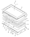
- FIG. 1 is an exploded perspective view showing a schematic configuration of a television receiver according to Embodiment 1.
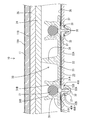
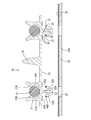
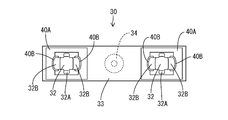
- FIG. Exploded perspective view showing schematic configuration of liquid crystal display device Partial enlarged sectional view of a liquid crystal display device Partial expanded sectional view which shows the state before a lamp clip is attached to a chassis
- TV TV receiver
- 10 Liquid crystal display device (display device)
- 11 Liquid crystal panel (display panel)
- 20 Backlight device (illumination device)
- 21 ... Discharge tube (lamp)
- 22 ... Chassis
- 24 ... Diffusion Plate (optical member)
- 27 ... insertion hole
- 30 lamp clip, 32 ... locking part, 33 ... base part, 34 ... protruding pin, 40, 50, 60 ... cushioning material
- the television receiver TV including the liquid crystal display device 10 (display device) is illustrated.
- the television receiver TV includes a liquid crystal display device 10, cabinets Ca and Cb that accommodate the liquid crystal display device 10 sandwiched from the front and back, a power source P, a tuner T for receiving television broadcasts, and the like. And a stand S.
- the liquid crystal display device 10 is housed in the cabinets Ca and Cb in a vertically placed posture with the display surface oriented in a substantially vertical direction.
- the liquid crystal display device 10 has a horizontally long rectangular shape when viewed from the front and back directions, and irradiates light toward the liquid crystal panel 11 (corresponding to the display panel of the present invention) capable of displaying an image and the liquid crystal panel 11. It has a backlight device 20 (corresponding to the illumination device of the present invention) which is an external light source, and these are integrally held by a holding member such as a bezel 12.
- the liquid crystal panel 11 includes a pair of transparent (translucent) glass substrates having a horizontally long rectangular shape, and a liquid crystal layer that is interposed between both substrates, and whose optical characteristics change with voltage application (see FIG. Not shown). Note that polarizing plates 11A and 11B are attached to the front and back surfaces of the liquid crystal panel 11 (see FIG. 3).
- the liquid crystal panel 11 is fixed with a peripheral portion sandwiched between a bezel 12 arranged on the front side and a frame 13 arranged on the back side.
- the bezel 12 and the frame 13 are made of metal (for example, aluminum), and both have a horizontally long frame shape along the peripheral edge of the liquid crystal panel 11 (surrounding the display area of the liquid crystal panel 11).
- the backlight device 20 is a so-called direct-type backlight device 20 and is provided immediately below the back surface of the liquid crystal panel 11.
- the backlight device 20 includes a chassis 22 in which a discharge tube 21 (corresponding to the lamp of the present invention) is arranged on the front side.
- the chassis 22 is made of metal, and includes a bottom plate 22A having a flat plate shape and a side plate 22B rising from the periphery of the bottom plate 22A to the front side, and has a shallow dish shape that opens to the front side as a whole.
- the bottom plate 22A has a horizontally long rectangular shape that is slightly larger than the liquid crystal panel 11 in plan view.
- the chassis 22, the bezel 12 and the frame 13 are fixed to each other by screws (not shown).
- An inverter board 23 that controls the driving of the discharge tube 21 is attached to the rear surface of the chassis 22.
- a diffusion plate 24 (corresponding to the optical member of the present invention) is disposed in the opening of the chassis 22 (position where the discharge tube 21 is sandwiched with respect to the chassis 22).
- the diffusion plate 24 is obtained by dispersing and mixing light scattering particles in a synthetic resin plate-like member, and has a function of diffusing light from the discharge tube 21 that is a linear light source.
- An optical sheet 25 is provided on the front side of the diffusion plate 24.
- the optical sheet 25 is formed by laminating a plurality of sheets having different functions. For example, a diffusion sheet, a lens sheet, and a reflective polarizing plate are sequentially formed from the back side.
- the optical sheet 25 has a function of converting light emitted from the discharge tube 21 and transmitted through the diffusion plate 24 into planar light.
- Both the diffusion plate 24 and the optical sheet 25 have a horizontally long rectangular shape, and the peripheral edge thereof is sandwiched and held between the frame 13 and a side plate 22B of the chassis 22 or a holder 28 described later.
- a reflection sheet 26 is laid that reflects light from the discharge tube 21 to the front side (the diffuser plate 24 side).
- the reflection sheet 26 is made of synthetic resin, and the surface thereof is white with excellent reflectivity.
- the reflection sheet 26 has a horizontally long rectangular shape covering substantially the entire area along the surface (inner surface) of the bottom plate 22A of the chassis 22. Yes.
- the bottom plate 22A of the chassis 22 and the reflection sheet 26 are provided with an insertion hole 27 into which a locking portion 32 of a lamp clip 30 described later is inserted.
- the insertion hole 27 is formed at the attachment position of the lamp clip 30 on the bottom plate 22A and the reflection sheet 26 of the chassis 22, and has a rectangular shape and penetrates the reflection sheet 26 and the bottom plate 22A in the front and back direction.
- a plurality of discharge tubes 21 (cold cathode tubes in the present embodiment) for irradiating light toward the liquid crystal panel 11 are accommodated in the chassis 22 (portion surrounded by the bottom plate 22A and the side plates 22B).
- the discharge tube 21 has an elongated tubular shape, and each axis is arranged in parallel at a predetermined interval in a direction that coincides with the longitudinal direction of the chassis 22. Both ends of the discharge tube 21 (non-light emitting portions where electrodes are installed) are covered with a holder 28, and an intermediate portion is held by a lamp clip 30 described later.
- the holder 28 is made of a synthetic resin having a white color with excellent light reflectivity, and has a long and narrow box shape along an edge extending in the short direction of the peripheral edge of the chassis 22.
- the backlight device 20 has a plurality of lamp clips 30 that hold the discharge tube 21.
- the lamp clip 30 is made of synthetic resin (for example, made of polycarbonate), and the surface thereof is white with excellent light reflectivity.
- the lamp clip 30 includes a lamp gripping portion 31 that grips the discharge tube 21, a locking portion 32 that is inserted into the insertion hole 27 and locks to the chassis 22 from the back (front in the insertion direction), and a locking portion 32.
- a base portion 33 is interposed between the chassis 22 and the reflection sheet 26 (see FIG. 3).
- the base portion 33 has an elongated, substantially rectangular plate shape, and a projecting pin 34 that projects toward the diffusion plate 24 is provided at the center position (substantially the center position in the longitudinal direction and the short direction).
- the protruding pin 34 has a substantially conical shape whose diameter is gradually reduced toward the protruding end, and the protruding dimension is larger than the protruding dimension of the lamp gripping portion 31.
- the protruding pins 34 support the diffusion plate 24 from the back side, so that bending or warping of the diffusion plate 24 toward the back side (discharge tube 21 side) is regulated.
- a pair of lamp gripping portions 31 is provided at both ends in the longitudinal direction of the base portion 33, and the interval between the pair of lamp gripping portions 31 matches the parallel pitch of the discharge tubes 21.
- Each lamp gripping portion 31 has a pair of arm portions 31A that sandwich the discharge tube 21, and has a substantially annular shape that opens to the front as a whole.
- the pair of arm portions 31A rises in a cantilevered manner from the base portion 33 to the front side and can be elastically deformed in the approaching / separating direction.
- the lamp gripping portion 31 is provided so that the facing direction of the pair of arm portions 31 ⁇ / b> A coincides with the longitudinal direction of the base portion 33.
- the arm portion 31A is curved in a substantially arc shape.
- a pair of holding projections 31B projecting inward are provided at positions closer to the tips of the pair of arm portions 31A, and the pair of holding projections 31B are substantially half on the front side of the discharge tube 21 gripped by the lamp gripping portion 31. It comes to contact the part.
- the locking portions 32 are provided as a pair on the back surface of the base portion 33 and at both ends in the longitudinal direction of the base portion 33 (positions directly behind the pair of lamp gripping portions 31).
- the locking portion 32 includes a base portion 32A that protrudes from the base portion 33 to the back side, and a pair of locking legs 32B that are folded back from the tip of the base portion 32A toward the base portion 33 and are disposed to face the side of the base portion 32A. have.
- the base portion 32A has a prismatic shape protruding substantially perpendicularly from the back surface of the base portion 33, and its cross-sectional shape is a substantially rectangular shape that is long in the short direction of the base portion 33 (see FIG. 5).
- the axial direction dimension (front and back direction dimension) of the base portion 32A is larger than the dimension obtained by adding the thickness dimension of the chassis 22 and the thickness dimension of the reflection sheet 26, and is substantially half when the lamp clip 30 is attached to the chassis 22. Is projected to the rear side of the chassis 22 (see FIG. 3). Note that the base portion 32A is located at the center in the facing direction of the pair of arm portions 31A of the lamp gripping portion 31.
- the pair of locking legs 32B is cantilevered from the protruding end (back side end) of the base portion 32A and extends to the front side.
- the locking leg 32B has an oblique posture that gradually moves away from the base portion 32A from the connecting end with the base portion 32A toward the free end side, and can be elastically deformed in the approaching / separating direction with respect to the base portion 32A with the connecting end as a fulcrum. ing.
- the width dimension of the locking leg 32B (the width dimension in the direction along the short side direction of the base portion 33) is slightly smaller than the width dimension of the base portion 32A in the same direction, and is substantially constant from the connecting end to the free end ( (See FIG. 5).
- a locking surface 35 that locks to the back surface of the chassis 22 is formed at the tip (free end) of the locking leg 32B.
- the locking surface 35 is substantially parallel to the back surface of the base portion 33, and between the locking surface 35 and the base portion 33, the thickness dimension of the chassis 22 and the reflection sheet 26 are in the natural state of the locking legs 32 ⁇ / b> B.
- a dimension slightly larger than the dimension obtained by adding the thickness dimension is opened.
- an entry portion 36 that enters the insertion hole 27 is provided at the distal end portion of the locking leg 32B.
- the entry portion 36 protrudes to the front side of the locking surface 35, and the surface of the entry portion 36 on the locking surface 35 side (the side opposite to the base portion 32A) rises substantially vertically from the locking surface 35. 37.
- the entry surface 37 is arranged to face the peripheral surface of the insertion hole 27. All the lamp clips 30 are dispersed in the middle portion of the chassis 22 in the longitudinal direction so that the longitudinal direction of the base portion 33 coincides with the parallel direction of the discharge tubes 21 (substantially orthogonal to the axial direction of the discharge tubes 21). It is attached.
- the buffer material 40 is interposed between the lamp clip 30 and the chassis 22 (reflection sheet 26).
- the buffer material 40 is made of a black resin (polyurethane in the present embodiment) having a lower thermal conductivity than the lamp clip 30 and has a black surface.
- the cushioning material 40 has a sheet shape, and includes a first cushioning material 40 ⁇ / b> A interposed between the base portion 33 and the chassis 22, and a second cushioning material 40 ⁇ / b> B interposed between the locking portion 32 and the chassis 22. ing.
- the thickness dimension of the buffer material 40 is substantially constant throughout.
- the first buffer material 40A and the second buffer material 40B are provided for each locking portion 32, and are bonded to the lamp clip 30 with an adhesive (not shown). Note that the first cushioning material 40A and the second cushioning material 40B are separated.
- the first buffer material 40A is bonded to the back surface of the base portion 33.
- the first cushioning material 40A has a substantially rectangular frame shape that surrounds the entire circumference of the insertion hole 27, and is affixed to a position surrounding the base portion 32A of each locking portion 32 on the back surface of the base portion 33. It is located at the approximate center of the first buffer material 40A (see FIG. 5).
- the part which opposes the longitudinal direction of the base part 33 among 40 A of 1st buffer materials is each located in the back side of the arm part 31A of the lamp
- the second cushioning material 40B is bonded to the entry surface 37 and the locking surface 35 of the tip ends of the pair of locking legs 32B.
- Each of the second buffer materials 40B has a shape bent in an L-shaped cross section along the entire surface of the entry surface 37 and the locking surface 35.
- each lamp clip 30 is grasped by a fingertip, and the pair of locking portions 32 are positioned so as to face the insertion holes 27, respectively, and the lamp clip 30 is brought closer to the chassis 22 side. Then, the pair of locking legs 32B of each locking portion 32 abuts against the hole edge of the insertion hole 27 and elastically deforms in a direction approaching the base portion 32A, and each locking portion 32 is inserted into the insertion hole 27. . As soon as the locking surface 35 of each locking portion 32 reaches the back side of the chassis 22, each locking leg 32 ⁇ / b> B elastically recovers and the locking surface 35 locks to the back surface of the chassis 22 and the entry portion 36.
- the entry surface 37 approaches the peripheral surface of the insertion hole 27.
- the portion of the second cushioning material 40B that is affixed to the locking surface 35 is sandwiched between the back surface of the chassis 22 (the back surface of the hole edge portion of the insertion hole 27) and the locking surface 35, and the chassis.
- the portion attached to the entry surface 37 is in contact with the chassis 22 by being sandwiched between the peripheral surface of the insertion hole 27 and the entry surface 37.
- the first buffer material 40 ⁇ / b> A is sandwiched between the base portion 33 and the bottom plate 22 ⁇ / b> A (reflective sheet 26) of the chassis 22 and comes into contact with the chassis 22.
- the lamp clip 30 is attached to the chassis 22 with the first cushioning material 40 ⁇ / b> A and the second cushioning material 40 ⁇ / b> B interposed between the lamp clip 30 and the chassis 22.
- the backlight device 20 of the present embodiment has the buffer material 40 interposed between the lamp clip 30 and the chassis 22, and therefore the vibration of the lamp clip 30 is absorbed by the buffer material 40. Therefore, the lamp clip 30 and the chassis 22 can be prevented from directly rubbing to generate a squeaking noise, so that deterioration in quality can be prevented.
- the buffer material 40 is made of a resin material having a lower thermal conductivity than the lamp clip 30. This makes it difficult for the heat of the discharge tube 21 to escape from the lamp clip 30 through the cushioning material 40 to the chassis 22.
- the portion of the discharge tube 21 held by the lamp clip 30 becomes lower in temperature than the other portions. , There is a possibility that the luminance of the portion is lowered and unevenness occurs.
- the buffer material 40 shall be black. Thereby, since the buffer material 40 absorbs light, the light of the discharge tube 21 can be made difficult to leak from the insertion hole 27.
- the cushioning material 50 is integrally provided with a portion interposed between the base portion 33 and the chassis 22 and a portion interposed between the locking portion 32 and the chassis 22.
- symbol is attached
- the television receiver TV according to the present embodiment includes a backlight device 20 and a liquid crystal display device 10 that includes a liquid crystal panel 11 that performs display using light from the backlight device 20. Prepare.
- the backlight device 20 includes a chassis 22 in which the discharge tube 21 is disposed on the front side, a diffusion plate 24 disposed in a position sandwiching the discharge tube 21 with respect to the chassis 22, and a diffusion plate 24. And a lamp clip 30 that is attached to the chassis 22 and holds the discharge tube 21.
- the buffer material 50 is interposed between the lamp clip 30 and the chassis 22 (reflective sheet 26) as in the first embodiment.
- the buffer material 50 has a lower thermal conductivity than the lamp clip 30 and has a black surface as in the first embodiment.
- the cushioning material 50 has a sheet shape integrally including a portion interposed between the base portion 33 and the chassis 22 and a portion interposed between the locking portion 32 and the chassis 22.
- the buffer material 50 is provided for each of the locking portions 32 and is bonded to the lamp clip 30 with an adhesive (not shown).
- the cushioning material 50 is configured to continuously cover the portion around each locking portion 32 from the outer surface of each locking portion 32 to the back surface of the base portion 33.
- the part which follows the back surface of the base part 33 among the buffer materials 50 is called 1st buffer part 50A, and the part which follows the outer surface of the latching
- the outer shape of the first buffer portion 50A is a substantially rectangular shape that is slightly larger than the insertion hole 27.
- the first buffer 50A is attached so as to cover the projection portion of the lamp gripper 31 with respect to the base 33.
- the second buffer part 50B is provided in the approximate center of the first buffer part 50A.
- the second buffer portion 50B is affixed to the outer surface of the locking portion 32 (the entire surface excluding the opposing surfaces of the pair of locking legs 32B and the base portion 32A).
- the second buffer portion 50B is a surface opposite to the entry surface 37, the locking surface 35, and the base portion 32A of the pair of locking legs 32B (contact surface with the hole edge of the insertion hole 27 during the mounting operation).
- the portion between the first buffer portion 50A and the second buffer portion 50B is a third buffer portion 50C arranged along the peripheral surface of the insertion hole 27.
- the third buffer portion 50C is substantially perpendicular to the first buffer portion 50A, and has a shape that rises from the portion along the entry surface 37 to the front side along the surface direction of the second buffer portion 50B.
- the first buffer portion 50 ⁇ / b> A is sandwiched between the base portion 33 and the bottom plate 22 ⁇ / b> A (reflective sheet 26) of the chassis 22 and is in contact with the chassis 22.
- the portion of the buffer portion 50B attached to the locking surface 35 is sandwiched between the back surface of the chassis 22 (the back surface of the hole edge of the insertion hole 27) and the locking surface 35 and is in contact with the chassis 22
- the portion attached to the entry surface 37 is sandwiched between the peripheral surface of the insertion hole 27 and the entry surface 37 and is in contact with the chassis 22.
- the third buffer portion 50 ⁇ / b> C is arranged along the peripheral surface of the insertion hole 27.
- the vibration of the lamp clip 30 is absorbed by the cushioning material 50, and the squeaking noise is generated as compared with the case where the lamp clip 30 and the chassis 22 rub against each other directly. Since it can suppress, the fall of quality can be prevented.
- the cushioning material 60 includes a portion interposed between the base portion 33 and the chassis 22 and a portion interposed between the locking portion 32 and the chassis 22. It differs from Embodiment 1 by the point which is provided over the stop part 32 integrally.
- symbol is attached
- the television receiver TV according to the present embodiment includes a backlight device 20 and a liquid crystal display device 10 that includes a liquid crystal panel 11 that performs display using light from the backlight device 20. Prepare.
- the backlight device 20 includes a chassis 22 in which the discharge tube 21 is disposed on the front side, a diffusion plate 24 disposed in a position sandwiching the discharge tube 21 with respect to the chassis 22, and a diffusion plate 24. And a lamp clip 30 that is attached to the chassis 22 and holds the discharge tube 21.
- the buffer material 60 is interposed between the lamp clip 30 and the chassis 22 (reflective sheet 26) as in the first embodiment.
- the buffer material 60 has a lower thermal conductivity than the lamp clip 30 and has a black surface.
- the cushioning material 60 integrally includes a portion interposed between the base portion 33 and the chassis 22 and a portion interposed between the locking portion 32 and the chassis 22 over the pair of locking portions 32.
- a sheet shape covering substantially the entire rear side of the lamp clip 30 is formed.
- the buffer material 60 is bonded to the lamp clip 30 with an adhesive (not shown) as in the first embodiment.
- the first cushioning portion 60 ⁇ / b> A and the second cushioning portion 60 ⁇ / b> B along the outer surface of the locking portion 32 are continuously formed integrally with each other along the back surface of the base portion 33.
- 60 A of 1st buffer parts have the magnitude
- the projection part of the protrusion pin 34 with respect to 60 A of 1st buffer parts is located in the approximate center of 60 A of 1st buffer parts.
- the second buffer 60B is provided at both ends of the first buffer 60A.
- Each 2nd buffer part 60B is affixed on the outer surface (the whole surface except a mutual opposing surface of a pair of locking leg 32B and base part 32A) of the latching
- the second buffer portion 50B is a surface opposite to the entry surface 37, the locking surface 35, and the base portion 32A of the pair of locking legs 32B (contact surface with the hole edge of the insertion hole 27 during the mounting operation). Are attached to both side surfaces of the locking leg 32B and the base portion 32A (surfaces substantially orthogonal to the opposing surfaces).
- the part between 60 A of 1st buffer parts and each 2nd buffer part 60B is set as the 3rd buffer part 60C along the surrounding surface of the insertion hole 27, respectively.
- Each of the third buffer portions 60C is substantially perpendicular to the first buffer portion 60A, and has a shape that rises from the portion along the entry surface 37 to the front side along the surface direction of the second buffer portion 60B.
- the first buffer portion 60 ⁇ / b> A is sandwiched between the base portion 33 and the bottom plate 22 ⁇ / b> A (reflective sheet 26) of the chassis 22 and is in contact with the chassis 22.
- the portion of the buffer portion 60B that is attached to the locking surface 35 is sandwiched between the back surface of the chassis 22 (the back surface of the hole edge of the insertion hole 27) and the locking surface 35 and is in contact with the chassis 22
- the portion attached to the entry surface 37 is sandwiched between the peripheral surface of the insertion hole 27 and the entry surface 37 and is in contact with the chassis 22.
- the third buffer portion 60 ⁇ / b> C is arranged along the peripheral surface of the insertion hole 27.
- the vibration of the lamp clip 30 is absorbed by the cushioning material 60, and the squeaking noise is generated as compared with the case where the lamp clip 30 and the chassis 22 rub against each other directly. Since it can suppress, the fall of quality can be prevented.
- the cushioning material 40 (50) (60) is made of a black resin.
- the cushioning material only needs to have a black surface, for example, a main body made of a white resin.
- the outer periphery may be coated with a black resin.
- the cushioning material 40 (50) (60) is bonded to the lamp clip 30, but not limited thereto, it may be bonded to the chassis.
- the cushioning material 40 (50) (60) is bonded to the lamp clip 30.
- the present invention is not limited to this. Further, it may be held by being sandwiched between the lamp clip and the chassis.
- the cushioning material 40 (50) (60) is bonded to the lamp clip 30 with an adhesive, but may be bonded to the lamp clip with, for example, a double-sided tape.
- the cushioning material 40 (50) (60) is bonded to the lamp clip 30, and when the lamp clip 30 is attached to the chassis 22, it comes into contact with the chassis 22, but at this time, An adhesive (double-sided tape or the like) may be applied in advance to the contact portion of the buffer material with the chassis, and when the lamp clip is attached to the chassis, the buffer material may be bonded to the chassis.
- the first cushioning material 40A is provided for each locking portion 32, but these may be provided integrally.
- the first cushioning material 40A and the second cushioning material 40B are both bonded to the lamp clip 30, but not limited thereto, for example, the first cushioning material is bonded to the lamp clip, and the second The cushioning material may be bonded to the chassis or vice versa.
Landscapes
- Physics & Mathematics (AREA)
- Nonlinear Science (AREA)
- Mathematical Physics (AREA)
- Chemical & Material Sciences (AREA)
- Crystallography & Structural Chemistry (AREA)
- General Physics & Mathematics (AREA)
- Optics & Photonics (AREA)
- Planar Illumination Modules (AREA)
- Liquid Crystal (AREA)
Abstract
Description
ところで、バックライト装置は、蛍光管の点灯・消灯等により温度環境が変化するため、それに伴って拡散板が熱膨張・熱収縮する。すると、拡散板の振動が、これを支持するランプクリップの突出ピンに伝わり、伝播した振動によりランプクリップとシャーシとが擦れ合って軋み音が発生するおそれがある。このような軋み音は、商品の品質を低下させるため対策が望まれていた。
本発明の照明装置は、ランプと、前記ランプが配されるシャーシと、前記シャーシに対して前記ランプを挟んだ位置に配される光学部材と、前記シャーシに取り付けられ、前記ランプを保持するとともに、前記光学部材に向かって突出する突出ピンを有するランプクリップと、前記ランプクリップと前記シャーシとの間に介在する緩衝材と、を有する。
このような構成によれば、ランプクリップの振動は、緩衝材に吸収される。したがって、ランプクリップとシャーシとが直接擦れ合う場合に比べて軋み音を抑制することができるから、品質の低下を防止することができる。
また、前記ランプクリップは、前記シャーシに対して前記ランプとは反対側から係止する係止部を有し、前記緩衝材は、少なくとも前記係止部と前記シャーシとの間に介在しているものとしてもよい。
また、前記緩衝材は、発泡体であるものとしてもよい。
また、前記緩衝材は、前記ランプクリップに接着されているものとしてもよい。
また、前記緩衝材は、前記シャーシに接着されているものとしてもよい。
また、前記表示パネルが液晶を用いた液晶パネルであるものとしてもよい。
本発明のテレビ受信装置は、前記表示装置を備える。
本発明によれば、品質の低下を防止可能な照明装置、表示装置およびテレビ受信装置を提供することができる。
以下、本発明を具体化した実施形態1について、図1~図5を参照しつつ詳細に説明する。
本実施形態では、液晶表示装置10(表示装置)を備えるテレビ受信装置TVについて例示する。テレビ受信装置TVは、図1に示すように、液晶表示装置10と、液晶表示装置10を表裏から挟むようにして収容するキャビネットCa,Cbと、電源Pと、テレビ放送などを受信するためのチューナーTと、スタンドSとを備えている。液晶表示装置10は、表示面を略垂直方向に向けた縦置き姿勢でキャビネットCa,Cb内に収容されている。以下、各構成部材において、図1の左下側(テレビ受信装置TVの正面側、表示側)を表方、右上側を裏方とし、また上側を上方、下側を下方として説明する。
バックライト装置20は、表側に放電管21(本発明のランプに該当する)が配置されるシャーシ22を備えている。シャーシ22は金属製であって、平板状をなす底板22Aと、底板22Aの周縁から表側へ立ち上がる側板22Bとにより構成され、全体として表側へ開口する浅皿状をなしている。底板22Aは、平面視すると、液晶パネル11よりも一回り大きい横長な矩形状をなしている。シャーシ22、ベゼル12およびフレーム13は、図示しないネジにより互いに固定されている。なお、シャーシ22の裏面には、放電管21の駆動を制御するインバータ基板23が取り付けられている。
拡散板24および光学シート25はともに横長の矩形状をなし、その周縁部は、フレーム13と、シャーシ22の側板22Bまたは後述するホルダ28との間に挟まれて保持されている。
全てのランプクリップ30は、ベース部33の長手方向が放電管21の並列方向と一致する(放電管21の軸方向と略直交する)向きで、シャーシ22の長手方向の中間部に分散して取り付けられている。
各ランプクリップ30の突出ピン34を指先で掴み、一対の係止部32がそれぞれ挿入孔27に対向するように位置合わせして、ランプクリップ30をシャーシ22側へ近付ける。すると、各係止部32の一対の係止脚32Bが挿入孔27の孔縁に当接して基部32Aに接近する方向に弾性変形し、各係止部32は挿入孔27に挿入されていく。そして、各係止部32の係止面35がシャーシ22の裏側に至ると同時に、各係止脚32Bが弾性復帰して係止面35がシャーシ22の裏面にそれぞれ係止するとともに進入部36の進入面37は挿入孔27の周面に接近する。このとき、第2緩衝材40Bのうち係止面35に貼り付けられた部分は、シャーシ22の裏面(挿入孔27の孔縁部の裏面)と係止面35との間に挟まれてシャーシ22に接触した状態になり、進入面37に貼り付けられた部分は、挿入孔27の周面と進入面37との間に挟まれてシャーシ22に接触した状態になる。また、第1緩衝材40Aは、ベース部33とシャーシ22の底板22A(反射シート26)との間に挟まれてシャーシ22に接触した状態になる。こうして、ランプクリップ30は、第1緩衝材40Aおよび第2緩衝材40Bがランプクリップ30とシャーシ22との間に介在した状態でシャーシ22に取り付けられる。
放電管21の点灯・消灯等によってバックライト装置20の温度環境が変化し、拡散板24が熱膨張・熱収縮した場合には、これを支持するランプクリップ30の突出ピン34に振動が伝わる。このとき、本実施形態のバックライト装置20は、ランプクリップ30とシャーシ22との間に介在する緩衝材40を有しているから、ランプクリップ30の振動は緩衝材40に吸収される。したがって、ランプクリップ30とシャーシ22とが直接擦れ合って軋み音が発生することを抑制することができるから、品質の低下を防止することができる。
また、緩衝材40は、黒色を呈するものとされている。これにより、緩衝材40が光を吸収するから、放電管21の光を挿入孔27から漏れ出しにくくすることができる。
次に、本発明を具体化した実施形態2に係るテレビ受信装置TVを図6および図7によって説明する。
本実施形態に係るテレビ受信装置TVは、実施形態1と同様に、バックライト装置20と、このバックライト装置20からの光を利用して表示を行う液晶パネル11とを有する液晶表示装置10を備えてなる。
次に、本発明を具体化した実施形態3に係るテレビ受信装置TVを図8および図9によって説明する。
本実施形態のテレビ受信装置TVは、緩衝材60が、ベース部33とシャーシ22との間に介在する部分と、係止部32とシャーシ22との間に介在する部分とを、一対の係止部32にわたり一体に備えている点で、実施形態1とは相違する。なお、実施形態1と同様の構成には同一符号を付して重複する説明を省略する。
本実施形態に係るテレビ受信装置TVは、実施形態1と同様に、バックライト装置20と、このバックライト装置20からの光を利用して表示を行う液晶パネル11とを有する液晶表示装置10を備えてなる。
第1緩衝部60Aは、ベース部33の裏面のほぼ全体を覆う大きさをなし、その外形形状は、ベース部33の外形よりも一回り小さい略矩形状をなしている。なお、第1緩衝部60Aに対する突出ピン34の投影部分は、第1緩衝部60Aの略中央に位置している。
本発明は上記記述及び図面によって説明した実施形態に限定されるものではなく、例えば次のような実施形態も本発明の技術的範囲に含まれる。
(3)上記実施形態では、緩衝材40(50)(60)はランプクリップ30に接着されているが、これに限らず、ランプクリップおよびシャーシのいずれにも接着せず、ランプクリップを取り付ける際に、ランプクリップとシャーシとの間に挟み込むことで保持するものとしてもよい。
(5)上記実施形態では、緩衝材40(50)(60)はランプクリップ30に接着されており、ランプクリップ30がシャーシ22に取り付けられるとシャーシ22に接触した状態になるが、このとき、緩衝材のうちシャーシとの接触部分に予め接着剤(両面テープ等)を塗布しておき、ランプクリップがシャーシに取り付けられると、緩衝材がシャーシに対して接着されるようにしてもよい。
(7)実施形態1では、第1緩衝材40Aおよび第2緩衝材40Bはともにランプクリップ30に接着されているが、これに限らず、例えば第1緩衝材はランプクリップに接着され、第2緩衝材はシャーシに接着されるようにしてもよく、またこれとは逆にしてもよい。
Claims (11)
- ランプと、
前記ランプが配されるシャーシと、
前記シャーシに対して前記ランプを挟んだ位置に配される光学部材と、
前記シャーシに取り付けられ、前記ランプを保持するとともに、前記光学部材に向かって突出する突出ピンを有するランプクリップと、
前記ランプクリップと前記シャーシとの間に介在する緩衝材と、
を有する照明装置。 - 前記ランプクリップは、前記シャーシに対して前記ランプとは反対側から係止される係止部と、前記係止部との間に前記シャーシを挟み込むベース部とを有し、
前記緩衝材は、少なくとも前記ベース部と前記シャーシとの間に介在している請求の範囲第1項に記載の照明装置。 - 前記ランプクリップは、前記シャーシに対して前記ランプとは反対側から係止する係止部を有し、
前記緩衝材は、少なくとも前記係止部と前記シャーシとの間に介在している請求の範囲第1項または請求の範囲第2項に記載の照明装置。 - 前記緩衝材は、前記ランプクリップよりも熱伝導率の低い樹脂材からなる請求の範囲第1項ないし請求の範囲第3項のいずれか一項に記載の照明装置。
- 前記緩衝材は、発泡体である請求の範囲第1項ないし請求の範囲第4項のいずれか一項に記載の照明装置。
- 前記ランプクリップは、前記シャーシに対して前記ランプとは反対側から係止する係止部を有し、
前記シャーシには、前記係止部が挿入される挿入孔が設けられ、
前記緩衝材は、前記挿入孔に臨む位置に配されるとともに黒色を呈するものとされている請求の範囲第1項ないし請求の範囲第5項のいずれか一項に記載の照明装置。 - 前記緩衝材は、前記ランプクリップに接着されている請求の範囲第1項ないし請求の範囲第6項のいずれか一項に記載の照明装置。
- 前記緩衝材は、前記シャーシに接着されている請求の範囲第1項ないし請求の範囲第7項のいずれか一項に記載の照明装置。
- 請求の範囲第1項ないし請求の範囲第8項のいずれか一項に記載の前記照明装置と、この照明装置からの光を利用して表示を行う表示パネルとを備える表示装置。
- 前記表示パネルが液晶を用いた液晶パネルである請求の範囲第9項に記載の表示装置。
- 請求の範囲第9項または請求の範囲第10項に記載の表示装置を備えるテレビ受信装置。
Priority Applications (2)
| Application Number | Priority Date | Filing Date | Title |
|---|---|---|---|
| US13/139,519 US20110242435A1 (en) | 2008-12-18 | 2009-09-10 | Illumination device, display device, and television receiver |
| CN2009801509463A CN102257313A (zh) | 2008-12-18 | 2009-09-10 | 照明装置、显示装置和电视接收装置 |
Applications Claiming Priority (2)
| Application Number | Priority Date | Filing Date | Title |
|---|---|---|---|
| JP2008-322052 | 2008-12-18 | ||
| JP2008322052 | 2008-12-18 |
Publications (1)
| Publication Number | Publication Date |
|---|---|
| WO2010070955A1 true WO2010070955A1 (ja) | 2010-06-24 |
Family
ID=42268632
Family Applications (1)
| Application Number | Title | Priority Date | Filing Date |
|---|---|---|---|
| PCT/JP2009/065822 Ceased WO2010070955A1 (ja) | 2008-12-18 | 2009-09-10 | 照明装置、表示装置およびテレビ受信装置 |
Country Status (3)
| Country | Link |
|---|---|
| US (1) | US20110242435A1 (ja) |
| CN (1) | CN102257313A (ja) |
| WO (1) | WO2010070955A1 (ja) |
Families Citing this family (4)
| Publication number | Priority date | Publication date | Assignee | Title |
|---|---|---|---|---|
| JP5910469B2 (ja) * | 2012-11-20 | 2016-04-27 | 富士通株式会社 | 光モジュールおよびその製造方法 |
| JP6221540B2 (ja) | 2013-09-13 | 2017-11-01 | 富士通株式会社 | 光デバイス、光モジュール、光デバイスの製造方法及び光モジュールの製造方法 |
| JP7108896B2 (ja) | 2017-02-09 | 2022-07-29 | パナソニックIpマネジメント株式会社 | 画像表示装置及びサポートピン |
| JP6945148B2 (ja) * | 2017-02-09 | 2021-10-06 | パナソニックIpマネジメント株式会社 | 画像表示装置及びサポートピン |
Citations (3)
| Publication number | Priority date | Publication date | Assignee | Title |
|---|---|---|---|---|
| JP2007128887A (ja) * | 2005-11-02 | 2007-05-24 | Samsung Electronics Co Ltd | バックライトアセンブリ、これを有する液晶表示装置、及びランプ固定部材の製造方法 |
| JP2007128691A (ja) * | 2005-11-01 | 2007-05-24 | Sharp Corp | 光源装置及びこれの製造方法 |
| JP2009104978A (ja) * | 2007-10-25 | 2009-05-14 | Hitachi Displays Ltd | 液晶表示装置 |
Family Cites Families (11)
| Publication number | Priority date | Publication date | Assignee | Title |
|---|---|---|---|---|
| US6974221B2 (en) * | 2003-12-30 | 2005-12-13 | Au Optronics Corporation | Support for backlight module |
| JP4597535B2 (ja) * | 2004-01-22 | 2010-12-15 | 株式会社 日立ディスプレイズ | 液晶表示装置 |
| KR101432501B1 (ko) * | 2005-11-02 | 2014-08-21 | 삼성디스플레이 주식회사 | 백라이트 어셈블리 및 이를 갖는 액정표시장치 |
| CN101017146B (zh) * | 2006-02-08 | 2010-05-12 | 周玉成 | 板材导热效能的检测分析方法及其系统 |
| CN101109868A (zh) * | 2006-07-21 | 2008-01-23 | 中华映管股份有限公司 | 直下式背光组件 |
| KR101318372B1 (ko) * | 2006-08-03 | 2013-10-16 | 삼성디스플레이 주식회사 | 발광 유닛, 이를 갖는 백라이트 어셈블리 및 표시장치 |
| KR101249989B1 (ko) * | 2006-11-07 | 2013-04-01 | 삼성디스플레이 주식회사 | 광원 유닛과 이를 포함한 백라이트 유닛 및 액정표시장치 |
| EP2136245A4 (en) * | 2007-04-09 | 2011-04-13 | Sharp Kk | LIGHTING APPARATUS FOR DISPLAY APPARATUS, DISPLAY APPARATUS, AND TELEVISION RECEIVER APPARATUS |
| US8223292B2 (en) * | 2007-05-17 | 2012-07-17 | Sharp Kabushiki Kaisha | Lighting device for use with display apparatus and display apparatus |
| CN101315485B (zh) * | 2007-06-01 | 2010-05-26 | 群康科技(深圳)有限公司 | 背光模组及采用该背光模组的液晶显示装置 |
| JP4780216B2 (ja) * | 2008-10-27 | 2011-09-28 | ソニー株式会社 | 面光源装置とその製造方法、及び画像表示装置 |
-
2009
- 2009-09-10 CN CN2009801509463A patent/CN102257313A/zh active Pending
- 2009-09-10 WO PCT/JP2009/065822 patent/WO2010070955A1/ja not_active Ceased
- 2009-09-10 US US13/139,519 patent/US20110242435A1/en not_active Abandoned
Patent Citations (3)
| Publication number | Priority date | Publication date | Assignee | Title |
|---|---|---|---|---|
| JP2007128691A (ja) * | 2005-11-01 | 2007-05-24 | Sharp Corp | 光源装置及びこれの製造方法 |
| JP2007128887A (ja) * | 2005-11-02 | 2007-05-24 | Samsung Electronics Co Ltd | バックライトアセンブリ、これを有する液晶表示装置、及びランプ固定部材の製造方法 |
| JP2009104978A (ja) * | 2007-10-25 | 2009-05-14 | Hitachi Displays Ltd | 液晶表示装置 |
Also Published As
| Publication number | Publication date |
|---|---|
| CN102257313A (zh) | 2011-11-23 |
| US20110242435A1 (en) | 2011-10-06 |
Similar Documents
| Publication | Publication Date | Title |
|---|---|---|
| JP5270696B2 (ja) | 照明装置、表示装置、及びテレビ受信装置 | |
| US11333823B2 (en) | Display device and television apparatus | |
| US7426106B2 (en) | Liquid crystal display device | |
| JP5001357B2 (ja) | 表示装置用照明装置、表示装置、及びテレビ受信装置 | |
| WO2009107433A1 (ja) | 照明装置、表示装置、及びテレビ受信装置 | |
| CN102265086A (zh) | 框架、光源装置、显示装置和电视接收机 | |
| WO2010116937A1 (ja) | バックライトユニットおよび表示装置 | |
| US8390755B2 (en) | Liquid crystal display device | |
| JP2008076899A (ja) | バックライト装置及び表示装置 | |
| WO2013129244A1 (ja) | 表示装置、及びテレビ受信装置 | |
| WO2009144965A1 (ja) | 照明装置、及び表示装置 | |
| JP2005302721A (ja) | バックライトアセンブリ及びこれを有する表示装置 | |
| WO2010070955A1 (ja) | 照明装置、表示装置およびテレビ受信装置 | |
| US8174644B2 (en) | Liquid crystal module | |
| CN101482239B (zh) | 背光单元及使用该背光单元的液晶显示器 | |
| WO2010004822A1 (ja) | 照明装置、表示装置、テレビ受信装置 | |
| CN107272253B (zh) | 显示装置 | |
| WO2010146935A1 (ja) | 照明装置、表示装置、テレビ受信装置 | |
| CN101784834B (zh) | 显示装置用照明装置、显示装置、以及电视接收装置 | |
| WO2009090786A1 (ja) | 照明装置、表示装置、及びテレビ受信装置 | |
| JP2007225781A (ja) | 液晶表示装置 | |
| WO2008068935A1 (ja) | 光源ユニット及び表示装置 | |
| WO2009154017A1 (ja) | 照明装置、表示装置、テレビ受信装置 | |
| JP2010003582A (ja) | 照明装置、表示装置、及びテレビ受信装置 | |
| WO2009139224A1 (ja) | 光源装置、表示装置、シャーシおよびサイドホルダ |
Legal Events
| Date | Code | Title | Description |
|---|---|---|---|
| WWE | Wipo information: entry into national phase |
Ref document number: 200980150946.3 Country of ref document: CN |
|
| 121 | Ep: the epo has been informed by wipo that ep was designated in this application |
Ref document number: 09833261 Country of ref document: EP Kind code of ref document: A1 |
|
| WWE | Wipo information: entry into national phase |
Ref document number: 13139519 Country of ref document: US |
|
| NENP | Non-entry into the national phase |
Ref country code: DE |
|
| 122 | Ep: pct application non-entry in european phase |
Ref document number: 09833261 Country of ref document: EP Kind code of ref document: A1 |
|
| NENP | Non-entry into the national phase |
Ref country code: JP |