WO2010070883A1 - 記録装置および記録物の製造方法 - Google Patents
記録装置および記録物の製造方法 Download PDFInfo
- Publication number
- WO2010070883A1 WO2010070883A1 PCT/JP2009/006892 JP2009006892W WO2010070883A1 WO 2010070883 A1 WO2010070883 A1 WO 2010070883A1 JP 2009006892 W JP2009006892 W JP 2009006892W WO 2010070883 A1 WO2010070883 A1 WO 2010070883A1
- Authority
- WO
- WIPO (PCT)
- Prior art keywords
- recording
- recording medium
- ink
- recorded
- receiving layer
- Prior art date
- Legal status (The legal status is an assumption and is not a legal conclusion. Google has not performed a legal analysis and makes no representation as to the accuracy of the status listed.)
- Ceased
Links
Images






Classifications
-
- B—PERFORMING OPERATIONS; TRANSPORTING
- B41—PRINTING; LINING MACHINES; TYPEWRITERS; STAMPS
- B41M—PRINTING, DUPLICATING, MARKING, OR COPYING PROCESSES; COLOUR PRINTING
- B41M5/00—Duplicating or marking methods; Sheet materials for use therein
- B41M5/0011—Pre-treatment or treatment during printing of the recording material, e.g. heating, irradiating
-
- B—PERFORMING OPERATIONS; TRANSPORTING
- B41—PRINTING; LINING MACHINES; TYPEWRITERS; STAMPS
- B41M—PRINTING, DUPLICATING, MARKING, OR COPYING PROCESSES; COLOUR PRINTING
- B41M7/00—After-treatment of prints, e.g. heating, irradiating, setting of the ink, protection of the printed stock
Definitions
- the present invention relates to a recording apparatus for producing a recorded matter having excellent water resistance and a method for producing the recorded matter.
- the ink jet recording method has been established as a photographic image recording means due to a dramatic improvement in image quality in recent years.
- the image quality of recorded images is equivalent to or better than that of silver halide photographs, the storage stability is not always sufficient.
- light resistance, gas resistance, water resistance, scratch resistance, and the like are problems.
- the image may be blurred by water drops (for example, rain, sweat, saliva, etc.) dripped on the recorded matter.
- a laminate method is effective in which the recorded matter is protected by a transparent film so that the water droplets are not attached.
- a recording medium containing cationic crosslinked resin fine particles and a binder resin has been proposed as a recording medium with improved dyeing property and improved water resistance of an image (Patent Document). 1).
- a recording medium there is an ink jet recording medium having an ink receiving layer containing inorganic fine particles, a water-soluble aluminum compound, a zirconium compound, a cation-modified self-emulsifying polymer, polyvinyl alcohol, and a crosslinking agent. It has been proposed (Patent Document 2).
- the dye ink which improved water resistance by introduce
- Ink-jet recording water-based ink ejected from the ejection port of the ink-jet recording head mostly contains a non-volatile organic solvent in order to maintain the reliability of the recording head.
- a non-volatile organic solvent is to prevent sticking in the vicinity of the ejection opening of the recording head and stabilize the recording operation.
- This non-volatile organic solvent is applied to the recording medium together with the dye ink and stays in the recording medium.
- a recording medium having a porous ink receiving layer is used, a non-volatile organic solvent remains in the ink receiving layer.
- droplets such as rain, sweat, saliva, etc.
- the non-volatile organic solvent present in the ink receiving layer is present in a state different from the initial state, and it is considered that it is localized in the droplet diffusion direction.
- An object of the present invention is to provide a recording apparatus and a recording which can improve water resistance by suppressing image deterioration due to localization of an organic solvent remaining in the recorded matter when water droplets adhere to the recorded matter. It is in providing the manufacturing method of a thing.
- the recording apparatus of the present invention includes a recording means for recording an image by applying an ink containing at least a coloring material and an organic solvent to a recording medium having a porous ink receiving layer, and a recording in which an image is recorded by the recording means. And a processing means for performing a process of reducing the organic solvent in the ink receiving layer by bringing a polar solvent into contact with the ink receiving layer of the medium.
- the method for producing a recorded matter of the present invention is a method for producing a recorded matter using a recorded matter producing apparatus, wherein a recording medium having a porous ink-receiving layer is coated with an ink containing at least a dye and an organic solvent.
- the organic solvent in the ink receiving layer is reduced by bringing a polar solvent into contact with the ink receiving layer of the recording medium on which the image is recorded.
- the recording medium in which the solvent is reduced is dried, and the dried recording medium is discharged from the recorded product manufacturing apparatus as the recorded product.
- the water resistance of the recorded matter is reduced by reducing the organic solvent remaining in the ink receiving layer by bringing the polar solvent into contact with the ink receiving layer to which the ink containing the coloring material and the organic solvent is applied.
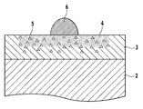
- FIG. 1 is an explanatory diagram of a recording medium on which an ink receiving layer is formed.
- FIG. 2 is an explanatory diagram of a state when ink is applied to the ink receiving layer of FIG.
- FIG. 3 is an explanatory diagram of a state when water droplets adhere to the ink receiving layer of FIG.
- FIG. 4 is a diagram for explaining the behavior of the organic solvent after water droplets adhere to the ink receiving layer in FIG. 2, and includes the parts (a) to (d).
- FIG. 5 includes portions (a) and (b), where the portion (a) is a plan view of the recorded matter in a state before water droplets adhere to the ink receiving layer of FIG. 2, and the portion (b) is FIG.
- FIG. 1 is an explanatory diagram of a recording medium on which an ink receiving layer is formed.
- FIG. 2 is an explanatory diagram of a state when ink is applied to the ink receiving layer of FIG.
- FIG. 3 is an explanatory diagram of a state when water
- FIG. 3 is a plan view of a recorded matter in a state after water droplets adhere to the ink receiving layer.
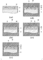
- FIG. 6 is an explanatory diagram of the processing steps in the embodiment of the present invention for reducing the organic solvent in the recorded matter, and includes portions (a) to (e).
- FIG. 7 is a partially cutaway perspective view of a printing element substrate applicable in the embodiment of the present invention.
- FIG. 8 is a sectional view taken along line VIII-VIII in FIG.
- FIG. 9 is a schematic configuration diagram of a full-line type ink jet recording apparatus to which the present invention can be applied.
- FIG. 1 is a schematic diagram of a recording medium used in the present invention, in which a so-called resin coat layer 2 is formed by coating mainly with a polyethylene resin on the front and back surfaces of a paper 1 serving as a base material.
- a so-called resin coat layer 2 is formed by coating mainly with a polyethylene resin on the front and back surfaces of a paper 1 serving as a base material.
- an ink receiving layer 3 for receiving ink for ink jet recording is formed on at least one surface of the paper 1.
- the ink receiving layer 3 is composed of a fine pigment such as silica or alumina having a particle diameter of about 100 nm or less.
- the ink receiving layer 3 in FIG. 1 has a single layer structure, but may have a multilayer structure.
- FIG. 2 is an explanatory view of a cross section when an image is recorded on such a recording medium using a dye ink.
- FIG. 3 is an explanatory diagram when water droplets 6 adhere to a recorded matter (recording medium on which an image is recorded) in the state shown in FIG. Part (a) of FIG. 4 is a diagram in which the illustration of the dye 4 is omitted from FIG. 3 in order to focus on the description of the organic solvent 5.
- the water droplet 6 adheres to the ink receiving layer 3
- the water droplet 6 starts to penetrate into the ink receiving layer 3.
- the organic solvent 5 in the ink receiving layer 3 is mixed with the water droplet 6 and starts to move with the diffusion of the water droplet 6 as shown in parts (b) and (c) of FIG.
- the water droplet 6 not only diffuses into the ink receiving layer 3 but also evaporates to the atmosphere, and finally the water droplet 6 is completely evaporated.
- the organic solvent 5 in the ink receiving layer 3 has a concentration gradient as shown in part (d) of FIG.
- Such a concentration gradient of the organic solvent 5 changes the light scattering component of the ink receiving layer 3 which is almost transparent, thereby causing a visually turbid state to appear.
- the top surface of the recorded material immediately after the image recording is in a state as shown in FIG. 5A, when the water droplet 6 adheres to this and then dries, the portion of FIG. As described above, there is a risk of uneven hue.
- the hue unevenness visually looks like a donut with the outline of the water droplet 6 left.
- Such water resistance deterioration of the recorded matter is caused by the organic solvent 5 which is a component other than the dye in the dye ink.
- the organic solvent 5 which is a component other than the dye in the dye ink.
- unevenness in hue caused by the organic solvent 5 is suppressed.
- Inkjet recording device Inkjet recording device
- a full line type ink jet recording apparatus as shown in FIG. 9 is used to record an image by the ink jet recording method.
- 40Bk, 40C, 40LC, 40M, 40LM, and 40Y are inkjet recording heads that can eject black, dark cyan, light cyan, dark magenta, light magenta, and yellow ink, respectively. These recording heads are collectively referred to as “recording head 40”.
- the recording head 40 ejects ink from the ejection port using ejection energy generating means such as an electrothermal conversion element (heater) or a piezo element.
- ejection energy generating means such as an electrothermal conversion element (heater) or a piezo element.
- the ink in the flow path communicating with the ejection port can be foamed by the heat generated when it is energized, and ink droplets can be ejected from the ejection port using the foam as a pressure source. .
- the recording medium 44 is an endless charging adsorption belt disposed opposite to the recording head 40, and 45 is a back platen arranged opposite to the recording head 40 via the charging adsorption belt 44.
- the recording medium is conveyed in the arrow Y direction through a recording position (image recording unit) facing the recording head 40 at a predetermined interval.
- Reference numeral 51 denotes a polar solvent ejection mechanism that reduces the organic solvent in the ink receiving layer of the recording medium by ejecting the polar solvent onto the recording medium on which the image is recorded.
- the polar solvent will be described later.
- Reference numeral 53 denotes a hot air heater for drying the polar solvent attached to the recording medium by the ejection mechanism 51.
- Reference numeral 55 denotes a discharge roller for discharging the recording medium on which image fixing has been completed to the outside of the apparatus, and 56 is a discharge tray (discharge section) for sequentially stocking the discharged recording medium.
- the recording operation starts from the roll paper 101 feeding operation. That is, the paper feed roller 103 rotates and the roll paper 101 is fed out from the holder 100. Thereafter, when the leading end of the roll paper 101 reaches the transport unit, the roll paper 101 is transported to the image recording unit by the transport force of the transport roller 111 and the guides of the transport guide pairs 112 and 113. Next, an image recording operation is started, ink droplets are ejected from the recording head 40, and an image is recorded on the roll paper 101 held on the platen 45. When the leading edge of the roll paper 101 on which the image is recorded reaches a position facing the photosensor 133, the photosensor 133 detects the leading edge of the roll paper.
- the roll paper 101 is conveyed until the portion that becomes the rear end of the recorded material reaches a position facing the cutter 132, and then the roll paper 101 is cut by the cutter 132. Then, a polar solvent is ejected from the ejection mechanism 51 to the cut roll paper 101, and the organic solvent in the ink receiving layer is washed away. Thereafter, the polar solvent adhering to the cut roll paper 101 is dried by the warm air heater 53, and then the roll paper 101 is discharged out of the apparatus (discharge paper tray 56) by the discharge roller 55. Thereby, a recorded matter in which the amount of the organic solvent in the ink receiving layer is reduced is obtained.
- the full-line type ink jet recording apparatus of this example applies color signals to the roll paper 101 by giving a recording signal to recording heads corresponding to black, dark cyan, light cyan, dark magenta, light magenta, and yellow ink. Continuous high-speed recording of images is possible.
- the present invention is applicable to a general serial scan type ink jet recording apparatus in addition to such a line type ink jet recording apparatus.
- the polar solvent ejecting mechanism 51 functions as an organic solvent reducing means, and reduces the organic solvent in the ink receiving layer of the recording medium by ejecting the polar solvent onto the recording medium (roll paper 101) in the form of a shower. To do.
- a mechanism that immerses the recording medium in a polar solvent solution may be used. Further, by adjusting the temperature of the polar solvent liquid, the organic solvent in the ink receiving layer and the polar solvent can be easily mixed, and the adjustment temperature is adjusted to a range of 25 ° C. to 80 ° C. Is preferred.
- Part (a) of FIG. 6 is a diagram schematically showing the organic solvent 5 and the voids 12 present in the ink receiving layer 3 of the recorded matter (recording medium after image recording).
- the polar solvent 10 enters the voids 12 in the ink receiving layer as shown in the part (c) of FIG. Infiltrate.
- the air in the gap 12 appears as bubbles 13 attached to the surface of the ink receiving layer 3.
- the organic solvent 5 in the ink receiving layer 3 replaces the polar solvent 10 and diffuses into the liquid of the polar solvent 10.
- the bubbles 13 adhere to the surface of the ink receiving layer 3 and work to inhibit the penetration of the polar solvent 10, the efficiency of replacing the polar solvent 10 and the organic solvent 5 is reduced (FIG. 6). Part (d)).
- the bubbles 13 attached to the surface of the ink receiving layer 3 are removed.
- an accelerating means for promoting such substitution for example, an ultrasonic vibration device that vibrates the liquid of the polar solvent 10 can be used. By such vibration, the organic solvent 5 and the polar solvent 10 in the ink receiving layer 3 can be quickly replaced as in the part (e) of FIG.
- a method of accelerating the replacement of the organic solvent 5 and the polar solvent 10 in the ink receiving layer 3 by a mechanism for oscillating the recorded matter can be adopted.
- a method of removing the bubbles 13 attached to the surface of the ink receiving layer 3 by ejecting the polar solvent 10 at a water pressure of 0.1 MPa or more can be employed.
- a promotion means can be used in combination. By using such a promoting means, the organic solvent 5 in the ink receiving layer 3 can be efficiently replaced with the polar solvent 10 in a short time.
- the oscillation frequency and high frequency output of vibration can be determined as appropriate.
- the oscillation frequency is in a general range of 20 kHz to 50 kHz, and the high frequency output is preferably 200 W or less mainly for the purpose of reducing bubbles 13. In these settings, it is necessary to prevent the recording medium from being destroyed by at least the interference of ultrasonic vibration.
- the number of swings is preferably in the range of 1 to 30 times / minute, and the swing stroke is preferably in the range of 1 to 100 mm.
- the present invention is not limited to this, and it is also possible to increase the swing stroke and repeat the immersion and removal from the polar solvent.
- the processing time by the promoting means can be appropriately determined from the recording conditions of the image recorded on the recording medium as the processing target. For example, set the maximum amount of ink applied per unit area on the recording medium, the total amount of ink applied to the recording medium, or the type and concentration of the organic solvent constituting the ink as a guide. Can do.
- the heater 53 as a drying means evaporates liquid droplets such as polar solvent adhering to the surface of the recording medium, thereby forcing the recording medium. Let dry. In such a drying means, it is possible to adjust the output of the heater 53 according to the recording speed of the recording apparatus. In some cases, the recording medium is naturally dried without using the heater 53. Also good. Various methods such as a drying method using an air knife can also be employed as the drying means.
- FIG. 7 is a perspective view in which a part of the recording element substrate 27 of this example is broken
- FIG. 8 is a cross-sectional view taken along line VIII-VIII in FIG.
- the recording element substrate 27 of this example has a discharge energy generating unit, a common ink chamber 31, an ink path 33, a discharge port 25, and the like on a silicon substrate having a thickness of 0.5 mm to 1 mm by using a film forming technique. It is formed.
- an electrothermal conversion element (heater) 29 is formed as an ink ejection energy generation unit.
- the recording element substrate 27 is formed on a silicon substrate having a thickness of 0.5 mm to 1 mm by using a film forming technique, an ejection energy generation unit, a common ink chamber 31, an ink path 33, an ejection port 25, and the like. Is formed.
- the recording element substrate 27 is formed with an elongated ink supply port 28 penetrating therethrough.
- an element array composed of a plurality of electrothermal conversion elements 29 is formed along a direction intersecting (in the present example, orthogonal) with the conveyance direction (Y direction) of the recording medium. .
- the plurality of electrothermal conversion elements 29 in each column are arranged at a predetermined interval (pitch), and the position of the electrothermal conversion element 29 in one column and the position of the electrothermal conversion element 29 in the other column are These are arranged with a half-pitch shift in the arrangement direction.
- the recording element substrate 27 is provided with electrode terminals 30 for electrical connection between the electrothermal conversion elements 29 and the recording apparatus main body, and aluminum (not shown). Electrical wiring and the like are formed by a film forming technique.
- An electrical wiring board (not shown) is connected to the electrode terminals 30 formed on the recording element board 27.
- the electrical wiring substrate is for applying an electrical signal for ejecting ink to the recording element substrate 27.
- the electrical wiring substrate corresponds to the recording element substrate 27 and is positioned at the end of the electrical wiring.
- a contact portion for receiving an electrical signal from the apparatus main body. The contact portion is positioned and fixed on the back side of a tank holder (not shown).
- a drive signal is supplied to the electrothermal conversion element 29 from a drive IC (not shown) via such an electrical wiring board, and at the same time, drive power is supplied to the electrothermal conversion element 29.
- An upper plate member 32 is formed on the recording element substrate 27, and the upper plate member 32 is connected to each of the plurality of electrothermal conversion elements 29 via a common ink chamber 31 communicating with the ink supply port 28.
- a plurality of discharge ports 25 facing each other are formed.
- Ink paths 33 are formed between the upper plate member 32 and the recording element substrate 27 so as to communicate between the individual ejection ports 25 and the common ink chamber 31.
- a partition wall 34 is provided between the adjacent ink paths 33. Is formed.
- the common ink chamber 31, the ink path 33, the partition wall 34, and the like are formed together with the upper plate member 32 by the photolithography technique, similarly to the ejection port 25.
- the ink supplied from the ink supply port 28 into each ink path 33 is foamed as the electrothermal conversion element 29 generates heat when a drive signal is given to the electrothermal conversion element 29 facing the ink path 33.
- the liquid is discharged from the discharge port 25 by the foaming pressure.
- a piezo element or the like can also be used as the discharge energy generating unit.
- polar solvent a solvent capable of reducing the non-volatile organic solvent in the ink receiving layer of the recording medium. Specific examples include water and alcohols having 5 or less carbon atoms, preferably lower alcohols such as methyl alcohol, ethyl alcohol, and propyl alcohol.
- the polar solvent used in the present invention is not limited to those listed here, but particularly preferred is water, and it is desirable to use deionized water.
- the dye ink preferably contains a dye and an organic solvent described later.
- dyes Conventionally known dyes can be used as the coloring material of the ink.
- acid dyes, direct dyes, disperse dyes, and the like can be used.
- anionic dyes existing ones or newly synthesized ones can be used as long as they have an appropriate color tone and density. Moreover, it is also possible to use a mixture of two or more of these. Specific examples of the anionic dye are listed below.
- Alkyl alcohols having 1 to 4 carbon atoms such as methyl alcohol, ethyl alcohol, n-propyl alcohol, isopropyl alcohol, n-butyl alcohol, sec-butyl alcohol, tert-butyl alcohol; Amides such as dimethylformamide and dimethylacetamide; Ketones or ketoalcohols such as acetone and diacetone alcohol; Ethers such as tetrahydrofuran and dioxane; Polyalkylene glycols such as polyethylene glycol and polypropylene glycol; Alkylene glycols in which the alkylene group contains 2 to 6 carbon atoms, such as ethylene glycol, propylene glycol, butylene glycol, triethylene glycol, 1,2,6-hexanetriol, thiodiglycol, hexylene glycol, diethylene glycol; Lower alkyl ether acetates such as polyethylene glycol monomethyl
- organic solvents it is preferable to use an organic solvent having a boiling point of 180 ° C. or higher, and it is possible to prevent sticking in the vicinity of the discharge port of the ink jet recording head and to perform a stable recording operation.
- organic solvents may be used alone or as a mixture, and the type and amount thereof can be appropriately selected.
- an ink jet recording head having the recording element substrate 27 as shown in FIGS. 7 and 8 was manufactured.
- the recording head is used for a full-line type recording apparatus, and has an ink ejection amount of about 3 ng, an ejection port array resolution in the ejection port array direction of 1200 dpi, and an ejection port array length of 4.25 inches. .
- Six such recording heads were prepared, and a line type printer as shown in FIG. 9 was prepared.
- the ink supply system was configured to discharge the dye inks BCI-7eBK, BCI-7eC, BCI-7ePC, BCI-7eM, BCI-7ePM, and BCI-7eY (made by Canon) from each recording head. These inks correspond to the ink colors of black, dark cyan, light cyan, dark magenta, light magenta, and yellow, and are ejected from the recording heads 40Bk, 40C, 40LC, 40M, 40LM, and 40Y. Further, as the roll paper (recording medium) 101, a 4-inch wide roll paper (100 m) of Super Photo Paper SP-101 was mounted on the line printer of FIG. The ink receiving layer 3 as described above is formed on the roll paper.
- a color image can be continuously recorded on the roll paper 101 by ejecting ink from each recording head.
- the organic solvent 5 and the voids 12 exist as shown in the part (a) of FIG.
- the roll paper 101 on which the image is recorded is cut by the cutter 132, and then the organic solvent reduction process by the polar solvent injection mechanism 51 and the drying process by the hot air heater 53 are performed.
- a polar solvent is ejected by the ejection mechanism 51, the liquid pressure is 0.055 MPa, the liquid flow rate is 1 liter / min, and the processing time is 60. Seconds.
- the drying apparatus provided with the warm air heater 53 set the warm air temperature to 70 ° C., the wind speed to 5 m / s, and the processing time to 10 seconds.
- the line type printer shown in FIG. 9 was operated, and 6 4 ⁇ 6 inch size printed matter (samples) in which a solid image for each ink color was recorded were created.
- the apparatus used in the present embodiment replaces the holder 100 in the ink jet recording apparatus of FIG. 9 with a cut sheet feeding mechanism, replaces the ejection mechanism 51 with an ultrasonic cleaner, and further automatically supplies a recording medium to the ultrasonic cleaner.
- the cutter 132 is not essential but may be provided.
- the photo sensor 133 is used to detect the trailing edge of the recording medium.
- a solid image for each ink color is recorded on Canon photo paper glossy gold GL-101 (L size) as in the above-described embodiment.
- the recording medium on which the solid image is recorded is supplied into the liquid tank (water tank) of the ultrasonic cleaning machine.
- the temperature of the pure water (polar solvent) in the water tank is controlled at 55 ° C., and ultrasonic vibration is given by the ultrasonic vibrator.
- the recording medium is immersed in water in such a water tank for 5 seconds to reduce the organic solvent in the ink receiving layer of the recording medium.
- the recording medium discharged from the water tank is conveyed to a drying unit having a warm air heater, and the recording medium is dried in the drying unit. Thereby, a recorded matter on which a solid image is recorded is obtained.
- six recorded materials on which solid images of the six inks were recorded were obtained.
- the immersion time is 60 seconds. It was necessary. From this, it was found that the ultrasonic vibration has an effect of shortening the immersion time of the recorded matter necessary for obtaining a sufficient reduction effect of the organic solvent.
- an organic solvent reducing means including a water tank and a rocking means for rocking the water tank is used. The same as in the second embodiment.
- the recording medium on which the image is recorded is immersed in pure water (polar solvent) in the water tank, and the water tank is maintained for 10 seconds with a rocking cycle of about 0.5 seconds and a rocking stroke of about 3 cm during the immersion. Was rocked. Thereafter, the recording medium discharged from the water tank was conveyed to a drying unit having a warm air heater, and the recording medium was dried in the drying unit. Thereby, a recorded matter on which a solid image is recorded is obtained.
- pure water polar solvent
- the present invention can treat various recorded materials on which images are recorded by applying an ink containing at least a coloring material and an organic solvent to the porous ink-receiving layer.
- the present invention can be widely applied regardless of the type of recorded image.
- it is only necessary to reduce the organic solvent in the ink receiving layer by bringing a polar solvent into contact with the ink receiving layer of the recorded matter and various methods can be adopted as the reduction processing method. .
- a method of immersing a recorded material in a liquid containing a polar solvent or a method of spraying a liquid containing a polar solvent onto the recorded material can be employed.
Landscapes
- Ink Jet (AREA)
- Ink Jet Recording Methods And Recording Media Thereof (AREA)
Abstract
記録物に水滴が付着したときに、その記録物に残留する有機溶媒の局在化に起因する画像劣化を抑制して、耐水性を向上させることができる記録物の処理装置、処理方法、記録装置、および記録方法を提供する。多孔質からなるインク受容層(3)に、少なくとも色材と有機溶媒(5)を含むインクが付与されることによって画像が記録された記録物に対して、インク受容層(3)内の有機溶媒(5)を極性溶媒(10)によって置換するための処理を施す。
Description
本発明は、耐水性の優れた記録物を作成ための記録装置および記録物の製造方法に関するものである。
インクジェット記録法は、近年における画質の飛躍的な向上により、写真画像の記録手段として定着しつつある。記録画像の画質は、銀塩写真と同等、あるいはそれ以上のものが得られるようになったが、その保存性については必ずしも十分とはいいきれない。記録画像の保存性においては、耐光性、耐ガス性、耐水性、および耐擦過性等が課題となる。特に、染料インクによって記録された記録物の場合には、その記録物上に滴下した水滴(例えば、雨、汗、唾液等)によって画像が滲むおそれがある。
このような水滴による画像の滲みを低減する策としては、水滴が付かないように記録物を透明フィルムによって保護するラミネート法が効果的である。ラミネート法以外の方法としては、染料の染着性を改良し、画像の耐水性を向上させた記録媒体として、カチオン性架橋樹脂微粒子とバインダー樹脂を含有する記録媒体が提案されている(特許文献1)。また、記録媒体として、無機微粒子と、水溶性アルミニウム化合物と、ジルコニウム化合物と、カチオン変性された自己乳化性高分子と、ポリビニルアルコールと、架橋剤と、を含むインク受容層を有するインクジェット記録媒体が提案されている(特許文献2)。またインクとしては、染料構造中に少なくとも1つの特定の構造単位を導入することにより、耐水性を改善した染料インクが開示されている(特許文献3)。
しかしながら、以上の技術によれば、ラミネートの場合には新たに透明フィルムが必要となり、大幅なコストアップを招くおそれがある。また、カチオン性物質を含有した記録媒体や、特定の染料構造を有した染料インクを用いた場合、確かに染料に起因する耐水性は向上する。しかしながら、これらの場合には、新たな課題として記録画像の色相ムラが認識された。この色相ムラの発生原因としては、以下のようなメカニズムが考えられる。
インクジェット記録ヘッドの吐出口から吐出されるインクジェット記録用の水性インクにおいては、記録ヘッドの信頼性を保つために、不揮発性の有機溶媒を含有している場合がほとんどである。水性インクが不揮発性の有機溶媒を含有している理由の1つとしては、記録ヘッドの吐出口近傍での固着を防止して、記録動作を安定化させる目的が挙げられる。この不揮発性の有機溶媒は、染料インクと共に記録媒体に付与されて、その記録媒体中に留まることになる。多孔質のインク受容層を有する記録媒体を用いた場合には、そのインク受容層中に不揮発性の有機溶媒が留まることになる。画像が記録された記録媒体上に、雨、汗、唾液等のような液滴が滴下された場合、それらの液滴は、インク受容層内に浸透して不揮発性の有機溶媒と混合する。そのような液滴は、インク受容層内に拡散しながら自然蒸発し、最終的にインク受容層は乾燥する。その際、インク受容層内に存在していた不揮発性の有機溶媒は、初期状態とは異なった状態で存在することになり、それは液滴の拡散方向に局在化すると考えられる。
本発明者の検討の結果、このような不揮発性の有機溶媒の分布によって、多孔質のインク受容層の光の散乱度合いが変化し、記録物の色相が変化して画像劣化を招くことが明らかとなった。上記の特許文献1、特許文献2、特許文献3に記載の技術では、このような不揮発性の有機溶媒の存在の局在化による画像劣化は改善できない。
本発明の目的は、記録物に水滴が付着したときに、その記録物に残留する有機溶媒の局在化に起因する画像劣化を抑制して、耐水性を向上させることができる記録装置および記録物の製造方法を提供することにある。
本発明の記録装置は、多孔質のインク受容層を有する記録媒体に、少なくとも色材と有機溶媒を含むインクを付与して画像を記録する記録手段と、前記記録手段によって画像が記録された記録媒体の前記インク受容層に極性溶媒を接触させることで前記インク受容層内の有機溶媒を低減させる処理を行う処理手段と、を備えることを特徴とする。
本発明の記録物の製造方法は、記録物製造装置を用いて記録物を製造する方法であって、多孔質のインク受容層を有する記録媒体に、少なくとも染料と有機溶媒を含むインクを記録ヘッドから付与することにより、前記記録媒体に画像を記録し、前記画像が記録された記録媒体の前記インク受容層に極性溶媒を接触させることで前記インク受容層内の有機溶媒を低減し、前記有機溶媒が低減された記録媒体を乾燥し、乾燥された記録媒体を前記記録物として記録物製造装置から排出することを特徴とする。
本発明によれば、色材と有機溶媒を含むインクが付与されたインク受容層に極性溶媒を接触させることでインク受容層に残留している有機溶媒を低減することにより、記録物の耐水性を向上させることができる。すなわち、記録物に残留している有機溶媒を低減することにより、水滴が付着したときの有機溶媒の局在化に起因する画像劣化を抑制して、耐水性を向上させることができる。
以下、本発明の実施形態を図面に基づいて説明する。
(第1の実施形態)
以下、本発明の実施形態を説明する前に、本発明による解決課題を図1から図5を用いて説明する。
以下、本発明の実施形態を説明する前に、本発明による解決課題を図1から図5を用いて説明する。
図1は、本発明で用いる記録媒体の模式図であり、基材となる紙1の表裏面に、主にポリエチレン樹脂によるコーティングがなされて、いわゆるレジンコート層2が形成されている。紙1の少なくとも一方の面には、インクジェット記録用のインクを受容するためのインク受容層3が形成されている。一般的に、このインク受容層3は、粒径100nm程度以下のシリカ、アルミナ等の微細顔料によって構成されている。図1におけるインク受容層3は、単層構造となっているが多層構造であってもよい。
図2は、このような記録媒体に、染料インクを用いて画像を記録した場合の断面の説明図である。前述した特許文献1、2、3に記載されている技術により、染料インク中の染料4がインク受容層3に強固に定着する。また同時に、染料インク中に含有している不揮発性の有機溶媒5は、インク受容層3中に残留する。
図3は、図2のような状態にある記録物(画像が記録された記録媒体)に水滴6が付着したときの説明図である。図4の部分(a)は、有機溶媒5の説明に焦点を当てるために、図3から染料4の図示を削除した図である。水滴6がインク受容層3に付着すると、水滴6はインク受容層3中に浸透を開始する。このとき、インク受容層3中にある有機溶媒5は、水滴6と混合して図4の部分(b),(c)のように水滴6の拡散とともに移動し始める。そして水滴6は、インク受容層3中への拡散だけではなく、大気への蒸発も進行して、最終的に水滴6は完全蒸発する。このとき、インク受容層3中にある有機溶媒5には、図4の部分(d)のような濃度勾配が生じる。
このような有機溶媒5の濃度勾配は、ほぼ透明であったインク受容層3の光の散乱成分を変化させて、視覚的に濁った状態を発現させる。画像の記録直後の記録物の上面が図5の部分(a)のような状態であった場合、これに水滴6が付着してから、それが乾燥したときには、図5の部分(b)のように色相ムラが発生するおそれがある。その色相ムラは、視覚的に、水滴6の輪郭を残したようなドーナツ状に見える。
このような記録物の耐水性劣化は、染料インク中の染料以外の含有成分である有機溶媒5によって発生する。本発明は、この有機溶媒5によって発生する色相ムラを抑制するものである。
以下、本発明の実施形態について説明する。
(インクジェット記録装置)
本例では、画像をインクジェット記録方式によって記録するために、図9のようなフルラインタイプのインクジェット記録装置(プリンタ)を用いる。
本例では、画像をインクジェット記録方式によって記録するために、図9のようなフルラインタイプのインクジェット記録装置(プリンタ)を用いる。
図9において、40Bk,40C,40LC,40M,40LM,40Yは、それぞれ、ブラック,濃シアン,淡シアン,濃マゼンタ,淡マゼンタ,イエローのインクを吐出可能なインクジェット記録ヘッドである。これらの記録ヘッドをまとめて、「記録ヘッド40」ともいう。記録ヘッド40は、電気熱変換素子(ヒータ)やピエゾ素子などの吐出エネルギー発生手段を用いて、吐出口からインクを吐出する。電気熱変換素子を用いた場合には、それに通電したときの発熱によって、吐出口に連通する流路内のインクを発泡させ、その発泡を圧力源として吐出口からインク滴を吐出することができる。
44は、記録ヘッド40と対向配置されるエンドレスの帯電吸着ベルトであり、45は、帯電吸着ベルト44を介して記録ヘッド40に対向配置されるバックプラテンである。これらによって、記録媒体は、所定間隔をおいて記録ヘッド40と対向する記録位置(画像記録部)を通って矢印Y方向に搬送される。
51は極性溶媒の噴射機構であり、画像が記録された記録媒体に極性溶媒を噴射することによって、その記録媒体のインク受容層中の有機溶媒を低減するものである。極性溶媒については後述する。53は、噴射機構51によって記録媒体に付着された極性溶媒を乾燥させるための温風ヒータである。55は、画像の定着が終了した記録媒体を装置外に排出するための排出ローラー、56は、排出された記録媒体を順次ストックするための排紙トレイ(排出部)である。
次に、このような構成の記録装置の一連の動作について説明する。以下で説明する一連の動作に係わる各部(給紙ローラ、搬送ローラ、記録ヘッド、低減手段等)の駆動は、CPUを有する制御部(不図示)によって制御される。ここでは、記録媒体としてロール紙を給紙して記録する手順について説明する。ロール紙101は、スプール102を介してホルダー100内に回転自在に支持されており、そのロール紙101の先端部が給紙ローラー103に挟まれた状態でセットされている。
記録動作は、まず、ロール紙101の給紙動作から開始する。すなわち、給紙ローラー103が回転してロール紙101がホルダー100から繰り出される。その後、ロール紙101は、その先端部が搬送部に達すると、搬送ローラー111の搬送力、および搬送ガイド対112、113の案内によって、画像記録部まで搬送される。次に、画像の記録動作を開始し、記録ヘッド40からインク滴を吐出して、プラテン45上に保持されたロール紙101に画像を記録する。画像が記録されたロール紙101の先端がフォトセンサ133に対向する位置まで到達したら、フォトセンサ133はロール紙の先端を検知する。この検知結果に基づいて、記録物の後端となる部分がカッター132に対向する位置に達するまでロール紙101を搬送し、その後、このカッター132によってロール紙101をカットする。そして、カットされたロール紙101に対して、噴射機構51から極性溶媒を噴射して、インク受容層中の有機溶媒を洗い流す。その後、カットされたロール紙101に付着した極性溶媒を温風ヒータ53で乾燥させてから、そのロール紙101を排紙ローラー55によって機外(排紙紙トレイ56)に排出する。これにより、インク受容層中の有機溶媒量が低減された記録物が得られる。
本例のフルラインタイプのインクジェット記録装置は、ブラック,濃シアン,淡シアン,濃マゼンタ,淡マゼンタ,イエローのインクに対応する記録ヘッドに記録信号を与えることにより、ロール紙101に対して、カラー画像の連続的な高速記録が可能である。本発明は、このようなラインタイプのインクジェット記録装置の他、一般的なシリアルスキャンタイプのインクジェット記録装置に対しても適用可能である。
(有機溶媒の低減手段)
極性溶媒の噴射機構51は、有機溶媒の低減手段として機能し、極性溶媒をシャワー状にして記録媒体(ロール紙101)に噴射することによって、その記録媒体のインク受容層中の有機溶媒を低減する。このような有機溶媒の低減手段としては、極性溶媒の溶液中に記録媒体を浸漬させるような機構のものを用いてもよい。また、極性溶媒の液体を温度調整することにより、インク受容層中の有機溶媒と、極性溶媒と、を混合しやすくすることができ、その調整温度は25℃~80℃の範囲に調整することが好ましい。
極性溶媒の噴射機構51は、有機溶媒の低減手段として機能し、極性溶媒をシャワー状にして記録媒体(ロール紙101)に噴射することによって、その記録媒体のインク受容層中の有機溶媒を低減する。このような有機溶媒の低減手段としては、極性溶媒の溶液中に記録媒体を浸漬させるような機構のものを用いてもよい。また、極性溶媒の液体を温度調整することにより、インク受容層中の有機溶媒と、極性溶媒と、を混合しやすくすることができ、その調整温度は25℃~80℃の範囲に調整することが好ましい。
(促進手段)
画像記録後であっても、記録媒体のインク受容層を構成している多孔質体には多くの空隙が存在している。図6の部分(a)は、記録物(画像記録後の記録媒体)のインク受容層3内に存在する有機溶媒5と空隙12を模式的に現した図である。図6の部分(b)のように、このような記録物を極性溶媒10の液体中に浸漬すると、極性溶媒10は、図6の部分(c)のようにインク受容層中の空隙12に浸入する。その空隙12にあった空気は、インク受容層3の表面に付着する気泡13となって現れる。また同時に、インク受容層3内の有機溶媒5が極性溶媒10と置換して、極性溶媒10の液体中に拡散する。しかしながら、気泡13がインク受容層3の表面に付着して、極性溶媒10の浸入を阻害するように働くため、極性溶媒10と有機溶媒5を置換する効率が落とされることになる(図6の部分(d))。
画像記録後であっても、記録媒体のインク受容層を構成している多孔質体には多くの空隙が存在している。図6の部分(a)は、記録物(画像記録後の記録媒体)のインク受容層3内に存在する有機溶媒5と空隙12を模式的に現した図である。図6の部分(b)のように、このような記録物を極性溶媒10の液体中に浸漬すると、極性溶媒10は、図6の部分(c)のようにインク受容層中の空隙12に浸入する。その空隙12にあった空気は、インク受容層3の表面に付着する気泡13となって現れる。また同時に、インク受容層3内の有機溶媒5が極性溶媒10と置換して、極性溶媒10の液体中に拡散する。しかしながら、気泡13がインク受容層3の表面に付着して、極性溶媒10の浸入を阻害するように働くため、極性溶媒10と有機溶媒5を置換する効率が落とされることになる(図6の部分(d))。
そこで、図6の部分(e)に示すように、極性溶媒10と有機溶媒5の置換を促進するために、インク受容層3の表面に付着した気泡13を取り除く。このような置換を促進するための促進手段としては、例えば、極性溶媒10の液体を振動させる超音波振動装置等を用いることができる。このような振動によって、図6の部分(e)のようにインク受容層3内にある有機溶媒5と極性溶媒10とを素早く置換させることができる。また、他の促進手段としては、記録物を揺動させる機構によって、インク受容層3内の有機溶媒5と極性溶媒10との置換を促進する方法を採用することもできる。あるいは、極性溶媒10を0.1MPa以上の水圧にして噴射させることによって、インク受容層3の表面に付着した気泡13を取り除く方法なども採用することができる。また、このような促進手段を併用することもできる。このような促進手段を用いることにより、インク受容層3中にある有機溶媒5を極性溶媒10と効率良く短時間で置換することができる。
また、このような促進手段として超音波振動装置を用いる場合には、振動の発振周波数および高周波出力は適宜決めることができる。発振周波数は、一般的な20kHz~50kHzの範囲として、高周波出力は、主に気泡13の低減を目的とするために200W以下であることが好ましい。これらの設定に際しては、少なくとも超音波振動の干渉によって記録媒体が破壊されないようにすることが必要となる。
また、促進手段として揺動機構を用いる場合、揺動回数は1~30回/分、揺動ストロークは1~100mmの範囲であることが好ましい。しかし、これに限定されることはなく、揺動ストロークを長くして、極性溶媒への浸漬と取り出しを繰り返すことも可能である。
また、促進手段による処理時間は、処理対象としての記録媒体に記録された画像の記録条件等から適宜決定することができる。例えば、記録媒体上の単位面積当たりのインクの付与量の最大値、記録媒体に付与されるインクの総付与量、あるいはインクを構成する有機溶媒の種類や濃度等を目安にして、設定することができる。
(乾燥手段)
促進手段によって処理された記録媒体が濡れた状態で排紙されないように、乾燥手段としてのヒータ53によって、記録媒体の表面に付着した極性溶媒等の液滴を蒸発させて、記録媒体を強制的に乾燥させる。このような乾燥手段においては、記録装置の記録速度に応じて、ヒータ53の出力を調整することも可能であり、また場合によっては、ヒータ53を使わずに記録媒体を自然乾燥させるようにしてもよい。また、乾燥手段として、エアーナイフによる乾燥方法等の種々の方法を採用することもできる。
促進手段によって処理された記録媒体が濡れた状態で排紙されないように、乾燥手段としてのヒータ53によって、記録媒体の表面に付着した極性溶媒等の液滴を蒸発させて、記録媒体を強制的に乾燥させる。このような乾燥手段においては、記録装置の記録速度に応じて、ヒータ53の出力を調整することも可能であり、また場合によっては、ヒータ53を使わずに記録媒体を自然乾燥させるようにしてもよい。また、乾燥手段として、エアーナイフによる乾燥方法等の種々の方法を採用することもできる。
(記録ヘッド)
次に、本発明を適用可能な記録ヘッドにおける記録素子基板の構成例図7および図8に基づいて説明する。図7は、本例の記録素子基板27の一部を破断した斜視図であり、図8は、図7のVIII-VIII線に沿う断面図である。
次に、本発明を適用可能な記録ヘッドにおける記録素子基板の構成例図7および図8に基づいて説明する。図7は、本例の記録素子基板27の一部を破断した斜視図であり、図8は、図7のVIII-VIII線に沿う断面図である。
本例の記録素子基板27は、厚さが0.5mm~1mmのシリコン基板の上に、成膜技術を用いて、吐出エネルギー発生部、共通インク室31、インク路33、吐出口25などが形成されたものである。本例の場合は、インクの吐出エネルギー発生部として電気熱変換素子(ヒータ)29が形成されている。本実施形態における記録素子基板27は、厚さが0.5mm~1mmのシリコン基板の上に、成膜技術を用いて、吐出エネルギー発生部、共通インク室31、インク路33、吐出口25などを形成したものである。記録素子基板27には、これを貫通する長孔状のインク供給口28が形成されている。
インク供給口28の両側には、記録媒体の搬送方向(Y方向)と交差(本例の場合は、直交)する方向に沿って、複数の電熱変換素子29からなる素子列が形成されている。それぞれの列における複数の電気熱変換素子29は、所定の間隔(ピッチ)で配列されており、一方の列の電気熱変換素子29の位置と、他方の列の電気熱変換素子29の位置は、それらの配列方向において半ピッチずれて配置されている。記録素子基板27には、これらの電気熱変換素子29の他、電気熱変換素子29と記録装置本体側との電気的接続を行うための電極端子30、およびアルミニウムなどで形成される不図示の電気配線などが成膜技術によって形成されている。
記録素子基板27に形成された電極端子30に対しては、不図示の電気配線基板が接続される。その電気配線基板は、記録素子基板27に対して、インクを吐出するための電気信号を印加するためのものであり、記録素子基板27に対応する電気配線と、この電気配線の端部に位置して、装置本体からの電気信号を受け取るためのコンタクト部と、を有する。そのコンタクト部は、不図示のタンクホルダの背面側に位置決め固定される。このような電気配線基板を介して、図示しない駆動ICから電気熱変換素子29に対して駆動信号が与えられ、同時に、駆動電力が電気熱変換素子29に供給される。
記録素子基板27上には上板部材32が形成されており、その上板部材32には、インク供給口28に連通する共通インク室31を介して、複数の電気熱変換素子29のそれぞれと正対する複数の吐出口25が形成されている。上板部材32と記録素子基板27との間には、個々の吐出口25と共通インク室31との間を連通するインク路33が形成され、隣接するインク路33の間には仕切り壁34が形成されている。これらの共通インク室31、インク路33、および仕切り壁34などは、吐出口25と同様に、フォトリソグラフィ技術により上板部材32と共に形成される。
インク供給口28から各インク路33内に供給されるインクは、そのインク路33に臨む電気熱変換素子29に駆動信号が与えられることにより、その電気熱変換素子29の発熱に伴って発泡し、その発泡の圧力によって吐出口25から吐出される。吐出エネルギー発生部としては、電気熱変換素子29の他、ピエゾ素子などを用いることもできる。
(極性溶媒)
極性溶媒としては、記録媒体のインク受容層中にある不揮発性の有機溶媒を低減できるものが用いられる。具体例としては、水、炭素数5以下のアルコール、好ましくはメチルアルコール、エチルアルコール、プロピルアルコール等の低級アルコールを用いることができる。本発明において用いる極性溶媒は、ここに挙げたものに限定されないが、特に好ましいものは水であり、脱イオン水を使用することが望ましい。
極性溶媒としては、記録媒体のインク受容層中にある不揮発性の有機溶媒を低減できるものが用いられる。具体例としては、水、炭素数5以下のアルコール、好ましくはメチルアルコール、エチルアルコール、プロピルアルコール等の低級アルコールを用いることができる。本発明において用いる極性溶媒は、ここに挙げたものに限定されないが、特に好ましいものは水であり、脱イオン水を使用することが望ましい。
(染料インク)
本実施形態では、色材として染料を含有した染料インクを用いることが好適である。染料インクには、水の他に、後述する染料および有機溶剤を含有させることが好ましい。
本実施形態では、色材として染料を含有した染料インクを用いることが好適である。染料インクには、水の他に、後述する染料および有機溶剤を含有させることが好ましい。
(染料)
インクの色材として用いる染料は、従来から公知のものを用いることができ、例えば、酸性染料、直接染料、分散染料等を用いることができる。例えば、アニオン性染料として、既存のものでも、新規に合成したものでも、適度な色調と濃度とを有するものであれば大抵のものを用いることができる。また、これらの内のいずれかを2つ以上混合して用いることも可能である。アニオン性染料の具体例を以下に挙げる。
インクの色材として用いる染料は、従来から公知のものを用いることができ、例えば、酸性染料、直接染料、分散染料等を用いることができる。例えば、アニオン性染料として、既存のものでも、新規に合成したものでも、適度な色調と濃度とを有するものであれば大抵のものを用いることができる。また、これらの内のいずれかを2つ以上混合して用いることも可能である。アニオン性染料の具体例を以下に挙げる。
(イエロー用の色材)
C.I.ダイレクトイエロー8、11、12、27、28、33、39、44、50、58、85、86、87、88、89、98、100、110、132
C.I.アシッドイエロー1、3、7、11、17、23、25、29、36、38、40、42、44、76、98、99
C.I.リィアクティブイエロー2、3、17、25、37、42
C.I.フードイエロー3
C.I.ダイレクトイエロー8、11、12、27、28、33、39、44、50、58、85、86、87、88、89、98、100、110、132
C.I.アシッドイエロー1、3、7、11、17、23、25、29、36、38、40、42、44、76、98、99
C.I.リィアクティブイエロー2、3、17、25、37、42
C.I.フードイエロー3
(レッド用の色材)
C.I.ダイレクトレッド2、4、9、11、20、23、24、31、39、46、62、75、79、80、83、89、95、197、201、218、220、224、225、226、227、228、229、230
C.I.アシッドレッド6、8、9、13、14、18、26、27、32、35、42、51、52、80、83、87、89、92、106、114、115、133、134、145、158、198、249、265、289
C.I.リィアクティブレッド7、12、13、15、17、20、23、24、31、42、45、46、59
C.I.フードレッド87、92、94
C.I.ダイレクトレッド2、4、9、11、20、23、24、31、39、46、62、75、79、80、83、89、95、197、201、218、220、224、225、226、227、228、229、230
C.I.アシッドレッド6、8、9、13、14、18、26、27、32、35、42、51、52、80、83、87、89、92、106、114、115、133、134、145、158、198、249、265、289
C.I.リィアクティブレッド7、12、13、15、17、20、23、24、31、42、45、46、59
C.I.フードレッド87、92、94
(ブルー用の色材)
C.I.ダイレクトブルー1、15、22、25、41、76、77、80、86、90、98、106、108、120、158、163、168、199、226
C.I.アシッドブルー1、7、9、15、22、23、25、29、40、43、59、62、74、78、80、90、100、102、104、117、127、138、158、161
C.I.リィアクティブブルー4、5、7、13、14、15、18、19、21、26、27、29、32、38、40、44、100
C.I.ダイレクトブルー1、15、22、25、41、76、77、80、86、90、98、106、108、120、158、163、168、199、226
C.I.アシッドブルー1、7、9、15、22、23、25、29、40、43、59、62、74、78、80、90、100、102、104、117、127、138、158、161
C.I.リィアクティブブルー4、5、7、13、14、15、18、19、21、26、27、29、32、38、40、44、100
(ブラック用色材)
C.I.ダイレクトブラック17、19、22、31、32、51、62、71、74、112、113、154、168、195
C.I.アシッドブラック2、48、51、52、110、115、156
C.I.フードブラック1、2
C.I.ダイレクトブラック17、19、22、31、32、51、62、71、74、112、113、154、168、195
C.I.アシッドブラック2、48、51、52、110、115、156
C.I.フードブラック1、2
(有機溶媒)
インクに含有する有機溶媒としては、具体的には、
メチルアルコール、エチルアルコール、n-プロピルアルコール、イソプロピルアルコール、n-ブチルアルコール、sec-ブチルアルコール、tert-ブチルアルコール等の炭素数1~4のアルキルアルコール類;
ジメチルホルムアミド、ジメチルアセトアミド等のアミド類;
アセトン、ジアセトンアルコール等のケトン又はケトアルコール類;
テトラヒドロフラン、ジオキサン等のエーテル類;
ポリエチレングリコール、ポリプロピレングリコール等のポリアルキレングリコール類;
エチレングリコール、プロピレングリコール、ブチレングリコール、トリエチレングリコール、1,2,6-ヘキサントリオール、チオジグリコール、ヘキシレングリコール、ジエチレングリコール等のアルキレン基が2~6個の炭素原子を含むアルキレングリコール類;
ポリエチレングリコールモノメチルエーテルアセテート等の低級アルキルエーテルアセテート;
グリセリン;
エチレングリコールモノメチル(又はエチル)エーテル、ジエチレングリコールメチル(又はエチル)エーテル、トリエチレングリコールモノメチル(又はエチル)エーテル等の多価アルコールの低級アルキルエーテル類;
トリメチロールプロパン、トリメチロールエタン等の多価アルコール;
N-メチル-2-ピロリドン、2-ピロリドン、1,3-ジメチル-2-イミダゾリジノン等が挙げられる。
インクに含有する有機溶媒としては、具体的には、
メチルアルコール、エチルアルコール、n-プロピルアルコール、イソプロピルアルコール、n-ブチルアルコール、sec-ブチルアルコール、tert-ブチルアルコール等の炭素数1~4のアルキルアルコール類;
ジメチルホルムアミド、ジメチルアセトアミド等のアミド類;
アセトン、ジアセトンアルコール等のケトン又はケトアルコール類;
テトラヒドロフラン、ジオキサン等のエーテル類;
ポリエチレングリコール、ポリプロピレングリコール等のポリアルキレングリコール類;
エチレングリコール、プロピレングリコール、ブチレングリコール、トリエチレングリコール、1,2,6-ヘキサントリオール、チオジグリコール、ヘキシレングリコール、ジエチレングリコール等のアルキレン基が2~6個の炭素原子を含むアルキレングリコール類;
ポリエチレングリコールモノメチルエーテルアセテート等の低級アルキルエーテルアセテート;
グリセリン;
エチレングリコールモノメチル(又はエチル)エーテル、ジエチレングリコールメチル(又はエチル)エーテル、トリエチレングリコールモノメチル(又はエチル)エーテル等の多価アルコールの低級アルキルエーテル類;
トリメチロールプロパン、トリメチロールエタン等の多価アルコール;
N-メチル-2-ピロリドン、2-ピロリドン、1,3-ジメチル-2-イミダゾリジノン等が挙げられる。
これらの有機溶媒において、沸点が180℃以上の有機溶媒の利用が好ましく、インクジェット記録ヘッドの吐出口近傍での固着を防止して、安定的な記録動作が可能となる。これらの有機溶媒は、単独でも或いは混合物として用いてもよく、それらの種類および量は適宜選択できる。
(記録動作および記録物の処理内容のまとめ)
本実施形態においては、図7および図8のような記録素子基板27を有するインクジェット記録ヘッドを製造した。その記録ヘッドは、フルラインタイプの記録装置に用いられるものであり、インクの吐出量が約3ng、吐出口配列方向の吐出口の配列解像度が1200dpi、吐出口列長が4.25インチである。このような記録ヘッドを6つ作製し、それらを装着可能な図9のようなラインタイプのプリンタを作製した。それぞれの記録ヘッドから、染料インクのBCI-7eBK、BCI-7eC、BCI-7ePC、BCI-7eM、BCI-7ePM、BCI-7eY(キヤノン製)を吐出するように、インクの供給系を構成した。それらのインクは、ブラック、濃シアン、淡シアン、濃マゼンタ、淡マゼンタ、イエローのインク色に対応し、記録ヘッド40Bk,40C,40LC,40M,40LM,40Yから吐出される。また、ロール紙(記録媒体)101として、スーパーフォトペーパーSP-101の4インチ幅ロール紙(100m)を図9のラインプリンタに搭載した。そのロール紙には、前述したようなインク受容層3が形成されている。
本実施形態においては、図7および図8のような記録素子基板27を有するインクジェット記録ヘッドを製造した。その記録ヘッドは、フルラインタイプの記録装置に用いられるものであり、インクの吐出量が約3ng、吐出口配列方向の吐出口の配列解像度が1200dpi、吐出口列長が4.25インチである。このような記録ヘッドを6つ作製し、それらを装着可能な図9のようなラインタイプのプリンタを作製した。それぞれの記録ヘッドから、染料インクのBCI-7eBK、BCI-7eC、BCI-7ePC、BCI-7eM、BCI-7ePM、BCI-7eY(キヤノン製)を吐出するように、インクの供給系を構成した。それらのインクは、ブラック、濃シアン、淡シアン、濃マゼンタ、淡マゼンタ、イエローのインク色に対応し、記録ヘッド40Bk,40C,40LC,40M,40LM,40Yから吐出される。また、ロール紙(記録媒体)101として、スーパーフォトペーパーSP-101の4インチ幅ロール紙(100m)を図9のラインプリンタに搭載した。そのロール紙には、前述したようなインク受容層3が形成されている。
それぞれの記録ヘッドからインクを吐出することにより、ロール紙101上にカラー画像を連続的に記録することができる。画像が記録されたロール紙101のインク受容層3には、図6の部分(a)のように有機溶媒5と空隙12が存在する。その後、画像が記録されたロール紙101をカッター132によりカットしてから、極性溶媒の噴射機構51による有機溶媒の低減処理と、温風ヒータ53による乾燥処理を行なう。
本例においては、インク受容層3内の有機溶媒を低減するために、噴射機構51によって極性溶媒を噴射し、その液圧は0.055MPa、通液量は1リットル/分、処理時間は60秒とした。また、温風ヒータ53を備えた乾燥装置は、温風温度を70℃、風速を5m/s、処理時間を10秒に設定した。
以上の条件で図9のラインタイプのプリンタを作動させて、それぞれのインク色毎のベタ画像を記録した4×6インチサイズの記録物(サンプル)を6枚作成した。
これら6枚の記録物に対し、それらを記録した翌日に、マイクロピペットを用いて0.04ミリリットルの水滴を滴下させ、その後、24時間放置してから、記録画像上に視認できる痕跡があるか否かを目視により判断した。その結果、6枚の記録物には、水滴を付着させた近傍に色相ムラがなく、耐水性が良好であった。
比較例として、噴射機構51から極性溶媒を噴射させず、それ以外は、上記と同じ条件で同様の記録物を6枚作製した。それらに対して上記と同様の耐水検査をした結果、いずれの記録媒体にも、水滴を付着させた近傍に色相ムラが生じて、図5の部分(b)のようなドーナツ状の輪郭があることが目視され、耐水性が不十分であった。
(第2の実施形態)
第1の実施形態では、記録媒体としてロール紙を用い、有機溶剤の低減手段として極性溶媒の噴射機構51を用いた。これに対して、本実施形態では、記録媒体としてカット紙を用い、有機溶剤の低減手段として、画像が記録された記録媒体を浸漬するための超音波洗浄機を用いる。従って、本実施形態で用いる装置は、図9のインクジェット記録装置におけるホルダー100をカット紙給紙機構に代え、噴射機構51を超音波洗浄機に代え、更に、超音波洗浄機に記録媒体を自動で供給し排出できる機構を追加したものである。なお、カッター132は必須ではないが設けられていてもよい。また、フォトセンサ133は記録媒体の後端を検知するのに用いられる。
第1の実施形態では、記録媒体としてロール紙を用い、有機溶剤の低減手段として極性溶媒の噴射機構51を用いた。これに対して、本実施形態では、記録媒体としてカット紙を用い、有機溶剤の低減手段として、画像が記録された記録媒体を浸漬するための超音波洗浄機を用いる。従って、本実施形態で用いる装置は、図9のインクジェット記録装置におけるホルダー100をカット紙給紙機構に代え、噴射機構51を超音波洗浄機に代え、更に、超音波洗浄機に記録媒体を自動で供給し排出できる機構を追加したものである。なお、カッター132は必須ではないが設けられていてもよい。また、フォトセンサ133は記録媒体の後端を検知するのに用いられる。
上記のようなインクジェット記録装置を用いて、キヤノン写真用紙光沢ゴールドGL-101(Lサイズ)に、上述した実施形態と同様、インク色毎のベタ画像を記録する。その後、ベタ画像が記録された記録媒体を超音波洗浄機の液体槽(水槽)内に供給する。この水槽内の純水(極性溶媒)は55℃に温度制御されており、超音波振動子によって超音波振動が与えられている。このような水槽内の水に記録媒体を5秒間浸漬させ、記録媒体のインク受容層中の有機溶媒を低減する。その後、水槽から排出した記録媒体を、温風ヒータを有する乾燥部へ搬送し、乾燥部にて記録媒体を乾燥させる。これにより、ベタ画像が記録された記録物が得られる。以上のような処理によって、6色のインク夫々のベタ画像が記録された6枚の記録物を得た。
このような6枚の記録物に対して、第1の実施形態の場合と同様の耐水検査をした結果、いずれの記録物においても、水滴を付着させた近傍に色相ムラはなく、耐水性が良好であった。
なお、超音波洗浄機の超音波振動を停止させて記録媒体を浸漬させるだけ形態で、上記形態(超音波振動を行う形態)と同様の耐水検査結果を得るには、浸漬時間として60秒が必要であった。このことから、超音波振動には、有機溶剤の十分な低減効果を得るのに必要な記録物の浸漬時間を短縮できる効果があることが分かった。
(第3の実施形態)
本実施形態は、第2の実施形態における超音波洗浄機に代えて、水槽とその水槽を揺動させる揺動手段とを備えた有機溶剤低減手段を用いるものであり、それ以外の点については第2実施形態と同じである。
本実施形態は、第2の実施形態における超音波洗浄機に代えて、水槽とその水槽を揺動させる揺動手段とを備えた有機溶剤低減手段を用いるものであり、それ以外の点については第2実施形態と同じである。
以上のような装置を用いて、キヤノン写真用紙光沢ゴールドGL-101(Lサイズ)に、上述した実施形態と同様、画像を記録した。
そして、この画像が記録された記録媒体を、水槽内の純水(極性溶媒)に浸漬させて、その浸漬中に揺動周期を約0.5秒、揺動ストロークを約3cmとして10秒間水槽を揺動させた。その後、水槽から排出された記録媒体を温風ヒータを有する乾燥部へ搬送し、乾燥部にて記録媒体を乾燥させた。これにより、ベタ画像が記録された記録物が得られる。
このようにして得られた記録物に対して、第1の実施形態の場合と同様の耐水検査をした結果、いずれの記録物においても、水滴を付着させた近傍に色相ムラはなく、耐水性が良好であった。
(他の実施形態)
本発明は、多孔質のインク受容層に、少なくとも色材と有機溶媒を含むインクが付与されることによって画像が記録された種々の記録物を処理対象とすることができ、記録物のサイズや記録画像の種類などは問わず広く適用することができる。また本発明は、記録物のインク受容層に極性溶媒を接触させることによってインク受容層内の有機溶媒を低減させる処理ができればよく、その低減処理の方法としては種々の方法を採用することができる。例えば、極性溶媒を含む液体に記録物を浸漬する方法、あるいは、極性溶媒を含む液体を記録物に噴射する方法などを採用するができる。前者の方法の場合には、記録物が液体中に浸漬されているときに、記録物と液体の内の少なくとも一方を振動させることが好ましい。
本発明は、多孔質のインク受容層に、少なくとも色材と有機溶媒を含むインクが付与されることによって画像が記録された種々の記録物を処理対象とすることができ、記録物のサイズや記録画像の種類などは問わず広く適用することができる。また本発明は、記録物のインク受容層に極性溶媒を接触させることによってインク受容層内の有機溶媒を低減させる処理ができればよく、その低減処理の方法としては種々の方法を採用することができる。例えば、極性溶媒を含む液体に記録物を浸漬する方法、あるいは、極性溶媒を含む液体を記録物に噴射する方法などを採用するができる。前者の方法の場合には、記録物が液体中に浸漬されているときに、記録物と液体の内の少なくとも一方を振動させることが好ましい。
本出願は、2008年12月18日に出願された日本国特許出願第2008-322165号に基づいて優先権を主張し、前記日本国特許出願は、この参照によって本明細書に含まれる。
1 紙(基材)
2 レジンコート層
3 インク受容層
4 染料
5 有機溶媒
6 水滴
10 極性溶媒
12 空隙
13 気泡
40 インクジェット記録ヘッド
51 噴射機構
53 乾燥ヒータ
101 ロール紙(記録媒体)
2 レジンコート層
3 インク受容層
4 染料
5 有機溶媒
6 水滴
10 極性溶媒
12 空隙
13 気泡
40 インクジェット記録ヘッド
51 噴射機構
53 乾燥ヒータ
101 ロール紙(記録媒体)
Claims (7)
- 多孔質のインク受容層を有する記録媒体に、少なくとも染料と有機溶媒を含むインクを付与して画像を記録する記録手段と、
前記記録手段によって画像が記録された記録媒体の前記インク受容層に極性溶媒を接触させることで前記インク受容層内の有機溶媒を低減させる処理を行う処理手段と、
を備えることを特徴とする記録装置。 - 前記処理手段は、前記極性溶媒を含む液体槽を有し、前記画像が記録された記録媒体を前記液体槽内の極性溶媒に浸漬させる処理を行うことを特徴とする請求項1に記載の記録装置。
- 前記処理手段は、前記画像が記録された記録媒体が前記極性溶媒に浸漬されているときに、前記極性溶媒を振動させる処理を行うことを特徴とする請求項2に記載の記録装置。
- 前記処理手段は、前記画像が記録された記録媒体に前記極性溶媒を噴射する処理を行うことを特徴とする請求項1に記載の記録装置。
- 前記処理手段による処理が行われた記録媒体を乾燥させる乾燥手段と、
前記乾燥手段によって乾燥された記録媒体を排出部へ排出する排出手段と、
をさらに備えることを特徴とする請求項1から4のいずれかに記載の記録装置。 - 前記記録媒体は、前記インク受容層と基材との間にレジンコート層が形成されていることを特徴とする請求項1から5のいずれかに記載の記録装置。
- 記録物製造装置を用いて記録物を製造する方法であって、
多孔質のインク受容層を有する記録媒体に、少なくとも染料と有機溶媒を含むインクを記録ヘッドから付与することにより、前記記録媒体に画像を記録し、
前記画像が記録された記録媒体の前記インク受容層に極性溶媒を接触させることで前記インク受容層内の有機溶媒を低減し、
前記有機溶媒が低減された記録媒体を乾燥し、
乾燥された記録媒体を前記記録物として記録物製造装置から排出する
ことを特徴とする記録物の製造方法。
Applications Claiming Priority (2)
| Application Number | Priority Date | Filing Date | Title |
|---|---|---|---|
| JP2008-322165 | 2008-12-18 | ||
| JP2008322165 | 2008-12-18 |
Publications (1)
| Publication Number | Publication Date |
|---|---|
| WO2010070883A1 true WO2010070883A1 (ja) | 2010-06-24 |
Family
ID=42268563
Family Applications (1)
| Application Number | Title | Priority Date | Filing Date |
|---|---|---|---|
| PCT/JP2009/006892 Ceased WO2010070883A1 (ja) | 2008-12-18 | 2009-12-15 | 記録装置および記録物の製造方法 |
Country Status (1)
| Country | Link |
|---|---|
| WO (1) | WO2010070883A1 (ja) |
Citations (3)
| Publication number | Priority date | Publication date | Assignee | Title |
|---|---|---|---|---|
| JPH0442188A (ja) * | 1990-06-07 | 1992-02-12 | Nippon Avionics Co Ltd | 静電記録媒体の洗浄方法および洗浄装置 |
| JP2001315326A (ja) * | 2000-03-02 | 2001-11-13 | Seiko Epson Corp | シート状記録媒体用の記録装置 |
| JP2008155529A (ja) * | 2006-12-25 | 2008-07-10 | Canon Inc | インクジェット記録媒体及びインクジェット記録方法 |
-
2009
- 2009-12-15 WO PCT/JP2009/006892 patent/WO2010070883A1/ja not_active Ceased
Patent Citations (3)
| Publication number | Priority date | Publication date | Assignee | Title |
|---|---|---|---|---|
| JPH0442188A (ja) * | 1990-06-07 | 1992-02-12 | Nippon Avionics Co Ltd | 静電記録媒体の洗浄方法および洗浄装置 |
| JP2001315326A (ja) * | 2000-03-02 | 2001-11-13 | Seiko Epson Corp | シート状記録媒体用の記録装置 |
| JP2008155529A (ja) * | 2006-12-25 | 2008-07-10 | Canon Inc | インクジェット記録媒体及びインクジェット記録方法 |
Similar Documents
| Publication | Publication Date | Title |
|---|---|---|
| JP5620726B2 (ja) | 液体吐出ヘッド及びインクジェット記録装置 | |
| JP5121099B2 (ja) | インクジェット用インク、及びインクジェット記録方法 | |
| CN103419489B (zh) | 喷墨记录装置 | |
| US6843839B2 (en) | Ink, recording method, recording unit, ink cartridge, ink set, and recording apparatus | |
| EP2213464B1 (en) | Inkjet recording apparatus and method | |
| JP2010260204A (ja) | インクジェット記録装置 | |
| JP2008137239A (ja) | インクジェット記録方法およびインクジェット記録装置 | |
| US20050212835A1 (en) | Inkjet recording apparatus and liquid application method | |
| JP4950099B2 (ja) | 画像形成方法及び画像形成装置 | |
| JP6314523B2 (ja) | インクジェット記録方法 | |
| JP4617720B2 (ja) | インクジェットプリンタ及び記録ヘッド | |
| JP2006088578A (ja) | 画像形成装置及び方法 | |
| JP4996018B2 (ja) | インク、インクジェット記録方法、インクカートリッジ、記録ユニット及びインクジェット記録装置 | |
| JP2001105628A (ja) | 画像形成装置 | |
| JP2016022683A (ja) | 画像形成装置、画像形成システム、及び印刷物を生産する方法 | |
| JP2006264267A (ja) | 画像形成装置及び方法 | |
| JP2007301733A (ja) | 画像形成装置 | |
| JP4018263B2 (ja) | インク、インク容器、インクセット、インクジェット記録装置及びインクジェットプリント方法 | |
| JP6384170B2 (ja) | 画像形成装置、画像形成システム、及び印刷物を生産する方法 | |
| WO2010070883A1 (ja) | 記録装置および記録物の製造方法 | |
| JP2003266663A (ja) | 画像記録方法及びインクジェットプリンタ | |
| JP2007125855A (ja) | 画像形成方法 | |
| US20050068373A1 (en) | Liquid filling method, droplet discharging apparatus, and inkjet recording apparatus | |
| JP2006341451A (ja) | ノズルプレートの製造方法、ノズルプレート、液体吐出ヘッド、及び画像形成装置。 | |
| JP2003053942A (ja) | インクジェットヘッド、インクジェット記録装置及びインクジェット記録方法 |
Legal Events
| Date | Code | Title | Description |
|---|---|---|---|
| 121 | Ep: the epo has been informed by wipo that ep was designated in this application |
Ref document number: 09833191 Country of ref document: EP Kind code of ref document: A1 |
|
| NENP | Non-entry into the national phase |
Ref country code: DE |
|
| 122 | Ep: pct application non-entry in european phase |
Ref document number: 09833191 Country of ref document: EP Kind code of ref document: A1 |
|
| NENP | Non-entry into the national phase |
Ref country code: JP |