WO2010070769A1 - レーザ駆動装置、信号処理回路及び情報記録装置 - Google Patents
レーザ駆動装置、信号処理回路及び情報記録装置 Download PDFInfo
- Publication number
- WO2010070769A1 WO2010070769A1 PCT/JP2008/073235 JP2008073235W WO2010070769A1 WO 2010070769 A1 WO2010070769 A1 WO 2010070769A1 JP 2008073235 W JP2008073235 W JP 2008073235W WO 2010070769 A1 WO2010070769 A1 WO 2010070769A1
- Authority
- WO
- WIPO (PCT)
- Prior art keywords
- code
- input
- state value
- power
- value
- Prior art date
- Legal status (The legal status is an assumption and is not a legal conclusion. Google has not performed a legal analysis and makes no representation as to the accuracy of the status listed.)
- Ceased
Links
Images







Classifications
-
- G—PHYSICS
- G11—INFORMATION STORAGE
- G11B—INFORMATION STORAGE BASED ON RELATIVE MOVEMENT BETWEEN RECORD CARRIER AND TRANSDUCER
- G11B7/00—Recording or reproducing by optical means, e.g. recording using a thermal beam of optical radiation by modifying optical properties or the physical structure, reproducing using an optical beam at lower power by sensing optical properties; Record carriers therefor
- G11B7/12—Heads, e.g. forming of the optical beam spot or modulation of the optical beam
- G11B7/125—Optical beam sources therefor, e.g. laser control circuitry specially adapted for optical storage devices; Modulators, e.g. means for controlling the size or intensity of optical spots or optical traces
- G11B7/126—Circuits, methods or arrangements for laser control or stabilisation
Definitions
- the present invention is provided in an information recording apparatus that records information by irradiating an information recording medium such as an optical disk with laser light, and controls the laser driving apparatus that controls irradiation while changing the output of the laser light,
- the present invention belongs to a technical field of a signal processing circuit provided in a laser driving device and an information recording device provided with the laser driving device.
- a recording mark or a recording pit is formed on the optical disc by irradiating a laser beam from the laser diode toward the optical disc.
- a constant power supply voltage is supplied from the power supply to the laser diode so that an operation voltage necessary for the operation of the laser diode is applied.
- the waveform and power of the laser light emitted from the laser diode are controlled by the operation of a laser driver circuit including a transistor and the like.
- the waveform and power pattern of laser light that has been multi-leveled and pulse-divided are referred to as a write strategy.
- a laser diode is provided with a plurality of current sources for supplying a current for irradiating a laser beam with a plurality of powers, and a current is supplied from the current source by inputting a control signal corresponding to each current source.
- a so-called conventional method in which the current supplied to the laser diode is changed by direct switching to change the laser beam power of the laser diode.
- Patent Document 1 discloses a configuration in which codes specifying various state values are input by combining a plurality of control signals, and the laser power of the laser diode is changed in accordance with the state values.
- the same number of control signals as the number of power values constituting the write strategy are required to express the write strategy.
- the present invention has been made in view of, for example, the conventional problems described above, and expresses a write strategy composed of more laser power while keeping the signal transmission line for changing the supply current amount as small as possible. It is an object of the present invention to provide a laser driving device that can be used.
- a laser driving device of the present invention is a laser driving device that controls driving of an optical pickup including an irradiation unit that irradiates laser light with power according to a set value, A code input means for inputting a code designating a state value for setting power; and, according to the input of the code, the power of the laser beam emitted by the irradiation means is set to the state value designated by the code
- a power changing means for changing to a corresponding power value and the code designating a specific state value are input, the laser driving device of the laser driving device is set in accordance with the state value specified by the next input code.
- Control means for changing the mode of driving is provided.
- a signal processing circuit of the present invention includes a code signal supply unit that is connected to the laser driving device and supplies a code signal indicating the code to the code input unit.
- an information recording apparatus of the present invention includes the above-described laser driving device.
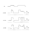
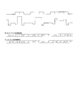
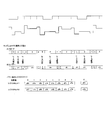
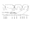
- FIG. 1 is a block diagram conceptually showing a basic configuration example of an LD driver according to an embodiment. It is a figure which shows an example of a write strategy. It is a figure which shows notionally the aspect of the transition between each state value in the LD driver which concerns on a present Example. It is a figure which shows an example of the write strategy by a conventional LD driver. It is a figure which shows an example of the write strategy by LD driver concerning a present Example. It is a figure which shows an example of the write strategy by LD driver concerning a present Example. It is a figure which shows an example of the write strategy by LD driver concerning a present Example. It is a figure which shows an example of the write strategy by LD driver concerning a present Example. It is a figure which shows an example of the write strategy by LD driver concerning a present Example. It is a figure which shows the aspect of addition of the superimposition current by the LD driver which concerns on a present Example.
- An embodiment according to the laser driving apparatus of the present invention is a laser driving apparatus that controls driving of an optical pickup including an irradiation unit that irradiates laser light with power corresponding to a set value, and sets the power of the laser light.
- a code input means for inputting a code for designating a state value for power, and a power value corresponding to the state value designated by the code for the power of the laser beam emitted by the irradiation means in response to the input of the code
- the power changing means for changing to and the code specifying a specific state value are input, the driving mode of the laser driving device is changed according to the state value specified by the next input code Control means for changing.
- the power value of the laser beam irradiated by the irradiation unit is determined according to the state value specified by the code input by the code input unit.
- a plurality of types of supply current levels for laser light irradiation in the irradiation means are prepared so as to correspond to the power value of the laser light to be irradiated. Then, a state value designated by code input is selected from the plurality of current levels by the power changing unit, so that the current level supplied to the irradiation unit is switched. According to such a configuration, the number of transmission lines can be reduced as compared with a case where a plurality of current levels are directly selected by the control signal.
- the code input is typically performed by a combination of signal value states of a plurality of binary logic signals (hereinafter referred to as code signals).
- each of the eight current levels is transmitted in three lines. It can be specified by line.
- the driving mode of the laser driving device is changed according to the input of the next code. Is done.
- a code that specifies a specific state value hereinafter referred to as a specific code
- the code that is input next hereinafter referred to as a selection code
- a process different from the determination of the corresponding state value is performed.
- the state change corresponding to the power value of the laser light as usual is not performed, but the change process of the driving mode of the laser driving device as described later is performed.
- the process of changing the driving mode of the laser driving device may be performed together with the determination of the state value corresponding to the power value of the laser beam as usual.
- the change in driving mode means, for example, a change in power value corresponding to each state value, a change in part or all of a register set that stores a combination of each state value and power value, and high-frequency superposition This is to indicate processing for changing various modes of operation in the laser driving device, including changing the mode of adding current and switching the reproduction mode.
- Each of these processes may be configured to be performed alone, or a plurality of processes may be configured to be performed collectively.
- the number of code signal transmission lines More power values can be selected without increasing the number of signals, and various write strategy patterns can be realized.
- the code that specifies the state value for selecting the power value of the laser beam of the irradiation unit is used, and the selection following the input of the specific code is performed.
- the mode of operation of the laser driving device is changed according to the input of the code. Therefore, without increasing the number of transmission lines used for code signal transmission, it is possible to select power values for realizing more diverse write strategies and to instruct operation change processing at a suitable timing. It becomes.
- One aspect of the embodiment of the laser driving apparatus is that, when the code that designates the specific state value is input, the control unit specifies the state that is specified by the code that is input next. In accordance with the value, the driving mode of the laser driving device is changed so as not to change the power of the laser beam irradiated by the irradiation unit from the power value corresponding to the specific state value.
- the code specifying the state value corresponding to one power value is determined as the above-mentioned specific code, and the subsequent code input (that is, selection code input)
- the state value transitions to the state value specified by the power value corresponding to the transitioned state value is not changed.
- a selection code is input following a specific code, it is specified by a power value or a specific code that is used during input of a separately prepared selection code, regardless of the state value specified by the selection code. The same power value as that corresponding to the state value is selected.
- the control unit when the code that specifies the specific state value is input, specifies the state that is specified by the code that is input next. According to the value, the driving mode of the laser driving device is changed so as to change the power value corresponding to the state value in the power changing means.
- the code specifying the state value corresponding to one power value is determined as the above-mentioned specific code, and the subsequent code input (that is, selection code input) When the state value transitions to the state value specified by, normally, a power value different from the power value specified by the state value is selected.
- the code specifying the state value B or the code specifying the state value C is the selection code, and the corresponding power value is changed.
- the determination that the state value B and the state value C are selection codes is determined by whether or not the state value D input prior to the selection code is a specific code.
- the power changing unit includes a plurality of the state values specified by the code and a plurality of the powers corresponding to the plurality of the state values.
- a register set for storing values, wherein at least one of the state values corresponds to a plurality of the power values in the register set, and the control means includes the code for designating the specific state value
- one of the corresponding power values is selected for the state values corresponding to a plurality of the power values in accordance with the state value specified by the next input code.
- a register in which the state value specified by the code signal and each power value constituting the write strategy corresponding to the state value are stored in association with each other.
- register set is intended to indicate a set of at least one or more such registers.
- a plurality of power values are associated with at least one state value stored in the register set.
- a plurality of registers are provided in which different power values are stored corresponding to at least one of the state values that can be designated by a combination of codes.
- a code for specifying a state value corresponding to one power value is determined as the above-mentioned specific code, and is specified by subsequent code input (that is, selection code input).
- the state value determines one power value to be selected when the state value associated with the plurality of power values is specified by the code.
- the power value to be changed when the code designating the state value A is input is determined as the power value PA1 or the power value PA2. More specifically, when the code that specifies the state value B is a specific code, the selection code that is input next specifies the state value C, and this corresponds to the next time the state value A is specified. When the power value PA1 is output as the power value and the selection code to be input next specifies the state value D, the power value PA2 is output as the corresponding power value when the state value A is specified next. Is controlled.
- the power changing unit includes a plurality of the state values specified by the code and a plurality of the powers corresponding to the plurality of the state values.
- the state value specified by the code signal and each power value constituting the write strategy corresponding to the state value are associated with each other and stored in the register.
- register set is intended to indicate a set of at least one or more such registers.
- a plurality of register sets in which a plurality of power values are stored in association with at least one set of state values are stored in association with each other.
- a plurality of registers are provided in which different power values are stored corresponding to all state values that can be specified by a combination of codes.
- a code for specifying a state value corresponding to one power value is determined as the above-mentioned specific code, and is specified by subsequent code input (that is, selection code input). Depending on the state value, one set of power values corresponding to the state value specified by the subsequent code input is selected.
- This configuration makes it possible to switch a plurality of power values corresponding to the state values specified by each code at a time. Therefore, when recording is performed while switching between land recording and groove recording such as DVD-RAM, or when a specific linear velocity is reached in CAV (Constant-Angular-Velocity) recording, a plurality of power values are set once during data recording. It is possible to cope with the case where it is necessary to change to the above.
- CAV Constant-Angular-Velocity
- the state value designated by the specific code is made to correspond to the last power value of the recording mark portion or the power value of the cooling portion at the end, and switching is performed in the space portion.
- the laser driving device further includes superimposition adding means for adding a high-frequency superimposed current to the current for driving the laser driving device, and the control means sets the specific state value.
- the code to be specified is input, the presence / absence of addition of the superimposed current and the mode of addition of the superimposed current are controlled according to the state value specified by the next input code.
- the mode of addition of the high-frequency superimposed current added to the laser driving device is changed based on the state value specified by the selection code input following the specific code.
- the aspect of addition of the superimposed current is intended to indicate, for example, the magnitude of the amplitude of the superimposed current, the presence / absence of addition, and the like.
- a superimposed current of about several hundred MHz can be added in order to avoid an increase in noise mixed in the servo system of the laser diode in the irradiation means due to the return light from the recording layer of the disk. It has been implemented.
- the superimposed current is uniformly applied to the space portion.
- the recording pulse itself plays the same role as the superimposed current, while the From the point of view of interference, it may be advantageous not to irradiate the laser beam as much as possible.
- the state value specified by the specific code is made to correspond to the power value of the cooling unit arranged at the end of the recording mark unit, and the next input code (that is, the space unit)
- the next input code that is, the space unit
- the control unit when the code that specifies the specific state value is input, specifies the state that is specified by the code that is input next. According to the value, the driving mode of the laser driving device is switched to the reproduction mode, In the reproduction mode, the power changing unit changes the power of the laser beam to the predetermined power value, and changes the power of the laser beam irradiated by the irradiation unit according to the input of the code. It does not change.
- a rewritable optical disc such as a DVD-RW generally has a laser power higher than a laser power during normal data reproduction (so-called “so-called”) even in a space portion where a recording mark is not formed.
- Rewriting of data is realized by irradiating laser light with (Erase power).
- the “recording mode” in this embodiment typically performs data recording by alternately generating such erase power that mainly forms a space portion and write pulses that mainly form a mark portion. The purpose is to indicate the state.
- the code input means inputs the code by combining and inputting a plurality of signals taking binary signal values, and the code input means In the input, only one of the signal values in the plurality of signals changes from the previous code input.
- the transition between the state values is limited, the transition between the corresponding power values is also limited, and there is a technical problem that the write strategy pattern that can be expressed also decreases.
- the code input unit is configured to input the code by combining the plurality of signals and inputting as a gray code. May be.
- the state value and the power value are preferably associated with each state of the code signal, and the transition between the state values is performed. It becomes possible to carry out suitably.
- the transition between the state values is limited as described above, when the code designating the specific state value is input, the next input of the code is performed immediately before. It may be configured such that a change occurs in one or more signal values in the plurality of signals with respect to the input of the code.
- the signal value in the input of the next code (that is, the selection code) after the specific code is input, there is a restriction that the signal value can be changed only for one signal at one timing as described above.
- the state value may be shifted.
- each state value indicated by the Gray code is a state in which transition can be performed only for the other three state values.
- the state value that can be shifted from the state value 0 indicated by the gray code is the state value 1 (0, 0, 1).
- State value 3 (0, 1, 0) and state value 7 (1, 0, 0).
- the transition restriction is removed after the input of the specific code is confirmed, and the transition from this state is the laser to be output during the selected code when the input code is no longer the specific code. This is because it is uniquely determined under the condition of transition to a state value corresponding to power.
- control means is configured such that, when the code designating the specific state value is input, the laser driving apparatus according to the subsequent input of the code When the state value for return is specified by the input of the code, the driving mode of the power changing unit is restored according to the subsequent input of the code.
- a code that designates one state value is determined as the above-described specific code, and a code that designates a state value different from the above-described specific code is basically returned to the return code after the specific code.
- a return code a code that designates a state value different from the above-described specific code is basically returned to the return code after the specific code.
- the code that specifies the state value for return when the code that specifies the specific state value is input, when the subsequent code is input, when the state value for the return is designated, the input of the code for specifying the state value for the return is one of the plurality of signals with respect to the input of the previous code. Two or more signal values may be changed.
- the transition of the state value may be performed by removing the restriction that the signal value can be changed for only one signal at the timing.
- the code for specifying the specific state value may be configured to further comprise designation means capable of setting at least one of the codes inputted after the code is designated to designate the state value.
- At least one can be specified.
- the code input means inputs a timing signal that specifies a timing to apply the state value specified by the code in addition to the input of the code. Then, the power changing unit changes the power of the laser beam irradiated by the irradiation unit in accordance with the input of the code at a timing specified by the timing signal.
- the timing signal specifying the timing for applying the state value specified by the code input is used.
- timing signals may specify the application timing of the specified state value for all codes, and for example, only input of a certain code such as a specific code or a selection code may be performed. It may be configured to be implemented.
- An embodiment of the signal processing circuit of the present invention is connected to various aspects of the embodiment of the laser driving device described above, and includes a code signal supply unit that supplies a code signal indicating the code to the code input unit. Prepare.
- the above-described code signal can be suitably supplied. If comprised in this way, each effect of the laser drive device mentioned above can be enjoyed suitably.
- the embodiment according to the information recording apparatus of the present invention includes the above-described embodiment according to the laser driving apparatus of the present invention.
- the information recording apparatus of the present invention it is possible to suitably record information on an information recording medium such as an optical disk while enjoying the effects of the laser driving apparatus described above.
- the laser driving apparatus includes the irradiation unit, the code input unit, the power changing unit, and the control unit.
- the signal processing circuit according to the present embodiment includes code signal supply means.
- the information recording apparatus includes the laser driving apparatus according to the present embodiment. Therefore, it is possible to realize a write strategy corresponding to more laser power while keeping the signal transmission line for changing the amount of supplied current as small as possible.
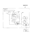
- FIG. 1 is a block diagram conceptually showing the structure of an LD driver 10 which is an example of the laser driving device in this embodiment.
- the LD driver 10 is typically provided inside the optical pickup 52 (see FIG. 15), and is connected to a laser diode LD (Laser Diode) 40 that is also provided in the optical pickup 52. Therefore, the LD driver 10 can control the laser power for laser light irradiation of the LD 40 according to the laser power in the write strategy, as will be described in detail later.
- the LD driver 10 is typically connected to a signal processing circuit 20 provided on a main board on which the optical pickup 52 is provided. For this reason, it is possible to receive an input of a code signal and a timing signal while receiving control such as clock management from the outside.
- the LD driver 10 decodes an input code signal to acquire a state value, and determines a state value and laser power specified by the decoded code signal.
- Register sets 12a and 12b that are stored in association with each other, a specific code selection unit 13a that detects a specific code based on a state value specified by a decoded code signal, and detection of a return code
- a return code selection unit 13b to be performed a command period control unit 14 for detecting the reception timing of the selection code specified by the specific code and the return code, and a command based on the selection code input during the reception timing of the selection code is output
- a command interpreter 15 that performs the register selection according to the selection code.
- An output selection unit 17 that selects an output power value designated by a command, a DA converter (Digital Analog Converter) 19 for outputting the power value to the laser diode 40, and an output buffer 20. .
- a DA converter Digital Analog Converter
- a code signal for determining the power value of the irradiation laser beam in the laser diode 40 is received, and various operations are performed according to the combination of the code signals. Is controlled to be performed. More specifically, when a code signal is input after a specific code is input and before a return code is input, the code is interpreted as a selection code.
- the selection code can be interpreted as a command for instructing various operations related to driving of the LD driver 10 in addition to a command for determining a power value stored in the register set.
- the decoder 11 is a specific example of “code input means” in the present embodiment, and is connected to a recording signal generator 21 that generates a code signal in the signal processing circuit 20 and receives an input of the code signal. Therefore, the decoder 11 typically acquires a signal state value by decoding a code signal input by a plurality of transmission lines. In the present embodiment, as shown in FIG. 1, a mode in which eight state values are expressed by combining three signal values transmitted by three transmission lines will be described.
- the code signal is preferably transmitted using two signal lines for one code signal and using a known differential transmission method. On the other hand, it may be configured to be performed by a single end method using one signal line for one code signal.
- the register sets 12a and 12b are a group of so-called registers that store state values that may be specified by code signals and power values corresponding to the state values in association with each other. Each state value is typically stored in association with a single power value, respectively.
- a plurality of register sets for example, the register set 12a and the register set 12b for associating different power values with one state value or a set of state value groups may be provided.
- the specific code selection unit 13a receives a state value specified by the code signal processed by the decoder, and when a code that is a specific code is detected, a signal that notifies the command period control unit 14 of the detection Is output.
- the return code selection unit 13b receives an input of a state value similarly designated by a code signal, and outputs a signal to that effect to the command period control unit 14 when a code that is a return code is detected.
- the specific code and the return code are intended to indicate a code that specifies a specific value among state values that can be specified by code input. Such a specific value may be stored in a register provided in advance, or may be appropriately determined by an external input such as the CPU 54 or some other means.
- the command period control unit 14 receives input of a signal indicating that the specific code and the return code are input, and manages the reception timing of the selection code. More specifically, when an input of a specific code is detected in the specific code selection unit 13a, each unit is controlled so that it is treated as a selection code with respect to a code input at a subsequent timing. When the input of the return code is detected in the code selection unit 13b, the subsequent codes are treated as normal codes (in other words, the power values are selected from the register sets 12a and 12b) instead of the selection codes. Control each part so that
- the selection code is a code input via the decoder 11 and is not a normal command for selecting a power value corresponding to the state value from the register set 12a or 12b, but in the command interpreter 15. It is intended to indicate a code that can typically be interpreted as a command indicating another operation.
- the command interpreter 15 receives an input of a state value specified by a code input from the decoder 11 in a state where it is specified by the operation of the command period controller 14 that the selection code is received.
- the command corresponding to each state value is selected and output to the output selection unit 17. The command selected here will be described in detail later.
- the command unit powers A16a and B16b are registers in which predetermined power values are stored, and are different from the power values stored in the register sets 12a and 12b depending on the selection command interpreted by the command interpretation unit 15 ( For example, when PSa or PSb) is determined, the power value is output to the output selection unit 17.
- the power value at this time may be the same power value as that stored in the register set 12a or 12b.
- the output selection unit 17 normally receives the power value determination signal from the register sets 12 a and 12 b and outputs it to the DA converter 19. On the other hand, the output selection unit 17 is controlled to process the command from the command interpretation unit 15 when the command period control unit 14 designates the selection code reception timing. Further, when a power value stored in the command unit power A 16 a or B 16 b is specified by a command, the input of the power value is received and output to the DA converter 19.
- the DA converter 18 is configured to receive a signal indicating a power value from the output selection unit 17, convert the signal to analog, and output the signal to the laser diode 40 via the output buffer 19.
- the recording signal generator 21 is a specific example of the “code signal supply means” according to the present invention, and is typically connected to the decoder 11 as described above to generate and supply a code signal. Do.
- the power value to be output to the laser diode 40 upon receiving the code input is determined, and at the selected code reception timing, the code input is interpreted as a command.
- the command that is interpreted and specified in the section 15 is executed.
- write strategies for recording data can be classified into several types according to the state of power value change in one sequence.
- write strategies for example, L-type, multi-pulse type, and castle type write strategies are known.
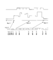
- FIG. 2 is a diagram showing an example of such a write strategy.
- Each write strategy is configured by combining a recording power value according to each mark length in a mark portion (that is, a portion where the NRZI signal value is high) indicated by an NRZI (Non Return to Zero Inversion) signal shown in the upper part. Has been.
- each power value constituting the write strategy is designated by eight state values designated by three code signals that can take binary values, and output to the laser diode 40. Will be described in particular.
- FIG. 3 is a diagram conceptually illustrating the relationship between the eight state values according to the present embodiment and the power values corresponding to the respective state values, and the mode of transition between the respective state values.
- the code input according to the present embodiment uses a combination of three code signals that can take a binary value as a gray code, thereby specifying a state value and corresponding to a power value. It is attached.
- a power value p0 is associated with a gray code state 0 (that is, a state in which three code signal values are 0, 0, 0).
- a gray code state 0 that is, a state in which three code signal values are 0, 0, 0.
- each state value can only transit to three adjacent state values (for example, from state 0 to state 1, state 3, and state 7).
- the command specified by the selection code includes one in which the transition of the state value is performed without such a restriction on the transition.
- FIGS. 4 to 6 are diagrams showing the state value and the power value specified in the input code for realizing the write strategy, respectively.
- the write strategy shown in FIG. 4 is composed of a combination of eight different power values. Therefore, when a random code that is not provided with the restriction on transition between the state values described above is used, the write strategy is expressed by eight state values. On the other hand, according to the Gray code according to the above-described transition rule, although there are eight state values, there is a restriction on the transition between each other, so the write strategy cannot be fully expressed (the state value is indicated by an asterisk). See section).
- FIG. 5 is a diagram illustrating a mode of expressing a write strategy in a configuration using a random code.
- a write strategy comprising a combination of eight power values similar to that in FIG. 4 is shown.
- the state value designated by the input code and the power value corresponding to the state value are shown in the lower part.
- the relationship between the state value stored in the register set 12a or 12b and the power value is shown.
- the power value pS indicates a power value output from the register 16a or 16b in which the command unit power is stored by a command specified by the selection code.
- state value 0 is set as a specific code
- state value 2 is set as a return code
- a command is set so that the power value pS is output regardless of the originally specified state value.
- one of the three associated power values is selected in the code specifying the state value 2 to be input next. . That is, when the state value indicated by the selection code is the state value 4, p2c is selected as the power value corresponding to the next state value 2, and when the state value 3 is specified by the selection code, the next state For value 2, when power value p2b is selected and state value 1 is specified by the selection code, for next state value 2, power value p2a is selected.
- FIG. 6 is a diagram showing a mode of expressing a write strategy in a configuration using a gray code in which a restriction is imposed on transitions between state values.
- the state value 0 is set as the specific code, and the state value 6 is set as the return code.
- the power value pS is output for the selection code regardless of the original state value, and the power value corresponding to the state value 6 is determined by the state value specified in the selection code. Is selected.
- the transition of the state value is configured such that each state value represented by the code signal value can be changed to only one signal value at one timing.
- each state value is configured such that, in the Gray code, a transition can be made only to a state value in which any one signal value in a plurality of signals is different. For this reason, the degree of freedom of the write strategy that can be expressed is reduced even if the code input has the same number of state values as compared with the random code.
- the input of the selection code following the input of the specific code and the input of the return code following the input of the selection code it is configured to be able to transition to an arbitrary state value outside the gray code transition rule described above. Also good. For example, in the example shown in FIG. 6, in the next selection code input in which the state value 5 is specified by the specific code, the state value 0 that cannot be changed is specified in the gray code restriction rule. There is a part.
- the reason that the gray code transition restriction may be removed is that the power value is pS regardless of what code is input in the selected code. In other words, after the specific code is detected, it is sufficient to always output pS when the input code becomes a code other than the specific code. Therefore, even if a plurality of signal lines change, it is not necessary to wait for all signals to be established, and the output transition is determined by the earliest signal change among them. Accordingly, by strictly managing the input timing for at least one signal, it is possible to appropriately manage the timing for changing the state value.
- a write strategy composed of a combination of eight power values can be expressed by using fewer state values.
- the output of the power value stored in the command part power and the selection of a plurality of power values corresponding to other state values can be made.
- Various write strategies can be realized with a small number of state values.
- FIG. 7 is a diagram illustrating a mode of expressing a write strategy in a configuration using a random code.
- two register sets 1 and 2 are provided in which different power values are associated with the state values 1 to 7, respectively.
- a register for storing two kinds of power values is also provided for the command part power output by the command specified in the selection code.
- the power values pSa and pSb may be configured so that the power value to be output is appropriately switched by a register set switching operation to be described later, or a single power value regardless of the selected register set. May be output.
- the state value 5 is set as the specific code and the state value 1 is set as the return code.
- the power value pSa or pSb is output based on the currently selected register set, and the register set is determined according to the state value specified in the selection code. 1 or 2 is selected. More specifically, when the state value 0 is specified by the selection code, in the subsequent code input, the power value corresponding to the state value is selected from the register set 1 (that is, the power values p0a to p7a), and the state When the value 2 is designated, in the subsequent code input, the power value corresponding to the state value is selected from the register set 2 (that is, the power values p0b to p7b).
- power values corresponding to a plurality of state values can be switched at a time.
- the mode of the high-frequency superimposed current added to the LD driver 10 is controlled by the selection code.
- a superimposed current of about several hundred MHz is added to the drive current.
- it is preferable that such a current is not superimposed upon recording on the mark portion.
- the conventional LD driver When the conventional LD driver is configured to change the manner in which the superimposed current is added, it is necessary to further provide a dedicated control signal, which may increase the number of transmission lines.
- the recording mark is set so that the code specifying the state value corresponding to the power value for irradiation to the space portion (so-called reproduction power or erase power) becomes the selection code.
- a code for designating a state value corresponding to the last power value of the unit (typically, so-called cooling power) is set as the specific code.
- the manner of adding the superimposed current in the next space portion is determined. For example, in the example shown in FIG. 8, when the state value specified by the selection code is 2, the superimposed current is not added in the next space portion, and on the other hand, the state value specified by the selection code is 0. In such a case, the superimposed current is added to the next space portion.
- the selection code may be configured to change, for example, the amplitude of the high-frequency superimposed current in addition to the presence or absence of the superimposed current.
- the presence / absence of superimposition is controlled for each space portion, but the superimposition current is changed between the reproduction mode and the recording mode by the same technique as switching between the reproduction mode and the recording mode described later. You may make it change the aspect of addition.
- the driving mode of the LD driver 10 may be switched between the reproduction mode and the recording mode by a selection code.
- the recording mode typically means that a power value corresponding to a state value specified by code input is applied, and data recording is performed by irradiating laser light with various laser powers.
- the reproduction mode is typically intended to indicate a state in which irradiation is performed with a constant laser power during reproduction regardless of a state value specified by code input. .
- the mode to be applied at the timing when the selection code is input next is determined by the state value specified by the selection code. For example, in the example shown in FIG. 9, when the status value designated by the selection code is 2, the recording mode is applied at the next selection code input timing, while the status value designated by the selection code is 0. In this case, the playback mode is applied at the next selection code input timing.
- switching between the reproduction mode and the recording mode can be performed without increasing the transmission line.
- a predetermined laser power is typically output regardless of the state value.
- the laser power associated with the state value transition can be reduced. It is possible to input a specific code or a selection code without considering the change.
- a command such as a change of the driving mode of the LD driver 10 may be designated according to the input of the selection code.
- various commands can be specified using only the code input transmission line for changing the laser power without using the original command input transmission line. As a result, it is possible to control the driving of the suitable LD driver 10 without increasing the number of transmission lines.
- the expression of the write strategy composed of power values equal to or more than the number of state values is achieved without increasing the number of transmission lines. It becomes possible.
- FIGS. 11 and 12 there is provided a register set in which a plurality of power values are stored in association with one state value. And, as in the example described above, in the command specified by the input of the selection code, the power value corresponding to the state value is switched to express more power values than the number of state values. Is possible.
- the code specifying the state value 0 is set as the specific code, and the state values 2, 5 and 5 associated with the plurality of power values according to the state value specified in the selection code 7, the applied register set 1 or 2 is switched.
- the code specifying the state value 0 is set as the specific code, and the state values 2 and 5 associated with the plurality of power values are set according to the state value specified in the selection code.
- the applied register set 1 or 2 is switched, and the power value pS is designated when the selection code is input regardless of the state value of the selection code.
- state value whose power value is switched by inputting a selection code may be appropriately determined based on some means.
- a state value (that is, a state value specified by input of a return code that follows, in accordance with a state value specified by input of a selection code following input of a specific code that specifies state value 0)
- the power value corresponding to the state value 2 has been changed.
- FIG. 13 and FIG. 14 show that in the configuration according to the present embodiment, the same write strategy can be expressed by different configurations by changing the state value subjected to the change of the power value by the selection code. .
- FIGS. 13 and 14 can be performed in the same hardware configuration. It is possible to express a variety of write strategies.
- the transition of the state value is configured such that each state value represented by the code signal value can be changed to only one signal value at one timing.
- each state value is configured such that, in the Gray code, a transition can be made only to a state value in which any one signal value in a plurality of signals is different. For this reason, the degree of freedom of the write strategy that can be expressed is reduced even if the code input has the same number of state values as compared with the random code.
- FIG. 15 is a block diagram conceptually showing the basic structure of the information recording apparatus 1 in the example.
- the information recording apparatus 1 includes the optical pickup 52 including the above-described LD driver 10 and has at least a function of recording data on the mounted optical disc 100.
- the information recording apparatus 1 includes a disk drive 50 on which an optical disk 100 is actually loaded and data is recorded, and a host computer 30 such as a personal computer that controls data recording on the disk drive 50. And.
- the disk drive 50 includes an optical disk 100, a spindle motor 51, an optical pickup (PU) 52, a signal recording / reproducing unit 53, a memory 54, a CPU 55, an input / output control unit 56, and a bus 57.
- the host computer 30 includes an operation / display control unit, an operation button, a display panel, a CPU, a memory, an input / output control unit, a bus, and the like (not shown).
- the spindle motor 51 rotates and stops the optical disc 100, and operates when accessing the optical disc 100. More specifically, the spindle motor 51 is configured to rotate and stop the optical disc 100 at a predetermined speed while receiving spindle servo from a servo unit or the like (not shown).
- the optical pickup 52 includes, for example, a laser diode (LD) 40, the LD driver 10 described above, a photo detector (PD) 41, a collimator lens and an objective lens (not shown). It is prepared for. More specifically, at the time of data recording, the laser diode 40 irradiates the optical disc 100 with the laser beam LB while changing the power under the control of the LD driver 10. At this time, the LD driver 10 generates a drive signal, for example, for realizing the write strategy as described above, and drives the laser diode 40. As a result, a data pattern corresponding to the data is formed on the recording surface of the optical disc 100.
- a drive signal for example, for realizing the write strategy as described above
- the signal recording / reproducing unit 53 performs recording on the optical disc 100 by controlling the operations of the spindle motor 51 and the optical pickup 52 under the control of the CPU 54. More specifically, the signal recording / reproducing unit 53 is configured by, for example, a head amplifier. The head amplifier amplifies the output signal of the photodetector 41 provided in the optical pickup 52 (that is, a signal indicating the reflected light of the laser light and the read signal), and outputs the amplified signal. Further, the signal recording / reproducing unit 53 receives input of information and recording data related to the optical disc 100 from the host computer 30 described later, and outputs the information to the LD driver 10.
- the CPU 54 is connected to the signal recording / reproducing unit 53, the memory 55, and the input / output control unit 56 via the bus 57, and gives instructions to the signal recording / reproducing unit 53, the memory 55, and the input / output control unit 56, so 50 overall control.
- software or firmware for operating the CPU 54 is stored in the memory 55.
- the memory 55 is a buffer area for data used for recording operations and the like, and an area used as an intermediate buffer for conversion into data that can be used by the signal recording / reproducing unit 53.
- the memory 55 is used in general data processing in the disk drive 50. Is done.
- the memory 55 stores a ROM area in which a program (that is, firmware) for operating the information recording apparatus 1 is stored, and data used for a recording operation is temporarily stored, and is necessary for the operation of the firmware and the like.
- RAM area for storing various variables and the like.
- the input / output control unit 56 controls data input / output from the outside to the disk drive 50.
- a drive control command issued from an external host computer 30 connected to the disk drive 50 via an interface such as SCSI or ATAPI is transmitted to the CPU 54 via the input / output control unit 56.
- data used for the recording operation is exchanged with the host computer 30 via the input / output control unit 56.
- a specific example of the information recording apparatus 1 described above is a disk drive that records data under the control of a host computer 30 such as a known personal computer or workstation.
- a host computer 30 such as a known personal computer or workstation.
- it is a household device such as a recorder device that records video.
- the recorder device includes a disk drive unit and a control unit for controlling the disk drive unit, and the control unit corresponds to the host computer shown in FIG.
Landscapes
- Physics & Mathematics (AREA)
- Optics & Photonics (AREA)
- Optical Recording Or Reproduction (AREA)
- Optical Head (AREA)
Abstract
設定値に応じたパワーでレーザ光を照射する照射手段40を備える光ピックアップ52の駆動を制御するレーザ駆動装置10は、レーザ光のパワーを設定するための状態値を指定するコードを入力するコード入力手段11と、コードの入力に応じて、照射手段が照射するレーザ光のパワーを該コードによって指定される状態値に対応するパワー値へと変更するパワー変更手段12a、12bと、特定の状態値を指定するコードが入力される場合、次に入力されるコードによって指定される状態値に応じて当該レーザ駆動装置10の駆動の態様を変更する制御手段15とを備える。
Description
本発明は、光ディスクなどの情報記録媒体に対しレーザ光を照射することで情報の記録を行う情報記録装置に備えられ、レーザ光の出力を変動させつつ照射を行うよう制御するレーザ駆動装置、該レーザ駆動装置に備えられる信号処理回路及び該レーザ駆動装置が備えられる情報記録装置の技術分野に属する。
例えば光ディスクなどの情報記録媒体においては、レーザダイオードから光ディスクに向けてレーザ光が照射されることで、該光ディスク上に記録マークないしは記録ピットが形成される。これにより、光ディスクにデータが記録される。レーザダイオードには、該レーザダイオードが動作するために必要な動作電圧が印加されるように、電源から一定の電源電圧が供給されている。そして、レーザダイオードから照射されるレーザ光は、トランジスタ等を含むレーザドライバ回路の動作により、その波形やパワーが制御される。特に、多値レベル化及びパルス分割されたレーザ光の波形やパワーのパターンをライトストラテジと言う。
このようなライトストラテジを実現するためには、高速且つ連続的に変化するパルス化されたレーザ光の波形及びパワーを制御することが必要であり、従来、様々な手法が用いられている。
例えば、レーザダイオードに対し、複数通りのパワーのレーザ光を照射させるための電流を供給する複数の電流源を備え、その電流源にそれぞれ対応する制御信号の入力により電流源からの電流の供給を直接切り替えることでレーザダイオードへの供給電流を変化させ、レーザダイオードのレーザ光のパワーを変化させる、所謂コンベンショナル型と呼ばれる手法がある。
また、特許文献1には、複数の制御信号を組み合わせることで様々な状態値を指定するコードを入力し、該状態値に対応してレーザダイオードのレーザパワーを変更する構成が開示されている。
複雑なライトストラテジの表現を実現するにあたっては、より多くのパワー値を表現可能であることが好ましい。その一方で、パワー値を表現するための入力信号の増加は、光ピックアップとドライブ本体との間の伝送ラインの増加に繋がり、配線領域の拡大、配線の屈曲部における可塑性の低下、接続コネクタピン数増加などに起因するコストの上昇、及び配線部からの不要輻射増大などの種々の技術的な問題を引き起こす可能性がある。特に、最近用いられる伝送ラインにおいては、高速な信号伝送を可能とするために、一の伝送ラインに二本の信号線を用いた差動信号方式が採用されることが多く、一の入力信号の増加が、二本の配線増加となるため、更に上述した影響が大きくなる。
上述したコンベンショナル型の方法によれば、ライトストラテジの表現のために、ライトストラテジを構成するパワー値の数と同数の制御信号が必要となるため、複雑なライトストラテジに対応しようとすると、膨大な数の伝送ラインが必要となるという技術的な問題がある。
また、特許文献1に記載されるコードを用いた構成によれば、伝送ラインの数に対する表現可能な状態値の数は増加するものの、それでもまだライトストラテジに応じて、伝送ラインが増加する可能性がある。
本発明は、例えば上述した従来の問題点に鑑みなされたものであり、供給電流量を変更させるための信号の伝送ラインを極力少なく保ちつつ、より多くのレーザパワーより構成されるライトストラテジを表現し得るレーザ駆動装置を提供することを課題とする。
上記課題を解決するために、本発明のレーザ駆動装置は、設定値に応じたパワーでレーザ光を照射する照射手段を備える光ピックアップの駆動を制御するレーザ駆動装置であって、前記レーザ光のパワーを設定するための状態値を指定するコードを入力するコード入力手段と、前記コードの入力に応じて、前記照射手段が照射する前記レーザ光のパワーを該コードによって指定される前記状態値に対応するパワー値へと変更するパワー変更手段と、特定の状態値を指定する前記コードが入力される場合、次に入力される前記コードによって指定される前記状態値に応じて当該レーザ駆動装置の駆動の態様を変更する制御手段とを備える。
上記課題を解決するために、本発明の信号処理回路は、上述のレーザ駆動装置に接続され、前記コード入力手段に対して、前記コードを示すコード信号を供給するコード信号供給手段を備える。
上記課題を解決するために、本発明の情報記録装置は、上述のレーザ駆動装置を備える。
本発明の作用及び他の利得は次に説明する実施の形態から明らかにされよう。
1 情報記録装置、
10 LDドライバ、
11 デコーダ、
12a、12b レジスタセット、
13a 特定コード選択部、
13b 復帰コード選択部、
14 コマンド期間制御部、
15 コマンド解釈部、
16a、16b コマンド部パワーレジスタ、
17 出力選択部、
18 DAコンバータ、
20 出力バッファ、
21 記録信号発生部、
30 ホストコンピュータ、
40 レーザダイオード、
50 ディスクドライブ、
54 CPU、
100 光ディスク
10 LDドライバ、
11 デコーダ、
12a、12b レジスタセット、
13a 特定コード選択部、
13b 復帰コード選択部、
14 コマンド期間制御部、
15 コマンド解釈部、
16a、16b コマンド部パワーレジスタ、
17 出力選択部、
18 DAコンバータ、
20 出力バッファ、
21 記録信号発生部、
30 ホストコンピュータ、
40 レーザダイオード、
50 ディスクドライブ、
54 CPU、
100 光ディスク
本発明のレーザ駆動装置に係る実施形態は、設定値に応じたパワーでレーザ光を照射する照射手段を備える光ピックアップの駆動を制御するレーザ駆動装置であって、前記レーザ光のパワーを設定するための状態値を指定するコードを入力するコード入力手段と、前記コードの入力に応じて、前記照射手段が照射する前記レーザ光のパワーを該コードによって指定される前記状態値に対応するパワー値へと変更するパワー変更手段と、特定の状態値を指定する前記コードが入力される場合、次に入力される前記コードによって指定される前記状態値に応じて当該レーザ駆動装置の駆動の態様を変更する制御手段とを備える。
本発明のレーザ駆動装置に係る実施形態によれば、コード入力手段によって入力されるコードによって指定される状態値に応じて、照射手段が照射するレーザ光のパワー値が決定される。
より具体的には、本実施形態のレーザ駆動装置においては、照射手段におけるレーザ光照射用の供給電流レベルが、照射するレーザ光のパワー値に対応するように複数通り用意されている。そして、該複数通りの電流レベルのうち、コード入力によって指定される状態値がパワー変更手段により選択されることで、照射手段へと供給される電流レベルが切り替わる。このような構成によれば、複数通りの電流レベルを制御信号で直接選択する場合に比較して、伝送ラインを減らすことが出来る。コード入力は、典型的には、複数の2値ロジック信号(以下、コード信号と記載)の信号値の状態の組み合わせによって行われる。
コードによって指定される状態値に応じて電流レベルを選択する場合、例えば、後述するように二値的な信号値を採り得るコード信号を用いれば、8通りの電流レベルの夫々を3本の伝送ラインで指定することが出来る。
更に、本発明のレーザ駆動装置に係る実施形態によれば、一のコードの入力によって特定の状態値が指定される場合、次のコードの入力に応じて、レーザ駆動装置の駆動の態様が変更される。言い換えれば、特定の状態値を指定するコード(以下、特定コードと記載)が入力される場合、次に入力されるコード(以下、選択コードと記載)は、通常通りのレーザ光のパワー値に対応する状態値の決定とは異なる処理が行われることになる。このとき、選択コードの入力に応じて、通常通りのレーザ光のパワー値に対応する状態値の決定を実施せずに、後述するようなレーザ駆動装置の駆動の態様の変更処理が実施されても良く、また、通常通りのレーザ光のパワー値に対応する状態値の決定とともに、レーザ駆動装置の駆動の態様の変更処理が実施されても良い。
ここに、駆動の態様の変更とは、例えば、各状態値に対応するパワー値の変更、各状態値とパワー値との組み合わせが格納されるレジスタセットの一部、または全部の変更、高周波重畳電流の付加の態様の変更、並びに再生モードの切替などを含む、レーザ駆動装置における種々の動作の態様を変更させる処理を示す趣旨である。これらの処理は、夫々単独で実施されるよう構成されていても良く、また、複数の処理がまとめて実施されるよう構成されていても良いものである。
例えば、特定コードの入力に続いて行われる選択コードの入力によって、各状態値に対応するパワー値の変更やレジスタセットの変更などが実施されるよう構成される場合、コード信号の伝送ラインの数を増やすことなく、より多くのパワー値を選択することが出来るようになり、多様なライトストラテジのパターンを実現することが可能となる。
また、各状態値に対応するパワー値の変更やレジスタセットの変更などの他、高周波重畳の付加の態様の変更や、再生モードの切替を行う場合など、ラッチ動作を伴うことで、動作速度が遅くなりがちになる。しかしながら、このような処理は典型的には、ライトストラテジにおけるデータ記録部(つまり、マーク部)の間の部分(所謂、スペース部)において行われること、更に、スペース部は必ず所定の長さ継続することなどから、上述したように特定コードの入力に続いて行われる選択コードの入力に応じて、これらの処理を行うことで、好適なタイミングにおける処理の実施を実現出来る。
以上、説明したように、本発明のレーザ駆動装置に係る実施形態によれば、照射手段のレーザ光のパワー値を選択するための状態値を指定するコードを用い、特定コードの入力に続く選択コードの入力に応じて、当該レーザ駆動装置の動作の態様が変更される。従って、コード信号の伝送に用いる伝送ラインの数を増やすことなく、より多様なライトストラテジを実現するためのパワー値を選択することや、好適なタイミングでの動作の変更処理を指示することが可能となる。
本発明のレーザ駆動装置に係る実施形態の一の態様は、前記制御手段は、前記特定の状態値を指定する前記コードが入力される場合、次に入力される前記コードによって指定される前記状態値に応じて、前記照射手段が照射する前記レーザ光のパワーを、前記特定の状態値に対応する前記パワー値から変更しないよう当該レーザ駆動装置の駆動の態様を変更する。
この態様によれば、ライトストラテジを構成するパワー値の変更において、一のパワー値に対応する状態値を指定するコードを上述の特定コードとして決定し、続くコード入力(つまり、選択コードの入力)によって指定される状態値へと状態値が遷移する場合、遷移した状態値に対応するパワー値への変更が行われない。言い換えれば、特定コードに続いて選択コードが入力された場合、該選択コードによって指定される状態値に依らず、別途用意した選択コード入力中に使用するパワー値、若しくは、特定コードによって指定される状態値と対応するものと同一のパワー値が選択されるよう構成される。
このように構成することで、選択コードの違いによるレーザ光のパワー値の変更を伴うことなく、コードによって指定される状態値のみを変更させることが出来る。従って、例えば、後述するように、コードの入力による状態値の遷移に制限が係る場合(例えば、コード信号を伝送する複数の伝送ラインでは、一のタイミングにおいて一の伝送ラインにおける信号値のみ変更され得る場合)、パワー値の変更を伴うことなく状態値を遷移し得ることで、より多様な状態値間の遷移のパターンを実現出来るようになる。
本発明のレーザ駆動装置に係る実施形態の他の態様は、前記制御手段は、前記特定の状態値を指定する前記コードが入力される場合、次に入力される前記コードによって指定される前記状態値に応じて、前記パワー変更手段における前記状態値に対応する前記パワー値を変更するよう当該レーザ駆動装置の駆動の態様を変更する。
この態様によれば、ライトストラテジを構成するパワー値の変更において、一のパワー値に対応する状態値を指定するコードを上述の特定コードとして決定し、続くコード入力(つまり、選択コードの入力)によって指定される状態値へと状態値が遷移する場合、通常該状態値によって指定されるパワー値とは異なるパワー値が選択される。
例えば、ある状態値Aを指定するコードの入力に先駆けて、他の状態値Bを指定するコードが入力された場合と、また別の状態値Cを指定するコードが入力された場合とでは、状態値Aに対応するパワー値が異なる。この例では、状態値Bを指定するコード、または状態値Cを指定するコードが選択コードとなって、対応するパワー値が変更される。
この時、状態値B及び状態値Cが選択コードであるという判別は、選択コードに先駆けて入力される状態値Dが特定コードであるかどうかにより決定される。
このように構成することで、コード信号の伝送に用いる伝送ラインの数を増やすことなく、より多様なライトストラテジを実現するためのパワー値を選択することが可能となる。尚、該構成によれば、より少ない状態値で多くのパワー値を表現することが出来るため、後述する状態値間の遷移に制限が設けられている態様において、特に有効に機能することとなる。
本発明のレーザ駆動装置に係る実施形態の他の態様は、前記パワー変更手段は、前記コードにより指定される複数の前記状態値と、該複数の前記状態値の夫々に対応する複数の前記パワー値とを格納するレジスタセットを更に備え、少なくとも一つの前記状態値は、前記レジスタセットにおいて複数の前記パワー値に対応しており、前記制御手段は、前記特定の状態値を指定する前記コードが入力される場合、次に入力される前記コードによって指定される前記状態値に応じて、複数の前記パワー値に対応する前記状態値について、対応する前記パワー値を一つ選択する。
この態様によれば、コード信号により指定される状態値と、該状態値に対応したライトストラテジを構成する各パワー値とが互いに関連付けられて格納されるレジスタが設けられる。尚、レジスタセットとは、少なくとも一つ以上のこのようなレジスタの集合を示す趣旨である。また、特にこの態様においては、レジスタセット内に格納される少なくとも一つの状態値に対して、複数のパワー値が関連付けられている。典型的には、コードの組み合わせによって指定され得る状態値のうち、少なくとも一つの状態値に対して、夫々異なるパワー値が対応されて格納される複数のレジスタが設けられる。
そして、ライトストラテジを構成するパワー値の変更において、一のパワー値に対応する状態値を指定するコードを上述の特定コードとして決定し、続くコード入力(つまり、選択コードの入力)によって指定される状態値によって、次に、該複数のパワー値と関連付けられている状態値がコードにより指定されたときに選択されるパワー値が一つ決定される。
例えば、レジスタセット内において、ある状態値Aに対し、パワー値PA1及びパワー値PA2が関連付けられて格納されている場合、特定コードの入力に続いて入力される選択コードが指定する状態値によって、次に状態値Aを指定するコードが入力された際に変更されるパワー値が、パワー値PA1またはパワー値PA2に決定される。より具体的には、状態値Bを指定するコードが特定コードであった場合、次に入力される選択コードが状態値Cを指定した場合、次に状態値Aが指定されたときに対応するパワー値としてパワー値PA1が出力され、他方、次に入力される選択コードが状態値Dを指定した場合、次に状態値Aが指定されたときに対応するパワー値としてパワー値PA2が出力されるよう制御される。
このように構成することで、コード信号の伝送に用いる伝送ラインの数を増やすことなく、より多様なライトストラテジを実現するためのパワー値を選択することが可能となる。尚、該構成によれば、より少ない状態値で多くのパワー値を表現することが出来るため、後述する状態値間の遷移に制限が設けられている態様において、特に有効に機能することとなる。
本発明のレーザ駆動装置に係る実施形態の他の態様は、前記パワー変更手段は、前記コードにより指定される複数の前記状態値と、該複数の前記状態値の夫々に対応する複数の前記パワー値とを格納する複数のレジスタセットを更に備え、前記制御手段は、前記特定の状態値を指定する前記コードが入力される場合、次に入力される前記コードによって指定される前記状態値に応じて、前記複数のレジスタセットのうち一つを選択する。
この態様によれば、コード信号により指定される状態値と、該状態値に対応したライトストラテジを構成する各パワー値とは、互いに関連付けられてレジスタ内に格納されている。尚、レジスタセットとは、少なくとも一つ以上のこのようなレジスタの集合を示す趣旨である。また、特にこの態様においては、少なくとも一組の状態値に対して、複数通りのパワー値が対応されて格納される複数のレジスタセットが関連付けられて格納されている。典型的には、コードの組み合わせによって指定され得る全ての状態値に対して、夫々異なるパワー値が対応されて格納される複数のレジスタが設けられる。
そして、ライトストラテジを構成するパワー値の変更において、一のパワー値に対応する状態値を指定するコードを上述の特定コードとして決定し、続くコード入力(つまり、選択コードの入力)によって指定される状態値によって、以降のコード入力により指定される状態値に対して、対応するパワー値のセットが一つ選択される。
このように構成することで、各コードにより指定される状態値に対応する複数のパワー値を一度に切り替えることが出来る。従って、DVD-RAMなどのランド記録とグルーブ記録を切り替えながら記録を行う場合や、CAV(Constant Angular Velocity)記録において特定の線速度に達した場合など、データの記録中に複数のパワー値を一度に変更する必要が生じる場合などに好適に対応することが出来る。
以上のことから、コード信号の伝送に用いる伝送ラインの数を増やすことなく、より多様なライトストラテジを実現するためのパワー値を選択することが可能となる。尚、該構成によれば、より少ない状態値で多くのパワー値を表現することが出来るため、後述する状態値間の遷移に制限が設けられている態様において、特に有効に機能することとなる。
また、レジスタセットの切替はデータの記録マーク形成中でないタイミングで行う方が好ましい。従って、好適には、特定コードにより指定される状態値を、記録マーク部の最後のパワー値または終了時のクーリング部のパワー値と対応させ、スペース部において切り替えが実施される。
本発明のレーザ駆動装置に係る実施形態の他の態様は、当該レーザ駆動装置を駆動する電流に高周波の重畳電流を付加する重畳付加手段を更に備え、前記制御手段は、前記特定の状態値を指定する前記コードが入力される場合、次に入力される前記コードによって指定される前記状態値に応じて、前記重畳電流の付加の有無、及び前記重畳電流の付加の態様を制御する。
この態様によれば、特定コードに続いて入力される選択コードによって指定される状態値に基づいて、レーザ駆動装置に付加される高周波重畳電流の付加の態様が変更される。ここに、重畳電流の付加の態様とは、例えば、該重畳電流の振幅の大小や、付加の有無などを示す趣旨である。
一般的な光ディスクの情報記録装置では、ディスクの記録層からの戻り光によって、照射手段におけるレーザダイオードのサーボ系に混入するノイズの増加を避けるため、数百MHz程度の重畳電流を付加することが実施されている。
例えば、高倍速のDVD-Rなどでは、このような重畳電流とライトストラテジ制御のための信号パルスが干渉することによって、記録パルスの劣化を招かないように、例えば、記録領域におけるスペース部分にのみ重畳電流を付加させるよう制御されている。
この時、従来型の構成によれば、スペース部には一様に重畳電流が付加されるが、例えば、比較的短いスペース部では、記録パルス自体が重畳電流と同様の役割をする一方、熱干渉の観点からは出来るだけレーザ光の照射を行わない方が有利な場合がある。
このように構成することで、例えば、特定コードにより指定される状態値を、記録マーク部の最後に配置されるクーリング部のパワー値に対応させ、次に入力されるコード(つまり、スペース部のパワー値を指定するコード)に指定される状態値に基づき、次のマーク部に続くスペース部での重畳電流の付加の態様を選択することが出来る。従って、伝送ラインの追加を行うことなく、重畳電流の付加の態様を好適に指示することが出来る。このため、例えば、長さの異なるスペース部の夫々に対して、異なる選択コードで重畳電流の付加の態様を決定することで、スペース部の長さに応じた重畳電流の付加の有無を指定することも出来る。
本発明のレーザ駆動装置に係る実施形態の他の態様は、前記制御手段は、前記特定の状態値を指定する前記コードが入力される場合、次に入力される前記コードによって指定される前記状態値に応じて、当該レーザ駆動装置の駆動の態様を再生モードへと切り替え、
該再生モードにおいては、前記パワー変更手段は、前記レーザ光のパワーを所定の前記パワー値へと変更するとともに、前記コードの入力に応じては、前記照射手段が照射する前記レーザ光のパワーを変更しない。
該再生モードにおいては、前記パワー変更手段は、前記レーザ光のパワーを所定の前記パワー値へと変更するとともに、前記コードの入力に応じては、前記照射手段が照射する前記レーザ光のパワーを変更しない。
この態様によれば、特定コードに続いて入力される選択コードによって指定される状態値に基づいて、再生モードと記録モードとの切り替えを実施することが出来る。
情報記録装置においては、DVD-RWなどの書換型の光ディスクに対しては、記録マークが形成されないスペース部であっても、一般的に通常のデータ再生時のレーザパワーよりも高いレーザパワー(所謂、イレースパワー)でのレーザ光の照射を行うことで、データの書換を実現している。この態様における「記録モード」とは、典型的には、このような主にスペース部を形成するイレースパワーと、主にマーク部を形成するライトパルスを交互に発生させることでのデータ記録を行う状態を示す趣旨である。
このときの再生パワーとイレースパワーとの切り替えにおいては、単にパワー値を変更するだけでなく、同時にサーボ系のゲインも切り替える必要が生じる。このため、従来型のレーザ駆動装置においては、十分な時間軸上での精度が確保されるように、専用の信号線を設けたり、ライトストラテジを指定する入力信号によって示されるパワー値のうちの一つを再生用パワーに対応させるよう構成されている。しかしながら、このような構成を備えることで、前者によれば、本体と光ピックアップ間の接続本数が増加してしまい、上述したような問題を引き起こしかねず、また、後者によれば、ライトストラテジ用のパワー値設定に用いることの出来る信号の状態数が低下してしまう。
このように構成することで、ライトストラテジに用いられるコードによって指定される状態値を用いたり、追加の伝送ラインを備えることなく、好適に再生モードと記録モードとの切り替えを実施することが出来る。
本発明のレーザ駆動装置に係る実施形態の他の態様は、前記コード入力手段は、二値的な信号値を採る複数の信号を組み合わせて入力することで前記コードの入力を行い、前記コードの入力においては、一つ前の前記コードの入力との間で、前記複数の信号におけるいずれか一つの前記信号値にのみ変化が生じる。
この態様によれば、コード入力によって指定される状態値間の遷移に制限が設けられる。例えば、二値的な値を採る複数の伝送ラインによって入力されるコード信号の状態に応じて、状態値が指定される態様においては、一のタイミングで一つの信号のみ信号値が変更し得るよう構成されている。
このように構成することで、一の状態値の遷移のタイミングは、一のコード信号の変化によってのみ指定されるため、厳密にレーザパワー変更などのタイミングを制御することが可能となる。
他方、状態値間の遷移が制限されることから、対応するパワー値間の遷移もまた制限され、表現可能なライトストラテジのパターンもまた低下してしまうという技術的な問題がある。しかしながら、本発明のレーザ駆動装置に係る他の実施形態を併せて用いることで、多様なライトストラテジの表現を可能としつつも、厳密なタイミング管理の可能なレーザ駆動装置を提供することが可能となる。
また、上述のように状態値間の遷移に制限が設けられている態様においては、前記コード入力手段は、前記複数の信号を組み合わせてグレイコードとして入力することで前記コードの入力を行うよう構成されていても良い。
このように構成すれば、一のタイミングで一つの信号のみ信号値が変更し得る構成において、コード信号の各状態に対し、好適に状態値やパワー値を対応させ、且つ状態値間の遷移を好適に行うことが可能となる。
更に、上述のように状態値間の遷移に制限が設けられている態様においては、前記特定の状態値を指定する前記コードが入力される場合、次の前記コードの入力においては、一つ前の前記コードの入力との間で、前記複数の信号における一つ以上の前記信号値に変化が生じるよう構成されていても良い。
このような構成によれば、特定コードが入力された次のコード(つまり、選択コード)の入力においては、上述したような一のタイミングで一つの信号のみ信号値が変更し得るとの制限を外れて、状態値の遷移が行われても良い。
例えば、二値的な信号値を取り得るコード信号を3本の伝送ラインで用いる場合、8通りの状態値が考えられる。しかしながら、一のタイミングで一つの信号値のみ変更され得るとの制限においては、グレイコードにより示される各状態値は、夫々他の3つの状態値に対してのみ遷移が行える状態である。言い換えれば、一の状態値Aから他の状態値Bへと遷移した場合、次に遷移し得る状態値は、状態値A、状態値C及び状態値Eの3つだけとなる。より具体的には、グレイコードにより示される状態値0(つまり、3本の伝送ラインの信号値がすべて0である場合)から遷移可能な状態値は、状態値1(0,0,1)、状態値3(0,1,0)及び状態値7(1,0,0)の3つだけとなる。このため、状態値の遷移、ひいては、ライトストラテジのパターンの表現にも制限が加えられることとなる。
そこで、上述したように特定コードと選択コードとの間で遷移の制限が外れるよう構成することで、グレイコードの遷移規則の制限を受けずに、特定コードの入力後に、任意の選択コードを入力することが可能となる。従って、更に多様なライトストラテジの表現が可能となる。
尚、このとき、遷移の制限が外れたとしても、もともと遷移の制限を行ったことにより享受し得る利点が失われることはない。遷移の制限が外れるのは、特定コードの入力が確認された後のことであり、この状態からの遷移は、入力コードが特定コードでなくなった場合、選択コードの期間中に出力されるべきレーザパワーに対応する状態値に遷移する、という条件のもと一意に決定されることに起因するためである。
本発明のレーザ駆動装置に係る実施形態の他の態様は、前記制御手段は、前記特定の状態値を指定する前記コードが入力される場合、以降の前記コードの入力に応じて当該レーザ駆動装置の駆動の態様を変更するとともに、前記コードの入力によって、復帰のための状態値が指定された場合、以降の前記コードの入力に応じては、前記パワー変更手段の駆動の態様を元に戻す。
この態様によれば、一の状態値を指定するコードを上述の特定コードとして決定し、該特定コード以降、基本的には上述の特定コードとは別の状態値を指定するコードを復帰のためのコード(以下、復帰コードと記載)が入力されるまで、入力されるコードは、全て選択コードとして扱われる。尚、このとき、入力されるコードにグリッジが含まれる場合、公知のグリッジ除去の手法が使用されることなどによって、グリッジによる影響が除去されることが好ましい。
従って、上述した各態様に記載されるような、特定コードに続く選択コードによって夫々指定される当該レーザ駆動装置の動作の変更の態様を連続して行うことが可能となる。
以上のことから、コード信号の伝送に用いる伝送ラインの数を増やすことなく、より多様なライトストラテジを実現するためのパワー値を選択することが可能となる。
また、上述のように復帰のための状態値を指定するコードが用いられる態様においては、前記特定の状態値を指定する前記コードが入力される場合、以降の前記コードの入力が行われる場合において、前記復帰のための状態値が指定される場合、該復帰のための状態値を指定する前記コードの入力においては、一つ前の前記コードの入力との間で、前記複数の信号における一つ以上の前記信号値に変化が生じるよう構成されていても良い。
このような構成によれば、復帰コードにより指定される状態値と、その一つ前に入力されたコード(つまり、選択コード)により指定される状態値との間では、上述したような一のタイミングで一つの信号のみ信号値が変更し得るとの制限を外れて、状態値の遷移が行われても良い。
このように構成することで、グレイコードの遷移規則の制限を受けずに、任意の状態値から、特定コードにより指定されるレーザ駆動装置の動作の態様が変更された状態から復帰するための復帰コードを入力することが可能となる。従って、更に多様なライトストラテジの表現が可能となる。
また、上述のように復帰のための状態値を指定するコードが用いられる態様においては、前記特定の状態値を指定する前記コード、前記復帰のための状態値を指定する前記コード、及び前記特定の状態値を指定する前記コードの入力以降に入力される前記コード、のうち少なくとも一つを設定することが可能な指定手段を更に備えるよう構成されていても良い。。
このような構成によれば、指定手段によって、特定コードにより指定される状態値、復帰コードにより指定される状態値、及び選択コードによって、対応するパワー値の選択が実施される状態値のうち、少なくとも一つを指定することが可能となる。
従って、一の一連の状態値の遷移において、上述した各状態値を適宜設定することで、互いに異なるライトストラテジを表現することが可能となる。よって、更に多様なライトストラテジの表現が可能となる。
本発明のレーザ駆動装置に係る実施形態の他の態様は、前記コード入力手段は、前記コードの入力に加えて、該コードにより指定される前記状態値を適用するタイミングを指定するタイミング信号を入力し、前記パワー変更手段は、該タイミング信号によって指定されるタイミングにおいて、前記コードの入力に応じて、前記照射手段が照射する前記レーザ光のパワーを変更する。
この態様によれば、上述した状態値を指定するコード入力のためのコード信号に加えて、該コード入力によって指定される状態値を適用するためのタイミングを指定するタイミング信号が用いられる。
このように構成すれば、例えば、上述したように、一のタイミングで一つの信号のみ信号値が変更し得るとの制限を外れて状態値の遷移が実施される場合などに対しても、厳密なタイミング管理を行うことが可能となる。
尚、このようなタイミング信号は、全てのコードに対して、指定される状態値の適用タイミングを指定しても良く、また、例えば、特定コードや選択コードなど、ある種のコードの入力のみが実施されるよう構成されていても良い。
本発明の信号処理回路に係る実施形態は、上述したレーザ駆動装置に係る実施形態の各種態様に接続され、前記コード入力手段に対して、前記コードを示すコード信号を供給するコード信号供給手段を備える。
本発明の信号処理回路に係る実施形態によれば、上述したコード信号を好適に供給することが出来る。このように構成すれば、好適に上述したレーザ駆動装置の各効果を享受することが出来る。
本発明の情報記録装置に係る実施形態は、上述した本発明のレーザ駆動装置に係る実施形態を備える。
本発明の情報記録装置に係る実施形態によれば、上述したレーザ駆動装置の各効果を享受しながら、例えば光ディスクなどの情報記録媒体に対し、好適に情報の記録を行うことが出来る。
以上説明したように、本実施形態に係るレーザ駆動装置によれば、照射手段と、コード入力手段と、パワー変更手段と、制御手段とを備える。本実施形態に係る信号処理回路によれば、コード信号供給手段を備える。本実施形態に係る情報記録装置は、本実施形態に係るレーザ駆動装置を備える。従って、供給電流量を変更させるための信号の伝送ラインを極力少なく保ちつつ、より多くのレーザパワーに対応したライトストラテジを実現出来る。
以下、本発明を実施するための最良の形態について図面を参照して説明する。
(1)基本構成例
始めに、図1を参照して、本発明の実施例に係るLDドライバ(Laser Diode Driver)10の基本的な構成について説明しながら、該LDドライバ10の基本的な動作について説明する。ここに、図1は、本実施例におけるレーザ駆動装置の一例であるLDドライバ10の構成を概念的に表すブロック図である。尚、LDドライバ10は、典型的には、光ピックアップ52(図15参照)の内部に設けられ、同じく光ピックアップ52内に設けられるレーザダイオードLD(Laser Diode)40に接続される。このため、LDドライバ10は、後に詳述するように、ライトストラテジにおけるレーザパワーに応じて、LD40のレーザ光照射のためのレーザパワーを制御することが出来る。また、LDドライバ10は、典型的には、光ピックアップ52が設けられる本体基板上に備えられる信号処理回路20と接続されている。このため、外部からの例えばクロック管理などの制御を受けつつコード信号やタイミング信号の入力を受けることが出来る。
始めに、図1を参照して、本発明の実施例に係るLDドライバ(Laser Diode Driver)10の基本的な構成について説明しながら、該LDドライバ10の基本的な動作について説明する。ここに、図1は、本実施例におけるレーザ駆動装置の一例であるLDドライバ10の構成を概念的に表すブロック図である。尚、LDドライバ10は、典型的には、光ピックアップ52(図15参照)の内部に設けられ、同じく光ピックアップ52内に設けられるレーザダイオードLD(Laser Diode)40に接続される。このため、LDドライバ10は、後に詳述するように、ライトストラテジにおけるレーザパワーに応じて、LD40のレーザ光照射のためのレーザパワーを制御することが出来る。また、LDドライバ10は、典型的には、光ピックアップ52が設けられる本体基板上に備えられる信号処理回路20と接続されている。このため、外部からの例えばクロック管理などの制御を受けつつコード信号やタイミング信号の入力を受けることが出来る。
図1に示されるように、LDドライバ10は、入力されるコード信号のデコード処理を行って状態値を取得するデコーダ11と、デコードされたコード信号により指定される状態値とレーザパワーを決定するためのパワー値とが互いに関連付けられて格納されるレジスタセット12a及び12bと、デコードされたコード信号により指定される状態値に基づき特定コードの検出を行う特定コード選択部13a及び復帰コードの検出を行う復帰コード選択部13bと、特定コード及び復帰コードにより指定される選択コードの受け付けタイミングを検出するコマンド期間制御部14と、該選択コードの受け付けタイミング中において入力される選択コードに基づくコマンドを出力するコマンド解釈部15と、該選択コードによってレジスタセットに保持される通常のパワー値とは異なるパワー値の出力が要求される場合に、該パワー値を出力するためのコマンド部パワーA16a及びコマンド部パワーB16bと、状態値や選択コードによって指定されるコマンドによって指定される出力パワー値を選択する出力選択部17と、該パワー値をレーザダイオード40に出力するためのDAコンバータ(Digital Analog Convertor)19と、出力バッファ20とを備えて構成される。
このようなLDドライバ10の動作によれば、基本的にはレーザダイオード40における照射レーザ光のパワー値を決定するためのコード信号の入力を受け、該コード信号の組み合わせに応じて、様々な動作が行われるよう制御される。より具体的には、特定コードが入力された後、復帰コードが入力されるまでの間に、コード信号の入力を受けた場合、該コードを選択コードとして解釈される。該選択コードは、レジスタセットに格納されるパワー値を決定するコマンドの他にも、LDドライバ10の駆動に係る各種動作を指示するコマンドとして解釈され得るものである。
以下に、本実施例に係るLDドライバ10の各部の動作や機能について詳しく説明する。
デコーダ11は、本実施例における「コード入力手段」の一具体例であって、信号処理回路20内においてコード信号の生成を行う記録信号発生部21に接続され、コード信号の入力を受ける。そこで、デコーダ11は、典型的には複数本の伝送ラインにより入力されるコード信号をデコードすることで、信号の状態値を取得する。本実施例においては、図1に示されるように、3本の伝送ラインにより伝送される3つの信号値を組み合わせることで、8通りの状態値を表現する態様について説明する。
尚、コード信号の伝送は、好適には、一のコード信号に対し二本の信号線を用い、公知の差動伝送方式などを用いて行われるよう構成されている。他方で、一のコード信号に対し一本の信号線を用いたシングルエンド方式で行われるよう構成されていても良い。
レジスタセット12a及び12bは、コード信号によって指定される可能性のある状態値と、該状態値に対応するパワー値とを互いに関連付けて格納する、所謂レジスタの一群である。各状態値は、典型的には、夫々単一のパワー値に関連付けられて格納されている。他方、一つの状態値、または一揃いの状態値群に対して、夫々異なるパワー値を関連付ける複数のレジスタセット(例えば、レジスタセット12a及びレジスタセット12b)が備えられていても良い。
特定コード選択部13aは、デコーダによって処理されたコード信号によって指定される状態値の入力を受け、特定コードとされているコードが検出された場合、コマンド期間制御部14へとその旨を伝える信号を出力する。他方、復帰コード選択部13bは、同じくコード信号によって指定される状態値の入力を受け、復帰コードとされているコードが検出された場合、コマンド期間制御部14へとその旨を伝える信号を出力する。尚、このような特定コード及び復帰コードとは、コード入力によって指定され得る状態値のうち、特定の値を指定するコードを示す趣旨である。このような特定の値は、あらかじめ設けられるレジスタなどに格納されていても良く、また、CPU54など、外部からの入力やその他何らかの手段により適宜決定されても良いものである。
コマンド期間制御部14は、特定コード及び復帰コード夫々の入力が行われたことを示す信号の入力を受け、選択コードの受け付けタイミングを管理する。より具体的には、特定コード選択部13aにおいて、特定コードの入力が検出された場合、以降のタイミングにおいて入力されるコードに対しては、選択コードとして扱われるよう各部を制御する、また、復帰コード選択部13bにおいて、復帰コードの入力が検出された場合、以降のコードに対しては、選択コードではなく、通常の(言い換えれば、レジスタセット12a、12bからパワー値を選択する)コードとして扱われるよう各部を制御する。
ここに、選択コードとは、デコーダ11を介して入力されたコードであって、レジスタセット12aまたは12bから夫々状態値に対応するパワー値を選択する通常のコマンドではなく、コマンド解釈部15において、典型的には他の動作を示すコマンドとして解釈され得るコードを示す趣旨である。
コマンド解釈部15は、典型的には、コマンド期間制御部14の動作によって、選択コードの受け付けタイミングであると指定されている状態において、デコーダ11よりコード入力により指定される状態値の入力を受け、該状態値に夫々対応するコマンドを選択し、出力選択部17へと出力する。ここで選択されるコマンドについては、後に詳述する。
コマンド部パワーA16a及びB16bは、所定のパワー値が格納されるレジスタであって、コマンド解釈部15において解釈される選択コマンドにより、レジスタセット12a、12bに格納されるパワー値とは異なるパワー値(例えば、PSaまたはPSb)が決定される場合、該パワー値を出力選択部17へと出力する。尚、このときのパワー値は、レジスタセット12aまたは12b内に格納されるものと同一のパワー値であっても良いものである。
出力選択部17は、通常はレジスタセット12a、12bからのパワー値決定信号を受け付けて、DAコンバータ19へと出力する。一方、出力選択部17は、コマンド期間制御部14によって選択コード受け付けタイミングであると指定されている場合においては、コマンド解釈部15からのコマンドを処理するよう制御される。また、コマンドによりコマンド部パワーA16aまたはB16bに格納されるパワー値が指定される場合には、該パワー値の入力を受け付け、DAコンバータ19へと出力する。
DAコンバータ18は、出力選択部17からパワー値を指示する信号の入力を受け、該信号をアナログ変換した後に出力バッファ19を介してレーザダイオード40へと出力する構成である。
また、記録信号発生部21は、本発明に係る「コード信号供給手段」の一具体例であり、典型的には、上述のようにデコーダ11へと接続されて、コード信号の生成及び供給を行う。
以上、説明したように、本実施例のLDドライバ10によれば、コード入力を受けてレーザダイオード40へと出力するパワー値を決定するとともに、選択コード受け付けタイミングにおいては、該コード入力がコマンド解釈部15において解釈され、指定されたコマンドが実行される。
(2)基本効果
続いて、図2から図7を参照して、本実施例に係るLDドライバ10を用いた具体的な効果について説明する。
続いて、図2から図7を参照して、本実施例に係るLDドライバ10を用いた具体的な効果について説明する。
一般的に、データの記録を行う際のライトストラテジは、一つのシーケンスにおけるパワー値の変化の様子によって幾つかのタイプに分類することが出来る。このようなライトストラテジの例として、例えば、L型、マルチパルス型、キャッスル型のライトストラテジが知られている。ここに、図2は、このようなライトストラテジの例を示す図である。
各ライトストラテジは、上段に示したNRZI(Non Return to Zero Inversion)信号によって示されるマーク部(すなわち、NRZI信号値が高い部分)において、各マーク長に応じて記録用のパワー値を組み合わせて構成されている。
本実施例においては、2値的な値を採り得る3つのコード信号により指定される8つの状態値によって、ライトストラテジを構成する各々のパワー値が指定されて、レーザダイオード40に出力される態様について特に説明する。
続いて、図3を用いて、本実施例に係るコード入力によるパワー値の指定の態様について説明する。図3は、本実施例に係る8つの状態値と、夫々の状態値に対応するパワー値との関係、及び各状態値間の遷移の態様について概念的に示す図である。
図3に示されるように、本実施例に係るコード入力は、2値的な値を採り得る3つのコード信号の組み合わせをグレイコードとして用いることで、夫々状態値を指定し、パワー値に対応付けられている。例えば、グレイコードの状態0(つまり、3つのコード信号値が0,0,0となる状態)に対しては、パワー値p0が対応付けられている。基本的に、このような状態値とパワー値との組み合わせは、レジスタセット12a、12bに夫々格納されている。
また、本実施例に係る各状態値間には、その遷移に制限が設けられている。つまり、複数の伝送ラインにより伝送されるコード信号において、一のタイミングにおいては一の信号値のみが遷移する。言い換えれば、一のコードが入力された次に入力されるコードは、該一のコードと信号値が一つ異なるものでなければならない。よって、図3に示される図においては、各状態値は夫々隣り合う3つの状態値(例えば、状態0からは、状態1、状態3及び状態7)にのみ遷移することが可能である。
これは、すなわち、一のコード入力タイミングでは、一の信号値の変化のタイミングにおいて新しい状態値が適用されることを示す。従って、ライトストラテジのためのパワー値の切り替えなど、比較的厳密なタイミング管理が必要となる場合において特に有効である。
尚、後に詳述するように、選択コードによって指定されるコマンドには、このような遷移の制限を外れて状態値の遷移が実施されるものも含まれる。
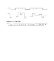
続いて、このようなグレイコードの入力による実際のライトストラテジの表現の態様について図4から図6を参照して説明する。ここに、図4から図6は、夫々ライトストラテジを実現するための入力コードに指定される状態値及びそのパワー値を示す図である。
まず、図4を参照して、従来型のレーザ駆動装置に係るパワー値の選択の態様について説明する。
図4に示されるライトストラテジは、夫々異なる8つのパワー値の組み合わせより構成されている。従って、上述した状態値間の遷移の制限が設けられていないランダムコードを用いた場合、8つの状態値によってライトストラテジが表現される。他方で、上述した遷移規則に従うグレイコードによれば、状態値は8つあるものの、互いの遷移に制限が設けられているため、ライトストラテジを表現しきれていない(状態値がアスタリスクで示される部分参照)。
次に上述するように、選択コードによるコマンド指定を可能とする本実施例に係るコードの入力によるライトストラテジの表現の態様について説明する。
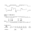
図5は、ランダムコードを用いる構成におけるライトストラテジを表現する態様を示す図である。図5の上段には、図4と同様の8つのパワー値の組み合わせから成るライトストラテジが、中段には、入力コードにより夫々指定される状態値と、該状態値に対応するパワー値が、下段には、このような構成において、レジスタセット12aまたは12bに格納される状態値とパワー値との関係が夫々示されている。
この構成によれば、状態値2に対して、3通りのパワー値(つまり、p2a、p2b及びp2c)が関連付けられている。また、パワー値pSとは、選択コードにより指定されるコマンドによって、コマンド部パワーが格納されるレジスタ16aまたは16bより出力されるパワー値を示す。
図5に示される例においては、状態値0が特定コードとして設定されているとともに、状態値2が復帰コードとして設定されている。
また、特定コードに続く選択コードの入力においては、本来指定される状態値に関わらず、パワー値pSが出力されるようコマンドが設定されている。更に、特定コードに続く選択コードの入力において指定された状態値に基づいて、次に入力される状態値2を指定するコードにおいて、対応付けられている3つのパワー値のうち1つが選択される。つまり、選択コードに示される状態値が状態値4である場合、次の状態値2に対応するパワー値はp2cが選択され、選択コードにより状態値3が指定される場合には、次の状態値2に対しては、パワー値p2bが選択され、選択コードにより状態値1が指定される場合には、次の状態値2に対しては、パワー値p2aが選択されている。
また、図6は、状態値間の遷移に制限が設けられたグレイコードを用いる構成におけるライトストラテジを表現する態様を示す図である。
図6に示される例では、状態値0が特定コードとして設定されているとともに、状態値6が復帰コードとして設定されている。また、図5と同様に、選択コードに対しては、本来の状態値に関わらず、パワー値pSが出力されるとともに、選択コードに指定される状態値によって、状態値6に対応するパワー値が選択される。
尚、上述した例においては、状態値の遷移は、コード信号値によって表される各状態値において、一のタイミングで一の信号値にしか変更が出来ないように構成されている。言い換えれば、各状態値は、グレイコードにおいて、複数の信号におけるいずれか一つの信号値が異なる状態値のみにしか遷移が行えないように構成されている。このため、ランダムコードと比較して、同数の状態値を備えるコード入力であっても、表現できるライトストラテジの自由度は低下している。
しかしながら、特定コード入力に続く選択コードの入力や、選択コードの入力に続く復帰コードの入力において、上述したグレイコードの遷移規則を外れて、任意の状態値へと遷移可能なように構成されても良い。例えば、図6に示される例においては、特定コードにより状態値5が指定される次の選択コードの入力において、グレイコードの制限規則においては、遷移が不可能とされる状態値0が指定されている部分がある。
このように構成することで、グレイコードの遷移の制限を外れて、同時に複数の信号値が変化するような状態値間の遷移が可能となる。このため、入力されるコード信号の数を増加させることなく、多様なライトストラテジの表現が可能となる。
尚、特定コードから選択コードへの遷移において、グレイコードの遷移の制限を外れても良い理由は、選択コード中はどのようなコードが入力されても、パワー値はpSであり、
言い換えれば、特定コードが検出された後は、入力されるコードが特定コード以外のコードになった時点で常にpSを出力すれば良いからである。従って、複数本の信号線が変化したとしても、全ての信号が制定するのを待つ必要が無く、その内の最も早い信号変化にて出力遷移が決定されるためである。従って、少なくとも一つの信号について、入力タイミングを厳密に管理することで、状態値の変更タイミングを適切に管理することが出来る。
言い換えれば、特定コードが検出された後は、入力されるコードが特定コード以外のコードになった時点で常にpSを出力すれば良いからである。従って、複数本の信号線が変化したとしても、全ての信号が制定するのを待つ必要が無く、その内の最も早い信号変化にて出力遷移が決定されるためである。従って、少なくとも一つの信号について、入力タイミングを厳密に管理することで、状態値の変更タイミングを適切に管理することが出来る。
図5及び図6に示されるように、本実施例に係る構成によれば、8つのパワー値の組み合わせから成るライトストラテジを、より少ない状態値を用いることで表現出来る。
このように、選択コードにより指定されるコマンドに応じて、コマンド部パワーに格納されるパワー値の出力や、他の状態値に対応する複数のパワー値の選択を行う構成にすることで、より少ない状態値で、多様なライトストラテジの実現が可能となる。
尚、図5及び図6に示される例においては、レジスタセット中、一の状態値に対応するパワー値のみが選択されるよう構成されていたが、例えば、一組の状態値に対応するパワー値を全て入れ替えるよう構成されていても構わない。続いて、図7を参照して、このようなレジスタセットに格納されるパワー値を一括で入れ替える態様について説明する。
図7は、ランダムコードを用いる構成におけるライトストラテジを表現する態様を示す図である。図7に示される例では、状態値1から7の夫々に対し、夫々異なるパワー値が関連付けられる2通りのレジスタセット1及び2が備えられている。また、選択コードに指定されるコマンドによって出力されるコマンド部パワーについても、2通りのパワー値が格納されるレジスタが備えられている。このとき、パワー値pSa及びpSbは、後述するレジスタセットの切り替え動作によって、適宜出力されるパワー値が切り替えられるよう構成されても良く、また、選択されるレジスタセットに関わらず一通りのパワー値が出力されるよう構成されていても良い。
また、コード入力においては、状態値5が特定コードとして設定されているとともに、状態値1が復帰コードとして設定されている。そして、選択コードに対しては、本来の状態値に関わらず、現在選択されているレジスタセットに基づいてパワー値pSaまたはpSbが出力されるとともに、選択コードに指定される状態値によって、レジスタセット1または2が選択される。より具体的には、選択コードにより状態値0が指定される場合、以降のコード入力においては、状態値に対応するパワー値はレジスタセット1(つまり、パワー値p0aからp7a)より選択され、状態値2が指定される場合、以降のコード入力においては、状態値に対応するパワー値はレジスタセット2(つまり、パワー値p0bからp7b)より選択される。
このような構成によれば、一度に複数の状態値に対応するパワー値を切り替えることが出来る。
(3)その他の効果
例えば、選択コードによって指定されるコマンドによって、パワー値の指定やレジスタセットの選択以外の動作が実施されても良い。以下に、このようなコマンドの例について、図を参照しながら説明する。
例えば、選択コードによって指定されるコマンドによって、パワー値の指定やレジスタセットの選択以外の動作が実施されても良い。以下に、このようなコマンドの例について、図を参照しながら説明する。
図8に示される例においては、選択コードによってLDドライバ10に付加される高周波重畳電流の態様が制御されている。一般的なLDドライバにおいては、駆動電流に対し、数百MHz程度の重畳電流が付加される。しかしながら、このような重畳電流と、ストラテジ信号とが干渉してしまい、記録信号の劣化などが生じる可能性もあるため、マーク部への記録に際してはこのような電流が重畳されないことが好ましい。また、高倍速記録が実施される場合など、比較的短いスペース部における熱干渉を軽減するために、このような短スペース部のみ重畳の付加の態様を変更したい場合などもある。
従来型のLDドライバにおいて、重畳電流の付加の態様を変更するよう構成する場合、更に専用の制御信号を備えることが必要となり、伝送ラインの増加などに繋がる可能性がある。
然るに、図8に示される例においては、スペース部への照射のためのパワー値(所謂、再生パワー、またはイレースパワー)に対応する状態値を指定するコードが選択コードとなるように、記録マーク部の最後のパワー値(典型的には、所謂クーリングパワー)に対応する状態値を指定するためのコードが特定コードに設定されている。そして、選択コードに指定される状態値に応じて、次のスペース部における重畳電流の付加の態様が決定される。例えば、図8に示される例においては、選択コードに指定される状態値が2である場合、次のスペース部においては重畳電流は付加されず、他方で選択コードに指定される状態値が0である場合には、次のスペース部においては重畳電流は付加されるよう構成されている。
このような構成によれば、伝送ラインを増加させることなく、スペース部における重畳電流の付加の態様を変更することが出来る。また、選択コードは、重畳電流の付加の有無の他にも、例えば、高周波重畳電流の振幅を変更するよう構成されていても良い。
尚、このような例においては、スペース部毎に重畳の有無を制御しているが、後述する再生モードと記録モードの切替と同様の手法により、再生モードと記録モードとの間で重畳電流の付加の様態を変更するようにしても良い。
尚、このような例においては、スペース部毎に重畳の有無を制御しているが、後述する再生モードと記録モードの切替と同様の手法により、再生モードと記録モードとの間で重畳電流の付加の様態を変更するようにしても良い。
また、図9に示されるように、選択コードによって、LDドライバ10の駆動の態様を再生モードと記録モードとの間で切り替えるよう構成されていても良い。ここに、記録モードとは、典型的には、コード入力によって指定される状態値に応じたパワー値が適用されることで、様々なレーザパワーでのレーザ光が照射されることでデータの記録が行われる状態を示す趣旨であり、再生モードとは、典型的には、コード入力によって指定される状態値に関わらず、一定な再生時のレーザパワーでの照射を行う状態を示す趣旨である。
図9に示される例においては、選択コードにより指定される状態値によって、次に選択コードが入力されるタイミングにおいて適用されるモードが決定される。例えば、図9に示される例においては、選択コードに指定される状態値が2である場合、次の選択コード入力タイミングにおいて記録モードが適用され、他方、選択コードに指定される状態値が0である場合には、次の選択コード入力タイミングにおいて再生モードが適用される。
このような構成によれば、伝送ラインを増加させることなく、再生モードと記録モードとの間での切り替えを行うことが出来る。また、再生モードの最中には、典型的には、状態値に関わらず所定のレーザパワーが出力されるため、このときにコードの入力を行うことで、状態値の遷移に伴うレーザパワーの変更を考慮することなく、特定コードや選択コードの入力を実施することが可能である。
このように、本実施例によれば、レーザパワーの変更の他にもLDドライバ10の駆動の態様の変更などのコマンドが選択コードの入力に応じて指定されても良い。このように構成することで、本来のコマンド入力のための伝送ラインを用いることなく、レーザパワーの変更のためのコード入力用の伝送ラインのみを用いて、様々なコマンドを指定することが出来る。結果、伝送ラインの数を増やすことなく、好適なLDドライバ10の駆動の制御を実施することが可能となる。
(4)グレイコードを用いた実施例
続いて、本実施例に係る選択コードによるコマンド指定が行われる態様を、状態値間の遷移に制限が設けられたグレイコードを用いた構成に対して適用した場合について説明する。
続いて、本実施例に係る選択コードによるコマンド指定が行われる態様を、状態値間の遷移に制限が設けられたグレイコードを用いた構成に対して適用した場合について説明する。
まず、図10を参照して、従来型のグレイコードを用いた構成によるライトストラテジの表現について説明する。図10に示される例においては、10通りのパワー値から構成されるライトストラテジを8通りの状態値によって表現しようとしているため、状態値が2つ足らず、表現し切れていない。
つまり、従来型のコード入力によるライトストラテジの表現においては、信号の伝送ラインの数により決定される状態値の総数を超える数のパワー値から成るライトストラテジは表現出来ないという技術的な問題がある。
他方、図11及び図12に示される本実施例に係るライトストラテジの表現の態様によれば、伝送ラインの数を増加することなく、状態値の数以上のパワー値より成るライトストラテジの表現が可能となる。
図11及び図12に示される例においては、夫々一の状態値に対し、複数のパワー値が関連付けられて格納されるレジスタセットが備えられている。そして、上述した例のように、選択コードの入力によって指定されるコマンドにおいて、該状態値に対応するパワー値を切り替えるよう構成することで、状態値の数よりも多くのパワー値を表現することが可能となる。
例えば、図11に示される例においては、状態値0を指定するコードが特定コードに設定され、選択コードに指定される状態値によって、複数のパワー値に関連付けられている状態値2、5及び7に対して、適用されるレジスタセット1または2が切り替えられる。
また、図12に示される例においては、状態値0を指定するコードが特定コードに設定され、選択コードに指定される状態値によって、複数のパワー値に関連付けられている状態値2及び5に適用されるレジスタセット1または2が切り替えられるとともに、選択コードの状態値に関わらず、選択コードの入力に際しては、パワー値pSが指定される。
従って、これらの例においては、状態値の数よりも多くのパワー値を表現することが実現されている。
また、選択コードの入力によってパワー値が切り替えられる状態値は、何らかの手段に基づいて適宜決定されるよう構成されていても良い。
例えば、図13に示される例においては、状態値0を指定する特定コードの入力に続く選択コードの入力によって指定される状態値に応じて、続く復帰コードの入力により指定される状態値(つまり、状態値2)に対応するパワー値が変更されている。
他方、図13と同様の状態値の遷移が行われる図14に示される例においては、状態値0を指定する特定コードの入力に続く選択コードの入力によって指定される状態値に応じて、続く復帰コードの入力により指定される状態値(つまり、状態値2)に対応するパワー値は変更を受けない。他方で、状態値7に対応するパワー値が選択コードの入力に応じて変更を受けている。
つまり、図13と図14とは、本実施例に係る構成において、選択コードによりパワー値の変更を受ける状態値を変更することで、同じライトストラテジを異なった構成で表現出来ることを示している。
このとき、例えば、外部からの信号入力などによって、選択コードによりパワー値の変更を受ける状態値を指定するよう構成することで、同一のハードウェア構成において図13と図14のいずれの動作も可能とする事が可能となり、より多様なライトストラテジを表現することが可能となる。
尚、上述した例においては、状態値の遷移は、コード信号値によって表される各状態値において、一のタイミングで一の信号値にしか変更が出来ないように構成されている。言い換えれば、各状態値は、グレイコードにおいて、複数の信号におけるいずれか一つの信号値が異なる状態値のみにしか遷移が行えないように構成されている。このため、ランダムコードと比較して、同数の状態値を備えるコード入力であっても、表現できるライトストラテジの自由度は低下している。
しかしながら、上述したように、本実施例に係る選択コードにより指定されるコマンドを用いることで、より多様なライトストラテジを表現することが可能となる。
(5)情報記録装置の構成例
次に、図15を参照して、本実施例に係る情報記録装置1の基本構成について説明する。ここに、図15は、本実施例に係る情報記録装置1の基本的な構成を概念的に示すブロック図である。尚、情報記録装置1は、上述のLDドライバ10を備える光ピックアップ52を備え、少なくとも、マウントされた光ディスク100に対してデータを記録する機能を備える。
次に、図15を参照して、本実施例に係る情報記録装置1の基本構成について説明する。ここに、図15は、本実施例に係る情報記録装置1の基本的な構成を概念的に示すブロック図である。尚、情報記録装置1は、上述のLDドライバ10を備える光ピックアップ52を備え、少なくとも、マウントされた光ディスク100に対してデータを記録する機能を備える。
図15に示すように、情報記録装置1は、実際に光ディスク100がローディングされ且つデータの記録が行なわれるディスクドライブ50と、該ディスクドライブ50に対するデータの記録を制御するパーソナルコンピュータ等のホストコンピュータ30とを備えている。
ディスクドライブ50は、光ディスク100、スピンドルモータ51、光ピックアップ(PU:Pick up)52、信号記録再生部53、メモリ54、CPU55、入出力制御部56及びバス57を備えて構成されている。また、ホストコンピュータ30は、夫々不図示の操作/表示制御手段、操作ボタン、表示パネル、CPU、メモリ、入出力制御手段及びバスなどを備えて構成される。
スピンドルモータ51は光ディスク100を回転及び停止させるもので、光ディスク100へのアクセス時に動作する。より詳細には、スピンドルモータ51は、図示しないサーボユニット等によりスピンドルサーボを受けつつ所定速度で光ディスク100を回転及び停止させるように構成されている。
光ピックアップ52は、光ディスク100への記録を行うために、例えばレーザダイオード(LD:Laser Diode)40、上述したLDドライバ10、フォトディテクタ(PD:Photo Detector)41、図示しないコリメータレンズや対物レンズなどを備えて構成される。より詳細には、データの記録時には、レーザダイオード40は、LDドライバ10の制御のもと、光ディスク100に対してレーザ光LBをパワーを変更させながら照射する。このとき、LDドライバ10は、上述したようにライトストラテジを実現させるための、例えば駆動信号を生成し、レーザダイオード40を駆動する。その結果、光ディスク100の記録面上に、データに応じたデータパターンが形成される。
信号記録再生部53は、CPU54の制御を受けながらスピンドルモータ51及び光ピックアップ52の動作を夫々制御することで、光ディスク100に対して記録を行う。より具体的には、信号記録再生部53は、例えば、ヘッドアンプなどによって構成されている。ヘッドアンプは、光ピックアップ52内に設けられたフォトディテクタ41の出力信号(即ち、レーザ光の反射光を示す信号であって、読取信号)を増幅し、該増幅した信号を出力する。また、信号記録再生部53は、後述するホストコンピュータ30からの光ディスク100に係る情報や記録データなどの入力を受け、LDドライバ10へと出力する。
CPU54は、信号記録再生部53、メモリ55及び入出力制御部56と、バス57を介して接続され、信号記録再生部53、メモリ55及び入出力制御部56に指示を行うことで、ディスクドライブ50全体の制御を行う。通常、CPU54が動作するためのソフトウェア又はファームウェアは、メモリ55に格納されている。
メモリ55は、記録動作などに用いられるデータのバッファ領域や信号記録再生部53で使用できるデータに変換する時の中間バッファとして使用される領域等であって、ディスクドライブ50におけるデータ処理全般において使用される。また、メモリ55は、情報記録装置1の動作を行うためのプログラム(即ち、ファームウェア)が格納されるROM領域と、記録動作などに用いられるデータが一時的に格納されたりファームウェア等の動作に必要な変数等が格納されたりするRAM領域などから構成される。
入出力制御部56は、ディスクドライブ50に対する外部からのデータ入出力を制御する。SCSIやATAPIなどのインタフェースを介してディスクドライブ50と接続されている外部のホストコンピュータ30から発行されるドライブ制御命令は、入出力制御部56を介してCPU54に伝達される。また、記録動作などに用いられるデータも同様に、入出力制御部56を介して、ホストコンピュータ30とやり取りされる。
以上説明した、情報記録装置1の一具体例は、例えば、公知のパーソナルコンピュータやワークステーションなどであるホストコンピュータ30の制御のもと、データの記録を行うディスクドライブである。また、別の具体例では、映像を記録するレコーダ機器等の家庭用機器である。このレコーダ機器は、その内部にディスクドライブ部とそれをコントロールするコントロール部を備えており、このコントロール部が図15のホストコンピュータに相当する。
本発明は、上述した実施例に限られるものではなく、特許請求の範囲及び明細書全体から読み取れる発明の要旨或いは思想に反しない範囲で適宜変更可能であり、そのような変更を伴うレーザ駆動装置、信号処理回路及び情報記録装置もまた本発明の技術的範囲に含まれるものである。
Claims (16)
- 設定値に応じたパワーでレーザ光を照射する照射手段を備える光ピックアップの駆動を制御するレーザ駆動装置であって、
前記レーザ光のパワーを設定するための状態値を指定するコードを入力するコード入力手段と、
前記コードの入力に応じて、前記照射手段が照射する前記レーザ光のパワーを該コードによって指定される前記状態値に対応するパワー値へと変更するパワー変更手段と、
特定の状態値を指定する前記コードが入力される場合、次に入力される前記コードによって指定される前記状態値に応じて当該レーザ駆動装置の駆動の態様を変更する制御手段と
を備えることを特徴とするレーザ駆動装置。 - 前記制御手段は、前記特定の状態値を指定する前記コードが入力される場合、次に入力される前記コードによって指定される前記状態値に応じて、前記照射手段が照射する前記レーザ光のパワーを、前記特定の状態値に対応する前記パワー値から変更しないよう当該レーザ駆動装置の駆動の態様を変更することを特徴とする請求の範囲第1項に記載のレーザ駆動装置。
- 前記制御手段は、前記特定の状態値を指定する前記コードが入力される場合、次に入力される前記コードによって指定される前記状態値に応じて、前記パワー変更手段における前記状態値に対応する前記パワー値を変更するよう当該レーザ駆動装置の駆動の態様を変更することを特徴とする請求の範囲第1項に記載のレーザ駆動装置。
- 前記パワー変更手段は、前記コードにより指定される複数の前記状態値と、該複数の前記状態値の夫々に対応する複数の前記パワー値とを格納するレジスタセットを更に備え、
少なくとも一つの前記状態値は、前記レジスタセットにおいて複数の前記パワー値に対応しており、
前記制御手段は、前記特定の状態値を指定する前記コードが入力される場合、次に入力される前記コードによって指定される前記状態値に応じて、複数の前記パワー値に対応する前記状態値について、対応する前記パワー値を一つ選択することを特徴とする請求の範囲第1項に記載のレーザ駆動装置。 - 前記パワー変更手段は、前記コードにより指定される複数の前記状態値と、該複数の前記状態値の夫々に対応する複数の前記パワー値とを格納する複数のレジスタセットを更に備え、
前記制御手段は、前記特定の状態値を指定する前記コードが入力される場合、次に入力される前記コードによって指定される前記状態値に応じて、前記複数のレジスタセットのうち一つを選択することを特徴とする請求の範囲第1項に記載のレーザ駆動装置。 - 当該レーザ駆動装置を駆動する電流に高周波の重畳電流を付加する重畳付加手段を更に備え、
前記制御手段は、前記特定の状態値を指定する前記コードが入力される場合、次に入力される前記コードによって指定される前記状態値に応じて、前記重畳電流の付加の有無、及び前記重畳電流の付加の態様を制御することを特徴とする請求の範囲第1項に記載のレーザ駆動装置。 - 前記制御手段は、前記特定の状態値を指定する前記コードが入力される場合、次に入力される前記コードによって指定される前記状態値に応じて、当該レーザ駆動装置の駆動の態様を再生モードへと切り替え、
該再生モードにおいては、前記パワー変更手段は、前記レーザ光のパワーを所定の前記パワー値へと変更するとともに、前記コードの入力に応じては、前記照射手段が照射する前記レーザ光のパワーを変更しないことを特徴とする請求の範囲第1項に記載のレーザ駆動装置。 - 前記コード入力手段は、二値的な信号値を採る複数の信号を組み合わせて入力することで前記コードの入力を行い、
前記コードの入力においては、一つ前の前記コードの入力との間で、前記複数の信号におけるいずれか一つの前記信号値にのみ変化が生じることを特徴とする請求の範囲第1項から第7項のいずれか一項に記載のレーザ駆動装置。 - 前記コード入力手段は、前記複数の信号を組み合わせてグレイコードとして入力することで前記コードの入力を行うことを特徴とする請求の範囲第8項に記載のレーザ駆動装置。
- 前記特定の状態値を指定する前記コードが入力される場合、次の前記コードの入力においては、一つ前の前記コードの入力との間で、前記複数の信号における一つ以上の前記信号値に変化が生じることを特徴とする請求の範囲第9項に記載のレーザ駆動装置。
- 前記制御手段は、前記特定の状態値を指定する前記コードが入力される場合、以降の前記コードの入力に応じて当該レーザ駆動装置の駆動の態様を変更するとともに、前記コードの入力によって、復帰のための状態値が指定された場合、以降の前記コードの入力に応じては、前記パワー変更手段の駆動の態様を元に戻すことを特徴とする請求の範囲第9項に記載のレーザ駆動装置。
- 前記特定の状態値を指定する前記コードが入力される場合、以降の前記コードの入力が行われる場合において、前記復帰のための状態値が指定される場合、該復帰のための状態値を指定する前記コードの入力においては、一つ前の前記コードの入力との間で、前記複数の信号における一つ以上の前記信号値に変化が生じることを特徴とする請求の範囲第11項に記載のレーザ駆動装置。
- 前記特定の状態値を指定する前記コード、前記復帰のための状態値を指定する前記コード、及び前記特定の状態値を指定する前記コードの入力以降に入力される前記コード、のうち少なくとも一つを設定することが可能な指定手段を更に備えることを特徴とする請求の範囲第11項に記載のレーザ駆動装置。
- 前記コード入力手段は、前記コードの入力に加えて、該コードにより指定される前記状態値を適用するタイミングを指定するタイミング信号を入力し、
前記パワー変更手段は、該タイミング信号によって指定されるタイミングにおいて、前記コードの入力に応じて、前記照射手段が照射する前記レーザ光のパワーを変更することを特徴とする請求の範囲第9項に記載のレーザ駆動装置。 - 請求の範囲第1項に記載のレーザ駆動装置に接続され、
前記コード入力手段に対して、前記コードを示すコード信号を供給するコード信号供給手段を備えることを特徴とする信号処理回路。 - 請求の範囲第1項に記載のレーザ駆動装置を備えることを特徴とする情報記録装置。
Priority Applications (2)
| Application Number | Priority Date | Filing Date | Title |
|---|---|---|---|
| PCT/JP2008/073235 WO2010070769A1 (ja) | 2008-12-19 | 2008-12-19 | レーザ駆動装置、信号処理回路及び情報記録装置 |
| JP2010542800A JPWO2010070769A1 (ja) | 2008-12-19 | 2008-12-19 | レーザ駆動装置、信号処理回路及び情報記録装置 |
Applications Claiming Priority (1)
| Application Number | Priority Date | Filing Date | Title |
|---|---|---|---|
| PCT/JP2008/073235 WO2010070769A1 (ja) | 2008-12-19 | 2008-12-19 | レーザ駆動装置、信号処理回路及び情報記録装置 |
Publications (1)
| Publication Number | Publication Date |
|---|---|
| WO2010070769A1 true WO2010070769A1 (ja) | 2010-06-24 |
Family
ID=42268457
Family Applications (1)
| Application Number | Title | Priority Date | Filing Date |
|---|---|---|---|
| PCT/JP2008/073235 Ceased WO2010070769A1 (ja) | 2008-12-19 | 2008-12-19 | レーザ駆動装置、信号処理回路及び情報記録装置 |
Country Status (2)
| Country | Link |
|---|---|
| JP (1) | JPWO2010070769A1 (ja) |
| WO (1) | WO2010070769A1 (ja) |
Citations (3)
| Publication number | Priority date | Publication date | Assignee | Title |
|---|---|---|---|---|
| JPH11219524A (ja) * | 1998-02-02 | 1999-08-10 | Hitachi Ltd | レーザ駆動装置およびこれを用いた光ディスク記録装置 |
| JP2003142770A (ja) * | 2001-10-31 | 2003-05-16 | Ricoh Co Ltd | 光源駆動装置 |
| JP2006252633A (ja) * | 2005-03-09 | 2006-09-21 | Matsushita Electric Ind Co Ltd | 記録波形生成装置および方法 |
-
2008
- 2008-12-19 JP JP2010542800A patent/JPWO2010070769A1/ja active Pending
- 2008-12-19 WO PCT/JP2008/073235 patent/WO2010070769A1/ja not_active Ceased
Patent Citations (3)
| Publication number | Priority date | Publication date | Assignee | Title |
|---|---|---|---|---|
| JPH11219524A (ja) * | 1998-02-02 | 1999-08-10 | Hitachi Ltd | レーザ駆動装置およびこれを用いた光ディスク記録装置 |
| JP2003142770A (ja) * | 2001-10-31 | 2003-05-16 | Ricoh Co Ltd | 光源駆動装置 |
| JP2006252633A (ja) * | 2005-03-09 | 2006-09-21 | Matsushita Electric Ind Co Ltd | 記録波形生成装置および方法 |
Also Published As
| Publication number | Publication date |
|---|---|
| JPWO2010070769A1 (ja) | 2012-05-24 |
Similar Documents
| Publication | Publication Date | Title |
|---|---|---|
| KR100779704B1 (ko) | 광디스크 기록방법과 장치 | |
| US9336813B2 (en) | Thermal-assisted magnetic recording device capable of writing magnetic patterns on lower multi-step driving signals | |
| WO2010070769A1 (ja) | レーザ駆動装置、信号処理回路及び情報記録装置 | |
| US8638648B2 (en) | Information erasing device and information erasing method | |
| JP2003323717A (ja) | 情報記録再生装置および情報記録方法 | |
| JPWO2007148669A1 (ja) | 光記録再生方法およびシステム、ならびにプログラム | |
| TWI397909B (zh) | 控制器與訊號產生方法 | |
| JP2010165441A (ja) | レーザ駆動装置及び方法、信号処理回路並びに情報記録装置 | |
| WO2005043521A1 (ja) | 情報記録再生装置、情報記録再生方法および情報記録再生プログラム | |
| JP2008204518A (ja) | 光ディスク再生方法および光ディスク再生装置 | |
| JP4501810B2 (ja) | 編集機及びレーザ駆動方法 | |
| JP2005267680A (ja) | 編集機及びレーザ駆動方法 | |
| JP4493716B2 (ja) | 光記録再生方法およびシステム、ならびにプログラム | |
| WO2010052778A1 (ja) | レーザ駆動装置、信号処理回路及び情報記録装置 | |
| US20090262615A1 (en) | Optical disc drive and method of controlling the same | |
| JP4458014B2 (ja) | 光ディスク記録方法と光ディスク装置 | |
| US20100309761A1 (en) | Pre-heating of recording media in an optical writing device | |
| US20050010721A1 (en) | Method of transferring data for efficiently using drive apparatus | |
| JP3811321B2 (ja) | 光ディスクドライブ装置 | |
| KR20040047465A (ko) | 메모리를 감소시키는 개선된 광 디스크 기록재생장치 및그 기록방법 | |
| JP2006107679A (ja) | 光ディスク装置及び光ディスク記録再生方法 | |
| JP2013218759A (ja) | 光ディスク装置および光ディスク記録有無判定方法 | |
| JP2006179162A (ja) | 情報記録装置及び方法、並びにコンピュータプログラム | |
| KR20050087019A (ko) | 광디스크 기록방법 및 기록장치 | |
| JP2007042210A (ja) | 編集機及びレーザビーム径制御方法 |
Legal Events
| Date | Code | Title | Description |
|---|---|---|---|
| 121 | Ep: the epo has been informed by wipo that ep was designated in this application |
Ref document number: 08878935 Country of ref document: EP Kind code of ref document: A1 |
|
| WWE | Wipo information: entry into national phase |
Ref document number: 2010542800 Country of ref document: JP |
|
| NENP | Non-entry into the national phase |
Ref country code: DE |
|
| 122 | Ep: pct application non-entry in european phase |
Ref document number: 08878935 Country of ref document: EP Kind code of ref document: A1 |