WO2010064642A1 - ニッケル材及びニッケル材の製造方法 - Google Patents
ニッケル材及びニッケル材の製造方法 Download PDFInfo
- Publication number
- WO2010064642A1 WO2010064642A1 PCT/JP2009/070215 JP2009070215W WO2010064642A1 WO 2010064642 A1 WO2010064642 A1 WO 2010064642A1 JP 2009070215 W JP2009070215 W JP 2009070215W WO 2010064642 A1 WO2010064642 A1 WO 2010064642A1
- Authority
- WO
- WIPO (PCT)
- Prior art keywords
- nickel
- boron
- rolling
- nickel material
- coil
- Prior art date
- Legal status (The legal status is an assumption and is not a legal conclusion. Google has not performed a legal analysis and makes no representation as to the accuracy of the status listed.)
- Ceased
Links
Images



Classifications
-
- C—CHEMISTRY; METALLURGY
- C22—METALLURGY; FERROUS OR NON-FERROUS ALLOYS; TREATMENT OF ALLOYS OR NON-FERROUS METALS
- C22C—ALLOYS
- C22C19/00—Alloys based on nickel or cobalt
- C22C19/03—Alloys based on nickel or cobalt based on nickel
-
- C—CHEMISTRY; METALLURGY
- C22—METALLURGY; FERROUS OR NON-FERROUS ALLOYS; TREATMENT OF ALLOYS OR NON-FERROUS METALS
- C22F—CHANGING THE PHYSICAL STRUCTURE OF NON-FERROUS METALS AND NON-FERROUS ALLOYS
- C22F1/00—Changing the physical structure of non-ferrous metals or alloys by heat treatment or by hot or cold working
- C22F1/02—Changing the physical structure of non-ferrous metals or alloys by heat treatment or by hot or cold working in inert or controlled atmosphere or vacuum
-
- C—CHEMISTRY; METALLURGY
- C22—METALLURGY; FERROUS OR NON-FERROUS ALLOYS; TREATMENT OF ALLOYS OR NON-FERROUS METALS
- C22F—CHANGING THE PHYSICAL STRUCTURE OF NON-FERROUS METALS AND NON-FERROUS ALLOYS
- C22F1/00—Changing the physical structure of non-ferrous metals or alloys by heat treatment or by hot or cold working
- C22F1/10—Changing the physical structure of non-ferrous metals or alloys by heat treatment or by hot or cold working of nickel or cobalt or alloys based thereon
-
- H—ELECTRICITY
- H01—ELECTRIC ELEMENTS
- H01B—CABLES; CONDUCTORS; INSULATORS; SELECTION OF MATERIALS FOR THEIR CONDUCTIVE, INSULATING OR DIELECTRIC PROPERTIES
- H01B1/00—Conductors or conductive bodies characterised by the conductive materials; Selection of materials as conductors
- H01B1/02—Conductors or conductive bodies characterised by the conductive materials; Selection of materials as conductors mainly consisting of metals or alloys
-
- H—ELECTRICITY
- H01—ELECTRIC ELEMENTS
- H01M—PROCESSES OR MEANS, e.g. BATTERIES, FOR THE DIRECT CONVERSION OF CHEMICAL ENERGY INTO ELECTRICAL ENERGY
- H01M4/00—Electrodes
- H01M4/02—Electrodes composed of, or comprising, active material
- H01M4/64—Carriers or collectors
- H01M4/66—Selection of materials
- H01M4/661—Metal or alloys, e.g. alloy coatings
-
- Y—GENERAL TAGGING OF NEW TECHNOLOGICAL DEVELOPMENTS; GENERAL TAGGING OF CROSS-SECTIONAL TECHNOLOGIES SPANNING OVER SEVERAL SECTIONS OF THE IPC; TECHNICAL SUBJECTS COVERED BY FORMER USPC CROSS-REFERENCE ART COLLECTIONS [XRACs] AND DIGESTS
- Y02—TECHNOLOGIES OR APPLICATIONS FOR MITIGATION OR ADAPTATION AGAINST CLIMATE CHANGE
- Y02E—REDUCTION OF GREENHOUSE GAS [GHG] EMISSIONS, RELATED TO ENERGY GENERATION, TRANSMISSION OR DISTRIBUTION
- Y02E60/00—Enabling technologies; Technologies with a potential or indirect contribution to GHG emissions mitigation
- Y02E60/10—Energy storage using batteries
Definitions
- the present invention relates to a nickel material in which generation of defects in the manufacturing process is suppressed and a manufacturing method thereof.
- Nickel materials such as plates and wires made of nickel as a raw material are used in various applications.
- a nickel material containing 99% by weight or more of nickel is widely used for battery internal wiring materials (leads, tabs), alkali-resistant plant materials, etc. because of its excellent conductivity, mechanical strength, corrosion resistance, and the like.
- nickel used to form such members is more expensive than common metals such as iron and aluminum, it is possible to suppress the occurrence of defects and reduce the consumption of raw materials when manufacturing nickel materials. Has become an important issue.
- Examples of the defects that occur during the production of the nickel material include those that occur on the surface of a hot-rolled product such as cracks at the corners and surface defects that occur during hot rolling.
- a method for suppressing these defects a method is known in which an antioxidant is applied to the surface of a continuous cast slab before hot rolling, and heated and held at a specific temperature, followed by hot rolling (Patent Document). 1).
- a method of adjusting a component of a nickel material is known, Mg is 0.005 to 0.015 mass%, Ti is 0.005 to 0.015 mass%. , Al is adjusted so that it is 0.005 to 0.015 mass%, and further, other components are adjusted so that it is 0.5 mass% or less.
- a method for improving the above see Patent Document 2.
- the sulfur component segregates at the crystal grain boundary of the nickel material due to hot working, and the ductility of the grain boundary portion is reduced. It is known that cracking occurs when high-speed strain is applied to the crystal.
- a method for suppressing such defects conventionally, a method in which the content of the sulfur component in the raw material is 0.001% or less has been adopted.
- a nickel material exhibits a property (intermediate temperature brittleness) that a grain boundary becomes brittle when strain is applied at a low speed at a specific temperature (700 ° C. to 900 ° C.).
- This intermediate temperature brittleness is due to the strain caused by the heat generated in the casting process when the nickel material is produced and the heating process before the rolling process, and the strain caused when the nickel material is stretched at a low speed.
- the grain boundary ductility is reduced. For this reason, when a cast product is manufactured or when a nickel material before hot rolling is heated, embrittlement occurs, which may cause cracks in the inside or surface of the nickel material.
- the embrittled portion is Since it expands or oxidizes, defects such as cracks and surface defects are likely to occur inside and on the surface of the rolled product (hot rolled product or cold rolled product).
- slow heat is adopted to suppress the occurrence of defects due to the intermediate temperature brittleness in the rolled product.
- This slow heat is a method in which the nickel material before hot rolling is heated from a low temperature so that the rate of temperature rise is low, which reduces the occurrence of thermal strain and makes the grain boundaries brittle. It suppresses the conversion.
- the generation of thermal strain cannot be completely suppressed, and it is difficult to completely prevent intermediate temperature brittleness.
- a great amount of time is required until the temperature is sufficient to perform the rolling process, so that the productivity of the nickel material becomes very poor.
- the present invention provides a nickel material with few defects such as cracks and wrinkles by suppressing the intermediate temperature brittleness of the nickel material, and suppresses the occurrence of the defects during production, thereby efficiently producing the nickel material. It is an object of the present invention to provide a method for producing a nickel material that can be used.
- the nickel material according to the present invention is characterized by containing 99% or more of nickel by mass and boron of 3 to 110 ppm.
- the manufacturing method of the nickel material concerning this invention produces the slab containing 99% or more nickel and 3 ppm or more and 110 ppm or less boron by mass, and rolls this slab to plate-like nickel material It is characterized by manufacturing.
- the nickel material and the manufacturing method thereof according to the present invention by suppressing the intermediate temperature brittleness of the nickel material, it is possible to provide a nickel material with few defects such as cracks and wrinkles, and at the time of manufacturing. Generation
- production of the said defect can be suppressed and a nickel material can be manufactured efficiently.
- the nickel material concerning this embodiment is manufactured with the raw material which contains boron as structural elements other than nickel which is a main component. Specifically, the nickel material is manufactured from raw materials containing 99% or more of nickel by mass and 3 to 110 ppm of boron. Further, the nickel material contains impurities as raw materials in addition to nickel and boron. The impurities are preferably prepared so that the total amount thereof is 0.5% by mass or less so as not to affect the effects of the present invention.
- the impurities include elements necessary for deoxidation in the refining process and carbon, silicon, manganese, phosphorus, sulfur, copper, magnesium, iron, oxygen and the like which are inevitable impurities. Even when the content of these inevitable impurities is adjusted so that the total amount is 0.5% by mass or less, it is preferable that each component has the following content. That is, carbon is 0.02% or less by mass, and is usually about 0.01%. Moreover, silicon is 0.35% or less, usually about 0.03%, and manganese is 0.35% or less, usually about 0.2%. Phosphorus is 0.01% or less, usually about 0.002%, and sulfur is 0.01% or less, usually about 0.001%.
- nickel waste material (scrap material) is used as a raw material, impurities mixed by the scrap material can be appropriately contained in the nickel material of the present embodiment.
- the nickel material in the present embodiment can suppress defects that occur in the cast product and the rolled product (hot rolled product and cold rolled product) because the raw material contains boron.
- the nickel material contains boron as a raw material, so that the occurrence of intermediate temperature brittleness is suppressed in the manufacturing process even when the crystal is strained at a low speed at a predetermined temperature. Therefore, it is possible to suppress the occurrence of defects such as cracks and surface defects caused by the intermediate temperature brittleness.
- the defects caused by the intermediate temperature embrittlement cause dislocations to occur in the crystal region at a predetermined temperature (700 ° C. to 900 ° C.) due to strain applied to the nickel material at a low speed, while crystal dislocations occur at the grain boundary portion. It is thought that it is caused by being regulated. Possible causes of the low-speed strain applied to the crystal include thermal strain generated in the casting process and heating process before rolling, strain generated when the nickel material is stretched at a low speed, and the like.
- the intermediate temperature brittleness is suppressed, and it is possible to suppress the occurrence of defects such as cracks due to the intermediate temperature.
- a slab containing 99% or more of nickel and 3 ppm or more and 110 ppm or less of boron by forging or rolling the slab, it is possible to reduce the possibility of cracking and efficiently.
- Nickel material can be manufactured.
- Boron can have a favorable effect on workability in rolling by another action.
- a nickel material is often supplied in a plate-like form with high versatility, and in its industrial production, it can be continuously manufactured and is excellent in productivity. Is suitable.
- nickel is a soft metal and easily adheres to the work roll, the surface of the nickel coil is worn during rolling, and rolling wear powder (hereinafter also simply referred to as “wear powder”) is easily generated. Wear powder may cause scratches on the surface. Boron is an effective component for suppressing the generation of this wear powder.
- the influence of wear powder can be roughly divided into the following two types depending on the nature thereof.
- the first effect is that when the wear powder is highly cohesive, agglomerates of wear powder are formed in the roll bite of the work roll being rolled, and the agglomerated wear powder is formed on the surface of the nickel material being rolled. It is the appearance defect of the product caused by the transfer.
- the second effect is that, when rolling wear powder adheres to and accumulates on the surface of the work roll, the surface of the work roll is roughened by the accumulated wear powder and the surface gloss is lowered. For example, the rolling load increases and the thickness of the coil varies in the longitudinal direction of the coil, or the rolling load becomes unusable due to excessive rolling load.
- this wear powder is affected by nickel oxide, and nickel hydroxide on the surface of the nickel material reacts with moisture in the air to form nickel hydroxide. It is considered that the nickel hydroxide is generated by dropping.
- boron has a high diffusion rate and is easily concentrated on the surface, it acts particularly effectively on the suppression of oxide formation on the surface of the nickel material. For example, when it does not contain boron, nickel fine particles that have fallen due to the new surface exposed by rolling and adhesion wear are easily oxidized in a high-temperature and high-pressure environment in the work roll bite. For this reason, coarse wear powder is formed, which is unevenly distributed in the work roll tool and may cause a pattern defect.
- the hot rolled coil containing a predetermined amount of boron is usually concentrated on the surface of boron, the oxidation of nickel is suppressed even in a high-temperature and high-pressure environment in the work roll tool.
- the formation of hydroxide can be suppressed, and the nickel hydroxide can be prevented from falling off. That is, in the produced cold rolled coil (nickel material), problems caused by rolling wear powder can be suppressed.
- a cold-rolled coil can be manufactured in order to avoid troubles due to wear powder. Therefore, it is possible to produce a nickel material of good quality without limiting the length of cold rolling or frequently replacing the work roll.
- At least one cold rolling is performed using a hot rolling coil containing 99.0% or more of nickel and 4 ppm or more and 100 ppm or less of boron. It is preferable to produce a nickel material (cold rolled coil).
- the preferable content of boron is in the above range because, when the boron content is the lower limit (less than 4 ppm), it becomes difficult to effectively function the preferential oxidation of boron and wear. This is because there is a possibility that a large amount of nickel oxide, which is a further source of nickel hydroxide, which is a causative substance of powder, is formed on the surface.
- the upper limit (100 ppm) is set because if this value is exceeded, a coarse boride (boride) is formed, which may cause deterioration of workability and corrosion resistance.
- boron is preferentially oxidized over nickel on the nickel coil surface, and boron oxide (B 2 O 3 ) And boron nitride (BN). Moreover, the former (B 2 O 3), since it has the effect of covering the surface of the nickel coil is dissolved at about 450 ° C., so that the formation of the nickel oxide is further suppressed.
- fine particles (wear powder) made of nickel that is not oxidized due to adhesive wear between the work roll and the coil surface may be generated. Also in this case, the nickel fine particles adhere to and accumulate on the surface of the work roll in the rolling bite, which may result in an increase in rolling load.
- the value of the average rolling pressure (kgf / mm 2 ) in each pass is the value of the cumulative reduction ratio by the pass X ( %), It is preferable to carry out cold rolling so as not to exceed 77 + 0.58 ⁇ X.
- the thickness of the hot rolled coil is T0 (mm) and cold rolled. If the subsequent plate thickness is T1 (mm), the cumulative rolling reduction ratio X1 (%) in this one pass is (T0-T1) / T0 ⁇ 100 (%).
- the thickness after the second pass is T2 (mm).
- the cumulative reduction ratio up to the second pass: X2 (%) is (T0-T2) / T0 ⁇ 100 (%)
- the cumulative reduction ratio at the end of the third pass: X3 (%) is (T0-T3) / T0 ⁇ 100 (%).
- the value of the average rolling pressure can be calculated by dividing the rolling load [tonf] by the plate width [mm] and the contact arc length [mm].
- [mm] and the plate thickness reduction amount are ⁇ h [mm] it is usually given by 0.5 ⁇ (R ⁇ ⁇ h).
- such a restriction on the average rolling pressure may be achieved for most of the rolling length of the cold rolling coil.
- the rolling load is limited to a short time at the acceleration / deceleration unit at the start and end of rolling. Even if it increases, it is unlikely that the rolling wear powder accumulates rapidly on the work roll, and the possibility of generating pattern defects or the like is low. Therefore, if the relationship of the above formula (1) or the like is satisfied in about 80% of the central portion in the length direction of the nickel cold rolled coil to be formed, there is usually a problem with the accumulation of rolling wear powder. Can be suppressed.
- the formation of nickel hydroxide on the surface of the cold-rolled coil causes the same kind of problem even when the cold-rolled coil is slit.
- the plate pressing component since the plate pressing component and the metal thin plate are slidably contacted with each other, the plate pressing component is in contact with the metal thin plate in order to prevent formation of scratches on the surface of the metal thin plate. Is formed of a fiber member such as felt.
- powder due to nickel hydroxide is generated from a contact portion between the plate holding part and the nickel thin plate, and fine wrinkles are generated on the surface of the nickel thin plate after the slit.
- powder due to nickel hydroxide is generated from a contact portion between the plate holding part and the nickel thin plate, and fine wrinkles are generated on the surface of the nickel thin plate after the slit.
- the boron concentration on the outermost surface of the nickel material it is preferable to set the boron concentration on the outermost surface of the nickel material to 1 atomic% or more. More preferably, the surface concentration of boron is carried out so that the boron concentration on the outermost surface is 3 atomic% or more.
- the nickel material In order to cause the surface concentration of boron, it is usually possible to heat the nickel material in a non-oxidizing atmosphere.
- a mixed gas obtained by mixing one or more of nitrogen, hydrogen, and argon is used as the atmospheric gas, and the dew point is ⁇ 30 ° C. or lower, preferably ⁇ 40 ° C. or lower, particularly preferably.
- the surface concentration of boron can be more suitably performed by using an atmosphere gas of ⁇ 70 ° C. or less and heating the nickel material to any temperature within the range of 900 ° C. or less in the atmosphere gas. .
- the atmospheric gas has a dew point as described above.
- the dew point is higher than ⁇ 30 ° C., the oxidation of nickel remarkably progresses due to moisture contained in the atmospheric gas, and thus boron is contained. This is because there is a possibility that the effect thus obtained cannot be obtained.
- the lower limit (450 ° C.) as described above is set because the melting point of boron oxide is 450 ° C., and at a temperature lower than this, the oxidation of boron is performed. This is because even if an object is formed, it cannot be melted and spread on the surface, and may be locally unevenly distributed.
- the upper limit value (900 ° C.) is set as described above. If the temperature exceeds this temperature, the sublimation of the boron oxide becomes significant, and the formation of the surface oxide film of the nickel material is sufficient. This is because there is a possibility that it cannot be suppressed.
- an analysis method using an X-ray photoelectron spectrometer (XPS / ESCA), an Auger electron spectrometer (AES), or the like is used.
- XPS / ESCA X-ray photoelectron spectrometer
- AES Auger electron spectrometer
- the boron concentration on the outermost surface is less than 1 atomic%, the surface concentration is insufficient, and the effect of suppressing the oxidation of the nickel material may not be sufficient. Therefore, it is preferable to set the heat treatment conditions so that at least the boron concentration on the surface is 1 atomic% or more, preferably 3 atomic% or more.
- the upper limit of the concentration of boron on the outermost surface is not particularly limited, but is usually about 20 atomic% even if the concentration is maximized.
- a nickel material containing 99.0% by mass or more of nickel further contains boron exceeding 4 ppm.
- the boron content is preferably 6 ppm or more, and more preferably 8 ppm or more.
- boron may form an oxide (B 2 O 3 ) or a nitride (BN).
- the heat treatment is usually performed after adjusting the thickness of the rolled coil by finish rolling or the like.
- temper rolling for adjusting the hardness may be performed after the heat treatment, and shape correction can be performed following the temper rolling.
- the nickel material (thin plate) formed by the manufacturing method that performs such heat treatment is then slit-cut when used as a battery lead material or the like, but the effect of adding boron prevents scratches. At the same time, the formation of an oxide film or hydroxide is suppressed to produce a product with good solderability. Further, when used for other than the lead material, there is a possibility of punching. With conventional nickel thin plates, the surface oxide film peels off and repeatedly adheres to the mold during repeated punching processes, and the amount of clearance is changed to cause cutting burrs on the end face. There was a risk of damage or indentation flaws.
- the nickel thin plate obtained as described above has a stable surface film with high strength by the action of boron, it can be punched in a stable state over a long period of time, and the resulting product It can be expected to have a beneficial effect on quality.
- a plate-like nickel material is illustrated, but various forms of nickel materials such as a rod shape, a tubular shape, a linear shape, and a block shape are also within the intended scope of the present invention.
- Thermal strain evaluation test 1. Test Method Each of the above-described thermal strain evaluation test pieces at room temperature was placed in a heating furnace heated to 1250 ° C., and a rapid heating test was performed until each test piece reached 1250 ° C. Moreover, each thermal-strain evaluation test piece of normal temperature was heated at the predetermined heating rate (10 degreeC / min), and the slow heating test was done until each test piece became 1250 degreeC. 2. Evaluation Method Each heat strain evaluation test piece after heating (1250 ° C.) was forged with a press hammer facility to prepare a forged material having a thickness of 30 mm. And the color check (liquid penetration test) of the 30-mm thickness cross section of this forging material was performed, and the generation
- Test using CC slab 1. Preparation of Test Specimens A Comparative Example 3, Examples 5 and 6 were prepared by casting a CC slab of 150 mm thickness ⁇ 1000 mm width in a 30 ton electric furnace and a continuous casting process so as to have the component constitution shown in Table 4 below. .
- Test Method and Evaluation Method (1) Internal Crack Evaluation A color check (liquid penetration test) of a 150 mm thick section of the CC slab was performed to evaluate the occurrence of internal cracks. The test results are shown in Table 5 below, where “ ⁇ ” indicates that an internal crack has occurred and “ ⁇ ” indicates that an internal crack has not occurred.
- Example 5 and 6 and Comparative Example 3 are compared, in Comparative Example 3, although the internal crack has generate
- the nickel material contains 3 ppm or more of boron as a raw material when producing the nickel material, the nickel material is subjected to low-speed strain when heated to 700 ° C. to 900 ° C.
- the grain boundary ductility is not lowered, and the occurrence of defects such as internal cracks can be suppressed.
- the pin-on-disk method is a general-purpose friction test method suitable for evaluating the amount of wear on the friction surface.
- the pin-on-disk method is a test method in which the end surface of a columnar pin is pressed against a disk-shaped disk surface to rotate. In this evaluation test, a 30 mm long square pin having an 8.8 mm square cross-sectional shape cut out from an actual work roll (equivalent to SKD11) was used.
- a disk having a diameter of 80 mm cut out from two types of nickel cold-rolled coils (annealed product) having a thickness of about 1 mm manufactured by an actual machine was used as the disk.
- the main components other than nickel contained in this disk are as shown in Table 6 below.
- the composition of the wear powder was affected by a trace component contained in the nickel cold-rolled coil used as a disk.
- the oxygen concentration in the wear powder is high, and when a nickel cold rolled coil containing a small amount of boron is used as the disk, the oxygen concentration in the wear powder is low. It was confirmed.
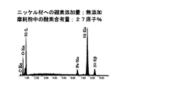
- the composition of the wear powder obtained in the test using a nickel cold-rolled coil containing no boron for forming the disk was analyzed by an energy dispersive X-ray spectrometer (SEM-EDX) attached to a scanning electron microscope. As shown in FIG. In this analysis, an oxygen peak was detected in addition to nickel and a small amount of iron, and when quantitative analysis was performed based on this oxygen peak, 27 atomic% oxygen was confirmed.
- the oxygen in the wear powder is considered to exist mainly as nickel oxide [NiO] or nickel hydroxide [Ni (OH) 2 ], but the oxygen content of the compound (excluding hydrogen) is 27 atoms in any chemical formula. More than%. Nevertheless, the reason why the oxygen content of the wear powder in FIG. 1 is 27 atomic% is that the wear powder is not a pure compound, such as nickel oxide, nickel hydroxide, or a mixture thereof, and oxide. This is considered to be because it is a mixture with metallic nickel not forming a compound.
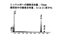
- FIG. 2 shows composition analysis of wear powder when a nickel cold-rolled coil containing 15 ppm boron (determined by an inductively coupled plasma (ICP) emission spectroscopic analyzer) is used as a disk by SEM-EDX analysis. Results are shown.
- ICP inductively coupled plasma
- the form of the wear powder differs depending on the oxygen content in the wear powder.
- individual particles exist independently, whereas In many wear powders, it was confirmed that fine particles aggregated to form coarse particles.
- a similar friction test was performed with a smaller pressing load (1 kgf)
- a disc containing no trace of boron 15 ppm was observed in the disc containing no boron, although generation of wear powder was confirmed. No wear powder could be confirmed.
- the nickel surface is oxidized on the new surface due to friction on the surface of the disk not containing boron, and the oxide aggregates while falling off to form wear powder, whereas it contains boron. This is presumably because the oxidation of nickel was suppressed on the surface of the disk, and abrasion powder was not generated particularly under conditions of a small contact pressure. Also from this, in order to prevent the workability of the cold rolling in the production of the nickel cold rolling coil from being deteriorated, the predetermined boron is contained and the contact between the work roll and the rolled material (nickel coil) It is recognized that keeping the pressure small is important.
- hot rolling was performed at a heating temperature of 1200 ° C. to obtain a hot rolled coil having a thickness of 4 mm.
- the hot-rolled coil was continuously annealed in an atmospheric heat treatment furnace at 820 ° C., and then the scale was removed by shot blasting and nitric hydrofluoric acid washing to obtain a hot-rolled annealed plate.
- a cold rolled test was performed using this hot-rolled annealed plate. However, in order to increase the coil length except for some tests, the coil was cold rolled from a thickness of 0.2 mm to 0.8 mm. Was subjected to continuous bright annealing in an AX gas atmosphere at 820 ° C. to obtain an evaluation coil.
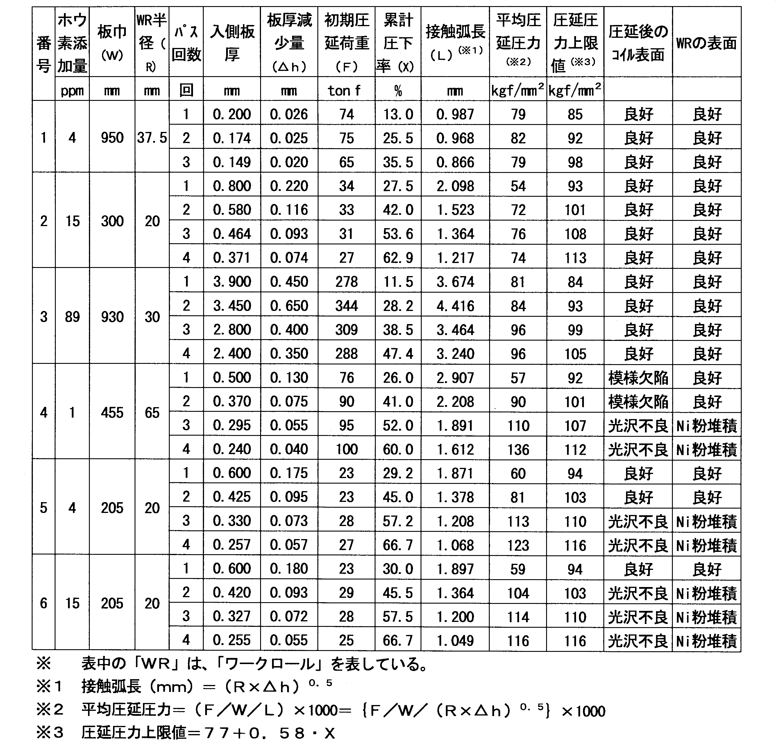
- This hot-rolled annealed plate (or the above-described evaluation coil) was subjected to 3-pass or 4-pass cold rolling under the conditions shown in Table 7 below to produce a nickel cold-rolled coil.
- Table 7 shows the results of visual observation of the surface state of the nickel cold-rolled coil and the surface of the work roll (WR) after each pass.
- the average rolling is obtained by dividing the rolling load ("initial rolling load" in the table: F) by the sheet width (W) and the contact arc length (L) obtained by the above calculation (F / W / L). The pressure was determined.
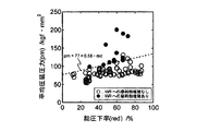
- FIG. 3 shows a graph of data collected based on the actual rolling results.
- those indicated by black circles indicate that the accumulation of rolling wear powder on the work roll was observed when cold rolling was performed under those conditions, and those indicated by white circles. Indicates that no accumulation of rolling wear powder on the work roll was observed when cold rolling was performed under these conditions.
- the average rolling pressure (kgf / mm 2 ) is set to 77 + 0.58X (where X is the value of the cumulative rolling reduction by the pass, and the unit is “%”). It turns out that the fall of workability
- the nickel cold rolled coil of the present invention can suppress problems caused by rolling wear powder in the cold rolling process. From the above results, it can also be seen that in the method for producing a nickel cold rolled coil according to the present invention, problems due to rolling wear powder can be suppressed, so that high productivity and yield can be expected.
- the metal surface is covered with an oxide film, that is, a metal oxide.
- the surface of the nickel thin plate is considered to be covered with nickel oxide [NiO].
- the white powder (a) collected in the slit cutting process shows a clear peak at the position of the hydroxide [Ni (OH) 2 ], and the surface of the conventional nickel thin plate (b) The film also exhibits a hydroxide peak. From this fact, the white powder is the one in which the surface film of the nickel thin plate has fallen off, and this surface film is formed by the oxide [NiO] absorbing moisture in the atmosphere and the hydroxide [Ni (OH 2 ) It is thought that it changed to 2 ].
- Nickel oxide (NaCl type structure) and hydroxide (CdI2 type structure) are structurally different, and the latter is considered to be weak against shearing stress because of the layered structure. That is, it is considered that the presence of nickel hydroxide in the surface film makes the film brittle, and thus the amount of white powder generated increases. In order to solve the above problem, it is considered that if nickel oxidation can be suppressed, the amount of nickel hydroxide in the surface film decreases, and the amount of white powder generated in the slit cutting process can be reduced.
- Elements that have a lower oxidation potential than nickel and can be added in a small amount to nickel include boron, silicon, aluminum, titanium, manganese, magnesium, and calcium.
- boron is particularly effective because of its high diffusion rate in the metal.
- Nickel oxide can be suppressed and the thickness of the oxide film is reduced, and the surface film is less likely to become brittle due to the oxide being changed to a hydroxide.
- FIG. 4C boron-containing nickel thin plate
- a strong peak is shown at the position of metallic nickel, and the hydroxide peak as in the conventional product (b) is hardly observed.
- a clear peak is recognized in the boron region as shown in FIG. That is, it can be seen that the outermost surface of the nickel thin plate is in a state where boron is concentrated, and the formation of nickel oxide is suppressed.
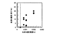
- FIG. 6 shows the relationship between the boron addition amount and the surface boron concentration.
- the data indicated by the black triangle legend is for the outermost surface boron concentration of less than 1 atomic%, and the data indicated by the black circle legend is for the outermost surface boron concentration of 1 atomic% or more.
- the surface boron concentration increases as the boron addition amount increases.
- FIG. 7 shows a graph plotting the relationship between the surface boron concentration and the nickel oxide ratio.
- the data indicated by the black triangle legend is for the outermost surface boron concentration of less than 1 atomic%, and the data indicated by the black circle legend is for the outermost surface boron concentration of 1 atomic% or more. From this figure, it can be seen that the nickel oxide ratio tends to decrease as the surface boron concentration increases. That is, it can be confirmed that the oxidation of nickel is suppressed by the surface concentration of boron.
- Sample No. with a boron addition amount of 0.0004 mass% The 12 to 16 nickel thin plates are designated as sample nos. There was a problem in that it was necessary to increase the bonding load in order to obtain the same bondability as that of the 1 to 11 nickel thin plate.
- the nickel material of the present invention is excellent in surface properties. As described above, according to the present invention, it can be seen that a nickel material with few defects such as cracks and wrinkles can be produced efficiently.
Landscapes
- Chemical & Material Sciences (AREA)
- Engineering & Computer Science (AREA)
- Materials Engineering (AREA)
- Mechanical Engineering (AREA)
- Metallurgy (AREA)
- Organic Chemistry (AREA)
- Physics & Mathematics (AREA)
- Thermal Sciences (AREA)
- Crystallography & Structural Chemistry (AREA)
- Metal Rolling (AREA)
Abstract
Description
例えば、ニッケルを99重量%以上含有するニッケル材は、導電性、機械的強度、耐食性などに優れることから、電池の内部配線材料(リード、タブ)や耐アルカリ用プラント材料などに広く使用されている。
このような部材の形成に用いられるニッケルは、鉄やアルミニウムなどの一般的な金属に比べて高価であるため、ニッケル材の製造時には、欠陥の発生を抑制し、原材料の消費量を削減させることが重要な課題となっている。
これらの欠陥を抑制する方法としては、熱間圧延前の連続鋳造スラブの表面に酸化防止剤を塗布し、特定温度で加熱保持した後、熱間圧延を行う方法が知られている(特許文献1参照)。
このような欠陥を抑制する方法としては、従来、原材料中の硫黄成分の含有量を0.001%以下とする方法が採用されている。
この中間温度脆性は、ニッケル材を製造する際の鋳造工程や圧延加工前の加熱工程において発生する熱による歪や、ニッケル材を低速度で引き伸ばす等した際の歪によって、結晶粒界の延性(粒界延性)が低下されて出現することが知られている。
このため鋳造品を製造した場合や熱間圧延前のニッケル材を加熱した場合、脆化が起こってニッケル材の内部や表面の割れ等の原因となるおそれがある。
また、中間温度脆性は、硫黄成分に起因する脆化でもないため、硫黄成分の含有量を制御することでも抑制することは難しい。
このスローヒートとは、熱間圧延前のニッケル材を昇温速度が低速となるように低い温度から加熱する方法のことであり、このことによって熱歪の発生を低減し、結晶粒界の脆化を抑制するものである。
しかしながら、スローヒートを行った場合であっても、熱歪の発生を完全に抑制することはできず、中間温度脆性を完全に防止させることは難しい。
更に、スローヒートを行った場合には、圧延加工を行うのに十分な温度となるまでに多大な時間が必要となってしまうためニッケル材の生産性が大変悪いものとなる。
具体的には、前記ニッケル材は、質量で99%以上のニッケルと3ppm以上110ppm以下のホウ素と含有する原材料から製造されたものである。
更に、前記ニッケル材は、原材料としてニッケル及びホウ素以外に不純物を含有している。
該不純物は、本発明の効果に影響を与えないように、その総量が0.5質量%以下となるように調製されることが好ましい。
これら不可避不純物の含有量は、その総量が0.5質量%以下となるように調整されている場合であっても、各成分は下記のような含有量であることが好ましい。
すなわち、炭素は、質量で0.02%以下であり、通常0.01%程度とされる。
また、ケイ素は、0.35%以下であり、通常0.03%程度とされ、マンガンは、0.35%以下であり、通常0.2%程度とされる。
また、リンは、0.01%以下であり、通常、0.002%程度とされ、イオウは、0.01%以下であり、通常、0.001%程度とされる。
また、銅は、0.25%以下であり、通常、0.02%程度とされ、マグネシウムは、0.1%以下であり、通常、0.01%程度とされる。
さらに、鉄は、0.4%以下であり、通常、0.1%程度とされ、酸素は0.005%以下であり、通常、0.003%程度とされる。
さらには、ニッケル材の廃材(スクラップ材)を原材料として利用した際に、このスクラップ材によって混入される不純物も本実施形態のニッケル材に適宜含有され得る。
具体的には、前記ニッケル材は、原材料としてホウ素を含有することにより、その製造工程において、所定温度で結晶に低速度で歪が加わった場合であっても中間温度脆性の出現が抑制されることからこの中間温度脆性に起因する割れや表面疵等の欠陥が発生するのを抑制することができる。
結晶に加わる低速度の歪の原因としては、鋳造工程や圧延前の加熱工程において生じる熱歪やニッケル材を低速度で引き伸ばしたりした際に生じる歪等が考えられる。
このため、ニッケル材を製造するのに際して用いる原材料にホウ素を3ppm以上、110ppm以下含有添加することが重要である。
すなわち、ニッケル材中でホウ素は、結晶粒界に偏析した状態で存在するため、結晶に低速度で歪が加わった場合であっても、転位の影響が結晶粒界に集中することを抑制させることが出来、粒界部の延性の低下を抑制することができる。
よって、中間温度脆性が抑制され、それに起因する割れ等の欠陥が製造時に発生することを抑制することができる。
例えば、質量で99%以上のニッケルと、3ppm以上110ppm以下のホウ素とが含有されているスラブを鍛造にて作製する際や、該スラブを圧延する際に割れが発生するおそれを低減でき効率良くニッケル材を製造することができる。
例えば、ニッケル材は、汎用性の高い板状の形態で供給されることが多く、その工業生産にあたっては連続的に製造することができ生産性に優れることからコイル状に冷間圧延する方法が適している。
しかし、ニッケルは軟質な金属であるうえワークロールに凝着し易いため、圧延中にニッケルコイルの表面が摩耗されて圧延摩耗粉(以下、単に「摩耗粉」ともいう)を発生し易く、この摩耗粉によって表面に傷を発生させる場合がある。
そして、ホウ素は、この摩耗粉の発生を抑制させるのに有効な成分である。
まず、摩耗粉の影響に関して説明する。
摩耗粉の影響は、その性質によって主として以下の2種類に大別することができる。
第一の影響は、摩耗粉の凝集性が高い場合に、圧延中のワークロールのロールバイト内に摩耗粉の凝集塊が形成され、この凝集された摩耗粉が圧延中のニッケル材の表面に転写されて起こる製品の外観不良である。
第二の影響は、圧延摩耗粉がワークロール表面に付着して堆積する性質を持つ場合に、堆積した摩耗粉によってワークロールの表面が粗面化して表面光沢が低下する他、摩擦係数の急激な増大が発生し、圧延荷重が増大してコイル長手方向での板厚変動を生じたり、圧延荷重超過によって圧延不能に陥ったりすることが挙げられる。
あるいは、摩耗粉の堆積したワークロールを圧延機から取り出して未使用のワークロールに交換する作業を頻繁に行う方法がその対策として挙げられる。
しかしながら、いずれにしても大幅な生産性の低下を余儀なくされる。
例えば、ホウ素を含有しない場合には、圧延によって露出した新生表面や凝着摩耗で脱落したニッケル微粒子がワークロールバイト内の高温高圧環境下において酸化されやすく、この酸化されたニッケル微粒子は、凝集性を待つために粗大な摩耗粉を形成し、ワークロールバイト内に偏在して模様欠陥を発生させるおそれを有する。
特に接触圧力の小さな圧延条件においては摩耗粉の発生がほとんど無く、模様欠陥が発生するおそれを低減させうる。
また、水酸化物の形成も抑制され、ニッケル水酸化物の脱落も防止されうる。
すなわち、製造される冷間圧延コイル(ニッケル材)においては、圧延摩耗粉によって生じる問題が抑制され得る。
また、摩耗粉によるトラブルを回避するために冷間圧延コイルを製造することができる。
したがって、冷間圧延する長さに制限を設けたり、ワークロールを頻繁に取り替えたりすることなく良好なる品質のニッケル材を製造することができる。
一方で、上限値(100ppm)は、この値を超えると粗大なホウ化物(ボライド)を形成して加工性や耐食性の劣化を招いてしまうおそれを有することから設定されたものである。
一方で、上記のように熱間圧延コイルにホウ素が含有されている場合には、熱間圧延コイルの表面には、通常、ホウ素が濃化されていることから、この熱間圧延コイルを冷間圧延する場合に、新生表面等においてこのホウ素が優先酸化されてニッケル酸化物の形成を抑制させる。
また、このようにホウ素を含有させることで、例えば、焼鈍などための熱処理をニッケルコイルに施した際に、ニッケルコイル表面でニッケルよりもホウ素が優先的に酸化されて酸化ホウ素(B2O3)や窒化ホウ素(BN)を形成する。
しかも、前者(B2O3)は、450℃程度で溶解してニッケルコイルの表面を覆う作用を有することから、ニッケル酸化物の形成がより一層抑制されることとなる。
この場合にも、このニッケル微粒子が、圧延バイト内でワークロール表面に凝着堆積して、結果的に圧延荷重の増大を招くおそれがある。
例えば、熱間圧延後に、この熱間圧延コイルに対して冷間圧延を1パス実施してニッケル冷間圧延コイルを作製する場合に熱間圧延コイルの板厚をT0(mm)、冷間圧延後の板厚をT1(mm)とすると、この1パスにおける累計圧下率:X1(%)は、(T0-T1)/T0×100(%)となる。
P1≦77+0.58・X1・・・(1)
上記式(1)を満足させるように冷間圧延を実施することが好ましい。
そして、第二パスにおける平均圧延圧力の値をP2(kgf/mm2)、第三パスにおける平均圧延圧力の値をP3(kgf/mm2)とすると、下記式(2)、(3)をそれぞれ満足させるように第二パス及び第三パスの冷間圧延を実施することが好ましい。
P2≦77+0.58・X2・・・(2)
P3≦77+0.58・X3・・・(3)
その他の方法としては、圧延張力を増大する方法や、小径ワークロールを使用する方法などが挙げられる。
また、ワークロールバイト内の油膜厚みを増大して圧延摩擦係数を減少させるために高粘度圧延油を用いたり圧延速度を増大させたりすることも有効である。
平均圧延圧力を制限するこれらの方法は、上記に限定されず種々の方法を採用することができ、しかも、これらの方法を複数組み合わせて実施することもできる。
このようなことから、形成されるニッケル冷間圧延コイルの長さ方向中央部の80%程度において上記式(1)等の関係が満足されていれば、通常、圧延摩耗粉の堆積に伴う問題の発生が抑制されうる。
例えば、スリット切断においては、板押さえ部品と金属薄板とが摺接されることから、金属薄板の表面に擦過疵が形成されることを防止すべく、板押さえ部品は、金属薄板に接する接触面がフェルト等の繊維部材で形成されたりしている。
しかし、ニッケル薄板などをスリット切断する場合においては、上記板押え部品とニッケル薄板との接触箇所からニッケル水酸化物による粉末が発生しスリット後のニッケル薄板の表面に微細な疵を生じさせてしまうことがある。
なお、より確実にニッケル水酸化物の形成を防止させるためには、ニッケル材の最表面におけるホウ素の濃度を1原子%以上とさせることが好ましい。
より好ましくは最表面におけるホウ素の濃度を3原子%以上となるようにホウ素の表面濃化を実施させることが望ましい。
例えば、熱処理には、窒素、水素、アルゴンの内の1種、又は複数種を混合した混合ガスを雰囲気ガスとして用い、しかも、露点が-30℃以下、好ましくは、-40℃以下、特に好ましくは-70℃以下の雰囲気ガスを用いて、この雰囲気ガス中でニッケル材を以上900℃以下の範囲の内のいずれかの温度に加熱することでホウ素の表面濃化をより好適に実施させ得る。
一方で、上記のような上限値(900℃)が設定されているのは、この温度を超える温度とするとホウ素の酸化物の昇華が顕著になって、ニッケル材の表面酸化被膜の形成を十分に抑制させることができなくなるおそれを有するためである。
したがって、少なくとも、表面におけるホウ素の濃度が1原子%以上、好ましくは、3原子%以上となるように熱処理条件を定めることが好ましい。
なお、最表面におけるホウ素の濃度の上限は、特に限定されるものではないが最大に濃化させたとしても、通常、20原子%程度となる。
このようなホウ素の表面濃化をさせるためには、99.0質量%以上のニッケルを含有するニッケル材にさらに4ppmを超えるホウ素を含有させる方法が挙げられる。
より確実に、ホウ素の表面濃化をさせるためには、ホウ素含有量を6ppm以上とすることが好ましく、8ppm以上とすることがさらに好ましい。
また、このようなリード材以外に用いられるような場合にあっては、パンチング加工される可能性もある。
従来のニッケル薄板では、繰返してパンチング加工するうちに表面の酸化皮膜が剥がれて金型に付着し、クリアランス量を変化させて、切断バリを端面部に発生させたり、場合によっては製品形状が大きく損なわれたり、押し込み疵等が発生したりするおそれを有していた。
しかし、上記のようにして得られるニッケル薄板は、ホウ素の作用によって強度の高い安定した表面皮膜を有していることから、長期にわたって安定した状態でパンチング加工を実施することができ、得られる製品の品質に対しても有益な効果を期待することができる。
(試験体の作製)
1.鋳塊の作製
ニッケル以外の成分構成が下記表1に記載の成分構成となるように、高周波真空溶解によって100kgの鋳塊を作製し、比較例1及び2、実施例1~4とした。

上記各鋳塊を1200℃で熱間鍛造し、厚さ:20mmの鍛造スラブを作製した。そして、該鍛造スラブから直径:10mm、長さ:110mmの丸棒型の引張試験片を各比較例及び実施例毎に作製した。なお、熱間鍛造時の温度条件としては、各試験片間で同一となるように作製した。
3.熱歪評価試験片の作製
上記各鋳塊から100mm角の立方体を切り出し、表面に酸化防止剤を塗布して各比較例及び実施例毎に熱歪評価試験片を作製した。
1.試験方法
上記各引張試験片を1分間で下記表2に記載の温度となるように昇温加熱し、その後60秒間保持した。
そして、加熱した各引張試験片を用いて引張試験を行った。各引張試験片を引っ張る際の条件としては、下記表2に記載の歪速度(引張速度)で試験を行った。
2.評価方法
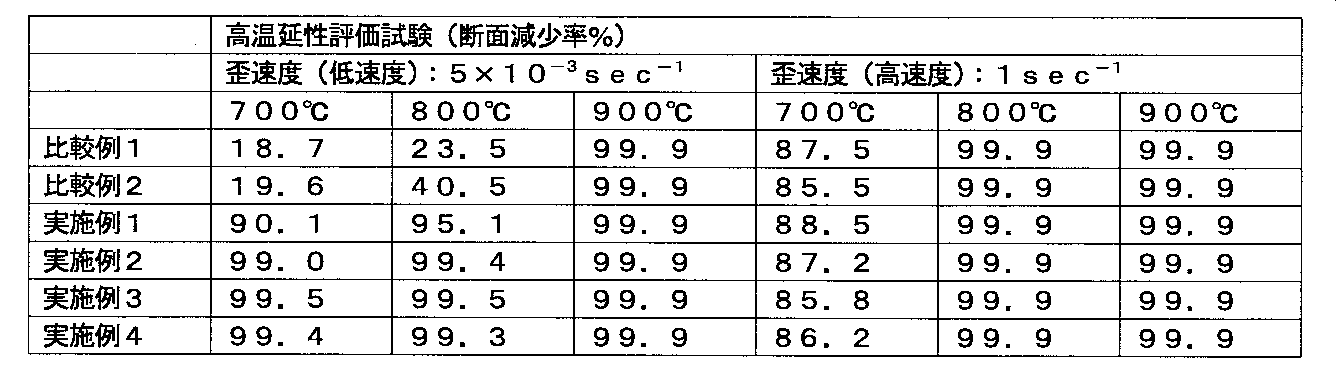
断面減少率(引張試験前の試験体の断面積に対する引張試験後の試験体の断面積減少量の割合)を測定し、粒界延性の評価を行った。試験結果は、下記表2に示す。
1.試験方法
常温の上記各熱歪評価試験片を、1250℃に加熱された加熱炉内に配置し、各試験片が1250℃となるまで急速加熱試験を行った。また、常温の各熱歪評価試験片を所定の昇熱速度(10℃/min)で加熱し、各試験片が1250℃となるまで徐加熱試験を行った。
2.評価方法
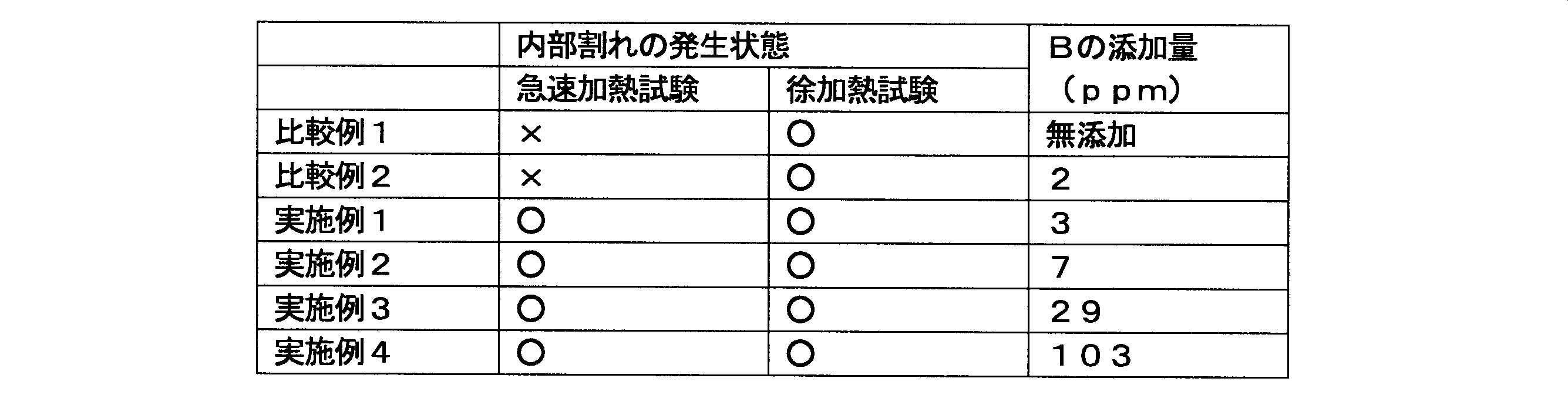
加熱後(1250℃)の各熱歪評価試験片をプレスハンマー設備にて鍛造し、30mm厚の鍛造材を作製した。そして、該鍛造材の30mm厚断面のカラーチェック(液体浸透試験)を行って内部割れの発生状態を評価した。試験結果は、内部割れが発生したものを「×」、発生しなかったものを「○」として下記表3に示す。
1.試験体の作製
下記表4に記載の成分構成となるように、30トンの電気炉及び連続鋳造プロセスで150mm厚×1000mm幅のCCスラブを鋳造し、比較例3、実施例5及び6とした。

(1)内部割れ評価
上記CCスラブの150mm厚断面のカラーチェック(液体浸透試験)を行い、内部割れの発生状態の評価を行った。試験結果は、内部割れが発生したものを「×」、発生しなかったものを「○」として下記表5に示す。
上記CCスラブを1250℃の炉内に2時間30分配置して加熱した後、熱間圧延して30mm厚の熱延板を作製した。そして、30mm厚断面のカラーチェックを行い、内部割れの発生状態の評価を行った。試験結果は、内部割れが発生したものを「×」、発生しなかったものを「○」として下記表5に示す。また、ホットコイル(熱間圧延したCCスラブをコイル状に巻きまわした状態)で表面疵の評価を行った。試験結果は、下記表5に示す。なお、表面疵の試験結果としては、熱延板を一方向に1m間隔で区分した際の全体の区分数に対する表面疵が発生した区分数の割合を示す。
(3)冷間圧延試験
上記ホットコイルを巻き解き、常温において冷間圧延して0.1mm厚の冷延板を作製し、フクレ疵の評価を行った。試験結果は、下記表5に示す。なお、フクレ疵の試験結果としては、熱延板を一方向に1m間隔で区分した際の全体の区分数に対するフクレ疵が発生した区分数の割合を示す。

(1)高温延性評価試験について
実施例1~4と比較例1及び2とを比較すると、歪速度が高速度である場合には、実施例1~4と比較例1及び2との両方が、全ての温度域において85%以上の断面減少率となっており、ホウ素の添加による影響は確認されなかった。これは、歪速度が高速度である場合、断面減少率は硫黄成分の量に影響されるため、実施例及び比較例の硫黄成分を10ppm以下の微量にしたことにより、高い断面減少率を示したと考えられる。
一方、歪速度が低速度である場合には、700℃及び800℃の加熱温度において、比較例1及び2の断面減少率が実施例1~4の断面減少率よりも著しく低い値であることが認められる。これは、中間温度脆性の影響により、比較例1及び2の試験体の粒界部の延性が低下し、試験体が脆くなったため、断面減少率が低下したと考えられる。
これに対し、実施例1~4は、全ての温度域において、低速度の歪が結晶に加わった場合であっても、断面減少率が90%以上と高くなっている。これは、700℃~900℃の温度で低速度の歪が加わったニッケル材であっても、中間温度脆性を示さなかったためと考えられる。
実施例1~4と比較例1及び2とを比較すると、徐加熱を行った場合には、実施例1~4と比較例1及び2との両方に内部割れは発生しておらず、ホウ素の添加による影響は確認されなかった。これは、徐加熱することによって熱歪の発生が抑制されたためと考えられる。
一方、急速加熱を行った場合には、比較例1及び2に内部割れが確認されたのに対し、実施例1~4には内部割れは確認されなかった。これは、急速加熱することによって発生する熱歪(低速度で生じる歪)がニッケル材に加わり、比較例1及び2の試験体では中間温度脆性を示したため、結晶粒界部が脆化し、内部割れを引き起こしたと考えられる。これに対し、実施例1~4の試験体では熱歪が加わった状態であっても中間温度脆性を示さなかったため、内部割れが発生しなかったと考えられる。
実施例5及び6と比較例3とを比較すると、比較例3では、CCスラブ及び熱延板で内部割れが発生しているのに対し、実施例5及び6では、内部割れは発生していないことが認められる。また、比較例3では、ホットコイルの表面疵や冷延板のフクレ疵が発生しているのに対し、実施例5及び6では、表面疵やフクレ疵が略発生していないことが認められる。
これは、CCスラブを作製する際の熱歪によって比較例3の試験体が中間温度脆性を示したため、粒界部の延性が低下し、内部割れ等の欠陥が発生したと考えられる。これに対し、実施例5及び6の試験体では、CCスラブを作製する際の熱歪が結晶に加わった状態であっても中間温度脆性を示さなかったため、内部割れ等の欠陥が発生しなかったと考えられる。
次いで、ホウ素の含有による摩耗粉の抑制効果について評価した。
まず、冷間圧延における摩耗粉の性質を調査するためにピンオンディスク法による摩擦試験を行った。
ピンオンディスク法は摩擦面での摩耗量評価に適した汎用の摩擦試験法であり、柱状のピンの端面を円板状のディスク表面に押し付けて回転すべりさせる試験法である。
今回の評価試験では、実際のワークロール(SKD11相当)から切り出した8.8mm角の断面形状を有する長さ30mmの四角柱のピンを用いた。
また、ディスクには実機製造した厚さ約1mmの2種類のニッケル冷間圧延コイル(焼鈍品)から切り出した直径80mmの円板を使用した。
このディスクに含有されるニッケル以外の主な成分は、下記表6に示すとおりである。

なお、この試験は、摩耗粉の発生を促進させるために無潤滑条件で行った。
この分析においては、ニッケルと微量の鉄以外に酸素のピークが検出され、この酸素ピークを基に定量分析したところ、27原子%の酸素が確認された。摩耗粉中の酸素は、主に酸化ニッケル[NiO]もしくは水酸化ニッケル[Ni(OH)2]として存在すると考えられるが、いずれの化学式においても化合物の酸素含有量(水素を除く)は27原子%より多くなる。
それにもかかわらず図1における摩耗粉の酸素含有量が27原子%となった原因は、摩耗粉が純粋な化合物では無く、酸化ニッケル、又は水酸化ニッケル、又はこれらの混合物と、酸化物等の化合物を形成していない金属ニッケルとの混合物であるためであると考えられる。
この図2からもわかるように、ホウ素を含有するニッケル冷間圧延コイルをディスクに用いた摩擦試験において発生する摩耗粉は、殆どニッケルのみのピークしか確認できず、微量の酸素ピークを基に定量分析したところ、5(±3)原子%の酸素が確認されるにとどまった。
このことからもホウ素がニッケルの酸化物を抑制することがわかる。
また、同様の摩擦試験を、より小さな押し付け荷重(1kgf)で実施したところ、ホウ素の含有されていないディスクにおいては、摩耗粉の発生が確認されるものの、微量のホウ素(15ppm)を含有するディスクは、摩耗粉が確認できなかった。
このことからも、ニッケル冷間圧延コイルの製造における冷間圧延の作業性の低下を防止するためには、所定のホウ素を含有させるとともに、ワークロールと圧延材(ニッケルコイル)との間の接触圧力を小さく保つことが重要であると認められる。
実機電気炉での溶解工程と真空下酸素吹精脱炭法(VOD)での精錬工程を経てホウ素含有量の異なる材料を溶製し、連続鋳造法によって厚さ150mmで幅が1000mmのスラブを作製した。
このとき、VODでの精錬工程において、得られるスラブのホウ素の含有量が4ppm及び15ppm、及び89ppmとなるようにフェロボロン(鉄とホウ素の合金)の添加を実施した。
また、フェロボロンを加えることなく、ホウ素が1ppmしか含有されていないスラブも併せて作製した。
スラブ表面に存在する割れなどの欠陥を切削除去した後、加熱温度1200℃で熱間圧延し厚さ4mmの熱延コイルを得た。
この熱延コイルを820℃の大気熱処理炉で連続焼鈍した後にショットブラストおよび硝弗酸酸洗によってスケールを除去し熱間圧延焼鈍板を得た。
この熱間圧延焼鈍板を用いて冷間圧延テストを行ったが、一部の試験を除いてはコイル長さを長くするために、厚さ0.2mmから0.8mmまで冷間圧延したコイルを820℃のAXガス雰囲気中で連続的に光輝焼鈍して評価用コイルとした。
各パス後のニッケル冷間圧延コイルの表面状態とワークロール(WR)の表面を目視観察した結果を表7に示す。
また、ワークロールの半径(表中の“WR半径”:R)と、板厚減少量(△h)とによって接触弧長(L=(R×△h)0.5)を計算によって求めるとともに、圧延荷重(表中の“初期圧延荷重”:F)を、板巾(W)と、上記計算により求めた接触弧長(L)とで除算(F/W/L)することによって平均圧延圧力を求めた。
番号1から3に示したニッケル冷間圧延コイル製造条件においては、ワークロールの表面に圧延摩耗粉の堆積は見られず、この圧延摩耗粉を原因としたニッケル冷間圧延コイルの模様欠陥や光沢不良といった問題も観察されなかった。
一方で、ホウ素含有量が、4ppm未満である番号4の事例においては、ホウ素の含有量が十分ではないことから、凝集した圧延摩耗粉の転写による表面の模様欠陥が見られた。
また、後段側のパスでは、圧延圧力上限値を超える平均圧延圧力となったためにワークロール表面にニッケル粉の堆積が認められ、ニッケル冷間圧延コイルの表面の光沢度を低下させる結果となった。
しかも、圧延の進行に伴って急激な圧延荷重の増大が見られた。
また、番号5と6の事例では、圧延圧力上限値を超える平均圧延圧力となった際において、ワークロール表面にニッケル粉の堆積が認められ、ニッケル冷間圧延コイルの表面の光沢度を低下させる結果が見られた。
このことから、所定量のホウ素を含有させることとともに、平均圧延圧力(kgf/mm2)の値を所定の値以下とすることで冷間圧延における作業性の低下をより確実に防止し得ることが確認された。
この図3のグラフの凡例の内、黒丸で示すものは、その条件で冷間圧延を実施した場合にワークロールへの圧延摩耗粉の堆積が見られたことを示しており、白丸で示すものは、その条件で冷間圧延を実施した場合にワークロールへの圧延摩耗粉の堆積が見られなかったことを表している。
また、破線は、累計圧下率(総圧下率)を変数「red」、平均圧延圧力を変数「pm」とした場合に、「pm=77+0.58red」の関数で表される直線を示している。
このことからも、平均圧延圧力(kgf/mm2)の値を77+0.58X(なお、Xは、そのパスによる累計圧下率の値で、単位は“%”である)以下とすることによって冷間圧延における作業性の低下をより確実に防止し得ることがわかる。
また、上記の結果からは、本発明のニッケル冷間圧延コイルの製造方法においては、圧延摩耗粉による問題を抑制し得ることから高い生産性と歩留まりとが期待されうることもわかる。
(ホウ素添加の効果について)
従来のニッケル薄板をスリット切断した際に発生された白色粉末を採取し、これをESCA分析した。
また、同じくESCAにて従来のニッケル薄板の表面と、材料成分としてホウ素を所定量で含有させて作製したニッケル薄板の表面とを分析した結果を、図4、図5に示す。
図中の(a)は白色粉末、(b)は従来のニッケル薄板、(c)はホウ素を含有させたニッケル薄板の分析結果である。
ニッケル薄板についても同様に、その表面はニッケル酸化物[NiO]で覆われていると考えられる。
図4のESCA分析結果では、スリット切断工程で採取した白色粉末(a)は水酸化物[Ni(OH)2]の位置に明瞭なピークを示しており、従来のニッケル薄板(b)の表面皮膜も同様に水酸化物のピークを呈している。
このことから白色粉末がニッケル薄板の表面皮膜が脱落したものであること、ならびに、この表面被膜は、酸化物[NiO]が大気中の水分を吸収して経時的に水酸化物[Ni(OH)2]に変化したものと考えられる。
上記の問題解決にはニッケル酸化を抑制できれば表面皮膜中のニッケル水酸化物量は少なくなり、スリット切断工程での白色粉末の発生量を少なくできると考えられる。
中でもホウ素は、金属中での拡散速度が速く特に有効である。
その結果、ニッケル酸化物の形成を抑制できるとともに酸化皮膜の厚みも薄くなり、この酸化物が水酸化物に変化することによる表面皮膜の脆化も生じにくくなる。
さらに、この(c)では、図5に示すようにホウ素の領域に明瞭なピークが認められる。
すなわち当該ニッケル薄板の最表面は、ホウ素が濃化した状態となっており、ニッケル酸化物の生成が抑制されていることがわかる。
表8に示す、サンプルNo.1~16のニッケル薄板を作製し評価を行った。
まず、主成分であるニッケルを、電気炉を用いた真空下酸素吹精脱炭法(VOD)プロセスにより溶製し、この溶製過程でホウ素を表1に示す量(B添加量)となるように添加した。
得られたスラブを熱間圧延し、その後、最終板厚が表8の値(板厚)となるまで冷間圧延しニッケル薄板を作製した。
得られたニッケル材は光輝焼鈍炉にて熱処理を行った。このときの焼鈍炉の雰囲気ガス組成、露点および熱処理温度は、表8の通りとした。
各サンプルNo.のニッケル薄板の表面皮膜の組成を調べるためにESCA分析を行い、ニッケルとホウ素の存在量を調査した。
ニッケル領域については、ピーク解析を行い酸化物と金属の状態比率を調べた。
この場合、ニッケルの酸化物比率が低いほど表面酸化皮膜が薄いことを示している。
結果を、表8に示す。
いずれも、添加量に比べて極めて高濃度な状態で表面にホウ素が存在しており、ホウ素が表面に濃化していることがわかる。
この図からも明らかなように、ホウ素添加量を多くするほど表面ホウ素濃度も増加している。
この図からは、表面ホウ素濃度が高くなるほどニッケル酸化物の比率が低下する傾向にあることがわかる。すなわち、ホウ素の表面濃化によってニッケルの酸化が抑制されていることが確認できる。
同じスリット切断装置を用いて、各サンプルNo.のニッケル薄板(200mm幅のコイル)を50mm幅にスリット加工したときに白色粉末の発生を観察し、白色粉末が発生しなかった場合を「○」、発生はしたが少量であった場合を「△」、大量に発生した場合を「×」として判定した。
結果を、表8に示す。
各サンプルNo.のニッケル薄板を、厚み10μmの銅箔に超音波接合し、容易に接合できる場合を「○」、接合性に難がある場合を「△」として判定した。
結果を、表8に示す。

以上のように本発明によれば、割れや疵等の欠陥の少ないニッケル材が効率良く製造されることがわかる。
Claims (7)
- 質量で99%以上のニッケルと、3ppm以上110ppm以下のホウ素とが含有されていること特徴とするニッケル材。
- 前記ホウ素の含有量が4ppm以上100ppm以下である請求項1記載のニッケル材。
- 最表面におけるホウ素の濃度が1原子%以上である請求項1又は2記載のニッケル材。
- 質量で99%以上のニッケルと、3ppm以上110ppm以下のホウ素とが含有されているスラブを作製し、該スラブを圧延して板状のニッケル材を製造することを特徴とするニッケル材の製造方法。
- 質量で99.0%以上のニッケルと4ppm以上100ppm以下のホウ素とを含有する熱間圧延コイルを前記スラブを用いて作製し、該熱間圧延コイルに1回以上の冷間圧延を実施して前記ニッケル材である冷間圧延コイルを製造する請求項4記載のニッケル材の製造方法。
- 前記冷間圧延を、各パスにおける平均圧延圧力(kgf/mm2)の値が、当該パスによる累計圧下率の値をX(%)とした場合に、(77+0.58・X)を超えないようにして実施する請求項5記載のニッケル材の製造方法。
- 窒素、水素、及びアルゴンの内の1種以上が用いられてなり露点が-30℃以下の雰囲気ガス中における450℃以上900℃以下の範囲の内のいずれかの温度での熱処理を前記冷間圧延コイルに実施して最表面のホウ素の濃度が1原子%以上となるように濃化させる請求項5又は6記載のニッケル材の製造方法。
Priority Applications (2)
| Application Number | Priority Date | Filing Date | Title |
|---|---|---|---|
| CN200980148332.1A CN102232122B (zh) | 2008-12-02 | 2009-12-02 | 镍材及镍材的制造方法 |
| KR1020117013479A KR101311558B1 (ko) | 2008-12-02 | 2009-12-02 | 니켈재 및 니켈재의 제조 방법 |
Applications Claiming Priority (8)
| Application Number | Priority Date | Filing Date | Title |
|---|---|---|---|
| JP2008-307148 | 2008-12-02 | ||
| JP2008-307151 | 2008-12-02 | ||
| JP2008307148A JP5299762B2 (ja) | 2008-12-02 | 2008-12-02 | ニッケル材及びニッケル材の製造方法 |
| JP2008307151A JP5246547B2 (ja) | 2008-12-02 | 2008-12-02 | ニッケル冷間圧延コイル、及びニッケル冷間圧延コイルの製造方法 |
| JP2009-092984 | 2009-04-07 | ||
| JP2009092984 | 2009-04-07 | ||
| JP2009270250A JP5440931B2 (ja) | 2009-04-07 | 2009-11-27 | ニッケル材料及びその製造方法 |
| JP2009-270250 | 2009-11-27 |
Publications (1)
| Publication Number | Publication Date |
|---|---|
| WO2010064642A1 true WO2010064642A1 (ja) | 2010-06-10 |
Family
ID=42233289
Family Applications (1)
| Application Number | Title | Priority Date | Filing Date |
|---|---|---|---|
| PCT/JP2009/070215 Ceased WO2010064642A1 (ja) | 2008-12-02 | 2009-12-02 | ニッケル材及びニッケル材の製造方法 |
Country Status (1)
| Country | Link |
|---|---|
| WO (1) | WO2010064642A1 (ja) |
Cited By (3)
| Publication number | Priority date | Publication date | Assignee | Title |
|---|---|---|---|---|
| CN115362580A (zh) * | 2020-03-31 | 2022-11-18 | 日铁化学材料株式会社 | 镍氢二次电池集电体用镀Ni钢箔、镍氢二次电池集电体、以及镍氢二次电池 |
| JP7448799B2 (ja) | 2020-04-07 | 2024-03-13 | 日本製鉄株式会社 | ニッケル材およびその製造方法 |
| CN117965940A (zh) * | 2023-12-28 | 2024-05-03 | 深圳市中金岭南鑫越新材料有限公司 | 一种复合金属多孔体及其制备方法 |
Citations (6)
| Publication number | Priority date | Publication date | Assignee | Title |
|---|---|---|---|---|
| JPS61157699A (ja) * | 1984-12-29 | 1986-07-17 | Mitsubishi Metal Corp | 電気めつき用ニツケル陽極材 |
| JPS6372845A (ja) * | 1986-09-12 | 1988-04-02 | Daido Steel Co Ltd | 熱間加工性を改善した高純度Ni |
| JPH02247366A (ja) * | 1989-03-20 | 1990-10-03 | Mitsubishi Metal Corp | B含有Ni基耐熱合金の塑性加工方法 |
| JPH0364436A (ja) * | 1989-08-01 | 1991-03-19 | Daido Steel Co Ltd | 高純度Ni材の製造方法 |
| JPH04229510A (ja) * | 1990-05-24 | 1992-08-19 | General Atomic Co | ニッケルを基材とする、セラミック超伝導体用の基板 |
| JP2006057186A (ja) * | 2005-09-09 | 2006-03-02 | Hitachi Metals Ltd | ハンダ付け性に優れたニッケル材料帯の製造方法 |
-
2009
- 2009-12-02 WO PCT/JP2009/070215 patent/WO2010064642A1/ja not_active Ceased
Patent Citations (6)
| Publication number | Priority date | Publication date | Assignee | Title |
|---|---|---|---|---|
| JPS61157699A (ja) * | 1984-12-29 | 1986-07-17 | Mitsubishi Metal Corp | 電気めつき用ニツケル陽極材 |
| JPS6372845A (ja) * | 1986-09-12 | 1988-04-02 | Daido Steel Co Ltd | 熱間加工性を改善した高純度Ni |
| JPH02247366A (ja) * | 1989-03-20 | 1990-10-03 | Mitsubishi Metal Corp | B含有Ni基耐熱合金の塑性加工方法 |
| JPH0364436A (ja) * | 1989-08-01 | 1991-03-19 | Daido Steel Co Ltd | 高純度Ni材の製造方法 |
| JPH04229510A (ja) * | 1990-05-24 | 1992-08-19 | General Atomic Co | ニッケルを基材とする、セラミック超伝導体用の基板 |
| JP2006057186A (ja) * | 2005-09-09 | 2006-03-02 | Hitachi Metals Ltd | ハンダ付け性に優れたニッケル材料帯の製造方法 |
Cited By (3)
| Publication number | Priority date | Publication date | Assignee | Title |
|---|---|---|---|---|
| CN115362580A (zh) * | 2020-03-31 | 2022-11-18 | 日铁化学材料株式会社 | 镍氢二次电池集电体用镀Ni钢箔、镍氢二次电池集电体、以及镍氢二次电池 |
| JP7448799B2 (ja) | 2020-04-07 | 2024-03-13 | 日本製鉄株式会社 | ニッケル材およびその製造方法 |
| CN117965940A (zh) * | 2023-12-28 | 2024-05-03 | 深圳市中金岭南鑫越新材料有限公司 | 一种复合金属多孔体及其制备方法 |
Similar Documents
| Publication | Publication Date | Title |
|---|---|---|
| JP5880811B2 (ja) | マグネシウム合金鋳造材、マグネシウム合金鋳造コイル材、マグネシウム合金展伸材、マグネシウム合金接合材、マグネシウム合金鋳造材の製造方法、マグネシウム合金展伸材の製造方法、及びマグネシウム合金部材の製造方法 | |
| EP2762585B1 (en) | High-strength hot-dip galvanized steel sheet with excellent mechanical cutting characteristics, high-strength alloyed hot-dip galvanized steel sheet, and method for producing said sheets | |
| JP3558628B2 (ja) | マグネシウム合金板およびその製造方法 | |
| CN106170576A (zh) | 奥氏体系不锈钢及其制造方法 | |
| EP2765209B1 (en) | Copper alloy wire rod and method for producing same | |
| TWI639714B (zh) | 鋼板 | |
| TWI869608B (zh) | 銅合金、銅合金塑性加工材、電子電氣機器用零件、端子、匯流排、導線框、散熱基板 | |
| JP2017160542A (ja) | マグネシウム合金鋳造材、マグネシウム合金鋳造コイル材、マグネシウム合金展伸材、マグネシウム合金部材、マグネシウム合金接合材、及びマグネシウム合金鋳造材の製造方法 | |
| JP2021037543A (ja) | 金属ストリップ、アモルファス金属ストリップを製造するための方法およびナノ結晶金属ストリップを製造するための方法 | |
| JP5246547B2 (ja) | ニッケル冷間圧延コイル、及びニッケル冷間圧延コイルの製造方法 | |
| WO2010064642A1 (ja) | ニッケル材及びニッケル材の製造方法 | |
| CN107075625B (zh) | 高碳钢板及其制造方法 | |
| CN102232122B (zh) | 镍材及镍材的制造方法 | |
| JP4348827B2 (ja) | 成形性に優れたチタン板の製造方法 | |
| JP7263953B2 (ja) | 銅合金トロリ線 | |
| JP2002003968A (ja) | 成形性に優れたチタン板とその製造方法 | |
| JP5299762B2 (ja) | ニッケル材及びニッケル材の製造方法 | |
| JP7445116B2 (ja) | 厚鋼板 | |
| JP6794585B1 (ja) | 熱間圧延用チタン材の製造方法 | |
| JP6869397B2 (ja) | 銅合金板材およびその製造方法 | |
| JP2004183079A (ja) | チタン合金およびチタン合金材の製造方法 | |
| JP6136037B2 (ja) | マグネシウム合金鋳造材、マグネシウム合金鋳造コイル材、マグネシウム合金展伸材、マグネシウム合金接合材、マグネシウム合金鋳造材の製造方法、マグネシウム合金展伸材の製造方法、及びマグネシウム合金部材の製造方法 | |
| TWI509086B (zh) | High carbon steel sheet and manufacturing method thereof | |
| JP4031267B2 (ja) | ばね用鋼線材およびその製造方法 | |
| JP6325869B2 (ja) | 熱処理用鋼板の製造方法 |
Legal Events
| Date | Code | Title | Description |
|---|---|---|---|
| WWE | Wipo information: entry into national phase |
Ref document number: 200980148332.1 Country of ref document: CN |
|
| 121 | Ep: the epo has been informed by wipo that ep was designated in this application |
Ref document number: 09830408 Country of ref document: EP Kind code of ref document: A1 |
|
| DPE1 | Request for preliminary examination filed after expiration of 19th month from priority date (pct application filed from 20040101) | ||
| NENP | Non-entry into the national phase |
Ref country code: DE |
|
| ENP | Entry into the national phase |
Ref document number: 20117013479 Country of ref document: KR Kind code of ref document: A |
|
| 122 | Ep: pct application non-entry in european phase |
Ref document number: 09830408 Country of ref document: EP Kind code of ref document: A1 |