WO2010061968A1 - 鋼の凝固組織検出方法 - Google Patents
鋼の凝固組織検出方法 Download PDFInfo
- Publication number
- WO2010061968A1 WO2010061968A1 PCT/JP2009/070354 JP2009070354W WO2010061968A1 WO 2010061968 A1 WO2010061968 A1 WO 2010061968A1 JP 2009070354 W JP2009070354 W JP 2009070354W WO 2010061968 A1 WO2010061968 A1 WO 2010061968A1
- Authority
- WO
- WIPO (PCT)
- Prior art keywords
- sample
- temperature
- polished surface
- corrosive
- steel
- Prior art date
- Legal status (The legal status is an assumption and is not a legal conclusion. Google has not performed a legal analysis and makes no representation as to the accuracy of the status listed.)
- Ceased
Links
Classifications
-
- C—CHEMISTRY; METALLURGY
- C23—COATING METALLIC MATERIAL; COATING MATERIAL WITH METALLIC MATERIAL; CHEMICAL SURFACE TREATMENT; DIFFUSION TREATMENT OF METALLIC MATERIAL; COATING BY VACUUM EVAPORATION, BY SPUTTERING, BY ION IMPLANTATION OR BY CHEMICAL VAPOUR DEPOSITION, IN GENERAL; INHIBITING CORROSION OF METALLIC MATERIAL OR INCRUSTATION IN GENERAL
- C23F—NON-MECHANICAL REMOVAL OF METALLIC MATERIAL FROM SURFACE; INHIBITING CORROSION OF METALLIC MATERIAL OR INCRUSTATION IN GENERAL; MULTI-STEP PROCESSES FOR SURFACE TREATMENT OF METALLIC MATERIAL INVOLVING AT LEAST ONE PROCESS PROVIDED FOR IN CLASS C23 AND AT LEAST ONE PROCESS COVERED BY SUBCLASS C21D OR C22F OR CLASS C25
- C23F1/00—Etching metallic material by chemical means
- C23F1/10—Etching compositions
- C23F1/14—Aqueous compositions
- C23F1/16—Acidic compositions
- C23F1/28—Acidic compositions for etching iron group metals
-
- C—CHEMISTRY; METALLURGY
- C21—METALLURGY OF IRON
- C21D—MODIFYING THE PHYSICAL STRUCTURE OF FERROUS METALS; GENERAL DEVICES FOR HEAT TREATMENT OF FERROUS OR NON-FERROUS METALS OR ALLOYS; MAKING METAL MALLEABLE, e.g. BY DECARBURISATION OR TEMPERING
- C21D1/00—General methods or devices for heat treatment, e.g. annealing, hardening, quenching or tempering
- C21D1/55—Hardenability tests, e.g. end-quench tests
-
- G—PHYSICS
- G01—MEASURING; TESTING
- G01N—INVESTIGATING OR ANALYSING MATERIALS BY DETERMINING THEIR CHEMICAL OR PHYSICAL PROPERTIES
- G01N33/00—Investigating or analysing materials by specific methods not covered by groups G01N1/00 - G01N31/00
- G01N33/20—Metals
- G01N33/204—Structure thereof, e.g. crystal structure
- G01N33/2045—Defects
Definitions
- the present invention relates to a method of detecting solidified structure of steel, and more particularly to a method of detecting solidified structure of steel which can reveal solidified structure even in low carbon steel having a carbon content of 0.01% by mass or less. is there.
- detecting the solidified structure of the cast slab which is a steel material after casting, evaluates internal defects such as macro segregation such as the occurrence of cracking and center segregation of the slab and guarantees quality to the subsequent process. It is important to do. In addition, it is important in judging the existence of abnormalities in the casting process and casting equipment from the occurrence status of these internal defects in the slab, correcting and maintaining it in an appropriate state, and preventing the occurrence of internal defects in advance. . Furthermore, it is important for optimizing the operating conditions to estimate the flow condition of the internal molten steel during solidification and the cooling rate of the slab from the inclination and interval of the dendritic structure called dendrite.
- the solidified structure of the slab can be observed by polishing the sample cross section of the slab and bringing the polished surface into contact with a corrosive liquid to reveal the solidified structure.
- the manifestation of steel structure due to corrosion is roughly divided into two in principle.
- the first is an electrochemical corrosion method using a potential difference caused by a solute concentration difference at each position in a sample.
- the second is a chemical corrosion method which utilizes the chemical potential difference of the crystal grains depending on the crystal orientations of phases and surfaces having different chemical potentials.
- the first electrochemical corrosion method is used, for example, to detect dendritic structures, internal cracks, and central segregation using concentration differences due to segregation of solute elements during solidification.
- the second chemical corrosion method includes observation of pearlite structure utilizing chemical potential difference between Fe 3 C and ferrite, and macro corrosion utilizing chemical potential difference due to surface orientation of coarse ferrite grains. Therefore, in order to reveal and detect the solidified structure of the slab by corrosion, it is necessary to suppress the second chemical corrosion and to cause the first electrochemical corrosion.
- a method of corroding the surface of the sample is generally carried out using a corrosive liquid or the like mainly containing picric acid (Non-patent Document 1).
- the etch printing method which has been proposed by the etch printing method, makes the polished surface of the sample contact with a corrosive solution to corrode the polished surface, and then cleans the sample.
- the abrasive powder is embedded in the corrosion holes on the surface of the dried and corroded polished surface, the transparent adhesive tape is applied to the surface of the abrasive surface, the abrasive powder in the corrosion holes is adhered to the transparent adhesive tape, the tape is peeled off, and then the tape is It is a method of sticking on a white backing sheet.
- the abrasive powder embedded in the corrosion hole is transferred to the tape, and the solidified structure is revealed on the backing by sticking the tape on the backing.
- Non-Patent Document 1 As to the method of revealing the solidified structure of a slab using a corrosive liquid containing picric acid as a main component described in Non-Patent Document 1, if it is a steel type whose solute element concentration in the steel is not so low, during solidification Since the concentration difference due to the segregation of solute elements in the above is not small, a clear solidified structure can be revealed. On the other hand, in low carbon steels where the solute element concentration in the steel is low, and in particular the carbon concentration is 0.01% by mass or less, the concentration difference due to segregation of solute elements during solidification also decreases, so the solidified structure is clearly revealed It turned out that it was difficult to get it out.
- the present invention relates to corrosion of steel types having a low solute element concentration in steel and in which it has been difficult to detect a clearly solidified structure conventionally, particularly low carbon steel having a carbon concentration of 0.01% by mass or less It is an object of the present invention to provide a method of revealing a solidified structure at the same time, thereby detecting the solidified structure of steel.
- Non Patent Literature 1 also discloses a method in which a steel sample is brought into contact with a corrosive liquid after the temperature of the corrosive liquid is previously maintained at a high temperature.
- the temperature of the sample is a low temperature such as normal temperature
- the sensible heat of the corrosive liquid is absorbed by the sample, the temperature of the corrosive liquid decreases, and the ability of the corrosive liquid decreases. It was difficult to obtain a clear coagulated tissue. This tendency is remarkable particularly when the sample is large, for example, when the cross-section cut sample of the continuous cast slab is polished and corroded as it is.
- the sample temperature is heated to a temperature of 40 to 90 ° C., and then the polished surface of the sample is brought into contact with a corrosive liquid to corrode the polished surface. Even after that, the temperature of the corrosive liquid does not decrease, the corrosive ability when using a high temperature corrosive liquid is maintained at a high level, and the electrochemical corrosion using the potential difference due to the solute concentration difference progresses in a short time and becomes clear It was found that solidified tissue could be revealed.
- a solidified structure of a steel characterized in that a cross section of a sample of a steel slab is polished, the sample is heated to 40 to 90 ° C., and then the polished surface of the sample is brought into contact with a corrosive liquid to corrode the polished surface.
- Detection method (2) The method for detecting solidified structure of steel according to the above (1), characterized in that the etchant is heated to 40 to 90 ° C. and then the polished surface of the sample is brought into contact with the etchant.
- the temperature of the corrosive liquid is set to -10 to -5 ° C with respect to the temperature of the sample, the above-mentioned (1) or (2) described Method for detecting solidified structure of steel.
- the method for detecting solidified structure of steel according to the above (3) characterized in that the sample is immersed in the corrosive liquid with the polished surface of the sample facing upward.
- the method according to the above (2) wherein the temperature of the corrosive liquid is + 5 ° C or higher with respect to the temperature of the sample .
- the present invention heats the sample temperature to 40 to 90 ° C. and then brings the polished surface of the sample into contact with the corrosive liquid, so that it is difficult to detect a clearly solidified structure conventionally, particularly steel types, particularly carbon concentration Even for low carbon steels having a content of 0.01% or less by mass, corrosion can reveal a solidified structure, thereby providing a method for detecting the solidified structure of the steel.
- an aqueous solution containing 20 g / liter of picric acid, 5 g / liter of cupric chloride, and 20 g / liter of a surfactant can be used as a corrosive solution for revealing the solidified structure of steel.
- a surfactant the commercial item of a brand name Lipon F can be used, for example.
- a sample is cut out of a slab from which solidified structure is to be detected.
- polishing is performed on the cross section of the sample where the solidified tissue is to be detected.
- the size of the sample may be such that the surface to be polished and corroded (corrosed surface) has a vertical width of 200 to 500 mm, a horizontal width of about 300 to 2100 mm, and a thickness of 50 to 200 mm. With such a size, it is possible to reveal a solidified structure with a wide surface as a corroded surface within a range where handling of the sample is easy.
- the sample which has been polished is heated to bring the temperature of the sample to 40 to 90.degree. Thereafter, the polished surface of the heated sample is brought into contact with a corrosive solution to corrode the polished surface. Since the sample is heated, the temperature of the corrosive liquid does not decrease even after the corrosive liquid comes in contact with the sample, and the corrosive ability in the case of using a high temperature corrosive liquid is maintained at a high level. The electrochemical corrosion that takes place progresses in a short time, and a clear solidified structure can be revealed.
- the heating temperature of the sample is too low, the difference from the solidified structure by the conventional corrosion method in which the sample is at normal temperature is not clear, but if the heating temperature of the sample is 40 ° C. or higher, the conventional sample at normal temperature The difference from the solidified tissue when using More favorable results can be obtained when the sample temperature is 70 ° C. or higher.
- the sample temperature is too high and reaches a high temperature of 100 ° C. or more, the corrosive liquid boils and bubbles are generated on the corroded surface, and the solidified structure becomes dull.
- the sample heating temperature is set to 90 ° C. or less, such a problem does not occur, and it is also preferable from the viewpoint of securing the safety when handling the sample at high temperature.
- the method of heating the sample may be selected from a method of immersing the sample in a constant temperature water bath, a method of inserting the sample into a low-temperature heating furnace, a method of wrapping the sample with a cloth-like electric heater, and a method of electrically heating the sample. it can.
- the present invention it is preferable to perform corrosion while maintaining the temperature of the etchant at a high temperature simultaneously with heating the sample before corrosion as described above.
- a solidified structure can be suitably revealed.
- the temperature of the etchant By setting the temperature of the etchant to 40 ° C. or higher, the effect of the present invention in which the temperature of the sample is set to 40 ° C. or higher can be sufficiently obtained.
- the etchant temperature is 70 ° C. or higher.
- the boiling of a corrosive liquid can be prevented by the temperature of a corrosive liquid being 90 degrees C or less.
- the temperature of each of the sample and the corrosive liquid at the time of bringing the polished surface of the sample into contact with the corrosive liquid can exert the effects of the present invention even when the same temperature is used. Can exhibit a better effect.
- the difference between the sample temperature and the temperature of the corrosive liquid is 5 ° C. or more, a large thermal convection caused by this temperature difference is generated in the corrosive liquid, and the stirring of the corrosive liquid is naturally promoted, so that the corrosion ability
- the high corrosive solution is always supplied to the corroded surface, and it is possible to corrode more efficiently and obtain a clear solidified structure.
- the temperature of the corrosive liquid is -10 to the temperature of the sample. It shall be in the range of -5 ° C. If the temperature of the corrosive liquid is higher than the sample temperature, even if the temperature difference is large, the corrosive ability does not become insufficient. Therefore, the temperature of the corrosive liquid is set to + 5 ° C. or higher with respect to the temperature of the sample, and the upper limit of the temperature difference is There is no provision.
- the entire sample may be immersed in the corrosive liquid, but it is preferable to immerse only a part of the sample including the polished surface (corrosion surface) of the sample in the corrosive liquid to perform corrosion.
- the substrate is immersed in the corrosive solution with the corrosive surface down.
- a current loop is formed preferentially in the corrosive surface, and further, waste products generated on the corrosive surface are easily removed, and the corrosive ability is It is believed that high corrosive fluid is supplied to the corroded surface to improve the clarity of the solidified structure. It is preferable that the immersion depth of the corroded surface in the corrosive liquid be 10 mm or less.
- the solidified structure appears on the corroded surface, record the solidified structure. It is also possible to directly photograph the corroded surface in which the solidified structure is revealed by the corrosion. More preferably, an etch printing method can be used. In this method, the polished surface of the sample is brought into contact with a corrosive solution to corrode the polished surface, and then the sample is washed and dried, the abrasive powder is embedded in the corroded holes of the polished polished surface, and the transparent adhesive tape is coated on the polished surface And the abrasive powder in the corrosion hole is adhered to the transparent adhesive tape, and then the tape is peeled off, and then the tape is pasted on a white backing sheet.
- a corrosive solution to corrode the polished surface
- the transparent adhesive tape is coated on the polished surface
- the abrasive powder in the corrosion hole is adhered to the transparent adhesive tape, and then the tape is peeled off, and then the tape is pasted on a white backing sheet.
- the abrasive powder embedded in the corrosion hole is transferred to the tape, and the tape is stuck on the backing sheet, whereby the density of the abrasive powder transferred to the tape corresponds to the solidified structure, and as a result, the solidified tissue is on the backing sheet. Appear on the
- the method for detecting solidified structure of steel of the present invention can be applied to a wide range of steel components to reveal solidified structure.
- the present invention is used to detect the solidified structure even in a component system in which it is difficult to reveal the solidified structure by the conventional method, that is, a low carbon steel having a carbon content of 0.01% by mass or less. Because it can be
- the present invention was applied using a very low carbon steel for automobile having a carbon concentration of 0.001% by mass, a low carbon steel plate for cold rolling of 0.01% by mass, and a medium carbon steel plate for thick plate of 0.1% by mass.
- the size of the sample cut out from the cast slab was 50 mm or 100 mm in thickness, with the full height in the height direction of the cast slab and a half width in the width direction.
- the corroded surface was in the range of 250 mm in vertical width and 500 to 700 mm in horizontal width.
- the sample was heated before being immersed in the corrosive solution, and the sample temperatures were set to 40 ° C., 70 ° C., and 90 ° C., and then immersed in the corrosive solution.
- the sample was heated by immersing the sample in a constant temperature water bath in which the temperature of the sample was previously adjusted to a predetermined temperature.
- the sample temperature was set to 25 ° C. and the sample was immersed in the corrosive solution.
- etchant an aqueous solution containing 20 g / liter of picric acid, 5 g / liter of cupric chloride and 20 g / liter of surfactant was used.
- surfactant the commercial item of the brand name Lipon F was used.
- the temperature of the etchant was changed in the range of 25 to 90 ° C., and the corrosion time was 60 minutes.
- the etch printing method was used as a method of recording the solidified structure after corrosion.
- the polished surface of the sample is brought into contact with a corrosive solution to corrode the polished surface, and then the sample is washed and dried, the abrasive powder is embedded in the corroded holes of the polished polished surface, and the transparent adhesive tape is coated on the polished surface And the abrasive powder in the corrosion hole is adhered to the transparent adhesive tape, and then the tape is peeled off, and then the tape is pasted on a white backing sheet.
- the sample is immersed in the corrosive solution with only a portion including the polished surface of the sample facing downward, and the other portion of the sample is corroded.
- the corrosion was performed under the condition that the solution was not immersed.
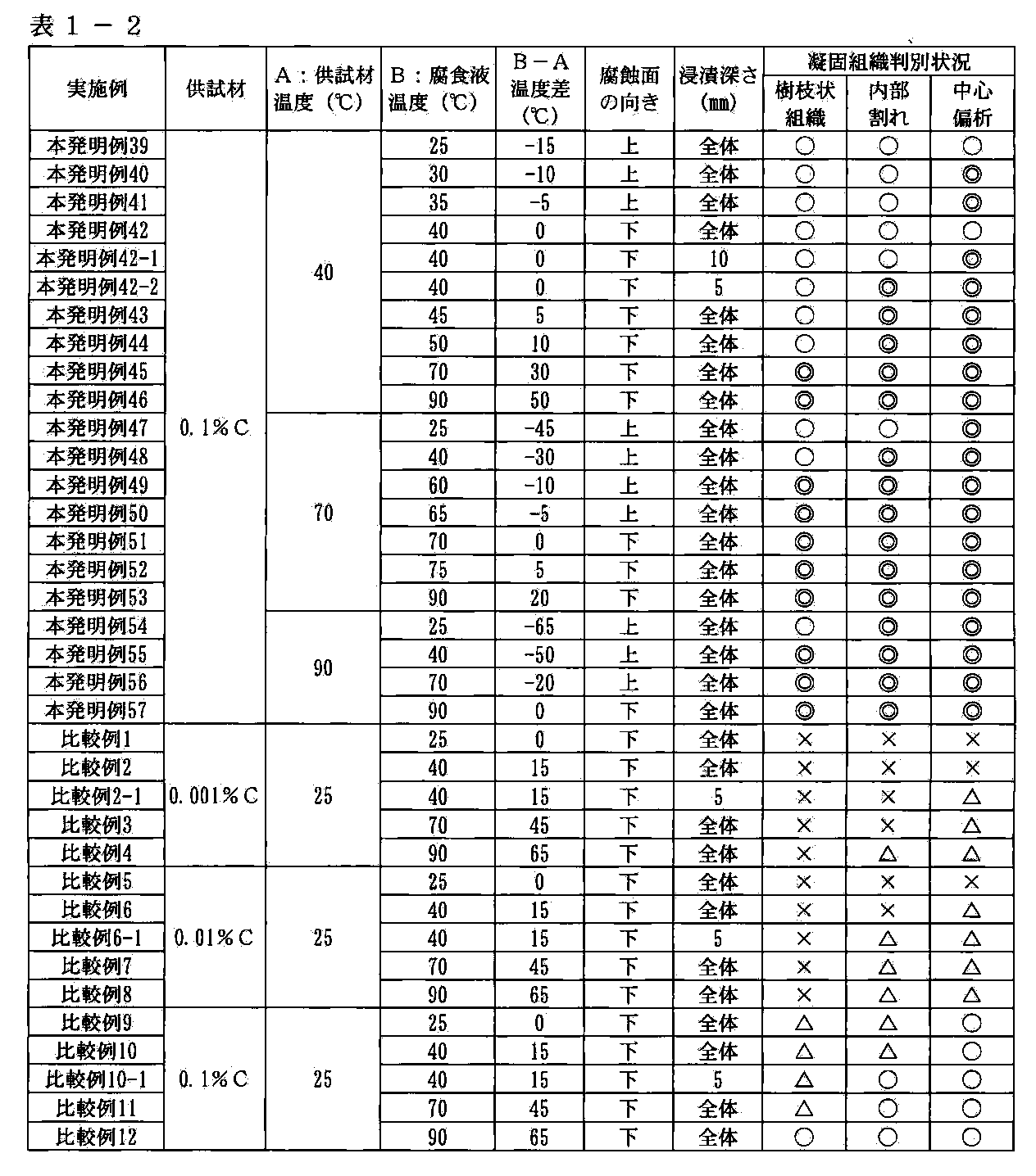
- the level in which "whole" is written in the "immersion depth” column of Table 1 indicates that the entire sample is immersed in the corrosive liquid, and the numerical value is entered in the "immersion depth” column.
- a level is a case where only a part including a polished surface of a sample is immersed, and a numerical value shows the immersion depth in that case.
- Comparative Examples 1 to 12 are the results of the corrosion by the corrosive liquid having the above composition of 25 ° C., 40 ° C., 70 ° C., and 90 ° C. at a sample temperature of 25 ° C.
- a 0.1 mass% C steel which has a relatively large concentration difference due to segregation of solute elements during solidification, it is possible to detect a somewhat clear solidified structure by raising the temperature of the corrosive liquid, as shown in Comparative Example 12
- the temperature of the corrosive solution is 90 ° C., it is possible to distinguish clearly the inclination and interval of the dendritic structure, and the degree of internal cracking and center segregation.
- Inventive Example 4 is the result of corroding a 0.001% C steel with a 40 ° C. corrosion liquid at a sample temperature of 40 ° C.
- Inventive Examples 1, 2 and 3 have 0.001% C It is a result of corroding the steel with a 25, 30 and 35 ° C. etchant respectively at a sample temperature of 40 ° C.
- central segregation can be clearly determined more than invention example 4, and the effect of the thermal convection due to the temperature difference between the sample temperature and the corrosive liquid compensates for the decrease in the corrosive ability due to the lowering of the corrosive liquid temperature. The effect of However, when the temperature difference is 15 ° C.
- the present invention is not limited to the above-described embodiments, and modifications are possible without departing from the scope of the present invention. For example, some or all of the above-described embodiments and modifications may be used. It is also included in the scope of the present invention when combining the above to construct the method for detecting solidified structure of steel of the present invention.
Landscapes
- Chemical & Material Sciences (AREA)
- Engineering & Computer Science (AREA)
- Health & Medical Sciences (AREA)
- Life Sciences & Earth Sciences (AREA)
- Mechanical Engineering (AREA)
- Crystallography & Structural Chemistry (AREA)
- Organic Chemistry (AREA)
- Physics & Mathematics (AREA)
- Metallurgy (AREA)
- Materials Engineering (AREA)
- Medicinal Chemistry (AREA)
- General Chemical & Material Sciences (AREA)
- Immunology (AREA)
- Pathology (AREA)
- General Physics & Mathematics (AREA)
- General Health & Medical Sciences (AREA)
- Biochemistry (AREA)
- Analytical Chemistry (AREA)
- Food Science & Technology (AREA)
- Chemical Kinetics & Catalysis (AREA)
- Thermal Sciences (AREA)
- Sampling And Sample Adjustment (AREA)
- Investigating And Analyzing Materials By Characteristic Methods (AREA)
- ing And Chemical Polishing (AREA)
Abstract
Description
(1)鋼鋳片の試料の断面を研磨し、試料を40~90℃に加熱し、その後試料の研磨面を腐食液に接触させて研磨面を腐食することを特徴とする鋼の凝固組織検出方法。
(2)腐食液を40~90℃に加熱し、その後試料の研磨面を腐食液に接触させることを特徴とする上記(1)に記載の鋼の凝固組織検出方法。
(3)試料の研磨面を腐食液に接触させる際において、腐食液の温度を試料の温度に対して−10~−5℃とすることを特徴とする上記(1)又は(2)に記載の鋼の凝固組織検出方法。
(4)試料の研磨面を上向きにして腐食液に浸漬することを特徴とする上記(3)に記載の鋼の凝固組織検出方法。
(5)試料の研磨面を腐食液に接触させる際において、腐食液の温度を試料の温度に対して+5℃以上とすることを特徴とする上記(2)に記載の鋼の凝固組織検出方法。
(6)試料の研磨面を下向きにして腐食液に浸漬することを特徴とする上記(5)に記載の鋼の凝固組織検出方法。
(7)試料の研磨面を含む一部分のみを腐食液に浸漬することを特徴とする上記(6)に記載の鋼の凝固組織検出方法。
(8)試料の研磨面を腐食液に接触させて研磨面を腐食した後、試料を洗浄、乾燥し、腐食した研磨面表面の腐食孔に研磨粉を埋め込み、研磨面表面に透明粘着テープを貼り、透明粘着テープに腐食孔中の研磨粉を粘着せしめた後、テープをはがし、次いでテープを台紙上に貼りつけることを特徴とする上記(1)乃至(7)のいずれかに記載の鋼の凝固組織検出方法。
(9)鋼鋳片の炭素含有量が0.01質量%以下であることを特徴とする上記(1)乃至(8)のいずれかに記載の鋼の凝固組織検出方法。

Claims (9)
- 鋼鋳片の試料の断面を研磨し、試料を40~90℃に加熱し、その後試料の研磨面を腐食液に接触させて研磨面を腐食することを特徴とする鋼の凝固組織検出方法。
- 腐食液を40~90℃に加熱し、その後試料の研磨面を腐食液に接触させることを特徴とする請求項1に記載の鋼の凝固組織検出方法。
- 試料の研磨面を腐食液に接触させる際において、腐食液の温度を試料の温度に対して−10~−5℃とすることを特徴とする請求項1又は2に記載の鋼の凝固組織検出方法。
- 試料の研磨面を上向きにして腐食液に浸漬することを特徴とする請求項3に記載の鋼の凝固組織検出方法。
- 試料の研磨面を腐食液に接触させる際において、腐食液の温度を試料の温度に対して+5℃以上とすることを特徴とする請求項2に記載の鋼の凝固組織検出方法。
- 試料の研磨面を下向きにして腐食液に浸漬することを特徴とする請求項5に記載の鋼の凝固組織検出方法。
- 試料の研磨面を含む一部分のみを腐食液に浸漬することを特徴とする請求項6に記載の鋼の凝固組織検出方法。
- 試料の研磨面を腐食液に接触させて研磨面を腐食した後、試料を洗浄、乾燥し、腐食した研磨面表面の腐食孔に研磨粉を埋め込み、研磨面表面に透明粘着テープを貼り、透明粘着テープに腐食孔中の研磨粉を粘着せしめた後、テープをはがし、次いでテープを台紙上に貼りつけることを特徴とする請求項1乃至7のいずれかに記載の鋼の凝固組織検出方法。
- 鋼鋳片の炭素含有量が0.01質量%以下であることを特徴とする請求項1乃至8のいずれかに記載の鋼の凝固組織検出方法。
Priority Applications (2)
| Application Number | Priority Date | Filing Date | Title |
|---|---|---|---|
| CN200980147455.3A CN102227633B (zh) | 2008-11-27 | 2009-11-27 | 钢的凝固组织检测方法 |
| BRPI0921171-3A BRPI0921171B1 (pt) | 2008-11-27 | 2009-11-27 | Metodo de detecção de microestrutura de solidificação de aço |
Applications Claiming Priority (2)
| Application Number | Priority Date | Filing Date | Title |
|---|---|---|---|
| JP2008302566A JP5634673B2 (ja) | 2008-11-27 | 2008-11-27 | 鋼の凝固組織検出方法 |
| JP2008-302566 | 2008-11-27 |
Publications (1)
| Publication Number | Publication Date |
|---|---|
| WO2010061968A1 true WO2010061968A1 (ja) | 2010-06-03 |
Family
ID=42225829
Family Applications (1)
| Application Number | Title | Priority Date | Filing Date |
|---|---|---|---|
| PCT/JP2009/070354 Ceased WO2010061968A1 (ja) | 2008-11-27 | 2009-11-27 | 鋼の凝固組織検出方法 |
Country Status (4)
| Country | Link |
|---|---|
| JP (1) | JP5634673B2 (ja) |
| CN (1) | CN102227633B (ja) |
| BR (1) | BRPI0921171B1 (ja) |
| WO (1) | WO2010061968A1 (ja) |
Cited By (2)
| Publication number | Priority date | Publication date | Assignee | Title |
|---|---|---|---|---|
| CN109406238A (zh) * | 2018-12-07 | 2019-03-01 | 郑州机械研究所有限公司 | 一种用于金相试样制备的多功能卡具及金相试样制备方法 |
| CN114018920A (zh) * | 2021-10-29 | 2022-02-08 | 河南中原特钢装备制造有限公司 | 一种显示P91、P92钢中δ铁素体的方法 |
Families Citing this family (1)
| Publication number | Priority date | Publication date | Assignee | Title |
|---|---|---|---|---|
| CN104197858B (zh) * | 2014-09-10 | 2017-05-03 | 重庆大学 | 一种定量描述品种钢连铸坯凝固组织形貌特征的方法 |
Citations (3)
| Publication number | Priority date | Publication date | Assignee | Title |
|---|---|---|---|---|
| JPH06509176A (ja) * | 1991-08-14 | 1994-10-13 | ステルコ インコーポレイテッド | 内部品質を発現させるために金属を電解エッチングするための方法および装置 |
| JPH0943230A (ja) * | 1995-07-31 | 1997-02-14 | Kawasaki Steel Corp | 鉄鋼の旧オーステナイト粒界現出用腐食液およびそれを用いた現出方法 |
| JP2006198649A (ja) * | 2005-01-19 | 2006-08-03 | Kobe Steel Ltd | Hcr可否判定方法 |
Family Cites Families (5)
| Publication number | Priority date | Publication date | Assignee | Title |
|---|---|---|---|---|
| KR960000597B1 (ko) * | 1993-08-09 | 1996-01-09 | 포항종합제철주식회사 | 극저탄소강의 조직관찰을 위한 에칭용액 및 이 용액을 이용한 에칭방법 |
| JP2005164340A (ja) * | 2003-12-01 | 2005-06-23 | Sanyo Special Steel Co Ltd | マルテンサイト系ステンレス鋼又は合金工具鋼の金属組織顕出用の腐食液による腐食方法 |
| JP4604737B2 (ja) * | 2004-01-30 | 2011-01-05 | Jfeスチール株式会社 | 鉄鋼材料の旧オーステナイト粒界現出用腐食液および鉄鋼材料の旧オーステナイト粒界現出方法 |
| CN101144762B (zh) * | 2006-09-13 | 2010-05-12 | 鞍钢股份有限公司 | 一种显示硅钢凝固组织的腐蚀剂及其配制方法 |
| CN100554926C (zh) * | 2007-03-13 | 2009-10-28 | 北京科技大学 | 一种制备超低碳钢金相样品及显示组织的方法 |
-
2008
- 2008-11-27 JP JP2008302566A patent/JP5634673B2/ja active Active
-
2009
- 2009-11-27 BR BRPI0921171-3A patent/BRPI0921171B1/pt active IP Right Grant
- 2009-11-27 WO PCT/JP2009/070354 patent/WO2010061968A1/ja not_active Ceased
- 2009-11-27 CN CN200980147455.3A patent/CN102227633B/zh active Active
Patent Citations (3)
| Publication number | Priority date | Publication date | Assignee | Title |
|---|---|---|---|---|
| JPH06509176A (ja) * | 1991-08-14 | 1994-10-13 | ステルコ インコーポレイテッド | 内部品質を発現させるために金属を電解エッチングするための方法および装置 |
| JPH0943230A (ja) * | 1995-07-31 | 1997-02-14 | Kawasaki Steel Corp | 鉄鋼の旧オーステナイト粒界現出用腐食液およびそれを用いた現出方法 |
| JP2006198649A (ja) * | 2005-01-19 | 2006-08-03 | Kobe Steel Ltd | Hcr可否判定方法 |
Non-Patent Citations (1)
| Title |
|---|
| SHIN'YA KITAMURA ET AL.: "Tei S-ko Oyobi Ca Tenkako no Chushin Henseki Kensaho (Henseki Etch Print-ho) no Kaihatsu", TETSU TO HAGANE, vol. 68, no. 4, 5 March 1982 (1982-03-05), pages S217 * |
Cited By (3)
| Publication number | Priority date | Publication date | Assignee | Title |
|---|---|---|---|---|
| CN109406238A (zh) * | 2018-12-07 | 2019-03-01 | 郑州机械研究所有限公司 | 一种用于金相试样制备的多功能卡具及金相试样制备方法 |
| CN109406238B (zh) * | 2018-12-07 | 2023-10-17 | 郑州机械研究所有限公司 | 一种用于金相试样制备的多功能卡具及金相试样制备方法 |
| CN114018920A (zh) * | 2021-10-29 | 2022-02-08 | 河南中原特钢装备制造有限公司 | 一种显示P91、P92钢中δ铁素体的方法 |
Also Published As
| Publication number | Publication date |
|---|---|
| BRPI0921171A2 (pt) | 2016-02-23 |
| JP2010125483A (ja) | 2010-06-10 |
| CN102227633B (zh) | 2014-06-25 |
| CN102227633A (zh) | 2011-10-26 |
| JP5634673B2 (ja) | 2014-12-03 |
| BRPI0921171B1 (pt) | 2019-04-24 |
Similar Documents
| Publication | Publication Date | Title |
|---|---|---|
| Janik‐Czachor | An assessment of the processes leading to pit nucleation on iron | |
| JP5033112B2 (ja) | 鋼の凝固組織検出方法 | |
| JP4604737B2 (ja) | 鉄鋼材料の旧オーステナイト粒界現出用腐食液および鉄鋼材料の旧オーステナイト粒界現出方法 | |
| CN105200429B (zh) | 一种显示中高牌号无取向硅钢凝固枝晶组织的侵蚀剂及侵蚀方法 | |
| CN105486567A (zh) | 显示膨胀合金宏观低倍组织的化学侵蚀剂及其侵蚀方法 | |
| WO2010061968A1 (ja) | 鋼の凝固組織検出方法 | |
| LIANG et al. | Effect of aging on the mechanical properties and corrosion susceptibility of an Al-Cu-Li-Zr alloy containing Sc | |
| CN103776834A (zh) | 一种低碳er50-6铸坯枝晶的热腐蚀和显示方法 | |
| JP2001289839A (ja) | 炭素鋼あるいは低合金鋼鋳片のデンドライト顕出用腐食液 | |
| CN101995350B (zh) | 一种显示连铸坯半宏观偏析的腐蚀剂及其使用方法 | |
| Hu et al. | The effect of surface treatment on the corrosion behavior of a pure Ta sheet in an equimolar NaCl–KCl melt at 850° C in air. Part 1: Laser surface melting | |
| JP5448432B2 (ja) | 鋼の凝固組織検出方法 | |
| Vasshaug et al. | Formation and dissolution of aluminium carbide in cathode blocks | |
| US4696906A (en) | Test medium solution for detecting phosphorus segregates in metallic material | |
| CN101767192A (zh) | 浇铸制品的制造方法和系统 | |
| CN102313663A (zh) | 一种x70管线钢铸坯枝晶的腐蚀剂及显示方法 | |
| KR102264345B1 (ko) | 알루미늄 판재의 표면 품질 개선 조성물 및 이를 이용한 개선 방법 | |
| JP5790448B2 (ja) | 鋼部材の冷却方法 | |
| KR101187979B1 (ko) | 탕면댐을 구비한 쌍롤식 박판주조기 | |
| JP2008255411A (ja) | アルミニウム合金厚板の製造方法およびアルミニウム合金厚板 | |
| JP2010215934A (ja) | 銅合金材の酸化スケールの除去方法 | |
| JP2002181807A (ja) | フェライト系ステンレス鋼の窒化層検出溶液および検出方法 | |
| KR20110059453A (ko) | 연속주조 슬라브의 중심편석 평가방법 | |
| JPH07120457A (ja) | 極低炭素鋼の凝固組織の検出方法 | |
| JP4210382B2 (ja) | 薄銅箔用エッチング液および薄銅箔エッチング方法 |
Legal Events
| Date | Code | Title | Description |
|---|---|---|---|
| WWE | Wipo information: entry into national phase |
Ref document number: 200980147455.3 Country of ref document: CN |
|
| 121 | Ep: the epo has been informed by wipo that ep was designated in this application |
Ref document number: 09829205 Country of ref document: EP Kind code of ref document: A1 |
|
| WWE | Wipo information: entry into national phase |
Ref document number: 3290/DELNP/2011 Country of ref document: IN |
|
| NENP | Non-entry into the national phase |
Ref country code: DE |
|
| 122 | Ep: pct application non-entry in european phase |
Ref document number: 09829205 Country of ref document: EP Kind code of ref document: A1 |
|
| ENP | Entry into the national phase |
Ref document number: PI0921171 Country of ref document: BR Kind code of ref document: A2 Effective date: 20110527 |