WO2010061791A1 - 映像制御装置およびそれを備えた撮像装置、表示装置 - Google Patents
映像制御装置およびそれを備えた撮像装置、表示装置 Download PDFInfo
- Publication number
- WO2010061791A1 WO2010061791A1 PCT/JP2009/069707 JP2009069707W WO2010061791A1 WO 2010061791 A1 WO2010061791 A1 WO 2010061791A1 JP 2009069707 W JP2009069707 W JP 2009069707W WO 2010061791 A1 WO2010061791 A1 WO 2010061791A1
- Authority
- WO
- WIPO (PCT)
- Prior art keywords
- sound
- motion vector
- image
- unit
- subject
- Prior art date
- Legal status (The legal status is an assumption and is not a legal conclusion. Google has not performed a legal analysis and makes no representation as to the accuracy of the status listed.)
- Ceased
Links
Images


Classifications
-
- H—ELECTRICITY
- H04—ELECTRIC COMMUNICATION TECHNIQUE
- H04N—PICTORIAL COMMUNICATION, e.g. TELEVISION
- H04N5/00—Details of television systems
- H04N5/14—Picture signal circuitry for video frequency region
- H04N5/144—Movement detection
- H04N5/145—Movement estimation
-
- H—ELECTRICITY
- H04—ELECTRIC COMMUNICATION TECHNIQUE
- H04N—PICTORIAL COMMUNICATION, e.g. TELEVISION
- H04N21/00—Selective content distribution, e.g. interactive television or video on demand [VOD]
- H04N21/40—Client devices specifically adapted for the reception of or interaction with content, e.g. set-top-box [STB]; Operations thereof
- H04N21/41—Structure of client; Structure of client peripherals
- H04N21/422—Input-only peripherals, i.e. input devices connected to specially adapted client devices, e.g. global positioning system [GPS]
- H04N21/4223—Cameras
-
- H—ELECTRICITY
- H04—ELECTRIC COMMUNICATION TECHNIQUE
- H04N—PICTORIAL COMMUNICATION, e.g. TELEVISION
- H04N21/00—Selective content distribution, e.g. interactive television or video on demand [VOD]
- H04N21/40—Client devices specifically adapted for the reception of or interaction with content, e.g. set-top-box [STB]; Operations thereof
- H04N21/43—Processing of content or additional data, e.g. demultiplexing additional data from a digital video stream; Elementary client operations, e.g. monitoring of home network or synchronising decoder's clock; Client middleware
- H04N21/439—Processing of audio elementary streams
-
- H—ELECTRICITY
- H04—ELECTRIC COMMUNICATION TECHNIQUE
- H04N—PICTORIAL COMMUNICATION, e.g. TELEVISION
- H04N21/00—Selective content distribution, e.g. interactive television or video on demand [VOD]
- H04N21/40—Client devices specifically adapted for the reception of or interaction with content, e.g. set-top-box [STB]; Operations thereof
- H04N21/43—Processing of content or additional data, e.g. demultiplexing additional data from a digital video stream; Elementary client operations, e.g. monitoring of home network or synchronising decoder's clock; Client middleware
- H04N21/44—Processing of video elementary streams, e.g. splicing a video clip retrieved from local storage with an incoming video stream or rendering scenes according to encoded video stream scene graphs
- H04N21/44008—Processing of video elementary streams, e.g. splicing a video clip retrieved from local storage with an incoming video stream or rendering scenes according to encoded video stream scene graphs involving operations for analysing video streams, e.g. detecting features or characteristics in the video stream
-
- H—ELECTRICITY
- H04—ELECTRIC COMMUNICATION TECHNIQUE
- H04N—PICTORIAL COMMUNICATION, e.g. TELEVISION
- H04N5/00—Details of television systems
- H04N5/76—Television signal recording
- H04N5/765—Interface circuits between an apparatus for recording and another apparatus
- H04N5/77—Interface circuits between an apparatus for recording and another apparatus between a recording apparatus and a television camera
- H04N5/772—Interface circuits between an apparatus for recording and another apparatus between a recording apparatus and a television camera the recording apparatus and the television camera being placed in the same enclosure
-
- H—ELECTRICITY
- H04—ELECTRIC COMMUNICATION TECHNIQUE
- H04S—STEREOPHONIC SYSTEMS
- H04S7/00—Indicating arrangements; Control arrangements, e.g. balance control
- H04S7/30—Control circuits for electronic adaptation of the sound field
-
- H—ELECTRICITY
- H04—ELECTRIC COMMUNICATION TECHNIQUE
- H04S—STEREOPHONIC SYSTEMS
- H04S1/00—Two-channel systems
- H04S1/007—Two-channel systems in which the audio signals are in digital form
-
- H—ELECTRICITY
- H04—ELECTRIC COMMUNICATION TECHNIQUE
- H04S—STEREOPHONIC SYSTEMS
- H04S2400/00—Details of stereophonic systems covered by H04S but not provided for in its groups
- H04S2400/11—Positioning of individual sound objects, e.g. moving airplane, within a sound field
-
- H—ELECTRICITY
- H04—ELECTRIC COMMUNICATION TECHNIQUE
- H04S—STEREOPHONIC SYSTEMS
- H04S2400/00—Details of stereophonic systems covered by H04S but not provided for in its groups
- H04S2400/13—Aspects of volume control, not necessarily automatic, in stereophonic sound systems
Definitions
- the present invention relates to a control technology for an imaging device and a display device, and more particularly to a method for controlling an image and sound.
- the digital camera has as its main components an image pickup unit that picks up an image, a sound pickup unit that picks up sound, and a storage unit that records images and sound.
- an image pickup unit that picks up an image
- a sound pickup unit that picks up sound
- a storage unit that records images and sound.
- the video with a sense of presence referred to here is a video with a sense that a viewer who sees the captured video is actually on the spot. For example, even if you watch a picture of a waterfall in the living room, you can tell it without damaging the sparkle of water splashing when you see the waterfall directly, or the force of the sound of water falling into the waterfall. It is.
- Patent Document 1 proposes a volume control device that controls the volume level and the left / right volume balance according to the zoom magnification of the camera and the angle of the camera with respect to the subject. For example, when a subject that is talking in a video conference system or the like is photographed with a large zoom, control is performed such that an image with a volume increased in accordance with the zoom magnification is acquired.
- JP-A-9-168139 JP-A-9-168139
- the object of the present invention is to acquire a video with a higher presence.
- a video control apparatus is associated with a subject, a motion vector detection unit that detects a motion vector from the motion of the subject in the video signal, a sound image processing unit that associates the motion vector with a sound emitted from the subject, and a subject
- a sound control unit that controls sound based on a motion vector.
- the video control apparatus is characterized in that the position of a subject is specified based on position information in a display area or position information of divided blocks.
- the video control apparatus is characterized in that the position and volume of the subject are calculated based on a volume balance of at least two or more sound collecting units.
- the video control apparatus is characterized in that the sound control unit changes at least one of a loudness and a sound frequency linearly or nonlinearly based on a motion vector.
- the video control apparatus includes a setting unit that changes the degree of non-linearity or the linear inclination by a user setting.
- An imaging apparatus includes a camera lens that collects light, an imaging element that captures an image collected by the camera lens, a sound collection unit that collects sound from a subject, and a memory that records a video signal.
- a motion vector detection unit that detects a motion of a subject as a motion vector from an image captured by an image sensor, and sound image processing that associates the sound collected by the sound collection unit with the motion vector
- a sound control unit that controls a sound associated with the subject based on a motion vector, and the sound and the image controlled by the sound control unit are recorded in a storage unit.
- An imaging apparatus includes a camera lens that collects light, an imaging element that captures an image collected by the camera lens, a sound collection unit that collects sound from a subject, and a memory that records a video signal.
- a motion vector detecting unit that detects a motion of a subject as a motion vector from an image captured by the image sensor, and a sound image processing unit that associates the sound collected by the sound collecting unit with the motion vector
- a sound control unit that controls the associated sound based on the motion vector, the motion vector and sound association information associated by the sound image processing unit, the sound collected by the sound collection unit, And an image are recorded in a storage unit.
- the imaging apparatus is characterized in that in the sound control unit, the control of the sound controlled according to the motion vector is the volume of the sound collected by the sound collection unit.
- the image pickup apparatus is characterized in that in the sound control unit, the control of the sound controlled according to the motion vector is the frequency of the sound collected by the sound collection unit.
- An imaging apparatus includes a sensor that detects a movement direction and a movement amount of the imaging apparatus, and detects a motion vector of the imaging apparatus detected from the movement direction and the movement amount from a motion vector detected from the image.
- the motion vector of the subject is detected by removing the motion vector.
- a display device is a display device that includes an image signal display unit that displays an input image and a sound signal playback unit that plays back an input sound, and moves a subject from the video signal.
- a motion vector detection unit that detects a vector; a sound image processing unit that associates a sound emitted from a subject with a motion vector; and a sound control unit that controls a sound associated with the motion vector; The sound displayed on the signal display unit and controlled by the sound control unit is reproduced by the sound signal reproduction unit.
- a display device is a display device including an image signal display unit that displays an input image and a sound signal reproduction unit that reproduces an input sound, and the input video signal is image information.
- a sound control unit that controls sound that is associated with the motion vector, and includes sound information, image motion vector information, and sound information associated with the motion vector. The sound that is displayed on the image signal display unit and controlled by the sound control unit is reproduced by the sound signal reproduction unit.
- the video control apparatus of the present invention it is possible to acquire a video with enhanced realism by associating the movement of the subject with the sound.
- the imaging apparatus including the video control apparatus of the present invention, it is possible to capture a realistic video by associating the movement of the subject with the sound and controlling the sound according to the movement of the subject.
- a realistic video can be displayed by controlling the sound according to the movement of the subject.
- subject in this specification refers to an object that is mainly desired to be photographed in a video or the like, and is distinguished from the background. For example, humans, animals, vehicles, and the like are applicable.
- FIG. 1A is a functional block diagram showing a configuration example of a digital video camera according to the first embodiment of the present invention.
- the digital video camera according to the first embodiment includes a video control device 107 (dotted line portion) in the preceding stage of the storage unit 103.
- the video control device 107 includes a motion vector detection unit 102, a sound image processing unit 105, and a sound control unit 106.
- the video signal includes an image signal and a sound signal.
- the operation of each functional unit in FIG. 1A will be described below.
- An image collected by the camera lens 100 is captured by the image sensor 101.
- the image pickup device 101 includes a CCD (Charged Coupled Device) image sensor, a CMOS (Complementary MetalMetaOxide Semiconductor) image sensor, and the like.
- the image sensor 101 is driven by a sensor controller (not shown).
- An image signal 108 received by the image sensor 101 is input to the motion vector detection unit 102 of the video control device 107.
- the motion vector detection unit 102 detects a motion vector of the input image signal 108 and outputs a motion vector signal 110 to the sound image processing unit 105.
- the motion vector is a vector representing the moving direction and moving amount of the subject on the screen per unit time.
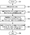
- a block matching method can be used to detect the motion vector. In the block matching method, inter-frame matching is performed in an appropriately determined block unit, and the most similar block between frames is determined as a corresponding block, and a motion vector is detected. The motion vector detection procedure by the block matching method will be described below based on the flowchart of FIG. 1B.
- step S1 the process is started (step S1). Assume that an image captured at time t is f 1 , and an image captured at time t + ⁇ is f 2 .
- the pixel value at the coordinates (x, y) in the image is represented by f (x, y).
- Processing procedure 1 The image f 1 is divided into N ⁇ M (N and M are arbitrary natural numbers, step S2).
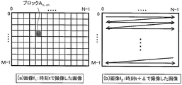
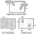
- FIG. 2 is a diagram illustrating a state of motion vector search.
- FIG. 2A shows an image f 2 captured at time t + ⁇ to detect the motion vector of the block An and m in the image f 1 captured at time t and the motion vector of the block An and m in FIG. It is a figure which shows the mode of search of.
- FIG. 2B the entire search is performed by the raster scan method, but the processing amount can be reduced by limiting the search range in the vicinity of the blocks An and m .
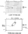
- FIG. 3 is a diagram illustrating an example of a motion vector search result.
- Image f 1 captured at time t in FIG. 3 (a) shows a diagram illustrating a motion vector detected with the image f 2 captured at time t + delta in FIG. 3 (b).
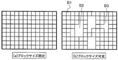
- the block size variable does not divide any image into a square lattice. For example, if there are humans and a background tree, the human is 1 block and the background tree is 1 block. This means that a block is assigned to what is shown in the image.
- the advantage of fixing the block size is that the processing is simple because it is only divided into square lattices, and there is a problem that the movement of the object is not taken into consideration.
- the advantage of making the block size variable is that it is possible to detect the rough movement of the object, and the problem is that the process needs to be divided according to the object in the image, so the processing is complicated It is to become.
- the block matching method is used for motion vector detection, but the same effect can be obtained even when the gradient method is used.
- the gradient method is a known technique for detecting a motion vector by calculating a constraint equation derived based on the assumption that a change in luminance in an image is caused only by the motion of an object.
- the sound collection unit 104 collects sound emitted from the subject.
- the sound collection unit 104 includes a stereo microphone and a microphone that can control directivity, and inputs the collected sound to the sound image processing unit 105 of the video control device 107.
- the sound image processing unit 105 associates the motion vector with the sound and outputs the sound 111 to the sound control unit 106.
- a method for associating the motion vector 110 with the sound 111 will be described below. Since the position of the moving subject is known from the motion vector detected by the motion vector detection unit 102, the sound collected at the position where the subject exists can be extracted and associated with the motion vector.
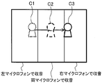
- the volume in the block can be calculated based on the balance between the left and right volume.
- the number of microphones for collecting sound is increased, the sound volume from a specific block or region can be obtained with high accuracy, particularly when four places are arranged in a plane.
- the volume in the left and right direction can be known, so that it is possible to grasp the simple volume at a certain position or region.
- the following method is applicable.
- Association method 1 This is a method in which a motion vector is detected for each divided block and a sound is associated with each block.
- Association method 2 An image is divided into regions based on color information and texture information, a motion vector is detected for each divided region, and a sound is associated with each region.
- Association method 3 Detecting a motion vector for each divided block, segmenting an image based on color information and texture information, and superimposing the motion vector detection result and the region segmentation result, This is a method of associating sounds with each region.
- the association method 1 is a method for associating motion vectors and sounds in units of blocks
- the association method 2 and the association method 3 are methods for associating motion vectors and sounds in units of regions.
- the associating method 1 is FIG. 4A fixed block size
- the associating methods 2 and 3 are FIG. 4B variable block size.
- FIG. 6 is a diagram showing a specific example of the association method. As shown in FIG. 6A, the captured moving image and the arrow indicate the motion vector, and the case of recording this will be described below.
- FIG. 6B is a diagram showing an example in which motion vectors and sounds are associated with each other in units of blocks. Block A and sound signal A are associated with each other, and block B and sound signal B are associated with each other.
- FIG. 6C shows an example of associating a motion vector with a sound in units of regions, in which region A and sound signal A are associated with each other, and region B and sound signal B are associated with each other.
- the correspondence information 112 between the sound signal and the motion vector processed by the sound image processing unit 105 is input to the sound control unit 106.
- the sound controller 106 controls the sound using the direction and magnitude of the motion vector.
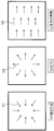
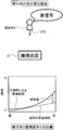
- the direction of the motion vector in the present embodiment, three types of (a) moving away direction, (b) approaching direction, and (c) horizontal movement shown in FIG. 7 will be described.
- the motion vector of the subject is in the direction of approaching (FIG. 7B)
- the associated sound is increased to give a sense of realism.
- a sense of reality is obtained by making the sound smaller.
- the sense of reality is enhanced by adjusting the left and right volume so that sound can be heard from the subject position.
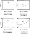
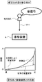
- FIGS. 8A and 8B show the difference between conventional sound control and sound control according to the present invention.
- the conventional sound control shown in FIG. 8A does not depend on the magnitude of the motion vector.
- the magnitude of the control amount of the sound is changed nonlinearly according to the magnitude of the motion vector to increase the force. Since a subject with a large motion vector has a high moving speed, the control amount of the sound is further increased to produce a flashy sound.
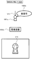
- FIG. 9 a case will be described in which a subject approaches while speaking out from the back of the drawing.
- the sound control amount is increased.
- FIG. 9B when the subject approaches the imaging device, the sound control amount is reduced.
- the sense of reality can be enhanced by changing the amount of sound control between when the subject walks and when the subject approaches and emphasizes the difference in motion of the subject (in this case, speed).
- the control amount is shown as an example of a positive value, but it may be a negative value.
- the control amount is set to a negative value, and the volume is reduced to increase the sense of reality.
- the sound control amount may be set to 0.
- FIG. 8 (c) and 8 (d) are diagrams showing the difference between the conventional sound frequency control and the sound frequency control according to this embodiment.
- the frequency is changed nonlinearly according to the magnitude of the motion vector, and it is associated with a subject having a large motion vector (fast moving speed).
- the sound corresponding to the movement of the subject is controlled by controlling the sound associated with the subject having a small motion vector (slow moving speed) to be a lower frequency.
- the frequency may be controlled according to the direction of the motion vector. For example, in the case of an image in which a car runs from left to right, the frequency of the engine sound associated with the car is changed. When the car approaches the imaging device from the left, increase the frequency. Conversely, when the car moves away from the imaging device to the right, it is possible to enhance the sense of reality by lowering the frequency.
- the loudness and the frequency of the sound are changed nonlinearly, but the sense of presence may be enhanced by changing linearly according to the degree of presence and the degree of desire to obtain force.
- the degree of nonlinearity may be adjusted.
- the degree of nonlinearity and the linear inclination may be changed by user settings. Further, even if only one of the volume and frequency of the sound is controlled, a sound signal with enhanced realism can be obtained.
- the storage unit 103 can record a video signal with enhanced realism by recording the image signal 109 and the sound signal 113.
- the example in which the image signal and the sound signal are recorded in the storage unit 103 has been described.
- the motion vector and the sound association information may be recorded.
- the difference between the information to be recorded (image signal and sound signal, motion vector and sound association information) will be described.
- the reproduction side Only sounds with amplified presence can be output.
- the motion vector and the sound association information are stored at the same time, it is possible to know where the object is present on the screen and how much the object has moved. Therefore, on the playback side, it is possible to make a sound from the position where the object is moving on the screen, or to amplify the sound to increase the sense of reality.
- the video control apparatus detects a motion vector from a video signal, associates the detected motion vector with a sound signal, and controls the sound based on the motion vector, thereby providing a sense of presence. It is possible to create a video signal with an improved image quality. Further, by providing the video control device in the imaging device, the captured video and the collected sound can be recorded in association with each other, and an imaging device capable of capturing a video with enhanced realism. Can be obtained.
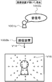
- FIG. 10 is a diagram illustrating motion vectors detected when the subject moves and when the imaging device moves.
- FIG. 10A is a diagram showing a motion vector when the imaging device 1002a is fixed and the subject 1001a moves.
- the motion vector appears on the moving subject 1001a and does not appear on the background without motion. Since the position of the moving subject 1001a is known from the motion vector appearance range, the sound signal 1000a emitted from the moving subject 1001a is collected and associated with the motion vector.
- FIG. 10B is a diagram illustrating a motion vector when the imaging device 1002b is moving and the subject 1001b is stationary.
- the motion vector appears in both the subject 1001b without motion and the background.
- a motion vector having substantially the same size appears in one of the three types of patterns shown in FIG. 7 in the entire image, it is estimated that the imaging device 1002b is moving.
- the sound signal 1000b is associated with the center of the screen.
- FIG. 7C it is estimated from the sound signal 1000b whether the sounding body is on the left or right, and the motion vector existing at the estimated position is associated with the sound signal.
- the sound signal picked up by the left microphone is compared with the sound signal picked up by the left microphone and the sound signal picked up by the right microphone. If the volume of is high, it is estimated that the subject is on the left side of the imaging apparatus.
- FIG. 11 is a diagram illustrating a motion vector when the imaging apparatus 1102 and the subject 1101 are moving together.
- the motion vector appears in both the moving subject 1101 and the background.
- the direction and magnitude of the motion vector appearing in the background may be different from those of the subject 1101 in motion, and the direction or magnitude of the motion vector may be different. is there.
- the subject 1101 is extracted from the difference between the direction and the magnitude of the motion vector.
- the extracted subject 1101 is associated with the sound signal.
- the motion of the imaging device is estimated from the motion vector, but an acceleration sensor or a gyro sensor can be used to estimate the motion of the imaging device.
- the motion vector of the imaging device is detected by an acceleration sensor or a gyro sensor, and is output to the motion vector detection unit 102.
- the motion vector detection unit 102 detects the motion vector of the subject by removing the motion vector of the imaging apparatus from the motion vector detected by the motion vector detection unit 102. Since the detected motion vector is a motion vector of a subject that is not affected by the motion of the imaging device, the same sound correlation method as in FIG. 10A can be used even if the imaging device is moving.
- a subject that is actually moving can be extracted by detecting the movement of the imaging apparatus with a sensor and combining the sensor detection value with the motion vector.
- a realistic video signal can be obtained.
- the motion vector is detected from the video signal, the detected motion vector and the sound signal are associated, and the motion vector is detected. It is possible to create a video signal with enhanced realism by controlling the sound by.
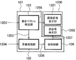
- FIG. 12 is a functional block diagram illustrating a configuration example of the display device according to the present embodiment. However, portions having the same functions as those in the first embodiment are denoted by the same reference numerals.
- a display device 1200 shown in FIG. 12 includes a video control device 107, an image signal display unit 1201, and a sound signal reproduction unit 1202.
- An input video signal includes an image signal and a sound signal.
- the image signal 1203 is input to the motion vector detection unit 102, and the sound signal 1204 is input to the sound image processing unit 105.
- the motion vector detection unit 102 detects the motion vector of the subject from the image signal 1203 using the method described in the first embodiment.
- the detected motion vector information 1205 is output to the sound image processing unit 105.
- the sound image processing unit 105 receives the sound signal 1204 and the motion vector information 1205, and associates the sound with the motion vector using the method described in the first embodiment.
- the sound image processing unit 105 outputs the sound signal, the motion vector, and the sound association information 1206 to the sound control unit 106.
- the sound control unit 106 controls the sound signal by using the method described in the first embodiment, and enhances the presence of the video.
- the sound control unit 106 outputs a sound signal 1207 with enhanced realism to the sound signal reproduction unit 1202.
- the image signal 1208 is output from the motion vector detection unit 102 to the image signal display unit 1201.
- the image signal 1208 is displayed on the image signal display unit 1201, and the sound signal 1207 is reproduced on the sound signal reproduction unit 1202, thereby reproducing an image with enhanced realism.
- the motion vector is detected from the image signal, the detected motion vector and the sound signal are associated, By controlling the sound with the vector, it is possible to display a video signal with enhanced realism.
- Example 4 a fourth embodiment of the present invention will be described in detail with reference to the drawings.
- the sound for collecting the sound collected by the imaging device, the motion vector detected by the video control device, and the sound association information are recorded in the storage unit, and the volume for enhancing the sense of presence using the motion vector on the display device Control is performed.
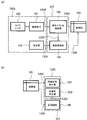
- 13 and 14 are functional block diagrams showing an example of the configuration of this embodiment. However, parts having the same functions as those in the first and third embodiments are denoted by the same reference numerals and description thereof is omitted.
- a video signal captured by an imaging device such as a web camera is stored in a storage unit such as a hard disk, and can be displayed on a display device such as a television or a monitor by reading the video signal from the storage unit. It is a thing.
- a video signal captured by an imaging device such as a digital camera is stored in a storage unit such as an optical disk or a memory card, and the video signal is read from the storage unit so that it can be displayed on a display device.
- the imaging device 1308 includes a camera lens 100, an imaging element 101, and a sound collection unit 104.
- An image signal 1300 obtained from the camera lens 100 and the image sensor 101 is output to the motion vector detection unit 102.
- the sound signal 1304 collected by the sound collection unit 104 is output to the sound image processing unit 105.
- the motion vector detection unit 103 detects a motion vector from the image signal 1300 using the method described in the first embodiment.
- the detected motion vector information 1303 is output to the sound image processing unit 105.
- the sound image processing unit 105 associates the motion vector information 1303 and the sound signal 1304 using the method described in the first embodiment.
- the image signal 1301 is input from the motion vector detection unit 102, and the sound signal, the motion vector, and the sound association information 1305 are input from the sound image processing unit 105 to the storage unit 103.
- the image information 1302 is output from the storage unit 103 to the image signal display unit 1201. Further, the sound signal, the motion vector, and the sound association information 1306 are output from the storage unit 103 to the sound control unit 106.
- the sound control unit 106 performs volume control using the method described in the first embodiment. From the sound control unit 106, the sound signal 1307 with enhanced realism is output to the sound signal reproduction unit 1202. In the display device 1200, the image signal 1302 is displayed on the image signal display unit 1201 and the sound signal 1307 is reproduced on the sound signal reproduction unit 1202.
- the storage unit 103 records sound signals, motion vectors, and sound association information. By doing so, it is possible to freely adjust the presence of the video on the display side.
- the motion vector is detected from the video signal obtained by the imaging device, and the detected motion vector and sound are detected.
- the signals By associating the signals with each other and controlling the sound using the motion vector, it is possible to display a video signal with enhanced realism.
- the video, the motion vector, and the sound association information recorded by the imaging device are recorded by the storage device. It is possible to change the realistic sensation of the video image with the display device.
- a program for realizing the functions described in the present embodiment is recorded on a computer-readable recording medium, and the program recorded on the recording medium is read into a computer system and executed to execute processing of each unit. May be performed.
- the “computer system” here includes an OS and hardware such as peripheral devices.
- the “computer system” includes a homepage providing environment (or display environment) if a WWW system is used.
- the “computer-readable recording medium” means a storage device such as a flexible disk, a magneto-optical disk, a portable medium such as a ROM and a CD-ROM, and a hard disk incorporated in a computer system. Furthermore, the “computer-readable recording medium” dynamically holds a program for a short time like a communication line when transmitting a program via a network such as the Internet or a communication line such as a telephone line. In this case, a volatile memory in a computer system serving as a server or a client in that case is also used to hold a program for a certain period of time.
- the program may be a program for realizing a part of the above-described functions, or may be a program that can realize the above-described functions in combination with a program already recorded in a computer system. .
- the present invention can be used for a digital video camera or the like.
Landscapes
- Engineering & Computer Science (AREA)
- Signal Processing (AREA)
- Multimedia (AREA)
- Physics & Mathematics (AREA)
- Acoustics & Sound (AREA)
- Studio Devices (AREA)
Applications Claiming Priority (2)
| Application Number | Priority Date | Filing Date | Title |
|---|---|---|---|
| JP2008-303494 | 2008-11-28 | ||
| JP2008303494A JP2010130403A (ja) | 2008-11-28 | 2008-11-28 | 映像制御装置およびそれを備えた撮像装置、表示装置 |
Publications (1)
| Publication Number | Publication Date |
|---|---|
| WO2010061791A1 true WO2010061791A1 (ja) | 2010-06-03 |
Family
ID=42225667
Family Applications (1)
| Application Number | Title | Priority Date | Filing Date |
|---|---|---|---|
| PCT/JP2009/069707 Ceased WO2010061791A1 (ja) | 2008-11-28 | 2009-11-20 | 映像制御装置およびそれを備えた撮像装置、表示装置 |
Country Status (2)
| Country | Link |
|---|---|
| JP (1) | JP2010130403A (enExample) |
| WO (1) | WO2010061791A1 (enExample) |
Families Citing this family (3)
| Publication number | Priority date | Publication date | Assignee | Title |
|---|---|---|---|---|
| JP2010200084A (ja) * | 2009-02-26 | 2010-09-09 | Nikon Corp | 撮像装置 |
| CN105451139A (zh) * | 2014-06-24 | 2016-03-30 | 索尼公司 | 声音信号处理方法、装置和移动终端 |
| KR20210091003A (ko) | 2020-01-13 | 2021-07-21 | 삼성전자주식회사 | 전자 장치 및 그 제어 방법 |
Citations (11)
| Publication number | Priority date | Publication date | Assignee | Title |
|---|---|---|---|---|
| JPH01296900A (ja) * | 1988-05-25 | 1989-11-30 | Nippon Telegr & Teleph Corp <Ntt> | 音像定位制御方式 |
| JPH0515587U (ja) * | 1991-07-31 | 1993-02-26 | ミノルタカメラ株式会社 | ビデオ装置 |
| JPH08181962A (ja) * | 1994-12-22 | 1996-07-12 | Hitachi Ltd | 音像定位方法および音像定位制御装置およびテレビ会議システム |
| JPH09219858A (ja) * | 1996-02-13 | 1997-08-19 | Matsushita Electric Ind Co Ltd | 映像音声符号化装置及び映像音声復号化装置 |
| JP2000004493A (ja) * | 1998-06-17 | 2000-01-07 | Matsushita Electric Ind Co Ltd | ビデオカメラ |
| JP2001169309A (ja) * | 1999-12-13 | 2001-06-22 | Mega Chips Corp | 情報記録装置および情報再生装置 |
| JP2003264900A (ja) * | 2002-03-07 | 2003-09-19 | Sony Corp | 音響提示システムと音響取得装置と音響再生装置及びその方法並びにコンピュータ読み取り可能な記録媒体と音響提示プログラム |
| JP2004147205A (ja) * | 2002-10-25 | 2004-05-20 | Fuji Photo Film Co Ltd | 画像音声記録装置 |
| JP2004187288A (ja) * | 2002-11-20 | 2004-07-02 | Haruhiko Onozato | 音源映像の表示領域からその音声を出力させる映像音声再生方法 |
| JP2005311604A (ja) * | 2004-04-20 | 2005-11-04 | Sony Corp | 情報処理装置及び情報処理装置に用いるプログラム |
| JP2006128818A (ja) * | 2004-10-26 | 2006-05-18 | Victor Co Of Japan Ltd | 立体映像・立体音響対応記録プログラム、再生プログラム、記録装置、再生装置及び記録メディア |
Family Cites Families (4)
| Publication number | Priority date | Publication date | Assignee | Title |
|---|---|---|---|---|
| JP2756293B2 (ja) * | 1989-02-06 | 1998-05-25 | キヤノン株式会社 | 自動焦点調節装置 |
| JPH06315200A (ja) * | 1993-04-28 | 1994-11-08 | Victor Co Of Japan Ltd | 音像定位処理における距離感制御方法 |
| JP3997501B2 (ja) * | 1998-09-03 | 2007-10-24 | ソニー株式会社 | 被写体認識装置、被写体認識方法、自動追尾装置及び自動追尾方法 |
| JP2003079000A (ja) * | 2001-09-05 | 2003-03-14 | Junichi Kakumoto | 映像音響装置の臨場感制御方式 |
-
2008
- 2008-11-28 JP JP2008303494A patent/JP2010130403A/ja active Pending
-
2009
- 2009-11-20 WO PCT/JP2009/069707 patent/WO2010061791A1/ja not_active Ceased
Patent Citations (11)
| Publication number | Priority date | Publication date | Assignee | Title |
|---|---|---|---|---|
| JPH01296900A (ja) * | 1988-05-25 | 1989-11-30 | Nippon Telegr & Teleph Corp <Ntt> | 音像定位制御方式 |
| JPH0515587U (ja) * | 1991-07-31 | 1993-02-26 | ミノルタカメラ株式会社 | ビデオ装置 |
| JPH08181962A (ja) * | 1994-12-22 | 1996-07-12 | Hitachi Ltd | 音像定位方法および音像定位制御装置およびテレビ会議システム |
| JPH09219858A (ja) * | 1996-02-13 | 1997-08-19 | Matsushita Electric Ind Co Ltd | 映像音声符号化装置及び映像音声復号化装置 |
| JP2000004493A (ja) * | 1998-06-17 | 2000-01-07 | Matsushita Electric Ind Co Ltd | ビデオカメラ |
| JP2001169309A (ja) * | 1999-12-13 | 2001-06-22 | Mega Chips Corp | 情報記録装置および情報再生装置 |
| JP2003264900A (ja) * | 2002-03-07 | 2003-09-19 | Sony Corp | 音響提示システムと音響取得装置と音響再生装置及びその方法並びにコンピュータ読み取り可能な記録媒体と音響提示プログラム |
| JP2004147205A (ja) * | 2002-10-25 | 2004-05-20 | Fuji Photo Film Co Ltd | 画像音声記録装置 |
| JP2004187288A (ja) * | 2002-11-20 | 2004-07-02 | Haruhiko Onozato | 音源映像の表示領域からその音声を出力させる映像音声再生方法 |
| JP2005311604A (ja) * | 2004-04-20 | 2005-11-04 | Sony Corp | 情報処理装置及び情報処理装置に用いるプログラム |
| JP2006128818A (ja) * | 2004-10-26 | 2006-05-18 | Victor Co Of Japan Ltd | 立体映像・立体音響対応記録プログラム、再生プログラム、記録装置、再生装置及び記録メディア |
Also Published As
| Publication number | Publication date |
|---|---|
| JP2010130403A (ja) | 2010-06-10 |
Similar Documents
| Publication | Publication Date | Title |
|---|---|---|
| CN101729781B (zh) | 显示控制设备和显示控制方法 | |
| US9940969B2 (en) | Audio/video methods and systems | |
| JP5428210B2 (ja) | 情報処理装置、撮像システム、録画制御方法及びプログラム | |
| JP4934580B2 (ja) | 映像音声記録装置および映像音声再生装置 | |
| CN112165590A (zh) | 视频的录制实现方法、装置及电子设备 | |
| JP6012342B2 (ja) | 再生装置、再生装置の制御方法 | |
| WO2011099299A1 (ja) | 映像抽出装置、撮影装置、プログラム及び記録媒体 | |
| JP5155092B2 (ja) | カメラ、再生装置、および再生方法 | |
| JP2012178807A (ja) | 撮像装置 | |
| JP2009065587A (ja) | 音声記録装置及び音声再生装置 | |
| WO2010061791A1 (ja) | 映像制御装置およびそれを備えた撮像装置、表示装置 | |
| JP2003264900A (ja) | 音響提示システムと音響取得装置と音響再生装置及びその方法並びにコンピュータ読み取り可能な記録媒体と音響提示プログラム | |
| JP2011041154A (ja) | 画像処理装置、画像処理方法 | |
| JP5712599B2 (ja) | 撮像装置及びプログラム | |
| CN114175616B (zh) | 图像处理设备、图像处理方法和程序 | |
| JP2004147205A (ja) | 画像音声記録装置 | |
| JP2013141090A (ja) | 撮影装置及びその処理方法 | |
| JP4515005B2 (ja) | 電子カメラ | |
| JP2001008285A (ja) | 音声帯域信号処理方法及び音声帯域信号処理装置 | |
| JP2021002803A (ja) | 画像処理装置、その制御方法、プログラム | |
| JP2015080167A (ja) | 撮像装置、その制御方法、および制御プログラム | |
| JP2010183254A (ja) | 撮像装置および被写体検出プログラム | |
| JP5659856B2 (ja) | 撮像装置、撮像方法、及びプログラム | |
| JP2012216936A (ja) | 撮像装置及びプログラム | |
| JP2016024764A (ja) | 撮像装置、その制御方法およびプログラム |
Legal Events
| Date | Code | Title | Description |
|---|---|---|---|
| 121 | Ep: the epo has been informed by wipo that ep was designated in this application |
Ref document number: 09829039 Country of ref document: EP Kind code of ref document: A1 |
|
| NENP | Non-entry into the national phase |
Ref country code: DE |
|
| 122 | Ep: pct application non-entry in european phase |
Ref document number: 09829039 Country of ref document: EP Kind code of ref document: A1 |